US5608850A - Transporting a display object coupled to a viewpoint within or between navigable workspaces - Google Patents
Transporting a display object coupled to a viewpoint within or between navigable workspaces Download PDFInfo
- Publication number
- US5608850A US5608850A US08/227,762 US22776294A US5608850A US 5608850 A US5608850 A US 5608850A US 22776294 A US22776294 A US 22776294A US 5608850 A US5608850 A US 5608850A
- Authority
- US
- United States
- Prior art keywords
- viewpoint
- display object
- workspace
- data
- selected display
- Prior art date
- Legal status (The legal status is an assumption and is not a legal conclusion. Google has not performed a legal analysis and makes no representation as to the accuracy of the status listed.)
- Expired - Lifetime
Links
- 238000000034 method Methods 0.000 claims abstract description 91
- 238000010168 coupling process Methods 0.000 claims abstract description 41
- 230000008878 coupling Effects 0.000 claims abstract description 40
- 238000005859 coupling reaction Methods 0.000 claims abstract description 40
- 230000004044 response Effects 0.000 claims description 57
- 230000002452 interceptive effect Effects 0.000 claims description 22
- 230000009471 action Effects 0.000 claims description 17
- 238000006073 displacement reaction Methods 0.000 claims description 16
- 238000003860 storage Methods 0.000 claims description 12
- 238000013500 data storage Methods 0.000 claims description 11
- 230000003993 interaction Effects 0.000 claims description 4
- 238000004519 manufacturing process Methods 0.000 claims description 3
- 230000006872 improvement Effects 0.000 claims 3
- 238000012800 visualization Methods 0.000 abstract description 7
- 230000008859 change Effects 0.000 description 23
- 230000008447 perception Effects 0.000 description 21
- 238000009877 rendering Methods 0.000 description 15
- 238000012545 processing Methods 0.000 description 13
- 238000012360 testing method Methods 0.000 description 12
- 230000006870 function Effects 0.000 description 10
- 230000000007 visual effect Effects 0.000 description 9
- 230000007246 mechanism Effects 0.000 description 7
- 238000013519 translation Methods 0.000 description 6
- 230000008569 process Effects 0.000 description 5
- XUIMIQQOPSSXEZ-UHFFFAOYSA-N Silicon Chemical compound [Si] XUIMIQQOPSSXEZ-UHFFFAOYSA-N 0.000 description 4
- 238000004891 communication Methods 0.000 description 4
- 230000004048 modification Effects 0.000 description 4
- 238000012986 modification Methods 0.000 description 4
- 229910052710 silicon Inorganic materials 0.000 description 4
- 239000010703 silicon Substances 0.000 description 4
- 230000007704 transition Effects 0.000 description 3
- 230000008901 benefit Effects 0.000 description 2
- 230000003287 optical effect Effects 0.000 description 2
- 238000002360 preparation method Methods 0.000 description 2
- 239000004065 semiconductor Substances 0.000 description 2
- 238000012546 transfer Methods 0.000 description 2
- 241001422033 Thestylus Species 0.000 description 1
- 238000013459 approach Methods 0.000 description 1
- 230000006399 behavior Effects 0.000 description 1
- 230000001427 coherent effect Effects 0.000 description 1
- 238000004590 computer program Methods 0.000 description 1
- 230000000881 depressing effect Effects 0.000 description 1
- 238000010586 diagram Methods 0.000 description 1
- 230000008571 general function Effects 0.000 description 1
- 239000011521 glass Substances 0.000 description 1
- 230000004886 head movement Effects 0.000 description 1
- 230000000977 initiatory effect Effects 0.000 description 1
- 238000013507 mapping Methods 0.000 description 1
- 239000000463 material Substances 0.000 description 1
- 230000003340 mental effect Effects 0.000 description 1
- 230000008520 organization Effects 0.000 description 1
- 238000003825 pressing Methods 0.000 description 1
- 238000007493 shaping process Methods 0.000 description 1
- 238000004088 simulation Methods 0.000 description 1
- 239000000126 substance Substances 0.000 description 1
Images


Classifications
-
- G—PHYSICS
- G06—COMPUTING; CALCULATING OR COUNTING
- G06F—ELECTRIC DIGITAL DATA PROCESSING
- G06F3/00—Input arrangements for transferring data to be processed into a form capable of being handled by the computer; Output arrangements for transferring data from processing unit to output unit, e.g. interface arrangements
- G06F3/01—Input arrangements or combined input and output arrangements for interaction between user and computer
- G06F3/048—Interaction techniques based on graphical user interfaces [GUI]
- G06F3/0481—Interaction techniques based on graphical user interfaces [GUI] based on specific properties of the displayed interaction object or a metaphor-based environment, e.g. interaction with desktop elements like windows or icons, or assisted by a cursor's changing behaviour or appearance
- G06F3/04815—Interaction with a metaphor-based environment or interaction object displayed as three-dimensional, e.g. changing the user viewpoint with respect to the environment or object
-
- G—PHYSICS
- G06—COMPUTING; CALCULATING OR COUNTING
- G06F—ELECTRIC DIGITAL DATA PROCESSING
- G06F3/00—Input arrangements for transferring data to be processed into a form capable of being handled by the computer; Output arrangements for transferring data from processing unit to output unit, e.g. interface arrangements
- G06F3/01—Input arrangements or combined input and output arrangements for interaction between user and computer
- G06F3/048—Interaction techniques based on graphical user interfaces [GUI]
- G06F3/0484—Interaction techniques based on graphical user interfaces [GUI] for the control of specific functions or operations, e.g. selecting or manipulating an object, an image or a displayed text element, setting a parameter value or selecting a range
- G06F3/04845—Interaction techniques based on graphical user interfaces [GUI] for the control of specific functions or operations, e.g. selecting or manipulating an object, an image or a displayed text element, setting a parameter value or selecting a range for image manipulation, e.g. dragging, rotation, expansion or change of colour
Definitions
- the present invention relates to an interactive user interface method of transporting a display object within a single or from one to another, n-dimensional workspace of a processor-controlled system, wherein the display object remains coupled to a first viewpoint while being transported.
- GUIs display based, graphical user interfaces
- 2D two-dimensional desktop metaphor where information is presented in a single large 2D display region bounded by the physical size of the display area of the display device that serves as the metaphorical desktop and that may include other 2D display regions, called windows, the opening, closing, and manipulation of which are controlled by the system user.
- the system user interacts with--that is, performs operations on--displayed 2D graphical objects, such as icons, menus, and dialog boxes, using a pointing device.
- the graphical desktop may be considered to be the system user's workspace, and is constrained by the physical size of the particular display area, or screen, being used. All of the information associated with a particular window may not be able to be displayed in the window at one time, and is typically accessible via a scrolling mechanism.
- a common interaction technique provided by the single workspace, 2D desktop GUI is that of moving or copying display objects to another position in the workspace, or from one window to another.
- Common techniques for selecting, moving and copying (collectively referred to herein as "transporting") data, information or objects in a conventional 2D GUI are well-known.
- One technique uses a "drag-and-drop" metaphor in which the system user selects a display object such as an icon using the pointing device by depressing a button on the device.
- the system attaches the icon to the cursor under the control of the pointing device as long as the user continues to depress the button; the user then uses the pointing device to drag the cursor across the display, simulating motion of the selected object to a new position perceptible in the display area, positioning the object in its destination position by releasing the button on the pointing device.
- This technique is provided, and works effectively, when the entire 2D workspace, including the display object being transported and the destination position, are always perceptible and there is, therefore, only one fixed viewpoint from which the 2D workspace is viewed by the system user.
- This technique is typically not provided for transporting objects within a window in the workspace to a destination position that is not perceptible at the time that the display object is selected for transporting.
- Another common technique used for selecting and transporting data, information or objects in a conventional 2D GUI is called "cut-and-paste" and employs a memory location, typically called a “clipboard”, to store the data being transported while the system user finds the destination position in the 2D workspace.
- This technique is provided, and works effectively, when the destination position in the 2D workspace is not perceptible to the system user. For example, in a window that contains display objects representing the text of a document, only the portion of the document that fits in the window region is perceptible at any one time. There is typically provided a scrolling mechanism for bringing a new portion of the document into view in place of the currently displayed portion.
- the user in order to move a text display object from one portion of the document to another, the user typically selects the text display object with the pointing device, executes a "cut" command, and the data representing the selected text display object is stored on the clipboard (i.e., in the clipboard memory location) and the display object may be removed from the window and may no longer be perceptible to the user.
- the user then scrolls to bring a new portion of the document into view that includes the intended destination of the data in the document, selects the destination position, and executes a "paste" command.
- the user could designate a destination position in a second window.
- the data representing the selected text display object is then retrieved from the memory location and presented in the destination position.
- the display object being transported is not perceptible to the user because it is removed from the window at the time it is cut, and during a copy operation, the display object being transported is not perceptible to the user if the scrolling process removes the display object from view.
- a variation of the cut-and-paste technique highlights the selected display object to be transported, and places the cursor in a special operation "mode" that allows the user to perform no other operations on display objects until the current operation has been completed.
- the user is permitted operations with the cursor that change the view of the information displayed, such as scrolling in a window, in order to find the destination position.
- the display object being operated on is not perceptible to the user if the scrolling process removes it from view, and it moves in the window as the document is being scrolled so as to remain in a position relative to its neighboring display objects.
- Some GUIs attempt to provide the user with the perception that his or her immediate workspace is larger than is actually displayed in the display area.
- the 2D desktop metaphor of the single workspace has been extended to multiple 2D desktop workspaces in a GUI called "Rooms" that permits a user to switch among workspaces, allowing more information to reside in the immediate work area.
- Rooms® is a registered trademark of Xerox Corporation. Henderson, D. A. and Card, S. K., "Rooms: The use of multiple virtual workspaces to reduce space contention in a window-based graphical user interface", ACM Transactions on Graphics, July, 1986, pp.
- Rooms® permits the sharing of information objects in different workspaces, provides the ability to store and retrieve workspaces, and provides an overview of available workspaces and other navigational aids to assist the system user in locating objects and working in the various workspaces.
- Each 2D workspace Room except in the Overview, occupies most, if not all, of the available display area and has a single, fixed viewpoint.
- the first mechanism uses an Overview, shown in FIG.
- a "placement" which is a window together with location and presentation information in a particular Room, can be copied or moved from one Room to another Room, or within a single Room, via a COPY or MOVE command.
- a second mechanism utilizes a "baggage" metaphor that permits the user to carry,--that is, copy--tools (typically windows) with him or her as the user transits to another workspace.
- ARK “Alternate Reality Kit” supporting the navigable shared workspace disclosed in U.S. Pat. No. 5,107,443. ARK is also described in Smith, R., "The Alternate Reality Kit: An Animated Environment for Creating Interactive Simulations," 1986 IEEE Computer Society Workshop on Visual Languages, Jun. 25-27, 1986, Dallas, Tex., pp. 99-106. ARK supports a class of system object known as a "teleporter” which a user can use to make a transition from one location in navigable workspace to a location somewhere else in the navigable workspace using paired teleporters. The user does so using the conventional drag-and-drop technique to drop an object onto the teleporter in the origin location.
- the system positions the object in the part of the shared workspace near the paired teleporter in the destination location, and at the same time makes a transition so that the view shows the part of the shared workspace that includes the paired teleporter and the object in its new location.
- a teleported object thus disappears from the first view during transporting and reappears in the second view.
- the ARK user interface may be considered to display a 21/2D workspace, since the user-controlled cursor, in the shape of a hand, appears as though it floats in a plane above the other display objects.
- Pad is an infinite 2D information plane that is shared among users and populated by Pad Objects with which a user can interact. Pad Objects are organized geographically; every object occupies a well defined region on the Pad surface.
- Pad objects make themselves visible through two mechanisms: a graphic and a portal, which is a view into the single, infinite shared desktop, analogous to a magnification glass that can peer into and roam over different parts of the Pad surface, and thus portals are used for navigation in the workspace using a navigation technique called semantic zooming.
- a navigation technique called semantic zooming.
- Robertson, Card and Mackinlay in "Interactive Visualization Using 3D Interactive Animation", Communications ACM, 36, 4, April 1993, pp. 57-71 disclose a 3D navigable workspace containing graphical objects representing visualizations of information, known as the Information Visualizer.
- the Robertson article discloses that the Information Visualizer evolved the multiple desktop user interface of Rooms® into a 3D workspace for information access in which 3D Interactive Objects replace the windows of the 2D Rooms environment.
- System users can have arbitrary positions and orientations in each Room, and techniques are provided for rapid, controlled and targeted 3D movement by the user in the workspace, such as the technique disclosed in U.S. Pat. No.
- the movement technique based on 2D mouse input, integrates point-of-interest viewpoint movement, uses the mouse cursor to control a ray that determines the lateral position of the object, and uses keyboard keys to control the position of the object on the ray.
- the Mackinlay article further discloses that objects moved in this way are constrained to remain in the 3D room by clipping the object's new coordinates to the room coordinates.
- the drag-and-drop technique couples the display object to the cursor and is typically restricted to transporting a selected display object only when the viewpoint into the workspace is fixed and the destination position is perceptible, requiring its use in a context where the entire workspace is displayable on the display device, such as in the Overview of the Rooms® GUI;
- the conventional cut-and-paste technique does not attach a selected display object to the cursor, but removes it from the user's view while it is being operated on, and multiple objects transported at the same time do not remain in the same relationship relative to each other. Movement via teleporters in the ARK system appear to require additional steps to position the teleporters in the workspace.
- the point-of-interest object movement technique disclosed in the Mackinlay article is not suitable for moving objects between workspaces.
- the present invention recognizes that different problems arise with respect to tracking and manipulating objects in a multiple viewpoint, navigable workspace from those that arise in a conventional, single viewpoint environment.
- the techniques described above for transporting a display object in a workspace often result in the selected display object disappearing from the user's view while being transported, are not applicable to transporting display objects between workspaces, or do not use standard interface navigation techniques for transporting display objects. As a result, these techniques potentially increase user disorientation while navigating in the workspace, and could affect information access efficiency.
- the technique of the present invention solves these problems in a multiple viewpoint, single or multiple navigable workspace environment by coupling the position of a selected display object to the user's viewpoint into the workspace at the time the object is selected for transporting, and then permitting the use of standard navigation techniques for transporting the display object to its destination location.
- the selected display object remains perceptible to the system user during transporting as it was perceptible at the time it was selected, and the system user will always be able to track the object being transported and have more precise control over its final positioning.
- the technique prevents the selected display object from disappearing from the user's view when the user selects another viewpoint into the same workspace, or into another workspace, that would not otherwise include a view of the selected display object.
- several display objects selected for transporting will remain in the same fixed relationship to each other as well as to the user as they were when they were first selected, and they will appear to the user in that fixed relationship when the user selects a second viewpoint from which to view the workspace.
- the present invention for transporting a display object may be used in any navigable, multiple viewpoint 2D, 21/2D, or 3D workspace, or between any two types of such workspaces.
- An additional user interface feature provides for displaying the selected display object with a display feature that visually distinguishes, or highlights, the display object to the system user as being selected for transporting.
- the transporting technique applies to both move and copy operations on the selected display object within a single workspace, or between workspaces.
- the data structure representing the selected display object is modified appropriately for a move or copy operation on the selected display object in a single workspace
- the workspace data structures are modified appropriately for a move or copy operation between workspaces.
- This technique can be implemented on a processor-controlled system that includes a user input device for producing signals indicating actions of a system user; a display; a processor connected for receiving signals and for presenting images on the display; and memory for storing data.
- a first image is presented on the display that is perceptible as viewed from a first viewpoint in a first navigable workspace.
- the first image includes a first display object, and the first viewpoint is positioned at a first coordinate position and orientation relative to the first display object.
- a first signal is received from the system user indicating the system user's request to transport the first display object, the first signal also indicating the system user's selection of the first display object as a selected display object.
- the selected display object is coupled to the first viewpoint.
- a second signal is then received, indicating a selection by the system user of a second viewpoint.
- a second image is presented on the display that is perceptible as viewed from the second viewpoint.
- the second image includes the selected display object presented using the first viewpoint and orientation so that the selected display object is perceptible as being viewed from the first viewpoint position and orientation.
- the present invention is premised on the discovery that a display object selected for transporting can be made to remain in a first perceptible relationship to the user when the viewpoint into the navigable workspace changes by actually adjusting the position in the workspace (and also the orientation or scale, depending on the number of dimensions in the workspace) of the selected display object as successive viewpoint changes are requested.
- coupling a selected display object to the first viewpoint is accomplished in one embodiment by storing first viewpoint coordinate and viewpoint orientation data for the first viewpoint when a second viewpoint into the workspace is selected.
- the selected display object is presented in a second image as perceptible as viewed from the first viewpoint by changing the selected display object's position and orientation data in the workspace by the difference between the saved viewpoint coordinate data and the second viewpoint coordinate data, and by the difference between the saved first viewpoint orientation data and the second viewpoint orientation data.
- An end-of-transport signal is then received from the user input device indicating that transporting of the selected display object has been completed.
- the selected display object is decoupled from the first viewpoint, and a third image is presented in the display area.
- the third image includes the selected display object perceptible as viewed from the second viewpoint. Decoupling a display object is accomplished when the display object's position and orientation data is no longer changed using stored viewpoint coordinate data, when there is a change in the viewpoint.
- Another aspect of the transporting technique of the present invention integrates the transporting technique with the user interface's navigation, or viewpoint motion, technique. Integrating the transporting technique with the navigation techniques provided by the user interface recognizes that an effective transporting technique should be consistent with the overall metaphor of the multiple viewpoint GUI and results in increasing the effectiveness of the metaphor and the usefulness of the user interface.
- a plurality of viewpoint selection signals are received.
- a respective image is presented that is perceptible to the system user as viewed from the next viewpoint.
- the selected display object is presented in the respective image using the stored viewpoint coordinate data so that the selected display object is perceptible as being viewed from the first viewpoint.
- the present invention implemented as a processor-controlled system may include input circuitry, connected to a user input device, for receiving signals indicating actions of a system user; output circuitry connected to a display device having a display area for presenting images; a processor connected for receiving the signals from the input circuitry, and connected for providing images to the output circuitry for presentation by the display device; and instruction data stored in memory indicating instructions the processor can access and execute.
- the processor presents a first image on the display that is perceptible as viewed from a first viewpoint in a first n-dimensional workspace and that includes a first display object.
- the processor then carries out the transporting technique as described above.
- the invention can also be implemented as an article of manufacture for use in a system that includes a storage medium access device such as a floppy disk drive or a CD drive.
- the article can include a data storage medium such as a floppy disk or a CD-ROM and data stored by the medium.
- the stored data indicates user signal input instructions and processor response instructions which carry out the transporting technique as described above.
- FIG. 1 schematic view of display objects in a first navigable workspace
- FIG. 2 is a schematic view of a presented image that includes the display objects shown in FIG. 1 from a first viewpoint;
- FIG. 3 is a schematic view of a presented image that includes the display objects shown in FIG. 1 from a second viewpoint;
- FIG. 4 is a schematic view of a presented image that includes the display objects shown in FIG. 1 from the first viewpoint, and showing a transport command cursor;
- FIG. 5 is a schematic view of a presented image, presented in response to a system user selecting a display object for transporting according to the steps shown in FIG. 20;
- FIG. 6 is a schematic view of a presented image, presented in response to a system user selecting a second viewpoint from which to view the workspace of FIG. 1 according to the steps shown in FIG. 20;
- FIGS. 7-9 are a sequence of schematic views of presented images that illustrate viewpoint motion in the workspace of FIG. 1, and illustrate coupling a selected display object to a first viewpoint, according to the steps shown in FIG. 20;
- FIG. 10 is a schematic view of a presented image, presented in response to the system receiving an end-of-transport signal according to the steps shown in FIG. 20;
- FIG. 11 is a schematic view of a presented image that illustrates viewpoint motion in the workspace of FIG. 1, and illustrates the decoupling of a selected display object from a first viewpoint, according to the steps shown in FIG. 20;
- FIG. 12 is a schematic view of the transported display object in its new absolute position in the first navigable workspace
- FIG. 13 is a schematic view of display objects in a second navigable workspace
- FIG. 14 is a schematic view of a presented image that includes the display objects shown in the navigable workspace of FIG. 13 from a viewpoint therein;
- FIG. 15 is a schematic view of a presented image that includes the display objects shown in the first workspace of FIG. 1 from a viewpoint therein, showing them selected for transporting;
- FIG. 16 is a schematic view of a presented image that includes the second workspace of FIG. 13 from a viewpoint therein, and shows the selected display objects moved from the first workspace to the second workspace, in a position coupled to the viewpoint of the first workspace;
- FIG. 17 is a schematic view of a presented image that includes the second workspace of FIG. 13 from the first viewpoint, including the moved display objects perceived from the first viewpoint in the second workspace;
- FIG. 18 is a schematic view of a presented image that includes the display objects shown in the first workspace of FIG. 1 from a first viewpoint therein, showing one display object selected for copying;
- FIG. 19 is a schematic view of a presented image that includes the display objects shown in the first workspace of FIG. 1 from a second viewpoint therein, showing both the copied, selected display object and the original display object;
- FIG. 20 is a flow chart illustrating the steps of the present invention for transporting a display object in a workspace
- FIG. 21 is a simplified block diagram illustrating the system environment in which the present invention may be used, the system configuration of the system of the present invention, and the software product of the present invention;
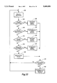
- FIG. 22 is a flow chart illustrating the animation loop as it relates to input events for transporting a display object between workspaces according to an implementation of the present invention
- FIG. 23 is a flow chart illustrating a routine for initiating transport of an object, according to an implementation of the present invention.
- FIG. 24 is a flow chart illustrating a routine for terminating the transport operation and decoupling all selected display objects from the viewpoint, according to an implementation of the present invention
- FIG. 25 is a flow chart illustrating the steps of routine 380 of FIGS. 24 and 26 for decoupling a single display object from the viewpoint according to an implementation of the present invention
- FIG. 26 is a flow chart illustrating a routine for terminating the transport operation for a single selected display object, according to an implementation of the present invention
- FIG. 27 is a flow chart illustrating a routine for presenting a new workspace, according to an implementation of the present invention.
- FIG. 28 is a flow chart illustrating the animation loop rendering routine for drawing the workspace, according to an implementation of the present invention.
- FIGS. 29-34 are a sequence of schematic views of presented images that illustrate viewpoint motion in a 21/2D workspace, and illustrate coupling a selected display object to a first viewpoint, according to the steps shown in FIG. 20, and in FIGS. 22-28; and
- FIGS. 35-37 are a sequence of schematic views of presented images that illustrate viewpoint motion in a scrollable window of a 2D workspace, and illustrate coupling a selected display object to a first viewpoint, according to the steps shown in FIG. 20, and in FIGS. 22-28.
- the present invention is related to an invention described in the copending, commonly assigned patent application by the same inventor, Ser. No. 08/227,763, entitled “Coupling a Display Object To a Viewpoint in a Navigable Workspace", which is hereby incorporated by reference herein.
- the present invention relates to operating a machine or system including a processor, and to processing electrical or other physical signals to produce other desired physical signals.
- the detailed descriptions which follow are presented largely in terms of display images and symbolic representations of operations of data within the memory of the system. These descriptions and representations, which are algorithmic in nature, are the techniques used by those skilled in the data processing arts to most effectively convey the substance of their work to others skilled in the art.
- An algorithm is here, and generally, conceived to be a self consistent sequence of acts leading to a desired result. These acts are those requiring physical manipulations of physical quantities such as electrical or magnetic signals that are capable of being stored, transferred, combined, compared, and otherwise manipulated.
- manipulations performed are often referred to in terms, such as adding, comparing, or determining, which are commonly associated with mental operations performed by a human user.
- the capability of a human user is neither necessary nor desirable in the operations described herein which form part of the present invention.
- data refers herein to physical signals that indicate or include information.
- Data items can be combined into a “data structure” such that the data structure "includes” the combined data items; thus, a “data structure” is any combination of interrelated data.
- a data structure may also include other data structures.
- An item of data "indicates" a thing, an event, or a characteristic when the item has a value that depends on the existence or occurrence of the thing, event, or characteristic or on a measure of the thing, event, or characteristic.
- the item of data has one of a number of "values”.
- viewpoint coordinate data indicates information about the viewpoint into a three dimensional workspace when the viewpoint coordinate data includes a value for the x, y and z coordinates of the position of the viewpoint and a value for the x, y and z coordinates of the orientation of the viewpoint in the workspace.
- a first item of data "indicates" a second item of data when the second item of data can be obtained from the first item of data, when the second item of data can be accessible using the first item of data, when the second item of data can be obtained by decoding the first item of data, or when the first item of data can be an identifier of the second item of data.
- a first item of data indicates position information of an image display feature in the display area of a display device, and the position information may be used by the processor to obtain a second data item in a data structure
- the first item of data indicates the second item of data.
- a "processor-controlled system” or “processor” is any machine, component or system that can process data, and may include one or more central processing units or other processing components. Any two components of a machine or system are “connected” when there is a combination of circuitry that can transfer data from one of the components to the other.
- An "instruction” is an item of data that a processor can use to determine its own operation.
- a processor "uses” data in performing an operation when the result of the operation depends on the value of the data.
- a processor executes a set of instructions when it uses the instructions to determine its operation, and an "operation" results from the processor executing the set of instructions. Thus, a set of instructions may be considered to be an operation.
- Memory is any component, combination of components, circuitry, or system that can store data, and may include local and remote memory and input/output devices.
- An example of memory is a storage medium access device with a data storage medium that it can access.
- a "data storage medium” or “storage medium” is a physical medium that can store data. Examples of data storage media include magnetic media such as floppy disks and PCMCIA memory cards, optical media such as CD-ROMs, and semiconductor media such as semiconductor ROMs and RAMs.
- storage medium covers one or more distinct units of a medium that together store a body of data. For example, a set of floppy disks storing a single body of data would be a storage medium.
- a “storage medium access device” is a device with circuitry that can access data on a data storage medium. Examples include floppy disk drives and CD-ROM readers.
- An “image” is a pattern of light.
- a “display” or “display device” is a device that provides output defining an image that includes information in human perceptible form.
- a display may, for example, include a cathode ray tube; an array of light emitting, reflecting, or absorbing elements; a device or structure that presents marks on paper or another medium; or any other device or structure capable of defining an image in a visible form.
- a “display area” is the portion of the display in which an image is presented or the medium which receives an image. Data “defines” an image when the data includes sufficient information for the processor to directly produce the image, such as by presenting the image on a display. Data defining an image may be referred to as "image definition data”.
- the processor "presents" an image on a display when an operation executed by the processor produces image definition data defining the image and provides the image definition data defining the image to output circuitry connected to the display for display in the display area so that the image is perceptible to a system user.
- display feature refers to any human perception produced by the display in the system.
- a "display object” is a visually distinguishable display feature that is perceptible as a coherent unity.
- a display object “includes” a display feature if presentation of the display object can produce perception of the display feature.
- a display object that has a distinguishable outline and a bounded area may be called a "region”.
- An image “includes” a display feature or display object if presentation of the image can produce perception of the feature or display object.
- display object 22 in FIG. 5 "includes" display features 35 when the system user can perceive the display features presented, such as, for example, the narrow, colored vertical bars or stripes that have been added to selected display object 22 in FIG. 5 indicating that the display object has been selected for transporting.
- a display feature "represents" a body of data when the display feature can be mapped to one or more items of data in the body of data, or, stated in another way, a display feature "represents" the item or items of data to which it can be mapped.
- the display object selected in the first image for transporting may represent one or more object data structures that have values indicating both display information about the display object, such as, for example, its coordinates in the workspace, its graphical or character shape, its color and the like, and content information, such as character data.
- a “workspace” is a display feature within which other display features or display objects in an image are perceived as having respective spatial positions relative to each other, as for example, in a space.
- a workspace can be a display feature with a visible boundary on the display, such as a window, but a workspace need not have a visible outer boundary, nor does the entire workspace need to be displayed at one time in order to produce the perception of a workspace.
- the presentation of a workspace, or a portion thereof produces the human perception of display features in respective relative positions.
- a workspace is perceived as being viewed from a viewing position, and this position is called the "viewpoint."
- the viewpoint may be one of many positions within the workspace.
- the viewpoint is a viewing position into the workspace that is typically orthogonal to the workspace.
- a 2D workspace may have more than one viewpoint into the workspace from which it may be viewed.
- An example of such a 2D workspace is a 2D window that provides for changing the contents displayed in the window, as, for example, by scrolling the window's contents. This scrolling effectively results in changing the viewpoint in the minus-y direction in a 2D plane defined by an x-y coordinate axis.
- a "three-dimensional workspace” is a workspace that is perceived as extending in three orthogonal dimensions.
- a display has a 2D display surface and the perception of a third dimension is produced by visual clues such as perspective lines extending toward a vanishing point; obscuring of distant objects by near objects; size changes in objects moving toward or away from the viewer; perspective shaping of objects; different shading of objects at different distances from the viewer, and so forth.
- Three-dimensional (3D) workspaces include not only workspaces in which all of these cues combine to produce the perception of three dimensions, but also workspaces in which a single cue can produce the perception of three dimensions.
- a workspace with overlapping display objects or a workspace within which a view can zoom in on a display object can be a 3D workspace even though display objects within it are presented in orthographic projection, without perspective.
- This latter example of a workspace is often referred to as a "21/2D" workspace.
- Data indicating the viewpoint into a 3D workspace includes x, y, and z coordinate data indicating the viewpoint's position.
- Data indicating the viewpoint into a 3D workspace may also include data indicating the viewpoint's "direction of orientation" into the workspace.
- the direction of orientation is the direction from the viewpoint into the field of view along the axis at the center of the field of view.
- Each viewpoint into a 3D workspace provides a view into the workspace that is delineated by a truncated pyramid structure called a viewing frustrum.
- An example of a viewing frustrum is shown in FIG. 1.
- a viewing frustrum is specified by specifying two items: the position of the user's eye and the position of a point in the workspace to be centered in the view.
- a viewing transform automatically produces an axis defined by these two items which is called the "line of sight.”
- the "line of sight” is a ray cast from the user's eye through the center of the viewing frustrum and produces an axis orthogonal to the image surface of the display.
- a viewpoint into a workspace may be controlled by a system user using a user input device that provides signals for controlling the viewpoint, such as, for example, one or more key combinations on a keyboard, or the pressing of buttons on a mouse, or by a body-mounted device that senses actual physical movement, such as a head-mounted device that senses head movement.
- a viewpoint into a workspace is distinguishable from a cursor position in the workspace with which a user may directly manipulate objects in the workspace.
- Viewpoint motion occurs when a sequence of images is presented that are perceptible as a series of views of an n-dimensional workspace from each of a series of moving or displaced viewpoints. This perception may result from perception of display features or display objects in the workspace as “continuations” or “moved continuations.”
- a second display feature is perceptible as a "continuation" of a first display feature when presentation of the second display feature follows presentation of the first display feature in such a way that the user perceives the first display feature as being continued when the second display feature is presented. This can occur when the successive display of two display features is so close in time and space that they appear to be the same display feature.
- a second display feature is perceptible as a "moved continuation" of a first display feature if it is perceptible as a continuation in a different position.
- the first display feature is perceived as "moving” or as having “movement” or “motion” or as being “displaced.”
- a "navigable workspace” is a workspace in which a user can determine the part of the workspace that is presented on the display by requesting changes in the viewpoint. Presentation of part of a navigable workspace in response to a user input signal requesting viewpoint motion, can produce the perception of controlling movement within a workspace. Signals from a user input device requesting a change of viewpoint into the workspace are synonymous with a user action requesting viewpoint motion.
- the location of a display object included in a workspace is described by its position in the workspace, which is called its "absolute position.”
- the object's absolute position is expressed by its x, y coordinates in the workspace.
- a display object's absolute position is expressed by its x, y, z coordinate position.
- the location of a display object is also described by its absolute orientation in the workspace.
- display objects 20 and 22 in FIG. 1 each have an orientation in 3D workspace 10 that is expressed by the x, y, z coordinates of the object's rotation, scaling, and translation in the workspace.
- the absolute orientation of display object 514 is expressed by the object's scale in the workspace.
- a display object included in a workspace may also have the characteristic of being "location sensitive,” and "user selectable,” meaning that the entire display object, or a display feature within the display object, may be selected by user signals indicating the location of that display feature, or of the display object, in the workspace.
- an action by a user "indicates" a thing, an event, or a characteristic when the action demonstrates or points out the thing, event or characteristic in a manner that is distinguishable from actions that do not indicate the thing, event, or characteristic.
- a signal from a user input device indicates selection of a location sensitive display object, or indicates a position in an image, if the signal includes data from which the display object or position can be uniquely identified.
- a system can find a point in the display plane based on the previous pointer position. This point can then be used to project a ray from the viewpoint into the 3D workspace being presented, and the coordinates of display objects in the workspace can be used to find the nearest display object intersected by the ray.
- a set of instructions constituting an operation may be represented by a location sensitive, selectable display object in an image.
- a user signal may include a request to initiate or invoke an operation and information identifying the requested operation, wherein the signal or signals indicate one or more actions by a system user intended to cause performance of the operation.
- An operation is performed by the system "in response" to one or more user signals when the signals received are for indicating a valid request for a valid operation and for causing the operation to be performed.
- Signals indicating a single complete request or action may include a combination of any number of signals indicating a valid request for a valid operation and for causing the operation to be performed.
- FIGS. 1-20 illustrate the general features of the present invention of transporting a display object to a destination position within a navigable workspace, or between navigable workspaces.
- FIGS. 1-3 illustrate the general concept of multiple viewpoints into a navigable workspace.
- FIGS. 4-11 illustrate the sequence of presented images resulting from transporting a display object in a navigable workspace according to the present invention, and
- FIG. 12 shows the resulting position of the transported objects.
- FIGS. 13-17 illustrate a sequence of presented images resulting from transporting a display object from a first navigable workspace to a second workspace.
- FIGS. 18 and 19 illustrate the initial sequence of images that result from copying a display object for transporting.
- FIG. 20 illustrates the general steps of the present invention.
- FIG. 1 illustrates navigable workspace 10, which happens to be a three-dimensional workspace, with the orthogonal axes oriented as shown.
- Workspace 10 contains two display objects 20 and 22; display object 22 is location sensitive. Display objects 20 and 22 each have a coordinate position in workspace 10 which is called the object's absolute position.
- FIG. 1 also illustrates first and second viewpoints 14 and 24 into navigable workspace 10.
- the user viewing workspace 10 from viewpoint 14 will see image 40 in FIG. 2; thus, image 40 is perceived by the system user as viewed from viewpoint 14 in workspace 10.
- Coordinate axis 38 shows the orientation of the coordinate axis of workspace 10 from viewpoint 14.
- Each viewpoint into workspace 10 provides a view into the workspace that is delineated by a truncated pyramid structure called a viewing frustrum.
- Viewpoint 24 provides a view into workspace 10 that is illustrated by viewing frustrum 16.
- the user viewing workspace 10 from viewpoint 24 will see image 44 in FIG. 3.
- Coordinate axis 36 shows the orientation of the coordinate axis of workspace 10 from viewpoint 24.
- FIG. 2 illustrates a first image 40 presented according to box 210 in FIG. 20.
- the system user perceives image 40 as viewed from first viewpoint 14; image 40 includes display object 22.
- step 220 receives signals from the system user indicating a transport command.
- FIG. 4 illustrates image 46 into workspace 10 from first viewpoint 14, and also illustrates transport command cursor 36, which is presented in response to the transport command signal; transport command cursor 36 provides a visual indication to the system user that the transport command has been selected, and that a display object in workspace 10 should be selected for transporting.
- the user may select a display object by moving transport cursor 36 to display object 22, for example, along line 38 in workspace 10.
- the system preferably presents selected display object 22 with some sort of visual indication that the object has been selected.
- FIG. 5 illustrates image 48 presenting selected display object 22 having a pair 35 of vertical colored display features to provide this visual feedback.
- Any suitable visual change to the selected display object such as, for example, changing its color, adding a drop shadow, or making its outline display features thicker, may be used in place of the illustrated pair 35 of vertical colored display features, and such a visual change to the display features of the selected display object will hereafter be called "transport highlighting.”
- selected display object 22 is preferably presented in image 48 with no portion of the object obscured by any other display object. This is accomplished by rendering selected display object 22 last in image 48, such that any objects in workspace 10 and image 48 that might otherwise be rendered in a sequence that would obscure all or part of selected display object 22 cannot do so. Also in response to selecting display object 22 for transporting, the step in box 220 couples selected display object 22 to first viewpoint 14 during transporting.
- the step in box 230 receives a second viewpoint signal indicating the user's selection of a second viewpoint.
- the second viewpoint will be viewpoint 24 shown in workspace 10, but the second viewpoint may be a viewpoint selected in a second workspace, as discussed below in the discussion accompanying FIGS. 13-17.
- Second image 50 of workspace 10 is perceived by the system user as viewed from viewpoint 24 in workspace 10.
- Image 50 shows display object 20, which is perceived by the system user as viewed from second viewpoint 24.
- Image 50 also shows selected display object 22 in a new position in workspace 10, as perceived as viewed from first viewpoint 14.
- the system user may request viewpoint motion in the workspace while transporting a selected display object by selecting one or more additional viewpoints from which to view workspace 10. From each selected viewpoint, selected display object 22 will always be perceptible as viewed from first viewpoint 14. Viewpoint motion is shown in the flowchart of FIG. 20 by dotted line 242.
- FIGS. 7, 8 and 9 illustrate the concept of viewpoint motion in workspace 10, presenting respective images 52, 54, and 56 which illustrate a series of three changed viewpoints into workspace 10 that result from displacing viewpoint 24 laterally in the minus-x direction in the coordinate axis system shown in FIG. 1.
- Images 52, 54, and 56 produce the perception that each of the successive images of display object 20 is a moved continuation of the previous image of display object 20, which in turn produces the perception to the system user of navigating around workspace 10 by moving to the left on the x-axis in workspace 10.
- selected display object 22 is perceived in each of the respective images 52, 54, and 56 in the same position in relationship to first viewpoint 14 as it was at the time display object 22 was selected for transporting, thus producing the perception that selected display object 22 is fixed at a position in workspace 10 relative to the system user's eye during viewpoint motion.
- the user may release selected display object 22 in the position it is perceived to be in image 56 by sending an end-of-transport signal to the system, which the system receives in box 250.
- the step in box 260 decouples selected display object 22 from viewpoint 14.
- the system may present display object 22 without transport highlighting in response to the end-of-transport signal.
- FIG. 10 illustrates display object 22 in image 58 without transport highlighting.
- successive images of display object 22 will provide the perception that display object 22 is a moved continuation of the previous image of display object 22, and will no longer be perceived as being in the same position in relationship to, and at the same distance from, a single viewpoint.
- FIG. 11 illustrates the system user displacing viewpoint 24 laterally in the plus-x direction in the coordinate axis system shown in FIG. 1, resulting in the system presenting image 60 of workspace 10.
- the sequence of respective images 58 and 60 give the perception to the system user that the user is navigating around workspace 10 by moving to the right on the x-axis in workspace 10 and illustrate that both display objects 22 and 20 are perceived as viewed from the respective viewpoints of the respective images.
- FIG. 12 illustrates navigable workspace 10 having display object 22 now moved to a new absolute position as a result of the transport operation.
- Coupling a display object to a viewpoint results in the display object being repositioned in the workspace in response to a change in viewpoint into the workspace. Coupling may be accomplished using a variety of techniques. One technique is described below in the description of an illustrated implementation, and uses one or more display object properties to identify display objects being transported for determining updated workspace positions in response to a change in viewpoint.
- FIG. 13 illustrates second navigable workspace 12, which is also a three-dimensional workspace, with the orthogonal axes oriented as shown.
- Workspace 12 contains display objects 70, 72, and 74, each having an absolute position in workspace 12 as shown.
- FIG. 13 illustrates viewpoint 76 into navigable workspace 12. The user viewing workspace 12 from viewpoint 76 will see image 62 in FIG. 14, and image 62 is perceived by the system user as viewed from viewpoint 76 in workspace 12.
- FIG. 15 shows presented image 64, which is a view into workspace 10 of FIG. 1 from viewpoint 24.
- image 64 also shows colored horizontal bar display features 35, indicating that the system, in box 220 of FIG. 20 has received a signal from the user indicating selection of both display objects 20 and 22 for transporting.
- the step in box 230 receives a second viewpoint signal indicating the user's selection of second viewpoint 76 in second workspace 12.
- the system presents second image 66, shown in FIG. 16.
- Image 66 shows both selected display objects 20 and 22 in positions in workspace 12 that are perceived as viewed from first viewpoint 24 in workspace 10. Because it is still selected for transporting, selected display object 20 is rendered after other display objects in image 66, and thus is perceived as overlapping and in front of display object 74 in workspace 12.
- the user may release selected display objects 20 and 22 in their positions in workspace 12 by sending an end-of-transport signal to the system, which the system receives in box 250.
- the system decouples selected display objects 20 and 22 from viewpoint 24, in box 260, and presents display objects 20 and 22 without the display features in response to the end-of-transport signal.
- FIG. 17 illustrates display objects 20 and 22 in image 68 as positioned in workspace 12.
- Image 68 shows that display object 20 is in fact behind display object 74 in workspace 12.
- FIGS. 15-17 also illustrates that the present invention preserves the spatial relationship in the workspace of plural display objects that are selected for transporting when viewing a workspace from the same first viewpoint.
- This method of transporting is fundamentally different from some transport methods which require the system user to directly manipulate display objects one by one into new positions in the same or different workspace, requiring the system user to estimate the prior spatial relationship between plural display objects that are intended to be in the same spatial relationship after transporting.
- the present invention may also be used to transport a copy of a display object within a workspace or between workspaces in a manner similar to that described earlier with respect to FIG. 20 and moving an object within a workspace or between workspaces, except that there is additional visual information presented to the system user to indicate that a selected display object copy is being transported.
- the system receives a signal from the user indicating a copy operation is to be performed and indicating the selected display object, an image copy of the selected display object is presented to the user in response to the selections.
- FIG. 18 shows presented image 80, which is a view into workspace 10 of FIG. 1 from viewpoint 24.
- Image 80 shows selected display object 90 having transport highlighting display features 35 indicating object selection.
- Selected display object 90 is a copy of display object 20 (shown in image 44 in FIG.
- FIG. 19 shows presented image 82, which is a view into workspace 10 of FIG. 1 from a viewpoint that is in the plus-y-axis direction from viewpoint 24.
- Image 82 shows selected display object 90 in its position coupled to viewpoint 24 at the time it was selected for transporting, while display objects 20 and 22 are perceived as viewed from the new viewpoint into workspace 10, thus showing that selected display object 90 is a copy of display object 20.
- Selected display object 90 may be transported to another position within workspace 10, or to a second workspace, according to the steps previously described, and display object 20 will remain in its original position in workspace 10.
- An embodiment of the present invention has been implemented as part of a software system known as the "Information Visualizer” on a Silicon Graphics 4D/440 VGX computer running the Irix operating system, available from Silicon Graphics, of Mountain View, Calif. It runs on all current Silicon Graphics platforms which offer the Iris GL graphics library from Silicon Graphics.
- the software system is written in a standard version of the Franz Allegro Common Lisp programming language in conjunction with the Iris GL graphics library, using a compiler and interpreter available from Franz, Inc. of Berkeley, Calif.
- FIG. 21 shows components of a processor-controlled system 100 implementing the present invention.
- System 100 includes input circuitry 152 for receiving user signals from user input device 154 indicating actions or requests by a system user.
- a user signal may include a request for an operation and information identifying the requested operation, wherein the signal or signals indicate one or more actions by a system user intended to cause performance of the operation.
- An operation is performed by the system "in response" to one or more user signals when the signals received are for indicating a valid request for a valid operation and for causing the operation to be performed.
- Signals indicating a single complete request or action may include a combination of any number of signals indicating a valid request for a valid operation and for causing the operation to be performed.
- Signals indicating user actions may also include signals indicating the selection or movement of a display object visible to the user in display area 180, signals indicating requests that result in operations being performed by processor 140, and signals that result in processor 140 presenting an image for display in display area 180.
- User input device 154 includes a keyboard and a mouse in the present implementation.
- User input device 154 may include any one of a variety of input devices controllable by a user that produces signals of the type needed by the present invention. Suitable input devices include, but are not limited to pointing devices, such as a stylus, pen, and trackball.
- the user input device has circuitry (not shown) for controlling the interaction between the system user and display features and objects presented on display device 170.
- the pointing device may have buttons (not shown) which when clicked or released result in signals being sent through input circuitry 152.
- a pressure sensitive tip switch (not shown) which results in signals being sent through input circuitry 152 when the user presses the tip switch against display area 180, such as, for example, when the system user uses the stylus to make gestures in display area 180.
- the method of the present invention may be implemented in a manner to receive signals indicating a display request from any of these user input devices.
- Processor 140 is connected for accessing program memory 114 of memory 110 to retrieve instructions, which it then executes. Processor 140 is also connected for accessing data memory 116 in addition to receiving input signals from input circuitry 152, and providing data defining images, for example, the images shown in FIGS. 2, 3 or 4, to output circuitry 160 for presentation on display device 170 in display area 180.
- Program memory 114 stores operating system instructions 115, and stores the instruction data indicating the instructions for operating system 100 according to the present invention.
- Data memory 116 stores workspace data structure 860, interactive object data structures 880, and viewpoint data 890.
- the Information Visualizer system is a real-time 3D graphics animation system providing plural, simulated 3D, navigable workspaces for user interaction.
- One important application of the system is to provide effective visualizations of a large corpus of information, such as from a large data base, which can be termed a "large information space.”
- a workspace visualization of a large information space may contain many objects that each may be highly detailed or complex in nature.
- a system user is permitted to interact with the visualized information objects by navigating in the workspace in order to orient a view into the workspace that provides the most effective access to desired information.
- An animation loop routine controls the presentation of images to a user during an interactive session.
- the "animation loop” is a repeated operation in which each repetition presents an image and in which objects and other display features in each image appear to be continuations of objects and display features in the next preceding image. If the user is providing signals through a user input means, the signals can be queued as events and each loop can handle some events from the queue.
- An "animation cycle” is a single iteration of an animation loop.
- processor 140 executes the animation loop routine, which includes a loop that continues until terminated by an appropriate signal from user input device 154.
- Each animation cycle of the loop can use double buffer techniques to present a respective image on display 170, with the respective images together forming a sequence such that display features in each image appear to be continuations of display features in the previous image in accordance with object constancy techniques.
- a brief description of the animation loop is useful in understanding the implementation of the present invention.
- Each animation cycle includes a call to input handling subroutines to receive and handle the next item on a FIFO event queue maintained by operating system 115.
- the event queue includes signals from the user such as keystrokes, mouse events, and mouse pointer movements, and can also include events from other sources such as from another process.
- Each animation cycle also includes a call to viewpoint motion subroutines to determine the current position of the viewpoint. Then the animation cycle calls 3D workspace subroutines to redraw the three-dimensional workspace. In redrawing the workspace, the 3D workspace subroutines call object drawing routines to redraw each object in the workspace.
- Data memory 116 includes 3D workspace data structure 860, interactive object data structure 880, and viewpoint data 890, as well as other data stored and accessed during execution of instructions in program memory 114.
- 3D workspace data structure 860 can include a list of objects in the workspace and data indicating the extent of the workspace.
- Each display object included in an image that is a view into a workspace represents an object known as an Interactive Object.
- Workspaces themselves are Interactive Objects, as are individual display features included in workspaces, such as walls and doors.
- An Interactive Object may itself be composed of other Interactive Objects, or may be an object that is itself included in another Interactive Object.
- Each Interactive Object is represented by a data structure 880 which includes information about the workspace it is in, other Interactive Objects that it may be composed of, type data indicating its geometric shape or other visual attributes of the object when it is rendered, coordinate data indicating its absolute position within the workspace, a list of other objects that are attached to the object, if any, and various properties that control behavior of the object, including whether it can be selected for manipulation by the user, and, if so, how it behaves when selected.
- Data memory 116 also includes various data items that store transitional or parameter data needed to perform the various functions of the system. Table 1 below lists and describes the data items that are specifically utilized in conjunction with the illustrated implementation of the present invention.
- the steps of the illustrated implementation are shown in the flowcharts of FIGS. 22-28 as they relate to transporting a selected display object from a first workspace to a second workspace.
- the flowchart in FIG. 22 provides an overview of the animation loop as it relates specifically to input events for transporting, or "pocketing", a display object between workspaces.
- the flowchart in FIG. 22 indicates that, upon execution of event handling routines, such as selecting an object for transporting (Pocket Object routine 330), and after all events in the event queue have been handled, via the test in box 399, control passes to animation loop rendering routine 400, which draws the 3D workspace.
- animation loop rendering routine 400 is called approximately 30 times per second. Changes that have occurred to objects and to the viewpoint as a result of events handled between these calls will be presented in the next iteration of animation loop rendering routine 400.
- step 300 receives the next input event from the event queue.
- Input event processing includes testing for whether a pocket command has been received, in box 304. If so, control is transferred to step 330, a routine for pocketing objects, illustrated in more detail in FIG. 23. If the input event is not a pocket command, input event processing further includes testing for whether a switch workspace command has been received, in box 308. If so, control is transferred to step 350, a routine for presenting a new workspace, illustrated in more detail in FIG. 27. If the input event is not a switch workspace command, input event processing further includes testing for whether an end-of-transport command, called an empty pocket command, has been received, in box 312.
- step 370 a routine that ends the transport operation and decouples the selected display objects from the viewpoint, illustrated in more detail in FIG. 24.
- a system user may transport multiple display objects between workspaces, and then, in the second workspace, may decouple all of them from the viewpoint at one time, using the empty-pocket command, or alternatively may decouple them one at a time.
- Input event processing further includes testing for whether an end-of-transport command for a single selected display object, called a depocket-one-object command, has been received, in box 316. If so, control is transferred to step 390, a routine that decouples a single selected display object from the viewpoint, illustrated in more detail in FIG. 26. If none of these events has been received, the input event is another type of input event and is handled by step 320.
- routine 330 When a signal indicating an object transport operation is received, control is transferred to routine 330 (called the Pocket Object routine), illustrated in FIG. 23.
- the object transport signal may be the result of selection of a menu item, such as a "move” or “copy”, or may be a combination of keyboard keys, such as alt-p and alt-c.
- Step 332 executes a "pick-object” routine which provides a displayed cursor, such as the cursor illustrated in FIG. 4, in the image for the user to use to select an object for transporting.
- the pick-object routine determines which object in the workspace the user selects, and returns the selected object.
- the query in box 334 tests whether the object is allowed to be transported.
- step in box 338 presents an error message if an unavailable display object is selected, and the user must enter the transport command again to select another object. If a properly available object has been selected, the steps in boxes 342 and 346 set the in-pocket, non-zbuffered, and tied-to-gaze object properties ON, and increment the "N-Objects-Tied-To-Gaze" count (hereafter, also called the "object count").
- a user may signal an object transport termination operation in one of two ways: by either terminating the transport of all currently transported objects by means of selecting a menu command, such as "empty pocket,” or entering keyboard combination alt-e; or, by terminating the transport of one of the transported objects by selecting the menu command, "depocket an object.”
- a menu command such as "empty pocket," or entering keyboard combination alt-e
- depocket an object When the user signals terminating the transport of all currently transported objects, control is transferred to routine 337 (called the Empty Pocket routine), illustrated in FIG. 24.
- routine 390 called the DePocket Object routine
- Both routines make use of routine 380, illustrated in FIG. 25, which updates the object's properties to indicate that an object is no longer selected for transporting.
- Empty pocket routine 370 implements a loop through the array of interactive objects included in the workspace to find objects having the in-pocket property ON. For each such object, routine 380, shown in FIG. 25, is executed.
- the step in box 382 of FIG. 25 sets the in-pocket and non-zbuffer object properties to OFF.
- the step in box 386 decrements the object count, and sets the tied-to-gaze property to OFF.
- the step in box 388 determines the workspace boundaries of the current workspace and determines if the object has a valid position within the boundary. As a result of changing workspaces, the position of an object selected for transporting may not be within the boundaries of the new workspace. Step 388 adjusts the object position to place the object immediately inside a workspace, if necessary.
- DePocket Object routine 390 (FIG. 26) includes step 392, which loops through the array of interactive objects included in the workspace to find objects having the in-pocket property ON, and adds the titles of these objects to a pop-up menu. For efficiency, step 392 also counts the objects found having the in-pocket property ON, and uses this count to facilitate further processing in selecting an object for "depocketing," as shown in steps 393, 394, 395 and 396. If the object count is greater than 1, a routine for handling pop-up menus presents the pop-up menu and gets the user's selection of an object from the menu. For the selected object, routine 380, shown in FIG. 25, is executed as described above.
- Routine 350 handles all of the necessary data structure and transition data updates in preparation for the animation loop rendering routine 400 to call drawing routines for drawing the new workspace.
- Routine 350 illustrated in FIG. 27 shows the steps that pertain primarily to the handling of transported objects during a workspace switch. Other workspace functions are either omitted or only referenced in general terms. For reference purposes during the description of this routine, and for other routines, once a workspace switch has been initiated, the workspace being exited, and which will be the workspace currently displayed until a draw workspace routine is executed, is considered the "old” or "prior” workspace, while the workspace to be entered will be considered the "new" or "current” workspace.
- Routine 350 in the steps shown in boxes 352, 354, 355, and 356, implements a loop through the array of interactive objects contained in the old workspace, and for each object having the in-pocket object property ON, step 355 removes the object from the old workspace, decrements the object count tracking the objects being transported, and sets the tied-to-gaze object property to OFF. Then, step 356 adds the object to the new workspace, increments the object count, and sets the tied-to-gaze object property to ON. Adding and removing objects from a workspace may be accomplished in a number of ways. For a moved object, the actual object data structure may be deleted from the old workspace, and a copy of the object data structure may be added to the new workspace.
- an object may have a property that determines whether it is included in or deleted from a workspace.
- an object has a property that indicates whether it is included in a workspace; the routine for removing objects from a workspace modifies the object's property to indicate that the object is no longer included in the workspace. Adding the object to a different workspace modifies the object property to indicate that it is included in the workspace.
- Step 358 accomplishes this.
- Step 360 performs functions related to the state conditions of the new workspace; for example, size information of the workspace is retrieved in preparation for drawing the workspace.
- Steps 363, 364, 365, and 366 are preparatory steps for the presentation in the new workspace of objects that are being transported.
- An object being transported is presented in an image as being in the relationship to the viewpoint and orientation that it was in at the time it was selected for transporting.
- This feature may be implemented in a number of ways.
- each change in viewpoint from a prior viewpoint and orientation to a new viewpoint and orientation results in updating the position and orientation in the workspace of each transported object by applying the difference in position and orientation between the prior viewpoint and orientation and the new viewpoint and orientation to each object's respective position and orientation.
- This object position and orientation updating function is represented in step 366 in FIGS. 27 and 28, and sample source code from the illustrated implementation for this position updating operation is included in the Appendix immediately following this description.
- Viewpoint and orientation changes may occur in any of the three dimensions.
- a user will change the viewpoint by rotation about the y-axis, that is, look to the left or right in the workspace.
- the x and z positions and y-axis orientation of the object in the workspace would be adjusted to reflect the change in order to maintain the coupling of the transported display object to the viewpoint.
- the user may change position in the z-axis and/or x-axis, that is, move forward or backward in the workspace.
- the x and z positions of the object in the workspace would be adjusted to reflect the change in order to maintain object coupling to the viewpoint.
- a user might also move the viewpoint along the y-axis, that is, move up or down.
- the y position of the object in the workspace would be adjusted to reflect the change in order to maintain object coupling to the viewpoint.
- a less frequent and possibly more disorienting type of movement is rotation about the x-axis, that is, looking up or down in the workspace.
- Such a change would require adjustments to the y and z positions and x-axis orientation of the coupled display object.
- a new transported display object position and orientation in the workspace is calculated for each viewpoint change rotating about the y-axis, and translating along the x-axis, y-axis, and/or z-axis, but changes in viewpoint involving rotations about the x-axis are treated as special cases and generalized as rotations about the y-axis only.
- the code in the Appendix would result in making inadequate position adjustments to the transported object's position and orientation in the workspace.
- Step 362 initializes to zero the object count tracking the objects being transported, and then searches the objects that are contained in the new workspace to locate and count the objects having the tied-to-gaze property set to ON.
- Step 363 tests whether the object count is greater than zero (i.e., whether there are any objects contained in the new workspace that have the object property tied-to-gaze set ON.) If so, the viewpoint into the old workspace is saved, in step 364, and the position in the new workspace of each transported object is updated in step 366.
- Step 368 performs other functions associated with resetting parameters and other preparatory steps prior to drawing the new workspace.
- the technique in the illustrated implementation easily supports the transporting of display objects where each display object is selected for transporting from a different viewpoint into the workspace, since the technique adjusts the position and orientation of display objects selected for transporting based on applying to each display object the incremental differences in position and orientation between a prior viewpoint and a new viewpoint, and does not depend on storing and performing computations on each actual viewpoint at the time of selection and during transporting.
- Rendering routine 400 checks several parameters indicating the type of movement being performed, and then calls routines for drawing the workspace, the workspace controls and the contents of the workspace.
- the flowchart in FIG. 28 illustrates the general functions and flow of control of rendering routine 400, with emphasis on the functions related to transporting objects.
- Step 404 tests whether the viewpoint into the workspace has changed. If it hasn't, the view of objects in the workspace has not changed, no object translation, rotation, or scaling is needed, and no position updating is needed for objects being transported; control is transferred to the drawing routines, beginning with step 420. If the viewpoint has changed, step 408 tests whether there are any objects in the workspace having the object property tied-to-gaze ON.
- step 412 saves the current viewpoint (the viewpoint from which the workspace is currently being viewed, prior to receipt of the new viewpoint), and then step 416 updates the viewpoint with the new viewpoint information. If there are no objects having the object property tied-to-gaze ON, prior viewpoint information is not needed, and control transfers to step 416 for updating the viewpoint with the new viewpoint information.
- step 418 tests both of these factors together; when both the viewpoint has changed and the object count of objects tied-to-gaze is greater than zero, step 366, the object position updating function, updates the position and orientation in the workspace of all transported objects by applying the difference in position and orientation between the prior viewpoint and orientation and the new viewpoint and orientation to the position and orientation of each transported object.
- step 366 the object position updating function, updates the position and orientation in the workspace of all transported objects by applying the difference in position and orientation between the prior viewpoint and orientation and the new viewpoint and orientation to the position and orientation of each transported object.
- source code showing an implementation of step 366 is included in the Appendix.
- the actual drawing routines make up the remainder of the functions in rendering routine 400.
- the step in box 420 draws the workspace. With respect to objects in the workspace, if any objects are being transported, then they are preferably to appear as though they are in front of, and not overlapped or obscured by, other objects in the workspace.
- the remaining steps in rendering routine 400 accomplish this by testing for and counting the objects having object property non-zbuffered set to ON, and then drawing those objects last.
- Step 424 initializes the count of the non-zbuffered objects in the workspace.
- Step 428 access object data structures for a class of objects known as workspace controls, counts the workspace control objects having the non-zbuffered property set to ON, doesn't draw those, and draws the workspace control objects having the non-zbuffered property set to OFF.
- step 432 access the object data structures, counts the objects having the non-zbuffered property set to ON, doesn't draw those, and draws the objects having the non-zbuffered property set to OFF.
- step 434 tests whether the non-zbuffered object count is greater than zero, and if so, control is transferred to step 438 where all objects having the non-zbuffered property set to ON are drawn in the workspace. Remaining rendering functions are handled in box 444.
- routine 366 for updating the position of selected display objects being transported is called during each execution of animation loop rendering routine 400, regardless of whether a workspace switch occurs, it can be seen that present invention easily supports the transporting of display objects within a single workspace, as well as between workspaces.
- Processor 140 may be operated according to the general steps shown in FIG. 20, and specifically according to the illustrated implementation shown in FIGS. 22-28, creating, storing and manipulating the data structures in data memory 116.
- the actual manner in which the physical hardware components of system 100 are connected may vary, and may include hardwired physical connections between some or all of the components, connections over wired or wireless communications facilities, such as through remote or local communications networks and infrared and radio connections.
- output circuitry 160, input circuitry 152 and display 170 may be physically embodied in one device 150, such as in flat tablet display having an attached stylus as user input device 154.
- Memory 110 may include memory that is physically connected to processor 140 as local memory, or that is remotely accessible to processor 140 by means of a wired or wireless communications facility.
- the method causes processor 140 to access a particular data item
- that data item may be stored in a memory device that is remotely located from system 100 but which is accessible to processor 140 by means of the appropriate connections.
- the range of the physical size of system 100 may include a small desktop, laptop, or pocket-sized or smaller device to larger more conventionally sized systems such as those including personal computers or workstations, or even to large electronic whiteboard applications. It is intended that a system carrying out the present invention include all systems in this physical size range.
- FIG. 21 also shows software product 120, an article of manufacture that can be used in a system that includes components like those shown in FIG. 21.
- Software product 120 includes data storage medium 122 that can be accessed by storage medium access device 115.
- Data Storage medium 122 could, for example, be a magnetic medium such as a set of one or more floppy disks, an optical medium such as a set of one or more CD-ROMs, or any other appropriate medium for storing data.
- Data storage medium 122 stores data 124 and 128 that storage medium access device 115 can provide to processor 140.
- Stored data 124 and 128 include data indicating user signal receiving input instructions 124, which can be executed to perform steps 220 and 250 in FIG. 20, or step 300 in FIG.
- the stored data also include data indicating response instructions 128, which can be executed to perform steps 240 and 260 in FIG. 20, or routines 330, 350, 370 and 390 in FIG. 22, for presenting images and manipulating data structures in response to the user signals for transporting a selected display object.
- stored data in data storage medium 122 may include data indicating viewpoint motion instructions (not shown) for responding to user signals requesting viewpoint motion.
- object transporting technique of the present invention has been described in terms of an implementation in a 3D, multiple workspace environment, the technique may also be implemented in any 2D or 21/2D, single or multiple workspace environment having more than a single, fixed viewpoint into a workspace.
- FIG. 29 illustrates image 500 of a view into a 21/2D workspace from a first viewpoint in the plus-z direction, oriented as shown by axes 510.
- the workspace shown in FIG. 29 appears to extend in the plus-y and in both plus- and minus-x directions, as shown for example, by only partially visible objects 516, 518, and 522.
- Triangular object 516 appears to be in front of object 517, which is shown as having a drop shadow.
- FIG. 30 illustrates image 501 into the same workspace from a second viewpoint, which has moved along the z-axis in the minus-z direction (toward the origin) from the first viewpoint.
- the user has zoomed in on object 14, and from this second viewpoint, very few of the objects in the workspace are perceptible.
- the three attributes of display object orientation (rotation, scaling and translation) in a 3D workspace are replaced by the attribute of scale in a 21/2D workspace, which controls the perceived appearance of the object's size, proportion or relationship with reference to other objects in the workspace and to the workspace as a whole.
- the scale of display object 514 has changed in order to provide the perception of motion along the z-axis in the workspace.
- Image 502 in FIG. 31 is the same view into the 21/2D workspace from the first viewpoint as that of image 500.
- Circular display object 514 which appears with cross-hatching indicating highlighting, has been selected for transporting according to the present invention. Circular display object 514 will remain coupled to the first viewpoint while it is being transported, during subsequent user navigation around the workspace.
- FIG. 32 illustrates image 504 into the same workspace from a third viewpoint, which has moved along the plus-x axis from the first viewpoint to the right in the workspace to bring object 518 into full view, and along the z-axis in the minus-z direction (toward the origin) from the first viewpoint in order to zoom in on object 518.
- selected display object 514 has remained in the same position and at the same scale in the workspace as it was when it was selected for transporting in image 502 from the first viewpoint.
- image 505 in FIG. 33 from a fourth viewpoint further along the z-axis in the minus-z direction into the workspace, selected display object 514 has remained coupled to the first viewpoint.
- Image 505 shows display object 514 no longer selected; it has been moved into its final position in the workspace, and is no longer coupled to the first viewpoint.
- FIG. 34 illustrates image 506 into the 21/2D workspace from the first viewpoint again, showing display object 514 in its final position within the boundary of display object 518. Since display object 514 is no longer coupled to the first viewpoint, viewpoint motion from the fourth viewpoint of image 505 to the first viewpoint in image 506, along the plus-z direction results in the scale of display object 514 changing in order to maintain the proper relationship to the other objects in the workspace.
- FIGS. 35, 36 and 37 illustrate an application of the present invention to a 2D navigable workspace comprising a navigable (scrollable) window presenting a text editing application.
- Image 507 in FIG. 35 shows a first viewpoint into a 2D document workspace, at the beginning of a document containing a portion of a list.
- Item 530 the first item in the list, has been selected for transporting according to the present invention.
- Item 530 will remain coupled to the first viewpoint, meaning that item 530 will appear to the user to remain in the same x,y coordinate position in the window when the viewpoint is changed by scrolling in either the x or y direction.
- FIG. 36 shows image 508 from a second viewpoint in the minus-y direction in the document workspace.
- Highlighted scroll arrow 536 shows the direction of the document text scrolling in the plus-y direction, bringing the remainder of the list into view.
- Item 534 is now illustrated at the top of the document workspace; item 530, however, has remained coupled to the first viewpoint. As a result, item 530 is in a new position in the document workspace.
- FIG. 37 shows image 510 from a third viewpoint further in the minus-y direction in the document workspace. Item 530, no longer selected, has been moved to the end of the list, always remaining in full view to the user during the transport operation.
- saved viewpoint data includes prior viewpoint position data and prior viewpoint orientation data.
- a third aspect of the concept of viewpoint in a 3D workspace is the angle of rotation about the y-axis of the direction of orientation that is exemplified by the user looking to the left or to the right in the workspace.
- the angle of rotation about the y-axis of the direction of orientation can be computed from viewpoint position data and viewpoint orientation data, so it can either be computed once and stored as a third data item representing a complete description of the viewpoint into the workspace, or it can be computed as needed during processing.
- the angle of rotation about the y-axis of the direction of orientation is computed and stored as a data item called "dog-degrees," and saved during a viewpoint change as “saved-dog-degrees.”
- the procedure exemplified by the code included in the Appendix for updating the position and orientation of a selected display object in the workspace in response to a change in viewpoint utilizes this third data element of a workspace viewpoint to improve processing efficiency during the updating procedure.
- the present invention provides an effective method for transporting display objects within an n-dimensional, navigable workspace or between navigable workspaces such that a display object selected for transporting always remains within the view of the system user while it is being transported.
- This feature eliminates the possibility of the user forgetting what objects are being moved or copied, and reduces the chances of the user becoming disoriented while navigating in the workspace in order to transport an object to a new position.
- the invention is easy to use and is consistent with other features that support the perception of a large navigable workspace.
Abstract
Description
                                  TABLE 1
__________________________________________________________________________
Data Item
/Property
       Description and Use/Values
__________________________________________________________________________
in-pocket
       object property that tracks whether an object is currently
       pocketed; Values: on/off toggle.
non-zbuffer
       object property that tracks whether object zbuffering should
       be ignored; used in animation loop rendering routine to
       render last the objects with this property "ON" so that they
       are not obscured by other objects in the workspace; Values:
       on/off toggle.
tied-to-gaze
       object property that tracks whether an object is coupled to a
       viewpoint; Values: on/off toggle.
*N-Objects-
       a count of the objects that are coupled to a viewpoint; used
Tied-To-
       for efficiency; e.g., to determine whether object positions
Gaze*  need to be recomputed after a change of viewpoint; Values:
       integer.
saved view-
       a viewpoint comprises two data items: the x,y,z coordinate
point data;
       position of the viewing point into the workspace, also called
saved  the "eye"; and the x,y,z coordinate position of the line of sight
"dog" data
       into the workspace, also known as the direction of
       orientation, or direction of gaze (abbreviated as "dog").
non-   a count of the objects that have the non-zbuffer property ON;
zbuffer-
       used for efficiency during each animation cycle to draw non-
count  zbuffered objects last; Values: integer.
__________________________________________________________________________
              APPENDIX
______________________________________
Common Lisp source code for updating the workspace position
and orientation of objects being transported; called during each
animation cycle rendering process and during a workspace
______________________________________
change
;;; Copyright (c) 1989-94 by Xerox Corporations. All rights
reserved.
;; Called during animation cycle and room switch
(defun Update-Object-Tied-To-Gaze (obj)
(let* ((position (io-position obj))
 (orientation (io-orientation obj))
 (delta-angle (i- (dog-degrees) saved-dog-degrees))
 (delta-x 0.0)
 (delta-z 0.0)
 (eye-x (point-x eye))
 (eye-y (point-y eye))
 (eye-z (point-z eye))
 (saved-eye-x (point-x saved-eye))
 (saved-eye-y (point-y saved-eye))
 (saved-eye-z (point-z saved-eye))
 (dog-y (point-y dog))
 (saved-dog-y (point-y saved-dog)))
(declare (fixnum delta-angle)
 (single-float delta-x delta-z
  eye-x eye-y eye-z
  saved-eye-x saved-eye-y saved-eye-z
  dog-y saved-dog-y))
;; Adjust the rotation about Y to match change in gaze orientation
(setf (orientation-y orientation)
(i+ (orientation-y orientation) delta-angle))
;; If gaze is rotated, adjust x and z for rotation
(when(/= delta-angle 0)
(let* ((rx (f- (point-x position) saved-eye-x)) ;; relative x
 (rz (f- (point-z position) saved-eye-z)) ;; relative z
 (old-angle (my-atan (f- 0.0 (point-z saved-dog))
  (point-x saved-dog)))
 (new-angle (my-atan (f- 0.0 (point-z dog))
  (point-x dog)))
 (cos (my-cos (f- new-angle old-angle)))
 (sin (my-sin (f- new-angle old-angle)))
 (newrx 0.0) (newrz 0.0))
 (declare (single-float cos sin
  old-angle new-angle
  newrx newrz
  rx rz newx newz))
 (setq newrx (f+ (f * rx cos) (f * rz sin)))
 (setq newrz (f- (f * rz cos) (f * rx sin)))
 (setq delta-x (f- newrx rx)
 delta-z (f- newrz rz))))
;; Compute new position
(setf (point-x position)
(f+ (point-x position)
 delta-x ;; rotation
 (f- eye-x saved-eye-x))) ;; translation
(setf (point-y position)
(f+ (point-y position)
 (f- dog-y saved-dog-y) ;; rotation (special in y)
 (f- eye-y saved-eye-y))) ;; translation
(setf (point-z position)
(f+ (point-z position)
 delta-z ;; rotation
 (f- eye-z saved-eye-z)))) ;; translation
t)
______________________________________
Claims (38)
Priority Applications (4)
| Application Number | Priority Date | Filing Date | Title |
|---|---|---|---|
| US08/227,762 US5608850A (en) | 1994-04-14 | 1994-04-14 | Transporting a display object coupled to a viewpoint within or between navigable workspaces |
| JP7082896A JPH07296182A (en) | 1994-04-14 | 1995-04-07 | Method and system of operating system |
| EP95302377A EP0685790B1 (en) | 1994-04-14 | 1995-04-11 | Transporting a display object coupled to a viewpoint within or between navigable workspaces |
| DE69531269T DE69531269T2 (en) | 1994-04-14 | 1995-04-11 | Transport of a display object coupled to a viewpoint within or between navigable work spaces |
Applications Claiming Priority (1)
| Application Number | Priority Date | Filing Date | Title |
|---|---|---|---|
| US08/227,762 US5608850A (en) | 1994-04-14 | 1994-04-14 | Transporting a display object coupled to a viewpoint within or between navigable workspaces |
Publications (1)
| Publication Number | Publication Date |
|---|---|
| US5608850A true US5608850A (en) | 1997-03-04 |
Family
ID=22854357
Family Applications (1)
| Application Number | Title | Priority Date | Filing Date |
|---|---|---|---|
| US08/227,762 Expired - Lifetime US5608850A (en) | 1994-04-14 | 1994-04-14 | Transporting a display object coupled to a viewpoint within or between navigable workspaces |
Country Status (4)
| Country | Link |
|---|---|
| US (1) | US5608850A (en) |
| EP (1) | EP0685790B1 (en) |
| JP (1) | JPH07296182A (en) |
| DE (1) | DE69531269T2 (en) |
Cited By (114)
| Publication number | Priority date | Publication date | Assignee | Title |
|---|---|---|---|---|
| WO1997041506A1 (en) * | 1996-04-30 | 1997-11-06 | Sony Electronics Inc. | User interface for navigating among, organizing and executing program, files and data in a computer system |
| US5742287A (en) * | 1996-07-17 | 1998-04-21 | International Business Machines Corp. | Context sensitive borders with color variation for user selectable options |
| US5745109A (en) * | 1996-04-30 | 1998-04-28 | Sony Corporation | Menu display interface with miniature windows corresponding to each page |
| US5838326A (en) * | 1996-09-26 | 1998-11-17 | Xerox Corporation | System for moving document objects in a 3-D workspace |
| US5841439A (en) * | 1994-07-22 | 1998-11-24 | Monash University | Updating graphical objects based on object validity periods |
| US5847709A (en) * | 1996-09-26 | 1998-12-08 | Xerox Corporation | 3-D document workspace with focus, immediate and tertiary spaces |
| US5900879A (en) * | 1997-04-28 | 1999-05-04 | International Business Machines Corporation | Three-dimensional workspace interactive display having browsing viewpoints for navigation and work viewpoints for user-object interactive non-navigational work functions with automatic switching to browsing viewpoints upon completion of work functions |
| US5963213A (en) * | 1997-05-07 | 1999-10-05 | Olivr Corporation Ltd. | Method and system for accelerating warping |
| US6002403A (en) * | 1996-04-30 | 1999-12-14 | Sony Corporation | Graphical navigation control for selecting applications on visual walls |
| US6034692A (en) * | 1996-08-01 | 2000-03-07 | U.S. Philips Corporation | Virtual environment navigation |
| US6043818A (en) * | 1996-04-30 | 2000-03-28 | Sony Corporation | Background image with a continuously rotating and functional 3D icon |
| US6052123A (en) * | 1997-05-14 | 2000-04-18 | International Business Machines Corporation | Animation reuse in three dimensional virtual reality |
| US6064389A (en) * | 1997-05-27 | 2000-05-16 | International Business Machines Corporation | Distance dependent selective activation of three-dimensional objects in three-dimensional workspace interactive displays |
| US6094196A (en) * | 1997-07-03 | 2000-07-25 | International Business Machines Corporation | Interaction spheres of three-dimensional objects in three-dimensional workspace displays |
| US6094677A (en) * | 1997-05-30 | 2000-07-25 | International Business Machines Corporation | Methods, systems and computer program products for providing insertions during delays in interactive systems |
| US6144381A (en) * | 1997-05-14 | 2000-11-07 | International Business Machines Corporation | Systems, methods and computer program products for compass navigation of avatars in three dimensional worlds |
| US6160553A (en) * | 1998-09-14 | 2000-12-12 | Microsoft Corporation | Methods, apparatus and data structures for providing a user interface, which exploits spatial memory in three-dimensions, to objects and in which object occlusion is avoided |
| US6166738A (en) * | 1998-09-14 | 2000-12-26 | Microsoft Corporation | Methods, apparatus and data structures for providing a user interface, which exploits spatial memory in three-dimensions, to objects |
| US6188405B1 (en) | 1998-09-14 | 2001-02-13 | Microsoft Corporation | Methods, apparatus and data structures for providing a user interface, which exploits spatial memory, to objects |
| US6226001B1 (en) * | 1997-03-07 | 2001-05-01 | International Business Machines Corporation | Viewer interactive object with multiple selectable face views in virtual three-dimensional workplace |
| US6243093B1 (en) | 1998-09-14 | 2001-06-05 | Microsoft Corporation | Methods, apparatus and data structures for providing a user interface, which exploits spatial memory in three-dimensions, to objects and which visually groups matching objects |
| US6249290B1 (en) * | 1998-12-14 | 2001-06-19 | Sony Corporation | Object oriented zooming graphical user interface |
| US20020006213A1 (en) * | 2000-05-12 | 2002-01-17 | Sergey Doudnikov | Apparatus and method for displaying three-dimensional image |
| US6346938B1 (en) | 1999-04-27 | 2002-02-12 | Harris Corporation | Computer-resident mechanism for manipulating, navigating through and mensurating displayed image of three-dimensional geometric model |
| US6414677B1 (en) | 1998-09-14 | 2002-07-02 | Microsoft Corporation | Methods, apparatus and data structures for providing a user interface, which exploits spatial memory in three-dimensions, to objects and which visually groups proximally located objects |
| US20020140698A1 (en) * | 2001-03-29 | 2002-10-03 | Robertson George G. | 3D navigation techniques |
| US6466230B1 (en) * | 1998-06-30 | 2002-10-15 | Lucent Technologies Inc. | Display techniques for object visibility in a three-dimensional virtual world |
| US20020175911A1 (en) * | 2001-05-22 | 2002-11-28 | Light John J. | Selecting a target object in three-dimensional space |
| US20020180809A1 (en) * | 2001-05-31 | 2002-12-05 | Light John J. | Navigation in rendered three-dimensional spaces |
| US20030001906A1 (en) * | 2001-06-28 | 2003-01-02 | Light John J. | Moving an object on a drag plane in a virtual three-dimensional space |
| US20030005067A1 (en) * | 2001-06-29 | 2003-01-02 | Martin Anthony G. | System and method for using continuous messaging units in a network architecture |
| US6532474B2 (en) * | 1997-11-13 | 2003-03-11 | Sharp Kabushiki Kaisha | Apparatus and method for carrying out data linkage among a plurality of applications |
| US20030063094A1 (en) * | 2001-10-03 | 2003-04-03 | Smith Randall B. | Stationary semantic zooming |
| US20030071856A1 (en) * | 1995-06-16 | 2003-04-17 | Sony Corporation | Information processing apparatus and information display method |
| US6573890B1 (en) | 1998-06-08 | 2003-06-03 | Microsoft Corporation | Compression of animated geometry using geometric transform coding |
| US6573916B1 (en) * | 1999-09-07 | 2003-06-03 | Xerox Corporation | Navigation of rendered virtual environments using physical tags |
| US20030167278A1 (en) * | 2002-02-28 | 2003-09-04 | Thomas Baudel | Interactive generation of graphical visualizations of large data structures |
| US6628309B1 (en) * | 1999-02-05 | 2003-09-30 | International Business Machines Corporation | Workspace drag and drop |
| US20040002380A1 (en) * | 2002-06-27 | 2004-01-01 | Igt | Trajectory-based 3-D games of chance for video gaming machines |
| US20040017359A1 (en) * | 2000-04-06 | 2004-01-29 | Bohn David D. | User interface utilizing a computer pointing device with infrared bridge |
| US20040085353A1 (en) * | 2002-10-30 | 2004-05-06 | Kabushiki Kaisha Toshiba | Information processing apparatus and display control method |
| US20040150671A1 (en) * | 2000-01-26 | 2004-08-05 | Fujitsu Limited Of Kawasaki, Japan | Display interface method and apparatus, and a computer-readable storage storing a program, for controlling a computer to perform displaying a plurality of objects and performing an operation for duplicating or moving at least one of the objects |
| US6795096B2 (en) | 2001-03-26 | 2004-09-21 | International Business Machines Corporation | Method to refresh view of a collection of objects |
| US20040219980A1 (en) * | 2003-04-30 | 2004-11-04 | Nintendo Co., Ltd. | Method and apparatus for dynamically controlling camera parameters based on game play events |
| US20050028111A1 (en) * | 2003-07-28 | 2005-02-03 | John Schrag | 3D scene orientation indicator system with scene orientation change capability |
| US6864905B2 (en) | 2001-03-23 | 2005-03-08 | International Business Machines Corporation | Method to redisplay active panels |
| US20050075167A1 (en) * | 2001-08-09 | 2005-04-07 | Igt | Game interaction in 3-D gaming environments |
| US6882354B1 (en) * | 1997-09-17 | 2005-04-19 | Sun Microsystems, Inc. | Scroll bars with user feedback |
| US20050130738A1 (en) * | 2003-12-10 | 2005-06-16 | Nintendo Co., Ltd. | Hand-held game apparatus and game program |
| US20050171861A1 (en) * | 2000-03-01 | 2005-08-04 | Bezos Jeffrey P. | Method and system for information exchange between users of different web pages |
| US20050198315A1 (en) * | 2004-02-13 | 2005-09-08 | Wesley Christopher W. | Techniques for modifying the behavior of documents delivered over a computer network |
| US20050210407A1 (en) * | 2001-07-26 | 2005-09-22 | International Business Machines Corporation | Dialog box positioning |
| US20050240866A1 (en) * | 2004-04-26 | 2005-10-27 | International Business Machines Corporation | Multi-source, multi-destination data transfers |
| US20050286125A1 (en) * | 2004-06-24 | 2005-12-29 | Henrik Sundstrom | Proximity assisted 3D rendering |
| US20060020888A1 (en) * | 2004-07-26 | 2006-01-26 | Samsung Electronics Co., Ltd. | Three-dimensional motion graphic user interface and method and apparatus for providing the same |
| US7047503B1 (en) * | 2001-03-28 | 2006-05-16 | Palmsource, Inc. | Method and apparatus for the selection of records |
| US20060235965A1 (en) * | 2005-03-07 | 2006-10-19 | Claria Corporation | Method for quantifying the propensity to respond to an advertisement |
| US20060244745A1 (en) * | 2005-05-02 | 2006-11-02 | Bitplane Ag | Computerized method and computer system for positioning a pointer |
| US20060287058A1 (en) * | 2001-08-09 | 2006-12-21 | Igt | Methods and devices for displaying multiple game elements |
| US20060293957A1 (en) * | 2005-06-28 | 2006-12-28 | Claria Corporation | Method for providing advertising content to an internet user based on the user's demonstrated content preferences |
| US20070030283A1 (en) * | 2005-08-02 | 2007-02-08 | Seiko Epson Corporation | Image display method and device, image display system, server, program, and recording medium |
| US20070057964A1 (en) * | 2005-09-09 | 2007-03-15 | Microsoft Corporation | Photo mantel view and animation |
| US20070109398A1 (en) * | 1999-08-20 | 2007-05-17 | Patrick Teo | Virtual reality camera |
| US20070257915A1 (en) * | 2006-05-08 | 2007-11-08 | Ken Kutaragi | User Interface Device, User Interface Method and Information Storage Medium |
| US20070274463A1 (en) * | 2006-05-04 | 2007-11-29 | Gerhard Geldenbott | Efficient usage of emergency services keys |
| US20070288868A1 (en) * | 2006-06-09 | 2007-12-13 | Samsung Electronics Co., Ltd. | Portable device and method of providing menu icons |
| US20080065992A1 (en) * | 2006-09-11 | 2008-03-13 | Apple Computer, Inc. | Cascaded display of video media |
| US20080077936A1 (en) * | 2006-09-22 | 2008-03-27 | Amit Goel | Method and apparatus for automatically launching an application from a browser |
| US7360156B1 (en) * | 2002-10-09 | 2008-04-15 | Microsoft Corporation | Method and system for performing actions on content in a region within a free form two-dimensional workspace |
| US20080188303A1 (en) * | 2001-08-09 | 2008-08-07 | Igt | Transparent objects on a gaming machine |
| US20080188304A1 (en) * | 2001-08-09 | 2008-08-07 | Igt | 3-d text in a gaming machine |
| US20080303746A1 (en) * | 2007-06-07 | 2008-12-11 | Igt | Displaying and using 3d graphics on multiple displays provided for gaming environments |
| US20090007018A1 (en) * | 2007-02-13 | 2009-01-01 | Takuo Ikeda | Display Control Apparatus, Display Method, and Computer Program |
| US20090037905A1 (en) * | 2007-08-03 | 2009-02-05 | Hamilton Ii Rick Allen | Method for transferring inventory between virtual universes |
| US20090062001A1 (en) * | 2001-08-09 | 2009-03-05 | Igt | Virtual cameras and 3-d gaming environments in a gaming machine |
| US20090125819A1 (en) * | 2007-11-08 | 2009-05-14 | Hamilton Ii Rick Allen | Method and system for splitting virtual universes into distinct entities |
| US20090132309A1 (en) * | 2007-11-21 | 2009-05-21 | International Business Machines Corporation | Generation of a three-dimensional virtual reality environment from a business process model |
| US20090177692A1 (en) * | 2008-01-04 | 2009-07-09 | Byran Christopher Chagoly | Dynamic correlation of service oriented architecture resource relationship and metrics to isolate problem sources |
| US20090198664A1 (en) * | 2008-02-05 | 2009-08-06 | Hamilton Ii Rick Allen | Method and system for merging disparate virtual universes entities |
| US20090235183A1 (en) * | 2008-03-12 | 2009-09-17 | Hamilton Rick A | Attaching external virtual universes to an existing virtual universe |
| US20100097229A1 (en) * | 2006-10-13 | 2010-04-22 | Hoernig Mathias | Method for monitoring the power state of an x-ray emitter and/or an x-ray detector, and system for carrying out said method |
| US20100251102A1 (en) * | 2009-03-31 | 2010-09-30 | International Business Machines Corporation | Displaying documents on mobile devices |
| US20110047515A1 (en) * | 2009-08-21 | 2011-02-24 | Korea Advanced Institute Of Science And Technology | Three-dimensional navigation system for contents guide and method thereof |
| US20110078591A1 (en) * | 2004-06-25 | 2011-03-31 | Van Os Marcel | Multi-way video conferencing user interface |
| US20110084921A1 (en) * | 2009-10-08 | 2011-04-14 | Lg Electronics Inc. | Mobile terminal and data extracting method in a mobile terminal |
| US8073866B2 (en) | 2005-03-17 | 2011-12-06 | Claria Innovations, Llc | Method for providing content to an internet user based on the user's demonstrated content preferences |
| US8078602B2 (en) | 2004-12-17 | 2011-12-13 | Claria Innovations, Llc | Search engine for a computer network |
| US8086697B2 (en) | 2005-06-28 | 2011-12-27 | Claria Innovations, Llc | Techniques for displaying impressions in documents delivered over a computer network |
| US8170912B2 (en) | 2003-11-25 | 2012-05-01 | Carhamm Ltd., Llc | Database structure and front end |
| US20120162213A1 (en) * | 2010-12-24 | 2012-06-28 | Samsung Electronics Co., Ltd. | Three dimensional (3d) display terminal apparatus and operating method thereof |
| US8255413B2 (en) | 2004-08-19 | 2012-08-28 | Carhamm Ltd., Llc | Method and apparatus for responding to request for information-personalization |
| US8267767B2 (en) | 2001-08-09 | 2012-09-18 | Igt | 3-D reels and 3-D wheels in a gaming machine |
| US8316003B2 (en) | 2002-11-05 | 2012-11-20 | Carhamm Ltd., Llc | Updating content of presentation vehicle in a computer network |
| US8620952B2 (en) | 2007-01-03 | 2013-12-31 | Carhamm Ltd., Llc | System for database reporting |
| US8645941B2 (en) | 2005-03-07 | 2014-02-04 | Carhamm Ltd., Llc | Method for attributing and allocating revenue related to embedded software |
| US8689238B2 (en) | 2000-05-18 | 2014-04-01 | Carhamm Ltd., Llc | Techniques for displaying impressions in documents delivered over a computer network |
| US8782546B2 (en) * | 2012-04-12 | 2014-07-15 | Supercell Oy | System, method and graphical user interface for controlling a game |
| US20140267241A1 (en) * | 2013-03-15 | 2014-09-18 | Inspace Technologies Limited | Three-dimensional space for navigating objects connected in hierarchy |
| US8898596B2 (en) * | 2009-10-08 | 2014-11-25 | Lg Electronics Inc. | Mobile terminal and data extracting method in a mobile terminal |
| US20150169502A1 (en) * | 2013-12-16 | 2015-06-18 | Microsoft Corporation | Touch-based reorganization of page element |
| US20150193100A1 (en) * | 2014-01-06 | 2015-07-09 | Red Hat, Inc. | Intuitive Workspace Management |
| US9183560B2 (en) | 2010-05-28 | 2015-11-10 | Daniel H. Abelow | Reality alternate |
| US9495446B2 (en) | 2004-12-20 | 2016-11-15 | Gula Consulting Limited Liability Company | Method and device for publishing cross-network user behavioral data |
| USD771688S1 (en) * | 2013-06-07 | 2016-11-15 | Sony Computer Entertainment Inc. | Display screen with graphical user interface |
| US9507428B2 (en) * | 2011-03-25 | 2016-11-29 | Kyocera Corporation | Electronic device, control method, and control program |
| US20160357399A1 (en) * | 2014-02-27 | 2016-12-08 | Samsung Electronics Co., Ltd. | Method and device for displaying three-dimensional graphical user interface screen |
| USD788795S1 (en) * | 2013-09-03 | 2017-06-06 | Samsung Electronics Co., Ltd. | Display screen or portion thereof with animated graphical user interface |
| US20180150204A1 (en) * | 2016-11-30 | 2018-05-31 | Google Inc. | Switching of active objects in an augmented and/or virtual reality environment |
| US10146303B2 (en) | 2015-01-20 | 2018-12-04 | Microsoft Technology Licensing, Llc | Gaze-actuated user interface with visual feedback |
| US10152844B2 (en) | 2012-05-24 | 2018-12-11 | Supercell Oy | Graphical user interface for a gaming system |
| US10198157B2 (en) | 2012-04-12 | 2019-02-05 | Supercell Oy | System and method for controlling technical processes |
| US10740971B2 (en) | 2015-01-20 | 2020-08-11 | Microsoft Technology Licensing, Llc | Augmented reality field of view object follower |
| US20200310622A1 (en) * | 2019-03-28 | 2020-10-01 | Christie Digital Systems Usa, Inc. | Orthographic projection planes for scene editors |
| US10942977B2 (en) * | 2017-08-16 | 2021-03-09 | Social Evidence, Llc | Systems and methods for targeting, reviewing, and presenting online social network data by evidence context |
Families Citing this family (1)
| Publication number | Priority date | Publication date | Assignee | Title |
|---|---|---|---|---|
| KR20110044424A (en) | 2009-10-23 | 2011-04-29 | 엘지전자 주식회사 | Mobile terminal and method for controlling thereof |
Citations (9)
| Publication number | Priority date | Publication date | Assignee | Title |
|---|---|---|---|---|
| US5050105A (en) * | 1988-01-26 | 1991-09-17 | International Business Machines Corporation | Direct cursor-controlled access to multiple application programs and data |
| US5107443A (en) * | 1988-09-07 | 1992-04-21 | Xerox Corporation | Private regions within a shared workspace |
| US5230063A (en) * | 1989-03-15 | 1993-07-20 | Sun Microsystems, Inc. | Method and apparatus for selecting button function and retaining selected optics on a display |
| US5233687A (en) * | 1987-03-25 | 1993-08-03 | Xerox Corporation | User interface with multiple workspaces for sharing display system objects |
| US5276785A (en) * | 1990-08-02 | 1994-01-04 | Xerox Corporation | Moving viewpoint with respect to a target in a three-dimensional workspace |
| US5359703A (en) * | 1990-08-02 | 1994-10-25 | Xerox Corporation | Moving an object in a three-dimensional workspace |
| US5367623A (en) * | 1990-09-25 | 1994-11-22 | Sharp Kabushiki Kaisha | Information processing apparatus capable of opening two or more windows on screen, one window containing a page and other windows containing supplemental information |
| US5404442A (en) * | 1992-11-30 | 1995-04-04 | Apple Computer, Inc. | Visible clipboard for graphical computer environments |
| US5422993A (en) * | 1991-12-17 | 1995-06-06 | International Business Machines Corporation | Method and system for performing direct manipulation operations in a computer system |
Family Cites Families (1)
| Publication number | Priority date | Publication date | Assignee | Title |
|---|---|---|---|---|
| JPH0772858B2 (en) * | 1991-05-17 | 1995-08-02 | インターナショナル・ビジネス・マシーンズ・コーポレイション | Method and apparatus for selectively exposing a display window obscuration unit by vertical and horizontal movement operation via a graphic user interface |
-
1994
- 1994-04-14 US US08/227,762 patent/US5608850A/en not_active Expired - Lifetime
-
1995
- 1995-04-07 JP JP7082896A patent/JPH07296182A/en active Pending
- 1995-04-11 DE DE69531269T patent/DE69531269T2/en not_active Expired - Lifetime
- 1995-04-11 EP EP95302377A patent/EP0685790B1/en not_active Expired - Lifetime
Patent Citations (10)
| Publication number | Priority date | Publication date | Assignee | Title |
|---|---|---|---|---|
| US5233687A (en) * | 1987-03-25 | 1993-08-03 | Xerox Corporation | User interface with multiple workspaces for sharing display system objects |
| US5050105A (en) * | 1988-01-26 | 1991-09-17 | International Business Machines Corporation | Direct cursor-controlled access to multiple application programs and data |
| US5107443A (en) * | 1988-09-07 | 1992-04-21 | Xerox Corporation | Private regions within a shared workspace |
| US5230063A (en) * | 1989-03-15 | 1993-07-20 | Sun Microsystems, Inc. | Method and apparatus for selecting button function and retaining selected optics on a display |
| US5276785A (en) * | 1990-08-02 | 1994-01-04 | Xerox Corporation | Moving viewpoint with respect to a target in a three-dimensional workspace |
| US5359703A (en) * | 1990-08-02 | 1994-10-25 | Xerox Corporation | Moving an object in a three-dimensional workspace |
| US5513303A (en) * | 1990-08-02 | 1996-04-30 | Xerox Corporation | Moving an object in a three-dimensional workspace |
| US5367623A (en) * | 1990-09-25 | 1994-11-22 | Sharp Kabushiki Kaisha | Information processing apparatus capable of opening two or more windows on screen, one window containing a page and other windows containing supplemental information |
| US5422993A (en) * | 1991-12-17 | 1995-06-06 | International Business Machines Corporation | Method and system for performing direct manipulation operations in a computer system |
| US5404442A (en) * | 1992-11-30 | 1995-04-04 | Apple Computer, Inc. | Visible clipboard for graphical computer environments |
Non-Patent Citations (26)
| Title |
|---|
| Bolt, R. A., The Human Interface, Lifetime Learning Publications, Belmont, California, 1984 pp. 8 34. * |
| Bolt, R. A., The Human Interface, Lifetime Learning Publications, Belmont, California, 1984 pp. 8-34. |
| Card., S., Robertson, G, and Mackinlay, J., "The Information Visualizer, An Information Workspace," Proceedings of SIGCHI '91, 1991, pp. 181-188. |
| Card., S., Robertson, G, and Mackinlay, J., The Information Visualizer, An Information Workspace, Proceedings of SIGCHI 91, 1991, pp. 181 188. * |
| Fisher, S. S., et al., "Virtual Environment Display System", ACM Workshop on Interactive 3D Graphics, Chapel Hill, North Carolina, Oct. 1986, pp. 1-11. |
| Fisher, S. S., et al., Virtual Environment Display System , ACM Workshop on Interactive 3D Graphics, Chapel Hill, North Carolina, Oct. 1986, pp. 1 11. * |
| Fitzmaurice, "Situated information spaces and spatially aware palmtop computers", Comm. of the ACM, v. 36, n. 7, pp. 39-49 Jul. 1993. |
| Fitzmaurice, Situated information spaces and spatially aware palmtop computers , Comm. of the ACM, v. 36, n. 7, pp. 39 49 Jul. 1993. * |
| Heid, J. and Norton, P., Inside the Apple Macintosh, New York, 1989, pp. 71. * |
| Henderson, D. A. and Card, S. K., "Rooms: The use of multiple virtual workspaces to reduce space contention in a window-based graphical user interface", ACM Transactions on Graphics, Jul. 1986, pp. 211-243. |
| Henderson, D. A. and Card, S. K., Rooms: The use of multiple virtual workspaces to reduce space contention in a window based graphical user interface , ACM Transactions on Graphics, Jul. 1986, pp. 211 243. * |
| Herot, C. F. "Spatial Management of Data", ACM Trans. on Database Systems, vol. 5, No. 4 (Dec. 1980), pp. 493-514. |
| Herot, C. F. Spatial Management of Data , ACM Trans. on Database Systems, vol. 5, No. 4 (Dec. 1980), pp. 493 514. * |
| Mackinlay, J. Card., S., and Robertson, G. "Rapid Controlled Movement Through a Virtual 3D Workspace,", Proceedings of SIGGRAPH '90, Aug. 1990, pp. 171-176. |
| Mackinlay, J. Card., S., and Robertson, G. Rapid Controlled Movement Through a Virtual 3D Workspace, , Proceedings of SIGGRAPH 90, Aug. 1990, pp. 171 176. * |
| MacPaint Manual, Apple Computer, date unknown, page number unknown. * |
| Perlin, K. and Fox, D., "Pad: An Alternative Approach to the Computer Interface," Computer Graphics Proceedings of SIGGRAPH '93, Anaheim, CA, Aug. 1-6, 1993, pp. 57-64. |
| Perlin, K. and Fox, D., Pad: An Alternative Approach to the Computer Interface, Computer Graphics Proceedings of SIGGRAPH 93, Anaheim, CA, Aug. 1 6, 1993, pp. 57 64. * |
| Robertson, Card and Mackinlay in "Information Visualization Using 3D Interactive Animation", Communications ACM, 36, 4, Apr. 1993, pp. 57-71. |
| Robertson, Card and Mackinlay in Information Visualization Using 3D Interactive Animation , Communications ACM, 36, 4, Apr. 1993, pp. 57 71. * |
| Robertson, G., "The Document Lens," Proceedings of UIST '93, Nov. 1993, pp. 101-108. |
| Robertson, G., The Document Lens, Proceedings of UIST 93, Nov. 1993, pp. 101 108. * |
| Smith, D. C., et al, "Designing the Star User Interface", BYTE, vol. 7, No. 4 (Apr. 1982), pp. 242-282. |
| Smith, D. C., et al, Designing the Star User Interface , BYTE, vol. 7, No. 4 (Apr. 1982), pp. 242 282. * |
| Smith, Randall B., "The Alternate Reality Kit: An Animated Environmental for Creating Interactive Simulations" in IEEE Computer Society Workshop on Visual Languages, Jun., 1986 at pp. 99-106. |
| Smith, Randall B., The Alternate Reality Kit: An Animated Environmental for Creating Interactive Simulations in IEEE Computer Society Workshop on Visual Languages, Jun., 1986 at pp. 99 106. * |
Cited By (199)
| Publication number | Priority date | Publication date | Assignee | Title |
|---|---|---|---|---|
| US5841439A (en) * | 1994-07-22 | 1998-11-24 | Monash University | Updating graphical objects based on object validity periods |
| US6608640B1 (en) * | 1995-06-16 | 2003-08-19 | Sony Corporation | Information processing apparatus and information display method |
| US20030071856A1 (en) * | 1995-06-16 | 2003-04-17 | Sony Corporation | Information processing apparatus and information display method |
| US7089505B2 (en) | 1995-06-16 | 2006-08-08 | Sony Corporation | Information processing apparatus and information display method |
| US6043818A (en) * | 1996-04-30 | 2000-03-28 | Sony Corporation | Background image with a continuously rotating and functional 3D icon |
| US5745109A (en) * | 1996-04-30 | 1998-04-28 | Sony Corporation | Menu display interface with miniature windows corresponding to each page |
| WO1997041506A1 (en) * | 1996-04-30 | 1997-11-06 | Sony Electronics Inc. | User interface for navigating among, organizing and executing program, files and data in a computer system |
| US6002403A (en) * | 1996-04-30 | 1999-12-14 | Sony Corporation | Graphical navigation control for selecting applications on visual walls |
| US6005579A (en) * | 1996-04-30 | 1999-12-21 | Sony Corporation Of America | User interface for displaying windows on a rectangular parallelepiped |
| US5742287A (en) * | 1996-07-17 | 1998-04-21 | International Business Machines Corp. | Context sensitive borders with color variation for user selectable options |
| US6034692A (en) * | 1996-08-01 | 2000-03-07 | U.S. Philips Corporation | Virtual environment navigation |
| US5847709A (en) * | 1996-09-26 | 1998-12-08 | Xerox Corporation | 3-D document workspace with focus, immediate and tertiary spaces |
| US5838326A (en) * | 1996-09-26 | 1998-11-17 | Xerox Corporation | System for moving document objects in a 3-D workspace |
| US6226001B1 (en) * | 1997-03-07 | 2001-05-01 | International Business Machines Corporation | Viewer interactive object with multiple selectable face views in virtual three-dimensional workplace |
| US5900879A (en) * | 1997-04-28 | 1999-05-04 | International Business Machines Corporation | Three-dimensional workspace interactive display having browsing viewpoints for navigation and work viewpoints for user-object interactive non-navigational work functions with automatic switching to browsing viewpoints upon completion of work functions |
| US5963213A (en) * | 1997-05-07 | 1999-10-05 | Olivr Corporation Ltd. | Method and system for accelerating warping |
| US6052123A (en) * | 1997-05-14 | 2000-04-18 | International Business Machines Corporation | Animation reuse in three dimensional virtual reality |
| US6144381A (en) * | 1997-05-14 | 2000-11-07 | International Business Machines Corporation | Systems, methods and computer program products for compass navigation of avatars in three dimensional worlds |
| CN1109320C (en) * | 1997-05-14 | 2003-05-21 | 国际商业机器公司 | Animation reuse in three dimensional virtual reality |
| US6064389A (en) * | 1997-05-27 | 2000-05-16 | International Business Machines Corporation | Distance dependent selective activation of three-dimensional objects in three-dimensional workspace interactive displays |
| US6094677A (en) * | 1997-05-30 | 2000-07-25 | International Business Machines Corporation | Methods, systems and computer program products for providing insertions during delays in interactive systems |
| US6094196A (en) * | 1997-07-03 | 2000-07-25 | International Business Machines Corporation | Interaction spheres of three-dimensional objects in three-dimensional workspace displays |
| US6882354B1 (en) * | 1997-09-17 | 2005-04-19 | Sun Microsystems, Inc. | Scroll bars with user feedback |
| US6532474B2 (en) * | 1997-11-13 | 2003-03-11 | Sharp Kabushiki Kaisha | Apparatus and method for carrying out data linkage among a plurality of applications |
| US6573890B1 (en) | 1998-06-08 | 2003-06-03 | Microsoft Corporation | Compression of animated geometry using geometric transform coding |
| US6466230B1 (en) * | 1998-06-30 | 2002-10-15 | Lucent Technologies Inc. | Display techniques for object visibility in a three-dimensional virtual world |
| US6243093B1 (en) | 1998-09-14 | 2001-06-05 | Microsoft Corporation | Methods, apparatus and data structures for providing a user interface, which exploits spatial memory in three-dimensions, to objects and which visually groups matching objects |
| US6188405B1 (en) | 1998-09-14 | 2001-02-13 | Microsoft Corporation | Methods, apparatus and data structures for providing a user interface, which exploits spatial memory, to objects |
| US6414677B1 (en) | 1998-09-14 | 2002-07-02 | Microsoft Corporation | Methods, apparatus and data structures for providing a user interface, which exploits spatial memory in three-dimensions, to objects and which visually groups proximally located objects |
| US6166738A (en) * | 1998-09-14 | 2000-12-26 | Microsoft Corporation | Methods, apparatus and data structures for providing a user interface, which exploits spatial memory in three-dimensions, to objects |
| US6160553A (en) * | 1998-09-14 | 2000-12-12 | Microsoft Corporation | Methods, apparatus and data structures for providing a user interface, which exploits spatial memory in three-dimensions, to objects and in which object occlusion is avoided |
| US6249290B1 (en) * | 1998-12-14 | 2001-06-19 | Sony Corporation | Object oriented zooming graphical user interface |
| US6628309B1 (en) * | 1999-02-05 | 2003-09-30 | International Business Machines Corporation | Workspace drag and drop |
| US6346938B1 (en) | 1999-04-27 | 2002-02-12 | Harris Corporation | Computer-resident mechanism for manipulating, navigating through and mensurating displayed image of three-dimensional geometric model |
| US8031223B2 (en) | 1999-08-20 | 2011-10-04 | Intellectual Ventures I Llc | Virtual reality camera |
| US7733368B2 (en) | 1999-08-20 | 2010-06-08 | Patrick Teo | Virtual reality camera |
| US20070109398A1 (en) * | 1999-08-20 | 2007-05-17 | Patrick Teo | Virtual reality camera |
| US7292261B1 (en) | 1999-08-20 | 2007-11-06 | Patrick Teo | Virtual reality camera |
| US9961264B2 (en) | 1999-08-20 | 2018-05-01 | Intellectual Ventures I Llc | Virtual reality camera |
| US20080118183A1 (en) * | 1999-08-20 | 2008-05-22 | Patrick Teo | Virtual reality camera |
| US6573916B1 (en) * | 1999-09-07 | 2003-06-03 | Xerox Corporation | Navigation of rendered virtual environments using physical tags |
| US20040150671A1 (en) * | 2000-01-26 | 2004-08-05 | Fujitsu Limited Of Kawasaki, Japan | Display interface method and apparatus, and a computer-readable storage storing a program, for controlling a computer to perform displaying a plurality of objects and performing an operation for duplicating or moving at least one of the objects |
| US20050171861A1 (en) * | 2000-03-01 | 2005-08-04 | Bezos Jeffrey P. | Method and system for information exchange between users of different web pages |
| US7617130B2 (en) | 2000-03-01 | 2009-11-10 | Amazon Technologies, Inc. | Method and system for information exchange between users of different web pages |
| US20040017359A1 (en) * | 2000-04-06 | 2004-01-29 | Bohn David D. | User interface utilizing a computer pointing device with infrared bridge |
| US7308111B2 (en) * | 2000-05-12 | 2007-12-11 | Lg Electronics Inc. | Apparatus and method for displaying three-dimensional image |
| US20020006213A1 (en) * | 2000-05-12 | 2002-01-17 | Sergey Doudnikov | Apparatus and method for displaying three-dimensional image |
| US8689238B2 (en) | 2000-05-18 | 2014-04-01 | Carhamm Ltd., Llc | Techniques for displaying impressions in documents delivered over a computer network |
| US6864905B2 (en) | 2001-03-23 | 2005-03-08 | International Business Machines Corporation | Method to redisplay active panels |
| US6795096B2 (en) | 2001-03-26 | 2004-09-21 | International Business Machines Corporation | Method to refresh view of a collection of objects |
| US20070061756A1 (en) * | 2001-03-28 | 2007-03-15 | Palmsource, Inc. | Method and apparatus for the selection of records |
| US7047503B1 (en) * | 2001-03-28 | 2006-05-16 | Palmsource, Inc. | Method and apparatus for the selection of records |
| US7941766B2 (en) | 2001-03-28 | 2011-05-10 | Access Co., Ltd. | Method and apparatus for the selection of records |
| US20020140698A1 (en) * | 2001-03-29 | 2002-10-03 | Robertson George G. | 3D navigation techniques |
| US20050225559A1 (en) * | 2001-03-29 | 2005-10-13 | Microsoft Corporation | 3D navigation techniques |
| US7148892B2 (en) | 2001-03-29 | 2006-12-12 | Microsoft Corporation | 3D navigation techniques |
| US6987512B2 (en) | 2001-03-29 | 2006-01-17 | Microsoft Corporation | 3D navigation techniques |
| US20020175911A1 (en) * | 2001-05-22 | 2002-11-28 | Light John J. | Selecting a target object in three-dimensional space |
| US20020180809A1 (en) * | 2001-05-31 | 2002-12-05 | Light John J. | Navigation in rendered three-dimensional spaces |
| US20030001906A1 (en) * | 2001-06-28 | 2003-01-02 | Light John J. | Moving an object on a drag plane in a virtual three-dimensional space |
| US7219139B2 (en) * | 2001-06-29 | 2007-05-15 | Claria Corporation | System and method for using continuous messaging units in a network architecture |
| US20030005067A1 (en) * | 2001-06-29 | 2003-01-02 | Martin Anthony G. | System and method for using continuous messaging units in a network architecture |
| US20050210407A1 (en) * | 2001-07-26 | 2005-09-22 | International Business Machines Corporation | Dialog box positioning |
| US6971068B2 (en) | 2001-07-26 | 2005-11-29 | International Business Machines Corporation | Dialog box positioning |
| US7594186B2 (en) | 2001-07-26 | 2009-09-22 | International Business Machines Corporation | Dialog box positioning |
| US8523672B2 (en) | 2001-08-09 | 2013-09-03 | Igt | 3-D reels and 3-D wheels in a gaming machine |
| US7901289B2 (en) | 2001-08-09 | 2011-03-08 | Igt | Transparent objects on a gaming machine |
| US8267767B2 (en) | 2001-08-09 | 2012-09-18 | Igt | 3-D reels and 3-D wheels in a gaming machine |
| US20060287058A1 (en) * | 2001-08-09 | 2006-12-21 | Igt | Methods and devices for displaying multiple game elements |
| US7934994B2 (en) * | 2001-08-09 | 2011-05-03 | Igt | Virtual cameras and 3-D gaming environments in a gaming machine |
| US7909696B2 (en) | 2001-08-09 | 2011-03-22 | Igt | Game interaction in 3-D gaming environments |
| US20080188303A1 (en) * | 2001-08-09 | 2008-08-07 | Igt | Transparent objects on a gaming machine |
| US20050075167A1 (en) * | 2001-08-09 | 2005-04-07 | Igt | Game interaction in 3-D gaming environments |
| US8012019B2 (en) | 2001-08-09 | 2011-09-06 | Igt | 3-D text in a gaming machine |
| US20080188304A1 (en) * | 2001-08-09 | 2008-08-07 | Igt | 3-d text in a gaming machine |
| US20090062001A1 (en) * | 2001-08-09 | 2009-03-05 | Igt | Virtual cameras and 3-d gaming environments in a gaming machine |
| US9135774B2 (en) | 2001-08-09 | 2015-09-15 | Igt | 3-D reels and 3-D wheels in a gaming machine |
| US9418504B2 (en) | 2001-08-09 | 2016-08-16 | Igt | 3-D reels and 3-D wheels in a gaming machine |
| US8002623B2 (en) | 2001-08-09 | 2011-08-23 | Igt | Methods and devices for displaying multiple game elements |
| US7710429B2 (en) | 2001-10-03 | 2010-05-04 | Oracle America, Inc. | Stationary semantic zooming |
| US7109998B2 (en) * | 2001-10-03 | 2006-09-19 | Sun Microsystems, Inc. | Stationary semantic zooming |
| US20030063094A1 (en) * | 2001-10-03 | 2003-04-03 | Smith Randall B. | Stationary semantic zooming |
| US20070008332A1 (en) * | 2001-10-03 | 2007-01-11 | Sun Microsystems, Inc. | Stationary semantic zooming |
| US20030167278A1 (en) * | 2002-02-28 | 2003-09-04 | Thomas Baudel | Interactive generation of graphical visualizations of large data structures |
| US6928436B2 (en) | 2002-02-28 | 2005-08-09 | Ilog Sa | Interactive generation of graphical visualizations of large data structures |
| US8523671B2 (en) | 2002-06-27 | 2013-09-03 | Igt | Trajectory-based 3-D games of chance for video gaming machines |
| US7918730B2 (en) | 2002-06-27 | 2011-04-05 | Igt | Trajectory-based 3-D games of chance for video gaming machines |
| US8992320B2 (en) | 2002-06-27 | 2015-03-31 | Igt | Trajectory-based 3-D games of chance for video gaming machines |
| US20040002380A1 (en) * | 2002-06-27 | 2004-01-01 | Igt | Trajectory-based 3-D games of chance for video gaming machines |
| US20110165930A1 (en) * | 2002-06-27 | 2011-07-07 | Igt | Trajectory-based 3-d games of chance for video gaming machines |
| US9613496B2 (en) | 2002-06-27 | 2017-04-04 | Igt | Trajectory-based 3-D games of chance for video gaming machines |
| US8550893B2 (en) | 2002-06-27 | 2013-10-08 | Igt | Trajectory-based 3-D games of chance for video gaming machines |
| US8500535B2 (en) | 2002-06-27 | 2013-08-06 | Igt | Trajectory-based 3-D games of chance for video gaming machines |
| US9072967B2 (en) | 2002-06-27 | 2015-07-07 | Igt | Trajectory-based 3-D games of chance for video gaming machines |
| US9358453B2 (en) | 2002-06-27 | 2016-06-07 | Igt | Trajectory-based 3-D games of chance for video gaming machines |
| US20110165931A1 (en) * | 2002-06-27 | 2011-07-07 | Igt | Trajectory-based 3-d games of chance for video gaming machines |
| US20110165929A1 (en) * | 2002-06-27 | 2011-07-07 | Igt | Trajectory-based 3-d games of chance for video gaming machines |
| US7360156B1 (en) * | 2002-10-09 | 2008-04-15 | Microsoft Corporation | Method and system for performing actions on content in a region within a free form two-dimensional workspace |
| US20040085353A1 (en) * | 2002-10-30 | 2004-05-06 | Kabushiki Kaisha Toshiba | Information processing apparatus and display control method |
| US8316003B2 (en) | 2002-11-05 | 2012-11-20 | Carhamm Ltd., Llc | Updating content of presentation vehicle in a computer network |
| US20040219980A1 (en) * | 2003-04-30 | 2004-11-04 | Nintendo Co., Ltd. | Method and apparatus for dynamically controlling camera parameters based on game play events |
| US8132123B2 (en) | 2003-07-28 | 2012-03-06 | Autodesk, Inc. | 3D scene orientation indicator system with scene orientation change capability |
| US20110066963A1 (en) * | 2003-07-28 | 2011-03-17 | John Schrag | 3D scene orientation indicator system with scene orientation change capability |
| US20050028111A1 (en) * | 2003-07-28 | 2005-02-03 | John Schrag | 3D scene orientation indicator system with scene orientation change capability |
| US7814436B2 (en) * | 2003-07-28 | 2010-10-12 | Autodesk, Inc. | 3D scene orientation indicator system with scene orientation change capability |
| US8170912B2 (en) | 2003-11-25 | 2012-05-01 | Carhamm Ltd., Llc | Database structure and front end |
| US8075401B2 (en) | 2003-12-10 | 2011-12-13 | Nintendo, Co., Ltd. | Hand-held game apparatus and game program |
| US7922582B2 (en) | 2003-12-10 | 2011-04-12 | Nintendo Co., Ltd. | Hand-held game apparatus and game program |
| US20090143138A1 (en) * | 2003-12-10 | 2009-06-04 | Shigeru Miyamoto | Hand-held game apparatus and game program |
| US20050130738A1 (en) * | 2003-12-10 | 2005-06-16 | Nintendo Co., Ltd. | Hand-held game apparatus and game program |
| US8574069B2 (en) | 2003-12-10 | 2013-11-05 | Nintendo Co., Ltd. | Hand-held game apparatus and game program |
| US8323104B2 (en) | 2003-12-10 | 2012-12-04 | Nintendo Co., Ltd. | Hand-held game apparatus and game program |
| US8371939B2 (en) | 2003-12-10 | 2013-02-12 | Nintendo Co., Ltd. | Hand-held game apparatus and game program |
| US20050198315A1 (en) * | 2004-02-13 | 2005-09-08 | Wesley Christopher W. | Techniques for modifying the behavior of documents delivered over a computer network |
| US9037989B2 (en) | 2004-04-26 | 2015-05-19 | International Business Machines Corporation | Multi-source, multi-destination data transfers |
| US9280264B2 (en) | 2004-04-26 | 2016-03-08 | International Business Machines Corporation | Multi-source, multi-destination data transfers |
| US20050240866A1 (en) * | 2004-04-26 | 2005-10-27 | International Business Machines Corporation | Multi-source, multi-destination data transfers |
| US9495719B2 (en) | 2004-04-26 | 2016-11-15 | International Business Machines Corporation | Multi-source, multi-destination data transfers |
| US9792034B2 (en) | 2004-04-26 | 2017-10-17 | International Business Machines Corporation | Multi-source, multi-destination data transfers |
| US20050286125A1 (en) * | 2004-06-24 | 2005-12-29 | Henrik Sundstrom | Proximity assisted 3D rendering |
| US8300043B2 (en) * | 2004-06-24 | 2012-10-30 | Sony Ericsson Mobile Communications AG | Proximity assisted 3D rendering |
| CN1973555B (en) * | 2004-06-24 | 2010-05-05 | 索尼爱立信移动通讯有限公司 | Proximity assisted 3D rendering |
| US20110078591A1 (en) * | 2004-06-25 | 2011-03-31 | Van Os Marcel | Multi-way video conferencing user interface |
| US8464165B2 (en) * | 2004-06-25 | 2013-06-11 | Apple Inc. | Multi-way video conferencing user interface |
| US20060020888A1 (en) * | 2004-07-26 | 2006-01-26 | Samsung Electronics Co., Ltd. | Three-dimensional motion graphic user interface and method and apparatus for providing the same |
| US8510680B2 (en) * | 2004-07-26 | 2013-08-13 | Samsung Electronics Co., Ltd. | Three-dimensional motion graphic user interface and method and apparatus for providing the same |
| US8255413B2 (en) | 2004-08-19 | 2012-08-28 | Carhamm Ltd., Llc | Method and apparatus for responding to request for information-personalization |
| US8078602B2 (en) | 2004-12-17 | 2011-12-13 | Claria Innovations, Llc | Search engine for a computer network |
| US9495446B2 (en) | 2004-12-20 | 2016-11-15 | Gula Consulting Limited Liability Company | Method and device for publishing cross-network user behavioral data |
| US20060235965A1 (en) * | 2005-03-07 | 2006-10-19 | Claria Corporation | Method for quantifying the propensity to respond to an advertisement |
| US8645941B2 (en) | 2005-03-07 | 2014-02-04 | Carhamm Ltd., Llc | Method for attributing and allocating revenue related to embedded software |
| US8073866B2 (en) | 2005-03-17 | 2011-12-06 | Claria Innovations, Llc | Method for providing content to an internet user based on the user's demonstrated content preferences |
| US7382374B2 (en) * | 2005-05-02 | 2008-06-03 | Bitplane Ag | Computerized method and computer system for positioning a pointer |
| US20060244745A1 (en) * | 2005-05-02 | 2006-11-02 | Bitplane Ag | Computerized method and computer system for positioning a pointer |
| US20060293957A1 (en) * | 2005-06-28 | 2006-12-28 | Claria Corporation | Method for providing advertising content to an internet user based on the user's demonstrated content preferences |
| US20070005425A1 (en) * | 2005-06-28 | 2007-01-04 | Claria Corporation | Method and system for predicting consumer behavior |
| US8086697B2 (en) | 2005-06-28 | 2011-12-27 | Claria Innovations, Llc | Techniques for displaying impressions in documents delivered over a computer network |
| US20070030283A1 (en) * | 2005-08-02 | 2007-02-08 | Seiko Epson Corporation | Image display method and device, image display system, server, program, and recording medium |
| US7583265B2 (en) * | 2005-08-02 | 2009-09-01 | Seiko Epson Corporation | Image display method and device, image display system, server, program, and recording medium |
| US7636089B2 (en) * | 2005-09-09 | 2009-12-22 | Microsoft Corporation | Photo mantel view and animation |
| US20070057964A1 (en) * | 2005-09-09 | 2007-03-15 | Microsoft Corporation | Photo mantel view and animation |
| US20070274463A1 (en) * | 2006-05-04 | 2007-11-29 | Gerhard Geldenbott | Efficient usage of emergency services keys |
| US20070257915A1 (en) * | 2006-05-08 | 2007-11-08 | Ken Kutaragi | User Interface Device, User Interface Method and Information Storage Medium |
| US8890895B2 (en) * | 2006-05-08 | 2014-11-18 | Sony Corporation | User interface device, user interface method and information storage medium |
| US8407622B2 (en) * | 2006-06-09 | 2013-03-26 | Samsung Electronics Co., Ltd. | Portable device and method of providing menu icons |
| US20070288868A1 (en) * | 2006-06-09 | 2007-12-13 | Samsung Electronics Co., Ltd. | Portable device and method of providing menu icons |
| US20080065992A1 (en) * | 2006-09-11 | 2008-03-13 | Apple Computer, Inc. | Cascaded display of video media |
| US20080077936A1 (en) * | 2006-09-22 | 2008-03-27 | Amit Goel | Method and apparatus for automatically launching an application from a browser |
| US20100097229A1 (en) * | 2006-10-13 | 2010-04-22 | Hoernig Mathias | Method for monitoring the power state of an x-ray emitter and/or an x-ray detector, and system for carrying out said method |
| US8620952B2 (en) | 2007-01-03 | 2013-12-31 | Carhamm Ltd., Llc | System for database reporting |
| US8782559B2 (en) * | 2007-02-13 | 2014-07-15 | Sony Corporation | Apparatus and method for displaying a three dimensional GUI menu of thumbnails navigable via linked metadata |
| US20090007018A1 (en) * | 2007-02-13 | 2009-01-01 | Takuo Ikeda | Display Control Apparatus, Display Method, and Computer Program |
| US20080303746A1 (en) * | 2007-06-07 | 2008-12-11 | Igt | Displaying and using 3d graphics on multiple displays provided for gaming environments |
| US8384710B2 (en) | 2007-06-07 | 2013-02-26 | Igt | Displaying and using 3D graphics on multiple displays provided for gaming environments |
| US8713181B2 (en) | 2007-08-03 | 2014-04-29 | International Business Machines Corporation | Method for transferring inventory between virtual universes |
| US20090037905A1 (en) * | 2007-08-03 | 2009-02-05 | Hamilton Ii Rick Allen | Method for transferring inventory between virtual universes |
| US20090125819A1 (en) * | 2007-11-08 | 2009-05-14 | Hamilton Ii Rick Allen | Method and system for splitting virtual universes into distinct entities |
| US8140982B2 (en) | 2007-11-08 | 2012-03-20 | International Business Machines Corporation | Method and system for splitting virtual universes into distinct entities |
| US20090132309A1 (en) * | 2007-11-21 | 2009-05-21 | International Business Machines Corporation | Generation of a three-dimensional virtual reality environment from a business process model |
| US9886682B2 (en) | 2007-11-21 | 2018-02-06 | International Business Machines Corporation | Generation of a three-dimensional virtual reality environment from a business process model |
| US20090177692A1 (en) * | 2008-01-04 | 2009-07-09 | Byran Christopher Chagoly | Dynamic correlation of service oriented architecture resource relationship and metrics to isolate problem sources |
| US20090198664A1 (en) * | 2008-02-05 | 2009-08-06 | Hamilton Ii Rick Allen | Method and system for merging disparate virtual universes entities |
| US8019797B2 (en) | 2008-02-05 | 2011-09-13 | International Business Machines Corporation | Method and system for merging disparate virtual universes entities |
| US20110113018A1 (en) * | 2008-02-05 | 2011-05-12 | International Business Machines Corporation | Method and system for merging disparate virtual universes entities |
| US7921128B2 (en) | 2008-02-05 | 2011-04-05 | International Business Machines Corporation | Method and system for merging disparate virtual universes entities |
| US8539364B2 (en) * | 2008-03-12 | 2013-09-17 | International Business Machines Corporation | Attaching external virtual universes to an existing virtual universe |
| US20090235183A1 (en) * | 2008-03-12 | 2009-09-17 | Hamilton Rick A | Attaching external virtual universes to an existing virtual universe |
| US8560943B2 (en) * | 2009-03-31 | 2013-10-15 | International Business Machines Corporation | Displaying documents on mobile devices |
| US20100251102A1 (en) * | 2009-03-31 | 2010-09-30 | International Business Machines Corporation | Displaying documents on mobile devices |
| US20110047515A1 (en) * | 2009-08-21 | 2011-02-24 | Korea Advanced Institute Of Science And Technology | Three-dimensional navigation system for contents guide and method thereof |
| US8898596B2 (en) * | 2009-10-08 | 2014-11-25 | Lg Electronics Inc. | Mobile terminal and data extracting method in a mobile terminal |
| US20110084921A1 (en) * | 2009-10-08 | 2011-04-14 | Lg Electronics Inc. | Mobile terminal and data extracting method in a mobile terminal |
| US8839147B2 (en) | 2009-10-08 | 2014-09-16 | Lg Electronics Inc. | Mobile terminal and data extracting method in a mobile terminal |
| US9183560B2 (en) | 2010-05-28 | 2015-11-10 | Daniel H. Abelow | Reality alternate |
| US11222298B2 (en) | 2010-05-28 | 2022-01-11 | Daniel H. Abelow | User-controlled digital environment across devices, places, and times with continuous, variable digital boundaries |
| US9495805B2 (en) * | 2010-12-24 | 2016-11-15 | Samsung Electronics Co., Ltd | Three dimensional (3D) display terminal apparatus and operating method thereof |
| US20120162213A1 (en) * | 2010-12-24 | 2012-06-28 | Samsung Electronics Co., Ltd. | Three dimensional (3d) display terminal apparatus and operating method thereof |
| US9507428B2 (en) * | 2011-03-25 | 2016-11-29 | Kyocera Corporation | Electronic device, control method, and control program |
| US11119645B2 (en) * | 2012-04-12 | 2021-09-14 | Supercell Oy | System, method and graphical user interface for controlling a game |
| US10702777B2 (en) | 2012-04-12 | 2020-07-07 | Supercell Oy | System, method and graphical user interface for controlling a game |
| US8782546B2 (en) * | 2012-04-12 | 2014-07-15 | Supercell Oy | System, method and graphical user interface for controlling a game |
| US10198157B2 (en) | 2012-04-12 | 2019-02-05 | Supercell Oy | System and method for controlling technical processes |
| US10152844B2 (en) | 2012-05-24 | 2018-12-11 | Supercell Oy | Graphical user interface for a gaming system |
| US20140267241A1 (en) * | 2013-03-15 | 2014-09-18 | Inspace Technologies Limited | Three-dimensional space for navigating objects connected in hierarchy |
| US9164653B2 (en) * | 2013-03-15 | 2015-10-20 | Inspace Technologies Limited | Three-dimensional space for navigating objects connected in hierarchy |
| US10452223B2 (en) | 2013-03-15 | 2019-10-22 | Inspace Technologies Limited | Three-dimensional space for navigating objects connected in hierarchy |
| USD771688S1 (en) * | 2013-06-07 | 2016-11-15 | Sony Computer Entertainment Inc. | Display screen with graphical user interface |
| USD801984S1 (en) | 2013-06-07 | 2017-11-07 | Sony Interactive Entertainment Inc. | Display screen with graphical user interface |
| USD788795S1 (en) * | 2013-09-03 | 2017-06-06 | Samsung Electronics Co., Ltd. | Display screen or portion thereof with animated graphical user interface |
| US9507520B2 (en) * | 2013-12-16 | 2016-11-29 | Microsoft Technology Licensing, Llc | Touch-based reorganization of page element |
| US20150169502A1 (en) * | 2013-12-16 | 2015-06-18 | Microsoft Corporation | Touch-based reorganization of page element |
| US20150193100A1 (en) * | 2014-01-06 | 2015-07-09 | Red Hat, Inc. | Intuitive Workspace Management |
| US11385774B2 (en) * | 2014-01-06 | 2022-07-12 | Red Hat, Inc. | Intuitive workspace management |
| US20160357399A1 (en) * | 2014-02-27 | 2016-12-08 | Samsung Electronics Co., Ltd. | Method and device for displaying three-dimensional graphical user interface screen |
| US10146303B2 (en) | 2015-01-20 | 2018-12-04 | Microsoft Technology Licensing, Llc | Gaze-actuated user interface with visual feedback |
| US10740971B2 (en) | 2015-01-20 | 2020-08-11 | Microsoft Technology Licensing, Llc | Augmented reality field of view object follower |
| US20180150204A1 (en) * | 2016-11-30 | 2018-05-31 | Google Inc. | Switching of active objects in an augmented and/or virtual reality environment |
| US10942977B2 (en) * | 2017-08-16 | 2021-03-09 | Social Evidence, Llc | Systems and methods for targeting, reviewing, and presenting online social network data by evidence context |
| US20200310622A1 (en) * | 2019-03-28 | 2020-10-01 | Christie Digital Systems Usa, Inc. | Orthographic projection planes for scene editors |
Also Published As
| Publication number | Publication date |
|---|---|
| DE69531269T2 (en) | 2004-04-22 |
| EP0685790A3 (en) | 1998-01-28 |
| EP0685790B1 (en) | 2003-07-16 |
| EP0685790A2 (en) | 1995-12-06 |
| JPH07296182A (en) | 1995-11-10 |
| DE69531269D1 (en) | 2003-08-21 |
Similar Documents
| Publication | Publication Date | Title |
|---|---|---|
| US5608850A (en) | Transporting a display object coupled to a viewpoint within or between navigable workspaces | |
| US5689628A (en) | Coupling a display object to a viewpoint in a navigable workspace | |
| US5546529A (en) | Method and apparatus for visualization of database search results | |
| US5838326A (en) | System for moving document objects in a 3-D workspace | |
| US5847709A (en) | 3-D document workspace with focus, immediate and tertiary spaces | |
| US6016145A (en) | Method and system for transforming the geometrical shape of a display window for a computer system | |
| US6081270A (en) | Method and system for providing an improved view of an object in a three-dimensional environment on a computer display | |
| Rekimoto et al. | The information cube: Using transparency in 3d information visualization | |
| US6088032A (en) | Computer controlled display system for displaying a three-dimensional document workspace having a means for prefetching linked documents | |
| US5467441A (en) | Method for operating on objects in a first image using an object-based model data structure to produce a second contextual image having added, replaced or deleted objects | |
| US6377285B1 (en) | Zooming space-grid for graphical user interface | |
| US5729704A (en) | User-directed method for operating on an object-based model data structure through a second contextual image | |
| US5596690A (en) | Method and apparatus for operating on an object-based model data structure to produce a second image in the spatial context of a first image | |
| US6204850B1 (en) | Scaleable camera model for the navigation and display of information structures using nested, bounded 3D coordinate spaces | |
| US5583977A (en) | Object-oriented curve manipulation system | |
| EP0635808B1 (en) | Method and apparatus for operating on the model data structure on an image to produce human perceptible output in the context of the image | |
| EP0694878B1 (en) | A method and apparatus for increasing the displayed detail of a tree structure | |
| US5341466A (en) | Fractal computer user centerface with zooming capability | |
| US7576756B1 (en) | System and method for interaction of graphical objects on a computer controlled system | |
| US5973697A (en) | Method and system for providing preferred face views of objects in a three-dimensional (3D) environment in a display in a computer system | |
| US20020033849A1 (en) | Graphical user interface | |
| EP0636971A2 (en) | Method and apparatus for producing a composite second image in the spatial context of a first image | |
| US20050204306A1 (en) | Enhancements for manipulating two-dimensional windows within a three-dimensional display model | |
| JPH06203136A (en) | Selective operation method of data collection display and data processing system | |
| GB2406769A (en) | Manipulating a window within a three-dimensional display model |
Legal Events
| Date | Code | Title | Description |
|---|---|---|---|
| AS | Assignment |
Owner name: XEROX CORPORATION, CONNECTICUT Free format text: ASSIGNMENT OF ASSIGNORS INTEREST;ASSIGNOR:ROBERTSON, GEORGE G.;REEL/FRAME:006959/0586 Effective date: 19940414 |
|
| STCF | Information on status: patent grant |
Free format text: PATENTED CASE |
|
| FPAY | Fee payment |
Year of fee payment: 4 |
|
| AS | Assignment |
Owner name: BANK ONE, NA, AS ADMINISTRATIVE AGENT, ILLINOIS Free format text: SECURITY INTEREST;ASSIGNOR:XEROX CORPORATION;REEL/FRAME:013153/0001 Effective date: 20020621 |
|
| AS | Assignment |
Owner name: JPMORGAN CHASE BANK, AS COLLATERAL AGENT, TEXAS Free format text: SECURITY AGREEMENT;ASSIGNOR:XEROX CORPORATION;REEL/FRAME:015134/0476 Effective date: 20030625 Owner name: JPMORGAN CHASE BANK, AS COLLATERAL AGENT,TEXAS Free format text: SECURITY AGREEMENT;ASSIGNOR:XEROX CORPORATION;REEL/FRAME:015134/0476 Effective date: 20030625 |
|
| FPAY | Fee payment |
Year of fee payment: 8 |
|
| FPAY | Fee payment |
Year of fee payment: 12 |
|
| AS | Assignment |
Owner name: XEROX CORPORATION, CONNECTICUT Free format text: RELEASE BY SECURED PARTY;ASSIGNOR:JPMORGAN CHASE BANK, N.A. AS SUCCESSOR-IN-INTEREST ADMINISTRATIVE AGENT AND COLLATERAL AGENT TO JPMORGAN CHASE BANK;REEL/FRAME:066728/0193 Effective date: 20220822 |