US5608554A - LCD having a phosphor layer and a backlight source with a main emitting peak in the region of 380-420nm - Google Patents
LCD having a phosphor layer and a backlight source with a main emitting peak in the region of 380-420nm Download PDFInfo
- Publication number
- US5608554A US5608554A US08/385,514 US38551495A US5608554A US 5608554 A US5608554 A US 5608554A US 38551495 A US38551495 A US 38551495A US 5608554 A US5608554 A US 5608554A
- Authority
- US
- United States
- Prior art keywords
- light
- display device
- phosphor
- phosphors
- backlight source
- Prior art date
- Legal status (The legal status is an assumption and is not a legal conclusion. Google has not performed a legal analysis and makes no representation as to the accuracy of the status listed.)
- Expired - Lifetime
Links
- OAICVXFJPJFONN-UHFFFAOYSA-N Phosphorus Chemical compound [P] OAICVXFJPJFONN-UHFFFAOYSA-N 0.000 title claims abstract description 42
- 239000000463 material Substances 0.000 claims abstract description 23
- 230000005693 optoelectronics Effects 0.000 claims abstract description 20
- 239000004973 liquid crystal related substance Substances 0.000 claims abstract description 12
- 239000011159 matrix material Substances 0.000 claims description 9
- 238000000295 emission spectrum Methods 0.000 claims description 8
- YBMRDBCBODYGJE-UHFFFAOYSA-N germanium dioxide Chemical compound O=[Ge]=O YBMRDBCBODYGJE-UHFFFAOYSA-N 0.000 claims description 8
- 229910052909 inorganic silicate Inorganic materials 0.000 claims description 6
- OKTJSMMVPCPJKN-UHFFFAOYSA-N Carbon Chemical compound [C] OKTJSMMVPCPJKN-UHFFFAOYSA-N 0.000 claims description 4
- 229910002804 graphite Inorganic materials 0.000 claims description 4
- 239000010439 graphite Substances 0.000 claims description 4
- 229910004829 CaWO4 Inorganic materials 0.000 claims description 2
- 229910003080 TiO4 Inorganic materials 0.000 claims description 2
- 229910021523 barium zirconate Inorganic materials 0.000 claims description 2
- 229910052736 halogen Inorganic materials 0.000 claims description 2
- 125000005843 halogen group Chemical group 0.000 claims description 2
- 239000006229 carbon black Substances 0.000 claims 3
- 229910017623 MgSi2 Inorganic materials 0.000 claims 1
- 239000000758 substrate Substances 0.000 description 6
- 229920002120 photoresistant polymer Polymers 0.000 description 5
- 238000000034 method Methods 0.000 description 3
- MHAJPDPJQMAIIY-UHFFFAOYSA-N Hydrogen peroxide Chemical compound OO MHAJPDPJQMAIIY-UHFFFAOYSA-N 0.000 description 2
- 239000004372 Polyvinyl alcohol Substances 0.000 description 2
- 150000001875 compounds Chemical class 0.000 description 2
- 229920002451 polyvinyl alcohol Polymers 0.000 description 2
- XLYOFNOQVPJJNP-UHFFFAOYSA-N water Substances O XLYOFNOQVPJJNP-UHFFFAOYSA-N 0.000 description 2
- JHWIEAWILPSRMU-UHFFFAOYSA-N 2-methyl-3-pyrimidin-4-ylpropanoic acid Chemical compound OC(=O)C(C)CC1=CC=NC=N1 JHWIEAWILPSRMU-UHFFFAOYSA-N 0.000 description 1
- IAYPIBMASNFSPL-UHFFFAOYSA-N Ethylene oxide Chemical compound C1CO1 IAYPIBMASNFSPL-UHFFFAOYSA-N 0.000 description 1
- GOOHAUXETOMSMM-UHFFFAOYSA-N Propylene oxide Chemical compound CC1CO1 GOOHAUXETOMSMM-UHFFFAOYSA-N 0.000 description 1
- -1 acryl Chemical group 0.000 description 1
- 239000011248 coating agent Substances 0.000 description 1
- 238000000576 coating method Methods 0.000 description 1
- 238000001035 drying Methods 0.000 description 1
- 230000005684 electric field Effects 0.000 description 1
- 239000000839 emulsion Substances 0.000 description 1
- 239000011521 glass Substances 0.000 description 1
- 239000000203 mixture Substances 0.000 description 1
- 239000002245 particle Substances 0.000 description 1
- 229920000642 polymer Polymers 0.000 description 1
- 238000012827 research and development Methods 0.000 description 1
- 239000002002 slurry Substances 0.000 description 1
- 239000011734 sodium Substances 0.000 description 1
- 230000004936 stimulating effect Effects 0.000 description 1
- 238000005406 washing Methods 0.000 description 1
Images


Classifications
-
- G—PHYSICS
- G02—OPTICS
- G02F—OPTICAL DEVICES OR ARRANGEMENTS FOR THE CONTROL OF LIGHT BY MODIFICATION OF THE OPTICAL PROPERTIES OF THE MEDIA OF THE ELEMENTS INVOLVED THEREIN; NON-LINEAR OPTICS; FREQUENCY-CHANGING OF LIGHT; OPTICAL LOGIC ELEMENTS; OPTICAL ANALOGUE/DIGITAL CONVERTERS
- G02F1/00—Devices or arrangements for the control of the intensity, colour, phase, polarisation or direction of light arriving from an independent light source, e.g. switching, gating or modulating; Non-linear optics
- G02F1/01—Devices or arrangements for the control of the intensity, colour, phase, polarisation or direction of light arriving from an independent light source, e.g. switching, gating or modulating; Non-linear optics for the control of the intensity, phase, polarisation or colour
- G02F1/13—Devices or arrangements for the control of the intensity, colour, phase, polarisation or direction of light arriving from an independent light source, e.g. switching, gating or modulating; Non-linear optics for the control of the intensity, phase, polarisation or colour based on liquid crystals, e.g. single liquid crystal display cells
- G02F1/133—Constructional arrangements; Operation of liquid crystal cells; Circuit arrangements
- G02F1/1333—Constructional arrangements; Manufacturing methods
- G02F1/1335—Structural association of cells with optical devices, e.g. polarisers or reflectors
- G02F1/1336—Illuminating devices
- G02F1/133617—Illumination with ultraviolet light; Luminescent elements or materials associated to the cell
-
- H—ELECTRICITY
- H01—ELECTRIC ELEMENTS
- H01J—ELECTRIC DISCHARGE TUBES OR DISCHARGE LAMPS
- H01J61/00—Gas-discharge or vapour-discharge lamps
- H01J61/02—Details
- H01J61/38—Devices for influencing the colour or wavelength of the light
- H01J61/42—Devices for influencing the colour or wavelength of the light by transforming the wavelength of the light by luminescence
- H01J61/44—Devices characterised by the luminescent material
Definitions
- the present invention relates to a display device and particularly to a display device having a wide viewing angle and enhanced luminance by employing a deep blue backlight lamp and a phosphor layer stimulated by the lamp.
- An optoelectronic display device is a light receiving display device such as an LCD device or a PLZT device.
- the light receiving display device has a basic structure in which liquid crystal material or PLZT optoelectronic material is sandwiched between longitudinal and latitudinal electrodes.
- An analyzer is on the front side and a polarizer is on the back side.
- a white light source (backlight) on the back side and red, green, blue color filters arranged on each pixel on the front side are provided to drive the optoelectronic material.
- a backlight 1 emits white light from the back side
- a polarizer 2 selects only light having a prescribed direction among the emitted backlight
- an analyzer 6 receives the selected light.
- an optoelectronic material 4 being sandwiched by latitudinal and longitudinal electrodes 3 and 5 is provided.
- a pattern of color filter 7 is formed on a substrate 10.
- the pattern of color filter 7 can be located between the electrode 5 and the analyzer 6. According to the previous systems, the location of the color filter can be subtle.
- PLZT is a transparent ferroelectric material which is represented by the general formula of (Pb 1-x La x )(Zr 1-y Ti y ) 1-x/4 O 3 (0 ⁇ x ⁇ 0.3, 0 ⁇ y ⁇ 1.0). According to the composition ratio of the material, this shows various electric and optic characteristics. Recently, research and development work has been widely carried out on various display devices (photo-modulators, photo-switches, photo-shutter, etc.) using this material.
- the above-mentioned devices employ a polarizer, luminance is low due to the poor light utilization efficiency. Moreover, since the light from the backlight, i.e., white light, should pass through the PLZT or liquid crystal material, the electrodes, polarizer and a color filter, the light intensity is severely weakened compared with the originally emitted white light. Also, since the LC or PLZT shutter limits the traveling angle of backlight, the light via a light shutter results in a very narrow viewing angle.
- the object of the present invention is accomplished by a display device comprising a backlight source whose main emitting peak is in the region of 380-420 nm, a polarizer for selecting light having a prescribed direction among the light emitted from the backlight source, an analyzer for receiving the selected light, a pair of electrodes provided between the polarizer and analyzer, optoelectronic material provided between the electrodes, and a phosphor layer including phosphors which can be stimulated by exposure to the light from the backlight source.
- FIG. 1 is a schematic structure of the conventional display device.
- FIG. 2 is a schematic structure of the display device according to an embodiment of the present invention.
- FIG. 3 is an emission spectrum of a deep blue emitting phosphor, SrMgP 2 O 7 :Eu when excited by 254 nm light.
- FIG. 4 is an emission spectrum of a blue emitting phosphor of Sr 10 (PO 4 ) 6 Cl 2 :Eu when is excited by 394 nm light.
- FIG. 5 is an emission spectrum of a green emitting phosphor of SrGa 2 S 4 :Eu when is excited by 394 nm light.
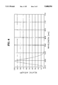
- FIG. 6 is an emission spectrum of a red emitting phosphor of 3.5MgO.0.5MgF 2 .GeO 2 :Mn when is excited by 394 nm light.
- the preferred backlight source is a lamp which includes at least one deep blue emitting phosphor selected from the group consisting of SrP 2 O 7 :Eu (420 nm), SrMgP 2 O 7 :Eu (394 nm), Sr 3 (PO 4 ) 2 :Eu (408 nm), (Sr,Ba)Al 2 Si 2 O 8 :Eu (400 nm), Y 2 Si 2 O 7 :Ce (385 nm), ZnGa 2 O 4 :Li,Ti (380 nm), YTaO 4 :Nb (400 nm), CaWO 4 (410 nm), BaFX:Eu (wherein X represents halogen, 380 nm), (Sr,Ca)O.2B 2 O 3 :Eu (380-450 nm), SrAl 12 O 14 :Eu (400 nm) and Y 2 SiO 5 :Ce (400 nm).
- FIG. 3 An emission spectrum of SrMgP 2 O 7 :Eu among the above-mentioned phosphors is illustrated in FIG. 3 when is excited by 254 nm ultraviolet.
- the preferred phosphor includes at least one blue emitting phosphor selected from the group consisting of Sr 10 (PO 4 ) 6 Cl 2 :Eu 2+ (447 nm), (Sr 0 .9 Ca 0 .1) 10 (PO 4 ) 6 Cl 2 :Eu (452 nm), Ba 3x Sr x Si 2 O 8 :Eu (450 nm), Ba 3-x Sr x Si 2 O 8 :Eu (x is 0 ⁇ 3, 440 ⁇ 460 nm), Ba 5 SiO 4 Cl 6 :Eu (440 nm), ZnS:Ag,Cl, ZnS:Ag,Al, ZnS:Ag and ZnS:Ag,Ga; at least one green emitting phosphor selected from the group consisting of SrAl 2 O 4 :Eu (520 nm), SrGa 2 S 4 :Eu (518 nm), Ca 3 SiO 4 Cl 2 :Eu (510 nm), Ba 2-
- FIGS. 4-6 emission spectrums of blue (Sr 10 (PO 4 ) 6 Cl 2 :Eu), green (SrGa 2 S 4 :Eu) and red (3.5MgO.0.5MgF 2 .GeO 2 :Mn) emitting phosphors among the above-mentioned phosphors are illustrated when are excited by 394 nm deep blue light. An appropriate selection among the blue, green and red phosphors will give color display device having good characteristics.
- the display device is further provided with a backlight-transmitting mirror for reflecting the emitted light in all directions from the phosphors, forwardly through the device, to improve the emitting efficiency.
- the backlight-transmitting mirror transmits the backlight, while reflecting the light emitted from the phosphors.
- the display device of the present invention employs light in the deep blue region as a backlight source instead of the white light, and phosphors being stimulated by the light of the deep blue region instead of a color filter, to greatly improve viewing angle and luminance.
- the light passed through the conventional optoelectronic device which has color filter is transmitted straight, while the light emitted from the phosphors of the present invention has the characteristics of omnidirectional emission, to thereby improve the viewing angle.
- the backlight does not go through a color filter, the amount of light attenuation caused from the color filter can be reduced, resulting in a net increase in luminance.
- the deep blue region light is selected considering that the liquid crystal in an LCD is liable to be chemically changed by the ultraviolet light, the ultraviolet light does not transmit the PLZT and the intensity of the transmitted light is weakened when near ultraviolet lamp is used.
- the backlight source used in the present invention emits light of the wavelength region 380-420 nm.
- the wavelength is less than 380 nm and the optoelectronic material is liquid crystal, the liquid crystal material is decomposed.
- the wavelength is less than 380 nm and PLZT is used, ultraviolet cut-off is induced so that the light intensity to stimulate the phosphors in the front side is too weak.
- the wavelength exceeds 420 nm, the color reproduction range is too narrow.
- the phosphor can be employed in the display device of the present invention using a method similar to that applied in forming a phosphor layer of the conventional CRT.
- a black matrix pattern layer is provided to absorb the external light and a phosphor layer is formed between the black matrix patterns which emits light of each color by the backlight.
- the black matrix is formed as a light absorbing graphite layer by a photoresist method.
- a photoresist pattern is formed by washing the inside of a substrate, coating a photoresist comprising polyvinyl alcohol, sodium dichromate, a polymer of propylene oxide and ethylene oxide, acryl emulsion and pure water, on the inner surface of the substrate, drying and developing the coated substrate.
- Graphite is coated on the surface of the substrate where photoresist pattern is formed and is etched using hydrogen peroxide to remove the photoresist and to thereby form the black matrix layer. Then, on the surface of the black matrix layer, a phosphor slurry including phosphor particles of a first type, pure water and polyvinyl alcohol is coated, dried, exposed, developed, washed and dried to form a first phosphor layer. A second phosphor layer and a third phosphor layer are subsequently formed according to the same method, to form a phosphor layer having three color emitting phosphors.
- FIG. 2 schematically illustrates a preferred display device according to an embodiment of the present invention.
- a backlight 1' in the back side (the left side in the drawing) emits deep blue region light
- a polarizer 2 selects only light having a prescribed direction among the backlight
- an analyzer 6 receives the selected light.
- latitudinal electrode 3 optoelectronic material 4
- longitudinal electrodes 5 are provided between the polarizer 2 and the analyzer 6, and longitudinal electrodes 5 are provided.
- a phosphor pattern 8 and a black matrix 9 are formed on the substrate 10 such as glass.
- the display device of the present invention is provided with a phosphor layer emitting each color instead of the color filter of the conventional device.
- the light emitted from the backlight and transmitted via the polarizer passes through the optoelectronic material via a different path in accordance with whether a voltage is applied to a pair of transparent electrodes or not.
- the transmitted light is transmitted or cut off by the analyzer.
- the transmitted light stimulates the prescribed phosphor on the phosphor layer and the stimulated phosphor emits light of the corresponding wavelength in all directions.
- the display device of the present invention reproduces each color by using the phosphors for emitting color light omnidirectionally and a light source for stimulating the phosphor, the device has an improved viewing angle and increased luminance when compared with the conventional display device.
- the display device of the present invention is novel and can replace an optoelectronic display such as an STN-type LCD, a TFT-type LCD, an FLCD or PLZT device.
Abstract
Description
Claims (9)
Applications Claiming Priority (2)
| Application Number | Priority Date | Filing Date | Title |
|---|---|---|---|
| KR1019940018087A KR100315106B1 (en) | 1994-07-26 | 1994-07-26 | Display device |
| KR94-18087 | 1994-07-26 |
Publications (1)
| Publication Number | Publication Date |
|---|---|
| US5608554A true US5608554A (en) | 1997-03-04 |
Family
ID=19388835
Family Applications (1)
| Application Number | Title | Priority Date | Filing Date |
|---|---|---|---|
| US08/385,514 Expired - Lifetime US5608554A (en) | 1994-07-26 | 1995-02-08 | LCD having a phosphor layer and a backlight source with a main emitting peak in the region of 380-420nm |
Country Status (9)
| Country | Link |
|---|---|
| US (1) | US5608554A (en) |
| JP (1) | JPH0862602A (en) |
| KR (1) | KR100315106B1 (en) |
| CN (1) | CN1116753A (en) |
| DE (1) | DE19504421A1 (en) |
| GB (1) | GB2291734B (en) |
| MY (1) | MY111817A (en) |
| NL (1) | NL9500287A (en) |
| TW (1) | TW296439B (en) |
Cited By (30)
| Publication number | Priority date | Publication date | Assignee | Title |
|---|---|---|---|---|
| WO2000014598A1 (en) * | 1998-09-04 | 2000-03-16 | Screen Technology Limited | Phosphor arrangement for liquid-crystal displays |
| US6178018B1 (en) | 1999-06-25 | 2001-01-23 | International Business Machines Corporation | Process and method employing dynamic holographic display medium |
| US6243151B1 (en) * | 1997-07-31 | 2001-06-05 | Nec Corporation | Liquid crystal display with polarization layer interior to substrates |
| US20010043294A1 (en) * | 2000-01-14 | 2001-11-22 | Helmut Bechtel | Liquid crystal color display screen comprising a phosphor layer |
| US20020060908A1 (en) * | 2000-01-31 | 2002-05-23 | Steven Doe | Electronic display |
| US20020145685A1 (en) * | 2001-04-04 | 2002-10-10 | Regina Mueller-Mach | Blue backlight and phosphor layer for a color LCD |
| EP1256835A2 (en) * | 2001-05-10 | 2002-11-13 | LumiLeds Lighting U.S., LLC | Backlight for a color LCD |
| US20030141800A1 (en) * | 1999-02-24 | 2003-07-31 | Koninklijke Philips Electronics N.V. | Display device comprising a light guide |
| EP1403355A1 (en) * | 2002-09-24 | 2004-03-31 | General Electric Company | Phosphor blends and blacklight sources for liquid crystal displays |
| US6717348B2 (en) | 1999-12-09 | 2004-04-06 | Fuji Photo Film Co., Ltd. | Display apparatus |
| US6819041B2 (en) * | 2000-02-25 | 2004-11-16 | Sony Corporation | Luminescence crystal particle, luminescence crystal particle composition, display panel and flat-panel display |
| US20040227465A1 (en) * | 2003-05-17 | 2004-11-18 | Hisham Menkara | Light emitting device having silicate fluorescent phosphor |
| KR100457864B1 (en) * | 2002-02-23 | 2004-11-18 | 삼성전기주식회사 | Phosphor for white LED lamp |
| KR100458126B1 (en) * | 2002-01-11 | 2004-11-20 | 한국화학연구원 | Green-emitting phosphor for long wavelength ultraviolet and a preparation method thereof |
| US7036946B1 (en) * | 2002-09-13 | 2006-05-02 | Rockwell Collins, Inc. | LCD backlight with UV light-emitting diodes and planar reactive element |
| US20060147148A1 (en) * | 2005-01-05 | 2006-07-06 | Shih-Yuan Wang | Method and apparatus for pixel display and SERS analysis |
| US20060152646A1 (en) * | 2002-08-21 | 2006-07-13 | Martin Schrader | Switchable lens display |
| US20060238103A1 (en) * | 2005-04-25 | 2006-10-26 | Samsung Electronics Co., Ltd. | Photo-luminescence liquid crystal display |
| US20060238671A1 (en) * | 2005-04-20 | 2006-10-26 | Samsung Electronics Co., Ltd. | Photo-luminescence liquid crystal display |
| US20060256253A1 (en) * | 2005-05-10 | 2006-11-16 | Dae-Jin Park | Liquid crystal display |
| US20060274226A1 (en) * | 2005-06-02 | 2006-12-07 | Samsung Electronics Co., Ltd. | Photo-luminescent liquid crystal display |
| US20070099095A1 (en) * | 2004-03-20 | 2007-05-03 | Hewlett-Packard Development Company, L.P. | Applying colour elements and busbars to a display substrate |
| US20070125982A1 (en) * | 2005-12-02 | 2007-06-07 | Sarnoff Corporation | Metal silicate halide phosphors and LED lighting devices using the same |
| US20090140630A1 (en) | 2005-03-18 | 2009-06-04 | Mitsubishi Chemical Corporation | Light-emitting device, white light-emitting device, illuminator, and image display |
| US20110128471A1 (en) * | 2008-07-07 | 2011-06-02 | James Rowland Suckling | Illumination panel and display |
| US20130106922A1 (en) * | 2011-10-28 | 2013-05-02 | Au Optronics Corporation | Transparent Display Device and Display Method Thereof |
| US8514352B2 (en) | 2010-12-10 | 2013-08-20 | Sharp Kabushiki Kaisha | Phosphor-based display |
| US9799804B2 (en) | 2014-10-28 | 2017-10-24 | Matrix Lighting Ltd. | Light-emitting device with near full spectrum light output |
| US9915775B2 (en) * | 2013-08-29 | 2018-03-13 | Soraa, Inc. | Circadian-friendly LED light sources |
| US10067386B2 (en) | 2014-09-30 | 2018-09-04 | Corning Incorporated | Devices comprising convex color converting elements |
Families Citing this family (21)
| Publication number | Priority date | Publication date | Assignee | Title |
|---|---|---|---|---|
| KR100200663B1 (en) * | 1996-03-20 | 1999-06-15 | 손욱 | Back-light device for lcd |
| GB9606659D0 (en) * | 1996-03-29 | 1996-06-05 | Screen Tech Ltd | Excitation of emissive displays |
| GB9726570D0 (en) * | 1997-12-16 | 1998-02-11 | Screen Tech Ltd | Liquid-crystal display using UV light source |
| JPH11237632A (en) * | 1998-02-24 | 1999-08-31 | Sharp Corp | Fluorescence type liquid crystal display device |
| US6429583B1 (en) * | 1998-11-30 | 2002-08-06 | General Electric Company | Light emitting device with ba2mgsi2o7:eu2+, ba2sio4:eu2+, or (srxcay ba1-x-y)(a1zga1-z)2sr:eu2+phosphors |
| JP2002023145A (en) * | 2000-07-12 | 2002-01-23 | Nec Corp | Liquid crystal display device |
| CN100489623C (en) * | 2003-07-26 | 2009-05-20 | 鸿富锦精密工业(深圳)有限公司 | Backlight source device |
| JP4663247B2 (en) * | 2004-02-18 | 2011-04-06 | パナソニック電工株式会社 | Indoor lighting device and light source used therefor |
| US7724321B2 (en) * | 2004-09-24 | 2010-05-25 | Epistar Corporation | Liquid crystal display |
| JP2005244259A (en) * | 2005-05-23 | 2005-09-08 | Nichia Chem Ind Ltd | Light emitting diode |
| CN100353214C (en) * | 2005-06-06 | 2007-12-05 | 浙江大学 | Coplanar electrode type piezoelectric ceramic material optical circular polarizing modulator |
| KR20070029526A (en) * | 2005-09-10 | 2007-03-14 | 삼성전자주식회사 | Photoluminescent liquid crystal display |
| JP2007308537A (en) * | 2006-05-16 | 2007-11-29 | Sony Corp | Luminous composition, light source unit and display |
| DE102007020782A1 (en) * | 2006-09-27 | 2008-04-03 | Osram Opto Semiconductors Gmbh | Radiation emitting device comprises a radiation-emitting functional layer emitting primary radiation in blue region, radiation conversion material arranged in beam path of the functional layer, and radiation conversion luminescent material |
| CN101605867B (en) * | 2006-10-03 | 2013-05-08 | 渲染材料公司 | Metal silicate halide phosphors and led lighting devices using the same |
| JP2009046668A (en) | 2007-08-21 | 2009-03-05 | Samsung Sdi Co Ltd | White phosphor, light emitting device and display device using the same |
| CN102356348A (en) * | 2009-03-19 | 2012-02-15 | 夏普株式会社 | Display panel and display device |
| JP5574359B2 (en) * | 2009-03-27 | 2014-08-20 | 株式会社ジャパンディスプレイ | Liquid crystal display |
| KR101436123B1 (en) * | 2013-07-09 | 2014-11-03 | 피에스아이 주식회사 | Display including nano-scale LED and method for manufacturing thereof |
| CN105428550B (en) * | 2015-12-22 | 2018-12-18 | 昆山国显光电有限公司 | A kind of organic electroluminescence device |
| CN113593445B (en) * | 2021-06-29 | 2023-04-07 | 盒马(中国)有限公司 | Polarized light indication strip, polarizer, polarized light indication system, data processing method and device |
Citations (13)
| Publication number | Priority date | Publication date | Assignee | Title |
|---|---|---|---|---|
| US4470666A (en) * | 1979-06-18 | 1984-09-11 | General Motors Corporation | Colored liquid crystal display |
| JPS6061725A (en) * | 1983-09-16 | 1985-04-09 | Sharp Corp | Color liquid crystal display device |
| JPS60149028A (en) * | 1984-01-13 | 1985-08-06 | Ricoh Co Ltd | Liquid crystal color display device |
| JPS61169824A (en) * | 1985-01-23 | 1986-07-31 | Ricoh Co Ltd | Polarizing plate for transmission type liquid crystal display device |
| US4678285A (en) * | 1984-01-13 | 1987-07-07 | Ricoh Company, Ltd. | Liquid crystal color display device |
| US4772885A (en) * | 1984-11-22 | 1988-09-20 | Ricoh Company, Ltd. | Liquid crystal color display device |
| US4793691A (en) * | 1984-12-25 | 1988-12-27 | Ricoh Company, Ltd. | Liquid crystal color display device |
| JPH03116022A (en) * | 1989-09-28 | 1991-05-17 | Toshiba Corp | Liquid crystal display panel |
| US5231328A (en) * | 1987-06-22 | 1993-07-27 | Kasei Optonix, Ltd. | Phosphor and ultraviolet ray excited fluorescent tube employing it |
| US5233459A (en) * | 1991-03-06 | 1993-08-03 | Massachusetts Institute Of Technology | Electric display device |
| EP0587123A2 (en) * | 1992-09-07 | 1994-03-16 | Kasei Optonix, Ltd. | Pigment-attached blue-emitting phosphor and color cathode-ray tube |
| JPH06222360A (en) * | 1993-01-27 | 1994-08-12 | Seiko Epson Corp | Liquid crystal display device |
| US5374493A (en) * | 1991-09-05 | 1994-12-20 | International Business Machines Corporation | Color filter and method of fabricating a color filter |
Family Cites Families (29)
| Publication number | Priority date | Publication date | Assignee | Title |
|---|---|---|---|---|
| JPS60141782A (en) * | 1983-12-29 | 1985-07-26 | Fuji Photo Film Co Ltd | Conversion of radiation image |
| JPH0762749B2 (en) * | 1986-02-20 | 1995-07-05 | 松下電器産業株式会社 | Emissive display device |
| US4641925A (en) * | 1986-03-20 | 1987-02-10 | Motorola, Inc. | Liquid crystal display assembly with phosphorescent backlighting |
| US4799050A (en) * | 1986-10-23 | 1989-01-17 | Litton Systems Canada Limited | Full color liquid crystal display |
| US5146355A (en) * | 1986-10-23 | 1992-09-08 | Litton Systems Canada Limited | Transflective mode liquid crystal display with phosphor illumination |
| JPS63135481A (en) * | 1986-11-28 | 1988-06-07 | Futaba Corp | Phosphor excited with electron beam |
| CA1274613A (en) * | 1986-12-24 | 1990-09-25 | Leendert Vriens | Projection device and associated display device |
| US4822144A (en) * | 1986-12-24 | 1989-04-18 | U.S. Philips Corporation | Electro-optic color display including luminescent layer and interference filter |
| JPH0747732B2 (en) * | 1987-12-05 | 1995-05-24 | 日亜化学工業株式会社 | Slow electron beam excited phosphor |
| JPH02503717A (en) * | 1988-03-07 | 1990-11-01 | 富士通株式会社 | X-ray image conversion sheet, method for producing X-ray image conversion sheet, stimulable phosphor, and method for producing stimulable phosphor |
| JP2532586B2 (en) * | 1988-06-17 | 1996-09-11 | 日亜化学工業株式会社 | Slow electron beam excited phosphor and method for producing the same |
| US4872741A (en) * | 1988-07-22 | 1989-10-10 | General Electric Company | Electrodeless panel discharge lamp liquid crystal display |
| CA2000388A1 (en) * | 1988-11-14 | 1990-05-14 | John Colin Prince | Full color liquid crystal display |
| JPH0747733B2 (en) * | 1988-12-28 | 1995-05-24 | 双葉電子工業株式会社 | Blue light emitting phosphor |
| JP2751413B2 (en) * | 1989-06-02 | 1998-05-18 | ソニー株式会社 | Phosphor screen for cathode ray tube |
| US4940918A (en) * | 1989-07-24 | 1990-07-10 | Gte Products Corporation | Fluorescent lamp for liquid crystal backlighting |
| AU6885391A (en) * | 1989-11-24 | 1991-06-26 | Innovare Limited | A display device |
| JPH0711949B2 (en) * | 1989-12-20 | 1995-02-08 | 東芝ライテック株式会社 | Fluorescent lamp and lamp device using the same |
| US5009807A (en) * | 1990-01-02 | 1991-04-23 | Gte Products Corporation | Niobium-activated yttrium tantalate x-ray phosphor with improved brightness and method of making same |
| JP2784255B2 (en) * | 1990-10-02 | 1998-08-06 | 日亜化学工業株式会社 | Phosphor and discharge lamp using the same |
| US5069982A (en) * | 1990-11-19 | 1991-12-03 | E. I. Du Pont De Nemours And Company | Mixed phosphor x-ray intensifying screens with improved resolution |
| JPH04188557A (en) * | 1990-11-20 | 1992-07-07 | Matsushita Electron Corp | High-pressure fluorescent mercury lamp |
| FR2679049A1 (en) * | 1991-07-09 | 1993-01-15 | Thomson Csf | COLOR VISUALIZATION SYSTEM. |
| WO1993004393A1 (en) * | 1991-08-19 | 1993-03-04 | Smiths Industries, Inc. | Improved lighting technique for color displays |
| US5267062A (en) * | 1991-08-26 | 1993-11-30 | Rockwell International Corporation | System for backlighting LCD matrices including luminescent dots each followed by and at the focal point of a lens |
| JP2783058B2 (en) * | 1992-03-25 | 1998-08-06 | 日亜化学工業株式会社 | Phosphor composition |
| DE69300721T2 (en) * | 1992-06-10 | 1996-05-30 | Agfa Gevaert Nv | Photo-stimulable storage phosphor and its use in radiography. |
| JP3263991B2 (en) * | 1992-07-10 | 2002-03-11 | 化成オプトニクス株式会社 | Blue light emitting phosphor |
| GB9406742D0 (en) * | 1994-04-06 | 1994-05-25 | Crossland William A | Thin panel display screen |
-
1994
- 1994-07-26 KR KR1019940018087A patent/KR100315106B1/en not_active IP Right Cessation
-
1995
- 1995-01-26 JP JP7010631A patent/JPH0862602A/en active Pending
- 1995-01-27 MY MYPI95000204A patent/MY111817A/en unknown
- 1995-02-08 US US08/385,514 patent/US5608554A/en not_active Expired - Lifetime
- 1995-02-10 DE DE19504421A patent/DE19504421A1/en not_active Withdrawn
- 1995-02-14 GB GB9502880A patent/GB2291734B/en not_active Expired - Lifetime
- 1995-02-14 TW TW084101333A patent/TW296439B/zh not_active IP Right Cessation
- 1995-02-16 NL NL9500287A patent/NL9500287A/en active Search and Examination
- 1995-02-23 CN CN95102274A patent/CN1116753A/en active Pending
Patent Citations (13)
| Publication number | Priority date | Publication date | Assignee | Title |
|---|---|---|---|---|
| US4470666A (en) * | 1979-06-18 | 1984-09-11 | General Motors Corporation | Colored liquid crystal display |
| JPS6061725A (en) * | 1983-09-16 | 1985-04-09 | Sharp Corp | Color liquid crystal display device |
| JPS60149028A (en) * | 1984-01-13 | 1985-08-06 | Ricoh Co Ltd | Liquid crystal color display device |
| US4678285A (en) * | 1984-01-13 | 1987-07-07 | Ricoh Company, Ltd. | Liquid crystal color display device |
| US4772885A (en) * | 1984-11-22 | 1988-09-20 | Ricoh Company, Ltd. | Liquid crystal color display device |
| US4793691A (en) * | 1984-12-25 | 1988-12-27 | Ricoh Company, Ltd. | Liquid crystal color display device |
| JPS61169824A (en) * | 1985-01-23 | 1986-07-31 | Ricoh Co Ltd | Polarizing plate for transmission type liquid crystal display device |
| US5231328A (en) * | 1987-06-22 | 1993-07-27 | Kasei Optonix, Ltd. | Phosphor and ultraviolet ray excited fluorescent tube employing it |
| JPH03116022A (en) * | 1989-09-28 | 1991-05-17 | Toshiba Corp | Liquid crystal display panel |
| US5233459A (en) * | 1991-03-06 | 1993-08-03 | Massachusetts Institute Of Technology | Electric display device |
| US5374493A (en) * | 1991-09-05 | 1994-12-20 | International Business Machines Corporation | Color filter and method of fabricating a color filter |
| EP0587123A2 (en) * | 1992-09-07 | 1994-03-16 | Kasei Optonix, Ltd. | Pigment-attached blue-emitting phosphor and color cathode-ray tube |
| JPH06222360A (en) * | 1993-01-27 | 1994-08-12 | Seiko Epson Corp | Liquid crystal display device |
Non-Patent Citations (6)
| Title |
|---|
| "Cathodoluminescent Backlight For Liquid Crystal Displays", Research Disclosure, Jan. 1991, No. 321, Kenneth Mason Publications Ltd, England. |
| Cathodoluminescent Backlight For Liquid Crystal Displays , Research Disclosure, Jan. 1991, No. 321, Kenneth Mason Publications Ltd, England. * |
| Patent Abstracts Of Japan, "Color Cathode Ray Tube Responsive To Light Pen", Ishii, Jun. 1993, [JP 60-4585]. |
| Patent Abstracts Of Japan, "Phosphor Screen For Cathode Ray Tube", Kusuki et al, Jun. 1989, [JP 03-6290]. |
| Patent Abstracts Of Japan, Color Cathode Ray Tube Responsive To Light Pen , Ishii, Jun. 1993, JP 60 4585 . * |
| Patent Abstracts Of Japan, Phosphor Screen For Cathode Ray Tube , Kusuki et al, Jun. 1989, JP 03 6290 . * |
Cited By (58)
| Publication number | Priority date | Publication date | Assignee | Title |
|---|---|---|---|---|
| US6445431B2 (en) | 1997-07-31 | 2002-09-03 | Nec Corporation | Liquid crystal display with polarization layer interior to substrates |
| US6501520B2 (en) * | 1997-07-31 | 2002-12-31 | Nec Corporation | Liquid crystal display with polarization layer interior to substrates |
| US6243151B1 (en) * | 1997-07-31 | 2001-06-05 | Nec Corporation | Liquid crystal display with polarization layer interior to substrates |
| WO2000014598A1 (en) * | 1998-09-04 | 2000-03-16 | Screen Technology Limited | Phosphor arrangement for liquid-crystal displays |
| US6908217B2 (en) * | 1999-02-24 | 2005-06-21 | Koninklijke Philips Electronics N.V. | Display device comprising a light guide |
| US20030141800A1 (en) * | 1999-02-24 | 2003-07-31 | Koninklijke Philips Electronics N.V. | Display device comprising a light guide |
| US6178018B1 (en) | 1999-06-25 | 2001-01-23 | International Business Machines Corporation | Process and method employing dynamic holographic display medium |
| US6717348B2 (en) | 1999-12-09 | 2004-04-06 | Fuji Photo Film Co., Ltd. | Display apparatus |
| US20010043294A1 (en) * | 2000-01-14 | 2001-11-22 | Helmut Bechtel | Liquid crystal color display screen comprising a phosphor layer |
| US6654079B2 (en) * | 2000-01-14 | 2003-11-25 | Koninklijke Philips Electronics N.V. | Liquid crystal color display screen comprising a phosphor layer |
| US20020060908A1 (en) * | 2000-01-31 | 2002-05-23 | Steven Doe | Electronic display |
| US6819041B2 (en) * | 2000-02-25 | 2004-11-16 | Sony Corporation | Luminescence crystal particle, luminescence crystal particle composition, display panel and flat-panel display |
| GB2371911A (en) * | 2001-01-31 | 2002-08-07 | Nokia Mobile Phones Ltd | Electronic Display |
| US20020145685A1 (en) * | 2001-04-04 | 2002-10-10 | Regina Mueller-Mach | Blue backlight and phosphor layer for a color LCD |
| US7248310B2 (en) | 2001-04-04 | 2007-07-24 | Philips Lumileds Lighting Company, Llc | Flat panel energized by blue LED for generating white light |
| US6844903B2 (en) * | 2001-04-04 | 2005-01-18 | Lumileds Lighting U.S., Llc | Blue backlight and phosphor layer for a color LCD |
| US20050104076A1 (en) * | 2001-04-04 | 2005-05-19 | Regina Mueller-Mach | Flat panel energized by blue LED for generating white light |
| US20020167624A1 (en) * | 2001-05-10 | 2002-11-14 | Steven Paolini | Backlight for a color LCD |
| US6791636B2 (en) | 2001-05-10 | 2004-09-14 | Lumilecs Lighting U.S., Llc | Backlight for a color LCD |
| EP1256835A2 (en) * | 2001-05-10 | 2002-11-13 | LumiLeds Lighting U.S., LLC | Backlight for a color LCD |
| EP1256835A3 (en) * | 2001-05-10 | 2005-04-20 | LumiLeds Lighting U.S., LLC | Backlight for a color LCD |
| KR100458126B1 (en) * | 2002-01-11 | 2004-11-20 | 한국화학연구원 | Green-emitting phosphor for long wavelength ultraviolet and a preparation method thereof |
| KR100457864B1 (en) * | 2002-02-23 | 2004-11-18 | 삼성전기주식회사 | Phosphor for white LED lamp |
| US20060152646A1 (en) * | 2002-08-21 | 2006-07-13 | Martin Schrader | Switchable lens display |
| US7036946B1 (en) * | 2002-09-13 | 2006-05-02 | Rockwell Collins, Inc. | LCD backlight with UV light-emitting diodes and planar reactive element |
| EP1403355A1 (en) * | 2002-09-24 | 2004-03-31 | General Electric Company | Phosphor blends and blacklight sources for liquid crystal displays |
| KR100915184B1 (en) * | 2002-09-24 | 2009-09-02 | 제너럴 일렉트릭 캄파니 | Phosphor blends and backlight sources for liquid crystal displays |
| CN100426072C (en) * | 2002-09-24 | 2008-10-15 | 通用电气公司 | Phosphor mixture and back light source for liquid crystal display |
| US6809781B2 (en) | 2002-09-24 | 2004-10-26 | General Electric Company | Phosphor blends and backlight sources for liquid crystal displays |
| US20040227465A1 (en) * | 2003-05-17 | 2004-11-18 | Hisham Menkara | Light emitting device having silicate fluorescent phosphor |
| WO2004111156A1 (en) * | 2003-05-17 | 2004-12-23 | Phosphortech Corporation | Light emitting devices having silicate fluorescent phosphors |
| US6982045B2 (en) * | 2003-05-17 | 2006-01-03 | Phosphortech Corporation | Light emitting device having silicate fluorescent phosphor |
| US7897303B2 (en) | 2004-03-20 | 2011-03-01 | Hewlett-Packard Development Company, L.P. | Applying color elements and busbars to a display substrate |
| US20070099095A1 (en) * | 2004-03-20 | 2007-05-03 | Hewlett-Packard Development Company, L.P. | Applying colour elements and busbars to a display substrate |
| US7609376B2 (en) | 2005-01-05 | 2009-10-27 | Hewlett-Packard Development Company, L.P. | Method and apparatus for pixel display and SERS analysis |
| US20060147148A1 (en) * | 2005-01-05 | 2006-07-06 | Shih-Yuan Wang | Method and apparatus for pixel display and SERS analysis |
| US9028718B2 (en) | 2005-03-18 | 2015-05-12 | Mitsubishi Chemical Corporation | Light-emitting device, white light-emitting device, illuminator, and image display |
| US8269410B2 (en) | 2005-03-18 | 2012-09-18 | Mitsubishi Chemical Corporation | Light-emitting device, white light-emitting device, illuminator, and image display |
| US20090140630A1 (en) | 2005-03-18 | 2009-06-04 | Mitsubishi Chemical Corporation | Light-emitting device, white light-emitting device, illuminator, and image display |
| US20060238671A1 (en) * | 2005-04-20 | 2006-10-26 | Samsung Electronics Co., Ltd. | Photo-luminescence liquid crystal display |
| US20060238103A1 (en) * | 2005-04-25 | 2006-10-26 | Samsung Electronics Co., Ltd. | Photo-luminescence liquid crystal display |
| US20060256253A1 (en) * | 2005-05-10 | 2006-11-16 | Dae-Jin Park | Liquid crystal display |
| US20060274226A1 (en) * | 2005-06-02 | 2006-12-07 | Samsung Electronics Co., Ltd. | Photo-luminescent liquid crystal display |
| US7746423B2 (en) * | 2005-06-02 | 2010-06-29 | Samsung Electronics Co., Ltd. | Photo-luminescent liquid crystal display including a blue dichroic mirror layer |
| US8906262B2 (en) | 2005-12-02 | 2014-12-09 | Lightscape Materials, Inc. | Metal silicate halide phosphors and LED lighting devices using the same |
| EP1969085A1 (en) * | 2005-12-02 | 2008-09-17 | Sarnoff Corporation | Metal silicate halide phosphors and led lighting devices using the same |
| WO2007064414A1 (en) | 2005-12-02 | 2007-06-07 | Sarnoff Corporation | Metal silicate halide phosphors and led lighting devices using the same |
| US20070125982A1 (en) * | 2005-12-02 | 2007-06-07 | Sarnoff Corporation | Metal silicate halide phosphors and LED lighting devices using the same |
| EP1969085A4 (en) * | 2005-12-02 | 2009-12-02 | Lightscape Materials Inc | Metal silicate halide phosphors and led lighting devices using the same |
| US20110128471A1 (en) * | 2008-07-07 | 2011-06-02 | James Rowland Suckling | Illumination panel and display |
| US8514352B2 (en) | 2010-12-10 | 2013-08-20 | Sharp Kabushiki Kaisha | Phosphor-based display |
| US20130106922A1 (en) * | 2011-10-28 | 2013-05-02 | Au Optronics Corporation | Transparent Display Device and Display Method Thereof |
| US9829757B2 (en) | 2011-10-28 | 2017-11-28 | Au Optronics Corporation | Transparent display device and display method thereof |
| US9915775B2 (en) * | 2013-08-29 | 2018-03-13 | Soraa, Inc. | Circadian-friendly LED light sources |
| US10955608B2 (en) | 2013-08-29 | 2021-03-23 | EcoSense Lighting, Inc. | Circadian-friendly LED light sources |
| US11511071B2 (en) | 2013-08-29 | 2022-11-29 | Korrus, Inc. | Circadian-friendly LED light sources |
| US10067386B2 (en) | 2014-09-30 | 2018-09-04 | Corning Incorporated | Devices comprising convex color converting elements |
| US9799804B2 (en) | 2014-10-28 | 2017-10-24 | Matrix Lighting Ltd. | Light-emitting device with near full spectrum light output |
Also Published As
| Publication number | Publication date |
|---|---|
| TW296439B (en) | 1997-01-21 |
| KR100315106B1 (en) | 2002-02-19 |
| JPH0862602A (en) | 1996-03-08 |
| GB2291734A (en) | 1996-01-31 |
| GB9502880D0 (en) | 1995-04-05 |
| GB2291734B (en) | 1998-07-08 |
| CN1116753A (en) | 1996-02-14 |
| DE19504421A1 (en) | 1996-02-01 |
| NL9500287A (en) | 1996-03-01 |
| MY111817A (en) | 2001-01-31 |
Similar Documents
| Publication | Publication Date | Title |
|---|---|---|
| US5608554A (en) | LCD having a phosphor layer and a backlight source with a main emitting peak in the region of 380-420nm | |
| TW579491B (en) | Liquid crystal display device and display device | |
| US4822144A (en) | Electro-optic color display including luminescent layer and interference filter | |
| US6445431B2 (en) | Liquid crystal display with polarization layer interior to substrates | |
| JP4310243B2 (en) | Liquid crystal display | |
| JPS63216029A (en) | Liquid crystal color display cell and color image display | |
| JP2001264759A (en) | Liquid crystal display screen | |
| JP2001242459A (en) | Liquid crystal color display screen | |
| JPH0762749B2 (en) | Emissive display device | |
| JPH0766124B2 (en) | Emissive display device | |
| KR100200663B1 (en) | Back-light device for lcd | |
| JP2003255320A (en) | Liquid crystal display | |
| KR100237218B1 (en) | Lcd device using fluorescent | |
| KR100307443B1 (en) | Lcd having fluorescent material layer including polarization element, liquid crystal cell and fluorescent material | |
| KR100382057B1 (en) | Plzt flat display panel and method for manufacturing the same | |
| KR100283568B1 (en) | Liquid crystal display | |
| JP2673348B2 (en) | Planar light emitting device | |
| KR100322444B1 (en) | Plzt display apparatus using fluorescent film layer | |
| JPH01230091A (en) | Color display device | |
| JPH09113937A (en) | Liquid crystal display device | |
| KR100315109B1 (en) | Liquid crystal display | |
| JP2003021831A (en) | Liquid crystal display device using fluorescent material | |
| JPS62194280A (en) | Luminescence type display unit | |
| JPH0614246B2 (en) | Emissive display device | |
| KR20000014977A (en) | Radiate-typed liquid crystal display apparatus |
Legal Events
| Date | Code | Title | Description |
|---|---|---|---|
| AS | Assignment |
Owner name: SAMSUNG DISPLAY DEVICES CO., LTD., JAPAN Free format text: ASSIGNMENT OF ASSIGNORS INTEREST;ASSIGNORS:DO, YOUNG-RAG;YOU, YOUNG-CHUL;JEONG, JOA-YOUNG;AND OTHERS;REEL/FRAME:007394/0143 Effective date: 19950112 |
|
| STCF | Information on status: patent grant |
Free format text: PATENTED CASE |
|
| FEPP | Fee payment procedure |
Free format text: PAYOR NUMBER ASSIGNED (ORIGINAL EVENT CODE: ASPN); ENTITY STATUS OF PATENT OWNER: LARGE ENTITY Free format text: PAYER NUMBER DE-ASSIGNED (ORIGINAL EVENT CODE: RMPN); ENTITY STATUS OF PATENT OWNER: LARGE ENTITY |
|
| FPAY | Fee payment |
Year of fee payment: 4 |
|
| FPAY | Fee payment |
Year of fee payment: 8 |
|
| FPAY | Fee payment |
Year of fee payment: 12 |
|
| AS | Assignment |
Owner name: SAMSUNG MOBILE DISPLAY CO., LTD., KOREA, REPUBLIC Free format text: ASSIGNMENT OF ASSIGNORS INTEREST;ASSIGNOR:SAMSUNG SDI CO., LTD.;REEL/FRAME:023620/0798 Effective date: 20091113 |
|
| AS | Assignment |
Owner name: SAMSUNG DISPLAY CO., LTD., KOREA, REPUBLIC OF Free format text: MERGER;ASSIGNOR:SAMSUNG MOBILE DISPLAY CO., LTD.;REEL/FRAME:029096/0174 Effective date: 20120827 |