US5606915A - Power and free conveying system - Google Patents
Power and free conveying system Download PDFInfo
- Publication number
- US5606915A US5606915A US08/418,214 US41821495A US5606915A US 5606915 A US5606915 A US 5606915A US 41821495 A US41821495 A US 41821495A US 5606915 A US5606915 A US 5606915A
- Authority
- US
- United States
- Prior art keywords
- trolley
- power
- free
- track
- dog
- Prior art date
- Legal status (The legal status is an assumption and is not a legal conclusion. Google has not performed a legal analysis and makes no representation as to the accuracy of the status listed.)
- Expired - Fee Related
Links
Images


Classifications
-
- B—PERFORMING OPERATIONS; TRANSPORTING
- B65—CONVEYING; PACKING; STORING; HANDLING THIN OR FILAMENTARY MATERIAL
- B65G—TRANSPORT OR STORAGE DEVICES, e.g. CONVEYORS FOR LOADING OR TIPPING, SHOP CONVEYOR SYSTEMS OR PNEUMATIC TUBE CONVEYORS
- B65G1/00—Storing articles, individually or in orderly arrangement, in warehouses or magazines
-
- E—FIXED CONSTRUCTIONS
- E01—CONSTRUCTION OF ROADS, RAILWAYS, OR BRIDGES
- E01B—PERMANENT WAY; PERMANENT-WAY TOOLS; MACHINES FOR MAKING RAILWAYS OF ALL KINDS
- E01B25/00—Tracks for special kinds of railways
- E01B25/22—Tracks for railways with the vehicle suspended from rigid supporting rails
- E01B25/24—Supporting rails; Auxiliary balancing rails; Supports or connections for rails
-
- B—PERFORMING OPERATIONS; TRANSPORTING
- B61—RAILWAYS
- B61B—RAILWAY SYSTEMS; EQUIPMENT THEREFOR NOT OTHERWISE PROVIDED FOR
- B61B10/00—Power and free systems
- B61B10/02—Power and free systems with suspended vehicles
-
- B—PERFORMING OPERATIONS; TRANSPORTING
- B61—RAILWAYS
- B61B—RAILWAY SYSTEMS; EQUIPMENT THEREFOR NOT OTHERWISE PROVIDED FOR
- B61B10/00—Power and free systems
- B61B10/02—Power and free systems with suspended vehicles
- B61B10/025—Coupling and uncoupling means between power track abd vehicles
Definitions
- the present invention relates generally to conveying systems and, more specifically, to a power and free conveying system.
- a power and free conveying system includes a power track, a free track, a power trolley supported on the power track for movement therealong and a free trolley to support a load on the free track.
- the power trolley is typically chain driven and engages and disengages the free trolley to move the free trolley along the free track from one assembly station to another.
- the present invention is a power and free conveying system including a track assembly having a power track and a free track spaced vertically from the power track.
- the power and free conveying system also includes a power trolley supported on the power track for movement therealong and a free trolley supported on the free track for movement therealong.
- the free trolley also includes a moveable holdback dog engageable and disengageable with the power trolley.
- the free trolley includes a retractable dog having a first position engageable with the power trolley and a second position disengageable with the power trolley and engageable with the holdback dog to completely disengage the free trolley from the power trolley upon engaging another free trolley.
- the track assembly includes a C-shaped first side support member having an upper transverse end connected to the power track and a lower transverse end connected to the free track.
- the track assembly also includes a C-shaped second side support member opposite and spaced from the first side support member having an upper transverse end connected to the power track and a lower transverse end connected to the free track.
- the power and free conveying system is modular in nature and allows the reuse of parts from one site to another or from one system in a building to another system in the building.
- the power and free conveying system's modular design greatly reduces cost, time and labor required for field installation and start-up.
- the power and free conveying system's modular design increases ease of installation, reliability and standardization.
- the power and free conveying system has a novel track assembly, pusher dogs, chain transfers and trolleys which overcome weaknesses in existing power and free conveyors.
- the free trolley has increased dog bite for more positive engagement with the chain, longer wheelbase for improved trolley stability and removable side guide rollers for ease of maintenance.
- the track assembly has a torsionally stiff guard support member on top of the track to prevent rail twist, common rails on both power and free tracks, and bolted track splices to eliminate field welding and reduce installation time. More features of the present invention are that the track assembly is able to span twenty-five feet without additional support and has double the carrying capacity of existing conveyors.
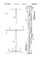
- FIG. 1 is a plan view of a power and free conveying system, according to the present invention, illustrated in a bay of a building.
- FIG. 2 is an enlarged front view of a portion of the power and free conveying system of FIG. 1.
- FIG. 3 is an enlarged fragmentary front view of a portion of the power and free conveying system of FIG. 1.
- FIG. 4 is a side view of the portion of the power and free conveying system of FIG. 3.
- FIG. 5 is a plan view of a transfer mechanism of the power and free conveying system of FIG. 1.
- FIG. 6 is a sectional view taken along line 6--6 of FIG. 5.
- FIG. 7 is a sectional view taken along line 7--7 of FIG. 5.
- FIG. 8 is a fragmentary front view of a portion of the power and free conveying system of FIG. 1 illustrating two trolleys before engagement.
- FIG. 9 is a view similar to FIG. 8 illustrating the two trolleys after engagement.
- a power and free conveying system 20 is illustrated in overhead relationship in a bay of a building.
- the power and free conveying system 20 may be supported in a typical forty (40) feet bay by two (2) headers 22 and four (4) hangers 24. It should be appreciated that only a portion of the power and free conveying system 10 is illustrated in FIG. 1.
- the power and free conveying system 20 includes a track assembly, generally indicated at 26, supported between the headers 22.
- the track assembly 26 includes a plurality of track yokes 28 installed on diagonals to form a truss to allow the track assembly 26 to span up to twenty-five (25) feet between the headers 22 overhead in the bay.
- the track assembly 26 also includes an upper guard support member 30 secured to the headers 22 by suitable means such as welding.
- the guard support member 30 is tubular and generally rectangular in cross-section.
- the guard support member 30 is torsionally stiff to prevent track or rail twist and eliminate additional supports.
- the track assembly 26 further includes at least one, preferably a plurality of first side support members 32 disposed along and secured to the upper support member 30.
- the first side support member 32 has a generally C-shaped cross-section and is secured to the guard support member 30 by suitable means such as welding.
- the track assembly 26 includes at least one, preferably a plurality of second side support member 34 spaced transversely from the first side support member 32 and disposed along and secured to the upper support member 30 opposite the first side support member 32.
- the second side support member 34 has a generally C-shaped cross-section and is secured to the guard support member 30 by suitable means such as welding. It should be appreciated that the track yokes 28 have a vertically orientated first and second side support member 32 and 34 at each end of the truss formed by the track yokes 28.
- the first side support member 32 includes a first or upper power track member or rail 36 at a transverse end of an upper portion thereof.
- the upper power track member 36 has a generally C-shaped cross-section with a flat interior wheel engaging or track surface 37 on a lower portion thereof for engagement by power trolley wheels 114 to be described.
- the first power track member 36 also has a downstanding flange 38 at a transverse end of the lower portion thereof.
- the first side support member 32 also includes a first or lower free track member 40 at a transverse end of a lower portion thereof.
- the first free track member 40 has a generally C-shaped cross-section with a flat interior wheel engaging or track surface 41 on a lower portion thereof for engagement by free trolley wheels 64,66 to be described.
- the first free track member 40 also has a downstanding flange 42 at a transverse end of the lower portion thereof.
- the second side support member 34 includes a second or upper power track member 44 at a transverse end of an upper portion thereof and spaced transversely from the first power track member 36.
- the second power track member 44 has a generally C-shaped cross-section with a flat interior wheel engaging or track surface 45 on a lower portion thereof for engagement by power trolley wheels 120 to be described.
- the second power track member 44 also has a downstanding flange 46 at a transverse end of the lower portion thereof.
- the second side support member 34 also includes a second or lower free track member 48 at a transverse end of a lower portion thereof and spaced transversely from the first free track member 40.
- the second free track member 48 has a generally C-shaped cross-section with a flat interior wheel engaging or track surface 49 on the lower portion thereof for engagement by free trolley wheels 68,70 to be described.
- the second free track member 48 also has a downstanding flange 50 at a transverse end of the lower portion thereof. It should be appreciated that the width of the free track is greater than the width of the power track for increased stability and that the track members 36,40,44,48 may be interchangeable.
- the track assembly 26 further includes track splices 52 to splice together pairs of sections thereof as illustrated in FIGS. 8 and 9.
- the track splices 52 are tubular and extend longitudinally.
- the track splices 52 are disposed beneath and abut the lower portion of each free track member 40,48 and the downstanding flange 42,50.
- the track splices 52 are secured to the first and second side support members 32 and 34 by fasteners 53 such as bolts 53a and nuts 53b. It should be appreciated that the track splices 52 eliminate field welding and reduce installation time.
- the power and free conveying system 10 also includes at least one, preferably a plurality of free trolleys, generally indicated at 54, for movement along the track assembly 26.
- the free trolley 54 has a trolley body 56 with transversely spaced first upstanding projections 58 and second upstanding projections 60 spaced longitudinally from the first upstanding projection 58 at an upper end thereof.
- the second upstanding projection 60 has a forward surface 62 fixed relative to the trolley body 56 for engagement with a stop blade (not shown).
- the free trolley 54 includes forward and rear first free trolley wheels 64 and 66, respectively, for engaging the first free track member 40 and forward and rear second free trolley wheels 68 and 70 respectively, for engaging the second free track member 48.
- Each of the trolley wheels 64,66, and 68,70 has a flat face to engage the track surfaces 41 and 49, respectively, and eliminate track spreading forces.
- Each of the free trolley wheels 64,66,68,70 are of the ball bearing type having a shaft 72 extending transversely through the trolley body 56 and secured thereto by nuts 74. It should be appreciated that any suitable means may be used to secure the free trolley wheels 64,66,68,70 to the trolley body 56. It should also be appreciated that the free trolley wheels 64,66,68,70 are easily removeable from the free trolley 54.
- the free trolley 54 may include forward and rear side guide rollers 76 and 78 disposed between the downstanding flanges 42 and 50 for engaging the downstanding flanges 42 and 50 of the first and second free track members 40 and 48, respectively.
- Each of the side guide rollers 76,78 are of the ball bearing type having a shaft 80 extending downwardly through the trolley body 56 and secured thereto by nuts 82. It should be appreciated that the side guide rollers 76,78 are removable for ease of maintenance.
- the free trolley 54 also includes a retractable dog 84 having a leg portion 86 extending downwardly through the trolley body 56.
- the retractable dog 84 has a cam face 87 and shoulder face 88 to engage a cam down bar 132 and chain pusher dog 126, respectively, to be described.
- the retractable dog 84 also has a dog portion 89 extending transversely a predetermined width for increased dog bite. It should be appreciated that the dog portion 89 is sufficiently wide to eliminate auxiliary devices at chain to chain transfers to be described.
- the leg portion 86 of the retractable dog 84 is disposed between a front force guide roll 90 and a rear force guide roll to prevent longitudinal movement thereof.
- the guide roll 90 is rotatably secured to the trolley body 56 by a pin 91. It should be appreciated that any suitable means may be used to rotatably secure guide roll 90 to the trolley body 56 to resist the retractable dog 84 from sticking in a retracted position.
- the free trolley 54 further includes an actuating lever 92 rotatably secured by a fastener 94 to a lower portion of the leg portion 86.
- the free trolley 54 includes a pair of side plates 96 secured to the trolley body 56 by fasteners 98.
- the actuating lever 92 is rotatably secured between the side plates 96 by suitable means such as a fastener 102. It should be appreciated that, when the actuating lever 92 is moved upwardly, the leg portion 86 moves downwardly to cause the retractable dog 84 to be retracted.
- the free trolley 54 also includes a holdback dog 104 rotatably secured between the projections 58 by suitable means such as a fastener 105.
- the holdback dog 104 has a dog portion 106 which may engage the chain pusher dog 106 to be described.
- the holdback dog 104 also has an actuated flange 107 which may be engaged by a corresponding actuator flange 108 of the leg portion 86 of the retractable dog 84 to rotate the holdback dog 104.
- the holdback dog 104 also has a cam surface 109 for engagement with a cam down bar 132 to be described to rotate the dog portion 106 downwardly. It should be appreciated that the retractable dog 84 and holdback dog 104 resist the chain pusher dog 106 from disengaging the free trolley 54.
- the power and free conveying system 10 includes at least one, preferably a plurality of power trolleys, generally indicated at 110, for movement along the track assembly 26.
- the power trolley 110 includes a first power trolley support 112 having a first power trolley wheel 114 rotatably secured to an upper portion thereof by suitable means such as a pin 116.
- the first power trolley wheel 114 has a flat face to engage the track surface 37 of the first power track member 36.
- the power trolley 110 also includes a second power trolley support 118 spaced transversely from the first power trolley support 112 and having a second power trolley wheel 120 rotatably secured to an upper portion thereof by suitable means such as a pin 116.
- the second power trolley wheel 120 has a flat face to engage the track surface 45 of the second power track member 44.
- the power trolley 110 also includes a chain 122 for engaging the power trolley supports 112,118.
- the power trolley supports 112,118 extend through the chain 122 and are secured to each other by suitable means such as fasteners 124 above and below the chain 122.
- the power trolley 110 also includes a chain dog pusher 126 disposed between a pair of power trolley supports 112,118 and secured to the chain 122 by suitable means such as fasteners 128.
- the chain dog pusher 126 engages the retractable dog 84 to move the free trolley 54 along the track assembly 26. It should be appreciated that the chain 122 is attached to a power source (not shown) to move the chain 122 along the track assembly 26.
- the power and free conveying system 10 may include at least one, preferably a pair of traction wheels 130 at a curved section of the track assembly 26. As illustrated, the traction wheels 130 are disposed along opposed curved sections of the power track to transfer the free trolley 54 from one power track to the other. As illustrated in FIG. 6, the wipe out power trolley 110 has the chain pusher dog 126 engaging the retractable dog 84 of the free trolley 54. As the chain 122 of the wipe out power trolley 110 moves in the direction indicated by the arrow A in FIG. 5, the cam surface 87 of the retractable dog 84 engages a cam down bar 132 disposed along the curved section of the wipe out power track and the retractable dog 84 moves downwardly or retracts.
- the chain pusher dog 126 of the wipe out power trolley 110 disengages the free trolley 54 and moves along the traction wheel 130.
- the wipe in power trolley 110 moves along the other traction wheel 130 and the cam down bar 132 ends to allow the retractable dog 84 to extend or move upwardly.
- the wipe in power trolley 110 has its chain pusher dog 126 engage the retractable dog 84 to move the free trolley 54 along the free tracks 40,48.
- FIGS. 5 through 7 illustrate a typical chain to chain transfer.
- the traction wheels 130 may have teeth on a circumference thereof to engage the chain 122.
- a pair of free trolleys 54 and 54' are illustrated before engagement on the power and free conveying system 10.
- a first free trolley 54 is shown with a king pin 140 to attach a load to the side plates 96.
- the king pin 140 is conventional and known in the art.
- a second free trolley 54' lacks a retractable dog and holddown dog.
- the second free trolley 54' also has a cam actuator 142 secured between and to the side plates 96 by suitable means such as fasteners 144.
- the cam actuator 142 has a cam portion 146 extending downwardly at an angle to contact the actuating lever 92 and a longitudinal rest portion 148 as illustrated in FIG. 8.
- the actuating lever 92 moves upwardly along the cam portion 146 of the cam actuator 142. As this occurs, the actuating lever 92 rotates to pull down or retract the retractable dog 84. The flange 108 of the retractable dog 84 engages the flange 107 of the holdback dog 104 to rotate the dog portion 106 downwardly. Once the actuating lever 92 reaches the rest portion 148 of the cam actuator 142 as illustrated in FIG. 9, the retractable dog 84 and holdback dog 104 have retracted sufficiently to disengage completely the chain pusher dog 126. It should be appreciated that the cam actuator 142, retractable dog 84 and holdback dog 104 are optional features for the free trolley 54.
- the free trolley 54 has increased dog bite for more positive engagement with the chain 122, and more positive transfers due to improved design of wide front trolley dog, chain dog and method of transferring.
- the free trolley 54 has a longer wheel base for improved trolley stability and rollers 90 for guiding the retractable dog 84 to resist the retractable dog 84 from sticking down, causing missed transfers.
Abstract
Description
Claims (11)
Priority Applications (16)
| Application Number | Priority Date | Filing Date | Title |
|---|---|---|---|
| US08/418,214 US5606915A (en) | 1995-04-06 | 1995-04-06 | Power and free conveying system |
| PCT/US1995/010344 WO1996031380A1 (en) | 1995-04-06 | 1995-08-14 | Power and free conveyor system |
| JP8530264A JPH11509151A (en) | 1995-04-06 | 1995-08-14 | Conveyor system for both power drive and free operation |
| KR1019970707140A KR19980703740A (en) | 1995-04-06 | 1995-08-14 | Power and Free Conveyor Systems |
| US08/682,689 US5842421A (en) | 1995-04-06 | 1995-08-14 | Power and free conveyor system utilizing power track and dog elevation to prevent jamming conditions at transfers and switches |
| AU33262/95A AU3326295A (en) | 1995-04-06 | 1995-08-14 | Power and free conveyor system |
| AT95929535T ATE233193T1 (en) | 1995-04-06 | 1995-08-14 | HANGING CONVEYOR SYSTEM |
| EP95929535A EP0820397B1 (en) | 1995-04-06 | 1995-08-14 | Power and free conveyor system |
| DE69529772T DE69529772D1 (en) | 1995-04-06 | 1995-08-14 | HANGING FUNDING SYSTEM |
| CA002217368A CA2217368A1 (en) | 1995-04-06 | 1995-08-14 | Power and free conveyor system |
| JP8081156A JPH08276323A (en) | 1995-04-06 | 1996-04-03 | Power,free transport device |
| DE69603112T DE69603112T2 (en) | 1995-04-06 | 1996-04-03 | Overhead conveyor system |
| EP96302358A EP0736433B1 (en) | 1995-04-06 | 1996-04-03 | Power and free conveying system |
| ES96302358T ES2133899T3 (en) | 1995-04-06 | 1996-04-03 | FREE TRANSPORT SYSTEM AND MOTOR DRIVEN. |
| US08/731,628 US5664501A (en) | 1995-04-06 | 1996-10-15 | Power and free conveying system |
| US08/919,378 US5852979A (en) | 1995-04-06 | 1997-08-28 | Free trolley for power and free conveyors |
Applications Claiming Priority (1)
| Application Number | Priority Date | Filing Date | Title |
|---|---|---|---|
| US08/418,214 US5606915A (en) | 1995-04-06 | 1995-04-06 | Power and free conveying system |
Related Child Applications (2)
| Application Number | Title | Priority Date | Filing Date |
|---|---|---|---|
| US08/682,689 Continuation-In-Part US5842421A (en) | 1995-04-06 | 1995-08-14 | Power and free conveyor system utilizing power track and dog elevation to prevent jamming conditions at transfers and switches |
| US08/731,628 Division US5664501A (en) | 1995-04-06 | 1996-10-15 | Power and free conveying system |
Publications (1)
| Publication Number | Publication Date |
|---|---|
| US5606915A true US5606915A (en) | 1997-03-04 |
Family
ID=23657176
Family Applications (4)
| Application Number | Title | Priority Date | Filing Date |
|---|---|---|---|
| US08/418,214 Expired - Fee Related US5606915A (en) | 1995-04-06 | 1995-04-06 | Power and free conveying system |
| US08/682,689 Expired - Lifetime US5842421A (en) | 1995-04-06 | 1995-08-14 | Power and free conveyor system utilizing power track and dog elevation to prevent jamming conditions at transfers and switches |
| US08/731,628 Expired - Lifetime US5664501A (en) | 1995-04-06 | 1996-10-15 | Power and free conveying system |
| US08/919,378 Expired - Fee Related US5852979A (en) | 1995-04-06 | 1997-08-28 | Free trolley for power and free conveyors |
Family Applications After (3)
| Application Number | Title | Priority Date | Filing Date |
|---|---|---|---|
| US08/682,689 Expired - Lifetime US5842421A (en) | 1995-04-06 | 1995-08-14 | Power and free conveyor system utilizing power track and dog elevation to prevent jamming conditions at transfers and switches |
| US08/731,628 Expired - Lifetime US5664501A (en) | 1995-04-06 | 1996-10-15 | Power and free conveying system |
| US08/919,378 Expired - Fee Related US5852979A (en) | 1995-04-06 | 1997-08-28 | Free trolley for power and free conveyors |
Country Status (10)
| Country | Link |
|---|---|
| US (4) | US5606915A (en) |
| EP (2) | EP0820397B1 (en) |
| JP (2) | JPH11509151A (en) |
| KR (1) | KR19980703740A (en) |
| AT (1) | ATE233193T1 (en) |
| AU (1) | AU3326295A (en) |
| CA (1) | CA2217368A1 (en) |
| DE (2) | DE69529772D1 (en) |
| ES (1) | ES2133899T3 (en) |
| WO (1) | WO1996031380A1 (en) |
Cited By (13)
| Publication number | Priority date | Publication date | Assignee | Title |
|---|---|---|---|---|
| US5842421A (en) * | 1995-04-06 | 1998-12-01 | Ford Motor Company | Power and free conveyor system utilizing power track and dog elevation to prevent jamming conditions at transfers and switches |
| US6367612B1 (en) | 2000-08-04 | 2002-04-09 | Erie Manufacturing Inc. | Retractable pusher dog for power and free conveyors |
| US6487976B1 (en) | 2000-10-13 | 2002-12-03 | Jervis B. Webb Company | Split cam bar for chain-to-chain transfer |
| US6513646B1 (en) | 2001-07-20 | 2003-02-04 | Jervis B. Webb Company | Conveyor systems, stabilizer assemblies and methods for stabilizing conveyor carriers |
| US6554127B1 (en) * | 1999-06-07 | 2003-04-29 | Eisenmann Maschinenbau Kg | Power and free conveyor |
| US20070184698A1 (en) * | 2005-11-23 | 2007-08-09 | Rathbun Jonathan M | Pin assembly for conveyor chain |
| US20100006404A1 (en) * | 2008-07-10 | 2010-01-14 | Jager Todd G | Conveyor chain |
| KR101338416B1 (en) * | 2007-12-14 | 2013-12-10 | 기아자동차주식회사 | Over head chain conveyer device |
| US9931722B2 (en) * | 2014-08-27 | 2018-04-03 | Ferag Ag | Conveying system with chain for transporting articles, in particular goods, along a predetermined path |
| CN109319406A (en) * | 2018-11-27 | 2019-02-12 | 太仓朗盛金属制品有限公司 | A kind of combined intelligent storage trolley |
| US10611574B2 (en) * | 2018-07-30 | 2020-04-07 | Nissan North America, Inc. | Brake assembly for conveyor system |
| US11040730B2 (en) * | 2017-12-04 | 2021-06-22 | Sst Systems, Inc. | Adjustable transfer mechanism for conveyors |
| CN113184082A (en) * | 2021-05-26 | 2021-07-30 | 东风汽车集团股份有限公司 | Automobile door clearance surface difference control system and control method thereof |
Families Citing this family (26)
| Publication number | Priority date | Publication date | Assignee | Title |
|---|---|---|---|---|
| AU763571B2 (en) | 1998-12-23 | 2003-07-24 | Chase Manhattan Bank, The | System and method for integrating trading operations including the generation, processing and tracking of and trade documents |
| US8793160B2 (en) | 1999-12-07 | 2014-07-29 | Steve Sorem | System and method for processing transactions |
| US7831467B1 (en) | 2000-10-17 | 2010-11-09 | Jpmorgan Chase Bank, N.A. | Method and system for retaining customer loyalty |
| US8849716B1 (en) | 2001-04-20 | 2014-09-30 | Jpmorgan Chase Bank, N.A. | System and method for preventing identity theft or misuse by restricting access |
| FR2825386B1 (en) * | 2001-06-05 | 2005-05-06 | Jean Pierre Maheu | CONVEYING DEVICE |
| WO2002099598A2 (en) | 2001-06-07 | 2002-12-12 | First Usa Bank, N.A. | System and method for rapid updating of credit information |
| US7266839B2 (en) | 2001-07-12 | 2007-09-04 | J P Morgan Chase Bank | System and method for providing discriminated content to network users |
| US8020754B2 (en) | 2001-08-13 | 2011-09-20 | Jpmorgan Chase Bank, N.A. | System and method for funding a collective account by use of an electronic tag |
| US7987501B2 (en) | 2001-12-04 | 2011-07-26 | Jpmorgan Chase Bank, N.A. | System and method for single session sign-on |
| US20030131837A1 (en) * | 2002-01-11 | 2003-07-17 | Bruman Donald Gerard | Archery bow riser providing universal fit, improved stability and muscle transfer for extended hold time |
| SE519747C2 (en) * | 2002-05-22 | 2003-04-08 | Ocs Overhead Conveyor Sys Ab | Overhead conveyor system, comprises carriages with rotary control arms and angled support surfaces movable along track |
| US20040122736A1 (en) | 2002-10-11 | 2004-06-24 | Bank One, Delaware, N.A. | System and method for granting promotional rewards to credit account holders |
| US8301493B2 (en) | 2002-11-05 | 2012-10-30 | Jpmorgan Chase Bank, N.A. | System and method for providing incentives to consumers to share information |
| EP1569840A2 (en) * | 2002-12-08 | 2005-09-07 | Dürr Aktiengesellschaft | Device for assembling, tuning, and testing motor vehicles |
| US8306907B2 (en) | 2003-05-30 | 2012-11-06 | Jpmorgan Chase Bank N.A. | System and method for offering risk-based interest rates in a credit instrument |
| ITTO20030435A1 (en) * | 2003-06-10 | 2004-12-11 | Antonio Pisano | COMBINED OVERHEAD AUTOMOTOR. |
| US7401731B1 (en) | 2005-05-27 | 2008-07-22 | Jpmorgan Chase Bank, Na | Method and system for implementing a card product with multiple customized relationships |
| US7925578B1 (en) | 2005-08-26 | 2011-04-12 | Jpmorgan Chase Bank, N.A. | Systems and methods for performing scoring optimization |
| US8622308B1 (en) | 2007-12-31 | 2014-01-07 | Jpmorgan Chase Bank, N.A. | System and method for processing transactions using a multi-account transactions device |
| US8235000B2 (en) * | 2008-05-09 | 2012-08-07 | Caterpillar Inc. | Modular paint line and method of operation therefor |
| US20100300840A1 (en) * | 2009-05-27 | 2010-12-02 | Bleichert, Inc. | Gravity Conveyor System |
| US8220613B2 (en) * | 2009-07-22 | 2012-07-17 | Jervis B. Webb Company | Stackable carrier assembly, system, and method for storing carrier assemblies |
| US8554631B1 (en) | 2010-07-02 | 2013-10-08 | Jpmorgan Chase Bank, N.A. | Method and system for determining point of sale authorization |
| ES2362847B1 (en) * | 2011-03-22 | 2012-04-03 | Luis Carrillo Lostao | AUTOMATED DEVICE FOR CHANGE OF RA�? L. |
| US10672008B2 (en) | 2012-12-06 | 2020-06-02 | Jpmorgan Chase Bank, N.A. | System and method for data analytics |
| US9058626B1 (en) | 2013-11-13 | 2015-06-16 | Jpmorgan Chase Bank, N.A. | System and method for financial services device usage |
Citations (111)
| Publication number | Priority date | Publication date | Assignee | Title |
|---|---|---|---|---|
| US3477390A (en) * | 1967-05-29 | 1969-11-11 | American Chain & Cable Co | Accumulating conveyor system |
| US3793965A (en) * | 1972-08-17 | 1974-02-26 | Ehrsam Co | Accumulating load trolley and conveyor system |
| US3830165A (en) * | 1972-10-11 | 1974-08-20 | King Ltd Geo W | Conveyor systems |
| US3861323A (en) * | 1972-11-30 | 1975-01-21 | King Ltd Geo W | Conveyor systems |
| US3869989A (en) * | 1973-03-30 | 1975-03-11 | Redman Fisher Eng Ltd | Conveyor |
| US3906867A (en) * | 1972-02-04 | 1975-09-23 | American Chain & Cable Co | Power and free conveyor system |
| US3995561A (en) * | 1975-04-04 | 1976-12-07 | Taylor & Gaskin, Inc. | Conveyor stop mechanism |
| US4004680A (en) * | 1975-09-22 | 1977-01-25 | Warmann Bruno D | Conveyor pusher mechanism |
| US4010987A (en) * | 1975-10-23 | 1977-03-08 | C. L. Frost & Son, Inc. | Removable seal for bearings |
| US4013015A (en) * | 1974-08-24 | 1977-03-22 | Thyssen Aufzuege Gmbh. | Coupling and braking device for tow pin driven floor trucks |
| US4014267A (en) * | 1973-07-12 | 1977-03-29 | American Chain & Cable Company, Inc. | Conveyor chain structure |
| US4030423A (en) * | 1974-11-29 | 1977-06-21 | Standard Conveyor Company | Material handling system |
| US4031829A (en) * | 1975-06-02 | 1977-06-28 | American Chain & Cable Company, Inc. | Conveyor system |
| US4038925A (en) * | 1974-09-14 | 1977-08-02 | Pfalzstahlbau Gmbh. | Coupling arrangement for towing conveyor |
| US4038926A (en) * | 1976-01-23 | 1977-08-02 | Redman Fisher Engineering Limited | Trolley conveyor system with magnetically actuated reading means |
| US4040684A (en) * | 1975-03-18 | 1977-08-09 | Skf Industries, Inc. | Rolling bearing |
| US4058064A (en) * | 1975-07-07 | 1977-11-15 | American Chain & Cable Company, Inc. | Power and free conveyor system with spaced apart actuation and engagement means |
| US4064970A (en) * | 1975-03-10 | 1977-12-27 | Reeves Gordon P | Conveyor lubricating apparatus |
| US4070972A (en) * | 1976-08-03 | 1978-01-31 | Jervis B. Webb Company | Carrier propelling mechanism for power and free conveyors |
| US4072111A (en) * | 1976-10-26 | 1978-02-07 | Mid-West Conveyor Company, Inc. | Conveyor carrier with actuated dog |
| US4073238A (en) * | 1976-06-16 | 1978-02-14 | American Chain & Cable Company, Inc. | Power and free conveyor with engaging means operable on vertically curved sections of track |
| US4073236A (en) * | 1976-05-19 | 1978-02-14 | Overhead Conveyor Company | Power and free conveyor system |
| US4073237A (en) * | 1975-06-24 | 1978-02-14 | Nakanishi Conveyors Co. Ltd. | Power and free conveyor with pusher disengaging means operable on curved sections of conveyor track |
| US4114538A (en) * | 1975-11-10 | 1978-09-19 | American Chain & Cable Company, Inc. | Hanging goods sorter |
| US4122778A (en) * | 1975-07-04 | 1978-10-31 | F.A.T.A - Fabbrica Apparecchi Di Sollevamento E Trasporto Ed Affint S.P.A. | Damped suspended conveyor trolley |
| US4143599A (en) * | 1977-09-27 | 1979-03-13 | A-T-O Inc. | Power and free trolley apparatus |
| US4144817A (en) * | 1976-07-21 | 1979-03-20 | Tsubakimoto Chain Co. | Trolley conveyor |
| US4147110A (en) * | 1977-06-22 | 1979-04-03 | American Chain & Cable Company, Inc. | Power and free conveyor system |
| US4148261A (en) * | 1977-09-02 | 1979-04-10 | Standard Alliance Industries, Inc. | Transfer system for power-and-free conveyor |
| US4154447A (en) * | 1978-05-19 | 1979-05-15 | Saginaw Products Corporation | Labyrinth seal for trolley wheels or the like |
| US4175657A (en) * | 1978-01-13 | 1979-11-27 | Jervis B. Webb Company | Drive unit for a conveyor chain |
| US4178856A (en) * | 1978-07-03 | 1979-12-18 | Dearborn Fabricating & Engineering Company | Wheel assembly for overhead conveyor |
| US4180152A (en) * | 1978-02-22 | 1979-12-25 | Robert Sefcik | Load bearing pendant system |
| US4219111A (en) * | 1978-03-02 | 1980-08-26 | Taylor & Gaskin Inc. | Power and free conveyor control system |
| DE2100253C3 (en) | 1970-01-06 | 1980-09-11 | Carrier Drysys Ltd., London | Stopping station for a drag chain conveyor system |
| US4222481A (en) * | 1979-03-19 | 1980-09-16 | Jervis B. Webb Company | Drive unit for a conveyor chain |
| US4223610A (en) * | 1979-04-25 | 1980-09-23 | Mid-West Conveyor Company, Inc. | Actuated secondary dog for power and free conveyor system |
| US4245562A (en) * | 1972-02-04 | 1981-01-20 | Acco Industries, Inc. | Power and free conveyor system |
| US4262796A (en) * | 1979-02-09 | 1981-04-21 | Jervis B. Webb Company | Conveyor chain and trolley assembly |
| US4265178A (en) * | 1978-10-20 | 1981-05-05 | Gustav Georg Veith Gmbh & Co. Kg | Conveyor apparatus for intraplant conveyance |
| US4280413A (en) * | 1979-05-21 | 1981-07-28 | Acco Industries Inc. | Conveyor system |
| US4287829A (en) * | 1977-10-05 | 1981-09-08 | Nakanishi Metal Works Co., Ltd. | Carrier stopping device for power-and-free conveyor |
| US4292897A (en) * | 1978-04-26 | 1981-10-06 | Nakanishi Metal Works Co., Ltd. | Trolley rotation stabilizing device |
| US4318660A (en) * | 1980-04-15 | 1982-03-09 | Atmosphere Furnace Company | Work transfer assembly |
| US4325591A (en) * | 1980-09-25 | 1982-04-20 | The Timken Company | Sealed and unitized bearing |
| US4326466A (en) * | 1980-03-13 | 1982-04-27 | Acco Industries Inc. | Anti-back up device for conveyor trolley |
| US4341161A (en) * | 1980-05-08 | 1982-07-27 | Honda Giken Kogyo Kabushiki Kaisha | Workpiece hanger carriage |
| US4346799A (en) * | 1980-06-03 | 1982-08-31 | Dearborn Fabricating & Engineering Corp. | Conveyor system with part transfer device |
| US4354435A (en) * | 1980-12-23 | 1982-10-19 | Nakanishi Metal Works Co., Ltd. | Apparatus for transferring carriers at discontinuous portion of power line for power-and-free trolley conveyor |
| US4372218A (en) * | 1975-11-12 | 1983-02-08 | Jobmatic, Inc. | Transportation installation |
| US4378062A (en) * | 1978-10-30 | 1983-03-29 | Acco Industries Inc. | Tilting carrier system |
| US4384387A (en) * | 1980-12-10 | 1983-05-24 | Jervis B. Webb Company | Conveyor trolley assembly with moisture-resistant bearing seal |
| US4389944A (en) * | 1981-03-30 | 1983-06-28 | Southern Systems, Inc. | Conveyor control means |
| US4395954A (en) * | 1979-06-13 | 1983-08-02 | Durkoppwerke Gmbh | Coupling device for materials-handling conveyor |
| US4405042A (en) * | 1979-10-10 | 1983-09-20 | Jervis B. Webb Company | Combination enclosure/support for conveyor apparatus, and methods of constructing and utilizing same |
| US4408539A (en) * | 1981-07-27 | 1983-10-11 | Nakanishi Metal Works Co., Ltd. | Overhead conveyor |
| US4408540A (en) * | 1981-05-13 | 1983-10-11 | Jervis B. Webb Company | Method and conveyor system for processing articles through successive operations |
| USD271341S (en) | 1981-04-17 | 1983-11-08 | Jervis B. Webb Company | Combined conveyor carrier and track unit |
| US4424749A (en) * | 1982-02-10 | 1984-01-10 | Nakanishi Metal Works Co., Ltd. | Power-and-free conveyor |
| US4428299A (en) * | 1979-05-02 | 1984-01-31 | Nakanishi Metal Works Co. Ltd. | Arrangement for transferring carriers at power line discontinuous portion of power-and-free trolley conveyor |
| US4433628A (en) * | 1982-02-09 | 1984-02-28 | 501 Nakanishi Metals Works Co., Ltd. | Apparatus for preventing runaway of carriers in power and free conveyor |
| US4456117A (en) * | 1981-11-23 | 1984-06-26 | Lasalle Machine Tool, Inc. | Conveyor with slow down section |
| US4461216A (en) * | 1982-09-28 | 1984-07-24 | Acco Babcock Inc. | Over and under accumulating power and free conveyor system |
| US4462315A (en) * | 1980-11-28 | 1984-07-31 | Nakanishi Metal Works Co., Ltd. | Power-and-free trolley conveyor |
| US4464997A (en) * | 1982-01-18 | 1984-08-14 | Jervis B. Webb Company | Conveyor trolley and track |
| US4464998A (en) * | 1982-03-25 | 1984-08-14 | Nakanishi Metal Works Co., Ltd. | Hanger device for trolley conveyor |
| US4474286A (en) * | 1983-01-31 | 1984-10-02 | General Motors Corporation | Close-pack conveyor system |
| US4475462A (en) * | 1981-03-19 | 1984-10-09 | Nissan Motor Company, Limited | Tiltable hanger apparatus |
| US4480743A (en) * | 1982-01-28 | 1984-11-06 | Jervis B. Webb Company | Conveyor chain and supporting bracket assembly |
| US4483252A (en) * | 1982-09-28 | 1984-11-20 | Jervis B. Webb Company | Power and free conveyor and pusher assembly therefor |
| US4488493A (en) * | 1983-05-12 | 1984-12-18 | Nakanishi Metal Works Co., Ltd. | Power-and-free conveyor |
| USD277040S (en) | 1981-04-17 | 1985-01-01 | Jervis B. Webb Company | Combined conveyor carrier and track unit |
| US4498399A (en) * | 1980-11-28 | 1985-02-12 | Nakanishi Metal Works Co., Ltd. | Free line switch arrangement for power-and-free trolley conveyor |
| US4542698A (en) * | 1982-08-10 | 1985-09-24 | Nakanishi Metal Works Co., Ltd. | Power-and-free trolley conveyor of floor type |
| US4566339A (en) * | 1983-12-23 | 1986-01-28 | Southern Systems, Inc. | Chain pull monitor system |
| US4574706A (en) * | 1984-09-13 | 1986-03-11 | Jervis B. Webb Company | Conveyor system with alternative carrier propulsion |
| US4579062A (en) * | 1984-12-24 | 1986-04-01 | Mid-West Conveyor Company, Inc. | Automatic latching assembly for car body carriers |
| US4584944A (en) * | 1984-04-25 | 1986-04-29 | Jervis B. Webb Company | Conveyor system with automatic load transfer |
| US4593624A (en) * | 1985-02-11 | 1986-06-10 | Planet Corporation | Power and free conveyor |
| US4614158A (en) * | 1984-10-15 | 1986-09-30 | R. Paul Nymark | Conveyor system |
| US4616570A (en) * | 1981-06-10 | 1986-10-14 | Jervis B. Webb Company | Power and free conveyor systems |
| US4635558A (en) * | 1983-09-30 | 1987-01-13 | Hoehn Robert A | Long span conveyor track and hanger |
| US4640196A (en) * | 1982-01-28 | 1987-02-03 | Jervis B. Webb Company | Track member and track for conveyor trolleys |
| US4641583A (en) * | 1984-07-26 | 1987-02-10 | Overhead Conveyor Company | Free rotation sprocket, drag chain conveyor system |
| US4644869A (en) * | 1984-07-19 | 1987-02-24 | Rhodes Arthur B | Device for interrupting the movement of load carrying units along a conveyor path |
| US4646650A (en) * | 1981-03-18 | 1987-03-03 | Tsubakimoto Chain Co. | Trolley device in a duplex chain conveyor |
| US4669388A (en) * | 1984-05-04 | 1987-06-02 | Jervis B. Webb Company | Method of and apparatus for advancing conveyor carriers through a work station |
| US4683651A (en) * | 1984-07-09 | 1987-08-04 | Mazda Motor Corporation | Vehicle assembly line |
| US4771697A (en) * | 1986-09-25 | 1988-09-20 | Jervis B. Webb Company | Load carrier for power and free conveyor |
| US4771700A (en) * | 1985-07-23 | 1988-09-20 | Nakanishi Metal Works Co., Ltd. | Power-and-free conveyor |
| US4790427A (en) * | 1986-05-19 | 1988-12-13 | Dixon Automatic Tool, Inc. | Apparatus for handling pallet-supported workpieces |
| US4790247A (en) * | 1986-11-04 | 1988-12-13 | Midwest Conveyor Company, Inc. | Trolley stop for power and free conveyors |
| US4850281A (en) * | 1988-05-05 | 1989-07-25 | Automatic Systems, Inc. | Traction wheel turn for power and free conveyor |
| US4852723A (en) * | 1988-04-26 | 1989-08-01 | Jervis B. Webb Company | Guard for conveyor turns |
| US4886155A (en) * | 1987-08-11 | 1989-12-12 | Toyota Jidosha Kabushiki Kaisha | 90 degrees turning device with means for constant angular velocity |
| US4898099A (en) * | 1986-11-04 | 1990-02-06 | Mid-West Conveyor Co., Inc. | Positive retraction trolley stop for power and free conveyors |
| US4901648A (en) * | 1988-04-15 | 1990-02-20 | Mid-West Conveyor Company, Inc. | Trolley braking method and apparatus for use with conveyors |
| US4919055A (en) * | 1987-01-20 | 1990-04-24 | Von Roll Transportsysteme Ag | Switching device for an overhead cable transport |
| US4919053A (en) * | 1989-08-01 | 1990-04-24 | Mid-West Conveyor Company, Inc. | Conveyor with twin bias accumulation |
| US4936222A (en) * | 1987-11-20 | 1990-06-26 | Tsubakimoto Chain Co. | Conveying apparatus having L-shaped hanger |
| US4939999A (en) * | 1988-08-30 | 1990-07-10 | Mid-West Conveyor Co., Inc. | Integrated conveyor system with constant speed drive chain |
| US4964344A (en) * | 1989-04-28 | 1990-10-23 | Mid-West Conveyor Company, Inc. | Side link pusher dog with lubrication passage |
| US4981081A (en) | 1989-05-24 | 1991-01-01 | Mid-West Conveyor Company, Inc. | Center link pusher dog for power and free conveyors |
| US5014843A (en) | 1988-09-28 | 1991-05-14 | Southern Systems, Inc. | Cam operated fixture for a conveyor |
| US5023974A (en) | 1989-02-01 | 1991-06-18 | Conveyor Co. Of Australia Pty. Ltd. | Rotation method and apparatus |
| US5027715A (en) | 1990-02-12 | 1991-07-02 | Mid-West Conveyor Company, Inc. | Shock absorbing carrier |
| US5048426A (en) | 1990-03-20 | 1991-09-17 | Mid-West Conveyor Co., Inc. | Integrated conveyor system with transfer of trollies |
| US5058508A (en) | 1989-07-10 | 1991-10-22 | Jervis B. Webb Company | Conveyor system with cantilever carriers |
| US5067414A (en) | 1990-02-12 | 1991-11-26 | Mid-West Conveyor Company, Inc. | Self-adjusting shock absorbing carrier |
| US5085150A (en) | 1990-03-20 | 1992-02-04 | Mid-West Conveyor Company, Inc. | Trolley body with embedded inserts for axles having a peripheral groove cast into body |
| US5363770A (en) | 1992-05-19 | 1994-11-15 | Daifuku Co., Ltd. | Drive unit for transport trolley having plastic center link and drive dog covering for noise reduction |
Family Cites Families (14)
| Publication number | Priority date | Publication date | Assignee | Title |
|---|---|---|---|---|
| US271341A (en) * | 1883-01-30 | Ointment | ||
| US1062314A (en) * | 1909-10-18 | 1913-05-20 | William F Wittich | Amusement device. |
| US2973721A (en) * | 1957-11-12 | 1961-03-07 | Staatsbedrijf Der Poslerijen T | Conveyor system |
| FR1295570A (en) * | 1961-04-28 | 1962-06-08 | Jacques Berthelat & Fils Ets | Clutch for double-track conveyor carrier |
| US3451352A (en) * | 1966-02-10 | 1969-06-24 | Webb Co Jervis B | Conveyor carrier with selectively operable dogs |
| GB1274872A (en) * | 1969-02-18 | 1972-05-17 | King Ltd Geo W | Improvements in or relating to conveyor systems |
| GB1256186A (en) * | 1969-02-21 | 1971-12-08 | F A T A S P A Soc | Improvements in carriers for dual-track overhead conveyors |
| US3726234A (en) * | 1970-08-04 | 1973-04-10 | A Dema | Two-rail conveyor with a device for drawing, engaging and disengaging the load-bearing trolley |
| DE2361733C3 (en) * | 1973-12-12 | 1982-12-23 | Louis Schierholz Kg, 2800 Bremen | Load carriers for drag chain conveyor systems |
| US5009168A (en) * | 1989-10-30 | 1991-04-23 | Gerber Garment Technology, Inc. | Track expander and method of use |
| KR960013621B1 (en) * | 1993-09-01 | 1996-10-10 | 현대중공업 주식회사 | Power and free conveyor utilizing a pair of swing hooks |
| US5400717A (en) * | 1993-09-17 | 1995-03-28 | Hoehn; Robert A. | Modular conveyor track connection |
| US5606915A (en) * | 1995-04-06 | 1997-03-04 | Ford Motor Company | Power and free conveying system |
| US5570639A (en) * | 1995-10-11 | 1996-11-05 | Fki Industries Inc. | Anti-runaway apparatus and method for a power-and-free conveyor system |
-
1995
- 1995-04-06 US US08/418,214 patent/US5606915A/en not_active Expired - Fee Related
- 1995-08-14 AU AU33262/95A patent/AU3326295A/en not_active Abandoned
- 1995-08-14 DE DE69529772T patent/DE69529772D1/en not_active Expired - Lifetime
- 1995-08-14 CA CA002217368A patent/CA2217368A1/en not_active Abandoned
- 1995-08-14 AT AT95929535T patent/ATE233193T1/en not_active IP Right Cessation
- 1995-08-14 EP EP95929535A patent/EP0820397B1/en not_active Expired - Lifetime
- 1995-08-14 US US08/682,689 patent/US5842421A/en not_active Expired - Lifetime
- 1995-08-14 JP JP8530264A patent/JPH11509151A/en not_active Ceased
- 1995-08-14 WO PCT/US1995/010344 patent/WO1996031380A1/en active IP Right Grant
- 1995-08-14 KR KR1019970707140A patent/KR19980703740A/en active IP Right Grant
-
1996
- 1996-04-03 ES ES96302358T patent/ES2133899T3/en not_active Expired - Lifetime
- 1996-04-03 DE DE69603112T patent/DE69603112T2/en not_active Expired - Fee Related
- 1996-04-03 EP EP96302358A patent/EP0736433B1/en not_active Expired - Lifetime
- 1996-04-03 JP JP8081156A patent/JPH08276323A/en active Pending
- 1996-10-15 US US08/731,628 patent/US5664501A/en not_active Expired - Lifetime
-
1997
- 1997-08-28 US US08/919,378 patent/US5852979A/en not_active Expired - Fee Related
Patent Citations (112)
| Publication number | Priority date | Publication date | Assignee | Title |
|---|---|---|---|---|
| US3477390A (en) * | 1967-05-29 | 1969-11-11 | American Chain & Cable Co | Accumulating conveyor system |
| DE2100253C3 (en) | 1970-01-06 | 1980-09-11 | Carrier Drysys Ltd., London | Stopping station for a drag chain conveyor system |
| US4245562A (en) * | 1972-02-04 | 1981-01-20 | Acco Industries, Inc. | Power and free conveyor system |
| US3906867A (en) * | 1972-02-04 | 1975-09-23 | American Chain & Cable Co | Power and free conveyor system |
| US3793965A (en) * | 1972-08-17 | 1974-02-26 | Ehrsam Co | Accumulating load trolley and conveyor system |
| US3830165A (en) * | 1972-10-11 | 1974-08-20 | King Ltd Geo W | Conveyor systems |
| US3861323A (en) * | 1972-11-30 | 1975-01-21 | King Ltd Geo W | Conveyor systems |
| US3869989A (en) * | 1973-03-30 | 1975-03-11 | Redman Fisher Eng Ltd | Conveyor |
| US4014267A (en) * | 1973-07-12 | 1977-03-29 | American Chain & Cable Company, Inc. | Conveyor chain structure |
| US4013015A (en) * | 1974-08-24 | 1977-03-22 | Thyssen Aufzuege Gmbh. | Coupling and braking device for tow pin driven floor trucks |
| US4038925A (en) * | 1974-09-14 | 1977-08-02 | Pfalzstahlbau Gmbh. | Coupling arrangement for towing conveyor |
| US4030423A (en) * | 1974-11-29 | 1977-06-21 | Standard Conveyor Company | Material handling system |
| US4064970A (en) * | 1975-03-10 | 1977-12-27 | Reeves Gordon P | Conveyor lubricating apparatus |
| US4040684A (en) * | 1975-03-18 | 1977-08-09 | Skf Industries, Inc. | Rolling bearing |
| US3995561A (en) * | 1975-04-04 | 1976-12-07 | Taylor & Gaskin, Inc. | Conveyor stop mechanism |
| US4031829A (en) * | 1975-06-02 | 1977-06-28 | American Chain & Cable Company, Inc. | Conveyor system |
| US4073237A (en) * | 1975-06-24 | 1978-02-14 | Nakanishi Conveyors Co. Ltd. | Power and free conveyor with pusher disengaging means operable on curved sections of conveyor track |
| US4122778A (en) * | 1975-07-04 | 1978-10-31 | F.A.T.A - Fabbrica Apparecchi Di Sollevamento E Trasporto Ed Affint S.P.A. | Damped suspended conveyor trolley |
| US4058064A (en) * | 1975-07-07 | 1977-11-15 | American Chain & Cable Company, Inc. | Power and free conveyor system with spaced apart actuation and engagement means |
| US4004680A (en) * | 1975-09-22 | 1977-01-25 | Warmann Bruno D | Conveyor pusher mechanism |
| US4010987A (en) * | 1975-10-23 | 1977-03-08 | C. L. Frost & Son, Inc. | Removable seal for bearings |
| US4114538A (en) * | 1975-11-10 | 1978-09-19 | American Chain & Cable Company, Inc. | Hanging goods sorter |
| US4372218A (en) * | 1975-11-12 | 1983-02-08 | Jobmatic, Inc. | Transportation installation |
| US4038926A (en) * | 1976-01-23 | 1977-08-02 | Redman Fisher Engineering Limited | Trolley conveyor system with magnetically actuated reading means |
| US4073236A (en) * | 1976-05-19 | 1978-02-14 | Overhead Conveyor Company | Power and free conveyor system |
| US4073238A (en) * | 1976-06-16 | 1978-02-14 | American Chain & Cable Company, Inc. | Power and free conveyor with engaging means operable on vertically curved sections of track |
| US4144817A (en) * | 1976-07-21 | 1979-03-20 | Tsubakimoto Chain Co. | Trolley conveyor |
| US4070972A (en) * | 1976-08-03 | 1978-01-31 | Jervis B. Webb Company | Carrier propelling mechanism for power and free conveyors |
| US4072111A (en) * | 1976-10-26 | 1978-02-07 | Mid-West Conveyor Company, Inc. | Conveyor carrier with actuated dog |
| US4147110A (en) * | 1977-06-22 | 1979-04-03 | American Chain & Cable Company, Inc. | Power and free conveyor system |
| US4148261A (en) * | 1977-09-02 | 1979-04-10 | Standard Alliance Industries, Inc. | Transfer system for power-and-free conveyor |
| US4143599A (en) * | 1977-09-27 | 1979-03-13 | A-T-O Inc. | Power and free trolley apparatus |
| US4287829A (en) * | 1977-10-05 | 1981-09-08 | Nakanishi Metal Works Co., Ltd. | Carrier stopping device for power-and-free conveyor |
| US4175657A (en) * | 1978-01-13 | 1979-11-27 | Jervis B. Webb Company | Drive unit for a conveyor chain |
| US4180152A (en) * | 1978-02-22 | 1979-12-25 | Robert Sefcik | Load bearing pendant system |
| US4219111A (en) * | 1978-03-02 | 1980-08-26 | Taylor & Gaskin Inc. | Power and free conveyor control system |
| US4292897A (en) * | 1978-04-26 | 1981-10-06 | Nakanishi Metal Works Co., Ltd. | Trolley rotation stabilizing device |
| US4154447A (en) * | 1978-05-19 | 1979-05-15 | Saginaw Products Corporation | Labyrinth seal for trolley wheels or the like |
| US4178856A (en) * | 1978-07-03 | 1979-12-18 | Dearborn Fabricating & Engineering Company | Wheel assembly for overhead conveyor |
| US4265178A (en) * | 1978-10-20 | 1981-05-05 | Gustav Georg Veith Gmbh & Co. Kg | Conveyor apparatus for intraplant conveyance |
| US4378062A (en) * | 1978-10-30 | 1983-03-29 | Acco Industries Inc. | Tilting carrier system |
| US4262796A (en) * | 1979-02-09 | 1981-04-21 | Jervis B. Webb Company | Conveyor chain and trolley assembly |
| US4222481A (en) * | 1979-03-19 | 1980-09-16 | Jervis B. Webb Company | Drive unit for a conveyor chain |
| US4223610A (en) * | 1979-04-25 | 1980-09-23 | Mid-West Conveyor Company, Inc. | Actuated secondary dog for power and free conveyor system |
| US4428299A (en) * | 1979-05-02 | 1984-01-31 | Nakanishi Metal Works Co. Ltd. | Arrangement for transferring carriers at power line discontinuous portion of power-and-free trolley conveyor |
| US4280413A (en) * | 1979-05-21 | 1981-07-28 | Acco Industries Inc. | Conveyor system |
| US4395954A (en) * | 1979-06-13 | 1983-08-02 | Durkoppwerke Gmbh | Coupling device for materials-handling conveyor |
| US4405042A (en) * | 1979-10-10 | 1983-09-20 | Jervis B. Webb Company | Combination enclosure/support for conveyor apparatus, and methods of constructing and utilizing same |
| US4326466A (en) * | 1980-03-13 | 1982-04-27 | Acco Industries Inc. | Anti-back up device for conveyor trolley |
| US4318660A (en) * | 1980-04-15 | 1982-03-09 | Atmosphere Furnace Company | Work transfer assembly |
| US4341161A (en) * | 1980-05-08 | 1982-07-27 | Honda Giken Kogyo Kabushiki Kaisha | Workpiece hanger carriage |
| US4346799A (en) * | 1980-06-03 | 1982-08-31 | Dearborn Fabricating & Engineering Corp. | Conveyor system with part transfer device |
| US4325591A (en) * | 1980-09-25 | 1982-04-20 | The Timken Company | Sealed and unitized bearing |
| US4462315A (en) * | 1980-11-28 | 1984-07-31 | Nakanishi Metal Works Co., Ltd. | Power-and-free trolley conveyor |
| US4498399A (en) * | 1980-11-28 | 1985-02-12 | Nakanishi Metal Works Co., Ltd. | Free line switch arrangement for power-and-free trolley conveyor |
| US4384387A (en) * | 1980-12-10 | 1983-05-24 | Jervis B. Webb Company | Conveyor trolley assembly with moisture-resistant bearing seal |
| US4354435A (en) * | 1980-12-23 | 1982-10-19 | Nakanishi Metal Works Co., Ltd. | Apparatus for transferring carriers at discontinuous portion of power line for power-and-free trolley conveyor |
| US4646650A (en) * | 1981-03-18 | 1987-03-03 | Tsubakimoto Chain Co. | Trolley device in a duplex chain conveyor |
| US4475462A (en) * | 1981-03-19 | 1984-10-09 | Nissan Motor Company, Limited | Tiltable hanger apparatus |
| US4389944A (en) * | 1981-03-30 | 1983-06-28 | Southern Systems, Inc. | Conveyor control means |
| USD271341S (en) | 1981-04-17 | 1983-11-08 | Jervis B. Webb Company | Combined conveyor carrier and track unit |
| USD277040S (en) | 1981-04-17 | 1985-01-01 | Jervis B. Webb Company | Combined conveyor carrier and track unit |
| US4408540A (en) * | 1981-05-13 | 1983-10-11 | Jervis B. Webb Company | Method and conveyor system for processing articles through successive operations |
| US4616570A (en) * | 1981-06-10 | 1986-10-14 | Jervis B. Webb Company | Power and free conveyor systems |
| US4408539A (en) * | 1981-07-27 | 1983-10-11 | Nakanishi Metal Works Co., Ltd. | Overhead conveyor |
| US4456117A (en) * | 1981-11-23 | 1984-06-26 | Lasalle Machine Tool, Inc. | Conveyor with slow down section |
| US4464997A (en) * | 1982-01-18 | 1984-08-14 | Jervis B. Webb Company | Conveyor trolley and track |
| US4640196A (en) * | 1982-01-28 | 1987-02-03 | Jervis B. Webb Company | Track member and track for conveyor trolleys |
| US4480743A (en) * | 1982-01-28 | 1984-11-06 | Jervis B. Webb Company | Conveyor chain and supporting bracket assembly |
| US4433628A (en) * | 1982-02-09 | 1984-02-28 | 501 Nakanishi Metals Works Co., Ltd. | Apparatus for preventing runaway of carriers in power and free conveyor |
| US4424749A (en) * | 1982-02-10 | 1984-01-10 | Nakanishi Metal Works Co., Ltd. | Power-and-free conveyor |
| US4464998A (en) * | 1982-03-25 | 1984-08-14 | Nakanishi Metal Works Co., Ltd. | Hanger device for trolley conveyor |
| US4542698A (en) * | 1982-08-10 | 1985-09-24 | Nakanishi Metal Works Co., Ltd. | Power-and-free trolley conveyor of floor type |
| US4461216A (en) * | 1982-09-28 | 1984-07-24 | Acco Babcock Inc. | Over and under accumulating power and free conveyor system |
| US4483252A (en) * | 1982-09-28 | 1984-11-20 | Jervis B. Webb Company | Power and free conveyor and pusher assembly therefor |
| US4474286A (en) * | 1983-01-31 | 1984-10-02 | General Motors Corporation | Close-pack conveyor system |
| US4488493A (en) * | 1983-05-12 | 1984-12-18 | Nakanishi Metal Works Co., Ltd. | Power-and-free conveyor |
| US4635558A (en) * | 1983-09-30 | 1987-01-13 | Hoehn Robert A | Long span conveyor track and hanger |
| US4566339A (en) * | 1983-12-23 | 1986-01-28 | Southern Systems, Inc. | Chain pull monitor system |
| US4584944A (en) * | 1984-04-25 | 1986-04-29 | Jervis B. Webb Company | Conveyor system with automatic load transfer |
| US4669388A (en) * | 1984-05-04 | 1987-06-02 | Jervis B. Webb Company | Method of and apparatus for advancing conveyor carriers through a work station |
| US4683651A (en) * | 1984-07-09 | 1987-08-04 | Mazda Motor Corporation | Vehicle assembly line |
| US4644869A (en) * | 1984-07-19 | 1987-02-24 | Rhodes Arthur B | Device for interrupting the movement of load carrying units along a conveyor path |
| US4641583A (en) * | 1984-07-26 | 1987-02-10 | Overhead Conveyor Company | Free rotation sprocket, drag chain conveyor system |
| US4574706A (en) * | 1984-09-13 | 1986-03-11 | Jervis B. Webb Company | Conveyor system with alternative carrier propulsion |
| US4614158A (en) * | 1984-10-15 | 1986-09-30 | R. Paul Nymark | Conveyor system |
| US4579062A (en) * | 1984-12-24 | 1986-04-01 | Mid-West Conveyor Company, Inc. | Automatic latching assembly for car body carriers |
| US4593624A (en) * | 1985-02-11 | 1986-06-10 | Planet Corporation | Power and free conveyor |
| US4771700A (en) * | 1985-07-23 | 1988-09-20 | Nakanishi Metal Works Co., Ltd. | Power-and-free conveyor |
| US4885997A (en) * | 1985-07-23 | 1989-12-12 | Nakanishi Metal Works Co., Ltd. | Power-and-free conveyor |
| US4790427A (en) * | 1986-05-19 | 1988-12-13 | Dixon Automatic Tool, Inc. | Apparatus for handling pallet-supported workpieces |
| US4771697A (en) * | 1986-09-25 | 1988-09-20 | Jervis B. Webb Company | Load carrier for power and free conveyor |
| US4790247A (en) * | 1986-11-04 | 1988-12-13 | Midwest Conveyor Company, Inc. | Trolley stop for power and free conveyors |
| US4898099A (en) * | 1986-11-04 | 1990-02-06 | Mid-West Conveyor Co., Inc. | Positive retraction trolley stop for power and free conveyors |
| US4919055A (en) * | 1987-01-20 | 1990-04-24 | Von Roll Transportsysteme Ag | Switching device for an overhead cable transport |
| US4886155A (en) * | 1987-08-11 | 1989-12-12 | Toyota Jidosha Kabushiki Kaisha | 90 degrees turning device with means for constant angular velocity |
| US4936222A (en) * | 1987-11-20 | 1990-06-26 | Tsubakimoto Chain Co. | Conveying apparatus having L-shaped hanger |
| US4901648A (en) * | 1988-04-15 | 1990-02-20 | Mid-West Conveyor Company, Inc. | Trolley braking method and apparatus for use with conveyors |
| US4852723A (en) * | 1988-04-26 | 1989-08-01 | Jervis B. Webb Company | Guard for conveyor turns |
| US4850281A (en) * | 1988-05-05 | 1989-07-25 | Automatic Systems, Inc. | Traction wheel turn for power and free conveyor |
| US4939999A (en) * | 1988-08-30 | 1990-07-10 | Mid-West Conveyor Co., Inc. | Integrated conveyor system with constant speed drive chain |
| US5014843A (en) | 1988-09-28 | 1991-05-14 | Southern Systems, Inc. | Cam operated fixture for a conveyor |
| US5023974A (en) | 1989-02-01 | 1991-06-18 | Conveyor Co. Of Australia Pty. Ltd. | Rotation method and apparatus |
| US4964344A (en) * | 1989-04-28 | 1990-10-23 | Mid-West Conveyor Company, Inc. | Side link pusher dog with lubrication passage |
| US4981081A (en) | 1989-05-24 | 1991-01-01 | Mid-West Conveyor Company, Inc. | Center link pusher dog for power and free conveyors |
| US5058508A (en) | 1989-07-10 | 1991-10-22 | Jervis B. Webb Company | Conveyor system with cantilever carriers |
| US4919053A (en) * | 1989-08-01 | 1990-04-24 | Mid-West Conveyor Company, Inc. | Conveyor with twin bias accumulation |
| US5027715A (en) | 1990-02-12 | 1991-07-02 | Mid-West Conveyor Company, Inc. | Shock absorbing carrier |
| US5067414A (en) | 1990-02-12 | 1991-11-26 | Mid-West Conveyor Company, Inc. | Self-adjusting shock absorbing carrier |
| US5048426A (en) | 1990-03-20 | 1991-09-17 | Mid-West Conveyor Co., Inc. | Integrated conveyor system with transfer of trollies |
| US5085150A (en) | 1990-03-20 | 1992-02-04 | Mid-West Conveyor Company, Inc. | Trolley body with embedded inserts for axles having a peripheral groove cast into body |
| US5363770A (en) | 1992-05-19 | 1994-11-15 | Daifuku Co., Ltd. | Drive unit for transport trolley having plastic center link and drive dog covering for noise reduction |
Cited By (17)
| Publication number | Priority date | Publication date | Assignee | Title |
|---|---|---|---|---|
| US5852979A (en) * | 1995-04-06 | 1998-12-29 | Ford Motor Company | Free trolley for power and free conveyors |
| US5842421A (en) * | 1995-04-06 | 1998-12-01 | Ford Motor Company | Power and free conveyor system utilizing power track and dog elevation to prevent jamming conditions at transfers and switches |
| US6554127B1 (en) * | 1999-06-07 | 2003-04-29 | Eisenmann Maschinenbau Kg | Power and free conveyor |
| US6367612B1 (en) | 2000-08-04 | 2002-04-09 | Erie Manufacturing Inc. | Retractable pusher dog for power and free conveyors |
| US6487976B1 (en) | 2000-10-13 | 2002-12-03 | Jervis B. Webb Company | Split cam bar for chain-to-chain transfer |
| US6513646B1 (en) | 2001-07-20 | 2003-02-04 | Jervis B. Webb Company | Conveyor systems, stabilizer assemblies and methods for stabilizing conveyor carriers |
| US20070184698A1 (en) * | 2005-11-23 | 2007-08-09 | Rathbun Jonathan M | Pin assembly for conveyor chain |
| US7600633B2 (en) * | 2005-11-23 | 2009-10-13 | Frost Links, Inc. | Pin assembly for conveyor chain |
| KR101338416B1 (en) * | 2007-12-14 | 2013-12-10 | 기아자동차주식회사 | Over head chain conveyer device |
| US20100006404A1 (en) * | 2008-07-10 | 2010-01-14 | Jager Todd G | Conveyor chain |
| US7762391B2 (en) * | 2008-07-10 | 2010-07-27 | Jager Todd G | Conveyor chain |
| US9931722B2 (en) * | 2014-08-27 | 2018-04-03 | Ferag Ag | Conveying system with chain for transporting articles, in particular goods, along a predetermined path |
| US11040730B2 (en) * | 2017-12-04 | 2021-06-22 | Sst Systems, Inc. | Adjustable transfer mechanism for conveyors |
| US10611574B2 (en) * | 2018-07-30 | 2020-04-07 | Nissan North America, Inc. | Brake assembly for conveyor system |
| CN109319406A (en) * | 2018-11-27 | 2019-02-12 | 太仓朗盛金属制品有限公司 | A kind of combined intelligent storage trolley |
| CN109319406B (en) * | 2018-11-27 | 2023-05-30 | 太仓朗盛金属制品有限公司 | Combined type trolley for intelligent storage |
| CN113184082A (en) * | 2021-05-26 | 2021-07-30 | 东风汽车集团股份有限公司 | Automobile door clearance surface difference control system and control method thereof |
Also Published As
| Publication number | Publication date |
|---|---|
| ES2133899T3 (en) | 1999-09-16 |
| EP0736433A1 (en) | 1996-10-09 |
| KR19980703740A (en) | 1998-12-05 |
| DE69603112D1 (en) | 1999-08-12 |
| ATE233193T1 (en) | 2003-03-15 |
| DE69529772D1 (en) | 2003-04-03 |
| US5842421A (en) | 1998-12-01 |
| EP0736433B1 (en) | 1999-07-07 |
| CA2217368A1 (en) | 1996-10-10 |
| JPH08276323A (en) | 1996-10-22 |
| JPH11509151A (en) | 1999-08-17 |
| EP0820397A1 (en) | 1998-01-28 |
| EP0820397B1 (en) | 2003-02-26 |
| AU3326295A (en) | 1996-10-23 |
| US5852979A (en) | 1998-12-29 |
| WO1996031380A1 (en) | 1996-10-10 |
| US5664501A (en) | 1997-09-09 |
| EP0820397A4 (en) | 1997-11-28 |
| DE69603112T2 (en) | 1999-10-28 |
Similar Documents
| Publication | Publication Date | Title |
|---|---|---|
| US5606915A (en) | Power and free conveying system | |
| US7089868B2 (en) | Conveyance apparatus using movable body | |
| US7255047B1 (en) | Vehicle carrying rail road car and bridge plate therefor | |
| DE4003998A1 (en) | DEVICE FOR TRANSPORTING MOVABLE OBJECTS | |
| KR880001964B1 (en) | Radial articulated truck | |
| US6968788B1 (en) | Vehicle carrying rail road car with deck access fittings | |
| US6378441B2 (en) | Article conveying method | |
| US6666148B1 (en) | Vehicle carrying rail road car structure | |
| DE3009900C2 (en) | Conveyor device for loads | |
| EA003542B1 (en) | Method and device for positioning a train | |
| JP2547476B2 (en) | Railway branching equipment | |
| EP1010600A2 (en) | Transfer system for loading and unloading of vehicles on or from railway wagons | |
| JP3127693B2 (en) | Vehicle transport device | |
| CA2317272C (en) | Vehicle carrying rail road car with bridge plate assembly | |
| KR100289152B1 (en) | Device for Retracking Railway Wheel | |
| JP3127692B2 (en) | Vehicle transport device | |
| JP2001048006A (en) | Carrier equipment for using mobile body | |
| JPH0126535Y2 (en) | ||
| JPH0312728Y2 (en) | ||
| CA2646783C (en) | Vehicle carrying rail road car structure | |
| CA2317270C (en) | Vehicle carrying rail road car with deck access fittings | |
| JP3006984U (en) | Cart transfer device for mobile chassis | |
| DE4438048C1 (en) | Shunting truck for railway marshalling yard | |
| SU867748A1 (en) | Shunting carriage for moving railway cars | |
| DE19917135A1 (en) | Loading system for motor vehicles on and from railway wagons |
Legal Events
| Date | Code | Title | Description |
|---|---|---|---|
| AS | Assignment |
Owner name: FORD MOTOR COMPANY, MICHIGAN Free format text: ASSIGNMENT OF ASSIGNORS INTEREST;ASSIGNOR:HARRIS, HUGH;REEL/FRAME:007524/0449 Effective date: 19950330 |
|
| FPAY | Fee payment |
Year of fee payment: 4 |
|
| AS | Assignment |
Owner name: FORD GLOBAL TECHNOLOGIES, INC. A MICHIGAN CORPORAT Free format text: ASSIGNMENT OF ASSIGNORS INTEREST;ASSIGNOR:FORD MOTOR COMPANY, A DELAWARE CORPORATION;REEL/FRAME:011467/0001 Effective date: 19970301 |
|
| FPAY | Fee payment |
Year of fee payment: 8 |
|
| REMI | Maintenance fee reminder mailed | ||
| LAPS | Lapse for failure to pay maintenance fees | ||
| STCH | Information on status: patent discontinuation |
Free format text: PATENT EXPIRED DUE TO NONPAYMENT OF MAINTENANCE FEES UNDER 37 CFR 1.362 |
|
| FP | Lapsed due to failure to pay maintenance fee |
Effective date: 20090304 |