US5606589A - Air cross grids for mammography and methods for their manufacture and use - Google Patents
Air cross grids for mammography and methods for their manufacture and use Download PDFInfo
- Publication number
- US5606589A US5606589A US08/438,172 US43817295A US5606589A US 5606589 A US5606589 A US 5606589A US 43817295 A US43817295 A US 43817295A US 5606589 A US5606589 A US 5606589A
- Authority
- US
- United States
- Prior art keywords
- grid
- air
- partition
- cross grid
- air cross
- Prior art date
- Legal status (The legal status is an assumption and is not a legal conclusion. Google has not performed a legal analysis and makes no representation as to the accuracy of the status listed.)
- Expired - Lifetime
Links
- 238000009607 mammography Methods 0.000 title claims abstract description 16
- 238000000034 method Methods 0.000 title description 31
- 238000004519 manufacturing process Methods 0.000 title description 15
- 238000005192 partition Methods 0.000 claims abstract description 93
- 230000005855 radiation Effects 0.000 claims abstract description 44
- 239000011888 foil Substances 0.000 claims abstract description 37
- 229910052751 metal Inorganic materials 0.000 claims abstract description 26
- 239000002184 metal Substances 0.000 claims abstract description 26
- 238000000576 coating method Methods 0.000 claims description 16
- 210000000481 breast Anatomy 0.000 claims description 11
- 239000011248 coating agent Substances 0.000 claims description 11
- DMFGNRRURHSENX-UHFFFAOYSA-N beryllium copper Chemical compound [Be].[Cu] DMFGNRRURHSENX-UHFFFAOYSA-N 0.000 claims description 8
- 229910000881 Cu alloy Inorganic materials 0.000 claims description 4
- RYGMFSIKBFXOCR-UHFFFAOYSA-N Copper Chemical compound [Cu] RYGMFSIKBFXOCR-UHFFFAOYSA-N 0.000 claims description 2
- 229910052802 copper Inorganic materials 0.000 claims description 2
- 239000010949 copper Substances 0.000 claims description 2
- 230000001154 acute effect Effects 0.000 claims 2
- 230000002093 peripheral effect Effects 0.000 claims 1
- 238000003384 imaging method Methods 0.000 abstract description 6
- 238000002601 radiography Methods 0.000 abstract description 5
- 238000010030 laminating Methods 0.000 abstract 1
- 239000000853 adhesive Substances 0.000 description 29
- 230000001070 adhesive effect Effects 0.000 description 29
- 230000033001 locomotion Effects 0.000 description 29
- 239000000463 material Substances 0.000 description 16
- 239000007788 liquid Substances 0.000 description 12
- 239000000126 substance Substances 0.000 description 10
- 238000010586 diagram Methods 0.000 description 9
- 238000003475 lamination Methods 0.000 description 8
- 229920002120 photoresistant polymer Polymers 0.000 description 8
- 238000003801 milling Methods 0.000 description 7
- 238000001259 photo etching Methods 0.000 description 7
- 230000001413 cellular effect Effects 0.000 description 5
- 238000010276 construction Methods 0.000 description 5
- 230000008569 process Effects 0.000 description 5
- CSCPPACGZOOCGX-UHFFFAOYSA-N Acetone Chemical compound CC(C)=O CSCPPACGZOOCGX-UHFFFAOYSA-N 0.000 description 4
- 238000010521 absorption reaction Methods 0.000 description 4
- 238000004026 adhesive bonding Methods 0.000 description 4
- 239000011889 copper foil Substances 0.000 description 4
- 238000009792 diffusion process Methods 0.000 description 4
- 239000011521 glass Substances 0.000 description 4
- 230000002829 reductive effect Effects 0.000 description 4
- KFZMGEQAYNKOFK-UHFFFAOYSA-N Isopropanol Chemical compound CC(C)O KFZMGEQAYNKOFK-UHFFFAOYSA-N 0.000 description 3
- 229910052782 aluminium Inorganic materials 0.000 description 3
- XAGFODPZIPBFFR-UHFFFAOYSA-N aluminium Chemical compound [Al] XAGFODPZIPBFFR-UHFFFAOYSA-N 0.000 description 3
- 230000001174 ascending effect Effects 0.000 description 3
- 239000000835 fiber Substances 0.000 description 3
- LQBJWKCYZGMFEV-UHFFFAOYSA-N lead tin Chemical compound [Sn].[Pb] LQBJWKCYZGMFEV-UHFFFAOYSA-N 0.000 description 3
- 239000000203 mixture Substances 0.000 description 3
- IJGRMHOSHXDMSA-UHFFFAOYSA-N Atomic nitrogen Chemical compound N#N IJGRMHOSHXDMSA-UHFFFAOYSA-N 0.000 description 2
- UFHFLCQGNIYNRP-UHFFFAOYSA-N Hydrogen Chemical compound [H][H] UFHFLCQGNIYNRP-UHFFFAOYSA-N 0.000 description 2
- 230000005540 biological transmission Effects 0.000 description 2
- 230000000903 blocking effect Effects 0.000 description 2
- 238000005219 brazing Methods 0.000 description 2
- 238000007598 dipping method Methods 0.000 description 2
- 230000000694 effects Effects 0.000 description 2
- 230000008030 elimination Effects 0.000 description 2
- 238000003379 elimination reaction Methods 0.000 description 2
- 229920006332 epoxy adhesive Polymers 0.000 description 2
- 238000005530 etching Methods 0.000 description 2
- 239000000945 filler Substances 0.000 description 2
- 230000004907 flux Effects 0.000 description 2
- 239000007789 gas Substances 0.000 description 2
- 239000001257 hydrogen Substances 0.000 description 2
- 229910052739 hydrogen Inorganic materials 0.000 description 2
- 238000005304 joining Methods 0.000 description 2
- 230000003287 optical effect Effects 0.000 description 2
- 239000004033 plastic Substances 0.000 description 2
- 238000007747 plating Methods 0.000 description 2
- 230000001681 protective effect Effects 0.000 description 2
- 238000005476 soldering Methods 0.000 description 2
- 125000006850 spacer group Chemical group 0.000 description 2
- 210000001519 tissue Anatomy 0.000 description 2
- 229910000838 Al alloy Inorganic materials 0.000 description 1
- 229910001369 Brass Inorganic materials 0.000 description 1
- 208000004434 Calcinosis Diseases 0.000 description 1
- 239000002250 absorbent Substances 0.000 description 1
- 230000009471 action Effects 0.000 description 1
- 229910045601 alloy Inorganic materials 0.000 description 1
- 239000000956 alloy Substances 0.000 description 1
- 230000000712 assembly Effects 0.000 description 1
- 238000000429 assembly Methods 0.000 description 1
- 230000015572 biosynthetic process Effects 0.000 description 1
- 239000010951 brass Substances 0.000 description 1
- 230000002308 calcification Effects 0.000 description 1
- 238000001816 cooling Methods 0.000 description 1
- SWXVUIWOUIDPGS-UHFFFAOYSA-N diacetone alcohol Natural products CC(=O)CC(C)(C)O SWXVUIWOUIDPGS-UHFFFAOYSA-N 0.000 description 1
- 230000006870 function Effects 0.000 description 1
- 230000000670 limiting effect Effects 0.000 description 1
- 230000000873 masking effect Effects 0.000 description 1
- 230000007246 mechanism Effects 0.000 description 1
- 238000005065 mining Methods 0.000 description 1
- 229910052757 nitrogen Inorganic materials 0.000 description 1
- 239000006089 photosensitive glass Substances 0.000 description 1
- 239000004417 polycarbonate Substances 0.000 description 1
- 229920000515 polycarbonate Polymers 0.000 description 1
- 230000009467 reduction Effects 0.000 description 1
- 230000002441 reversible effect Effects 0.000 description 1
- 238000000926 separation method Methods 0.000 description 1
- 239000007787 solid Substances 0.000 description 1
- 210000001562 sternum Anatomy 0.000 description 1
- 210000000779 thoracic wall Anatomy 0.000 description 1
- 238000003325 tomography Methods 0.000 description 1
Images


Classifications
-
- A—HUMAN NECESSITIES
- A61—MEDICAL OR VETERINARY SCIENCE; HYGIENE
- A61B—DIAGNOSIS; SURGERY; IDENTIFICATION
- A61B6/00—Apparatus for radiation diagnosis, e.g. combined with radiation therapy equipment
- A61B6/50—Clinical applications
- A61B6/502—Clinical applications involving diagnosis of breast, i.e. mammography
-
- G—PHYSICS
- G21—NUCLEAR PHYSICS; NUCLEAR ENGINEERING
- G21K—TECHNIQUES FOR HANDLING PARTICLES OR IONISING RADIATION NOT OTHERWISE PROVIDED FOR; IRRADIATION DEVICES; GAMMA RAY OR X-RAY MICROSCOPES
- G21K1/00—Arrangements for handling particles or ionising radiation, e.g. focusing or moderating
- G21K1/02—Arrangements for handling particles or ionising radiation, e.g. focusing or moderating using diaphragms, collimators
- G21K1/025—Arrangements for handling particles or ionising radiation, e.g. focusing or moderating using diaphragms, collimators using multiple collimators, e.g. Bucky screens; other devices for eliminating undesired or dispersed radiation
Definitions
- the present invention generally relates to the field of medical radiography, and more particularly to a method of making an X-ray scatter reducing air cross grid for use in mammographic procedures, a movable or Bucky air cross grid produced by the method and a method for using the air cross grid in a mammographic procedure.
- Scattered X-ray radiation (sometimes referred to as secondary or off-axis radiation) is generally a serious problem in the field of radiography. Scattered X-ray radiation is a particularly serious problem in the field of mammography where high contrast mammogram images are required to detect subtle changes in breast tissue.
- scattered X-ray radiation in mammography has been reduced through the use of a conventional linear focused scatter-reducing grid.
- the grid is interposed between the breast and the film-screen and tends to allow only the primary, information-containing radiation to pass to the film-screen while absorbing secondary or scattered radiation which contains no useful information about the breast being irradiated to produce an X-ray image.
- Conventional focused grids used in mammography generally comprise a plurality of X-ray opaque lead foil slats spaced apart and held in place by aluminum or fiber interspace filler.
- each of the lead foil slats sometimes referred to as lamellae, are inclined relative to the plane of the film so as to be aimed edgewise towards the focal spot of the X-rays emanating from the mammographic X-ray source.
- the standard practice is to move the focused grid in a lateral direction, perpendicular to the lamellae, so as to prevent the formation of a shadow pattern of grid lines on the X-ray image, which would appear if the grid were allowed to remain stationary.
- Such moving grids are known as Bucky grids.
- the aluminum or fiber interspace filler material absorbs some of the primary, relatively low energy, information-containing X-ray radiation. Because some of the primary radiation is absorbed by the interspace material, the patient must be exposed (theoretically) to a higher dose of radiation than would be necessary if no grid were in place in order to compensate for the absorption losses imposed by the grid. It is an obvious goal in all radiography applications to expose the patient to the smallest amount of radiation needed to obtain an image having the highest image quality in terms of film blackening and contrast.
- 2,605,427 suggests forming a cross-patterned grid comprising a plate of a substance permeable to X-rays formed, in two preferably perpendicular directions with narrow closely-spaced grooves filled with a substance impermeable to X-rays.
- the basic problem with the cross-patterned grid described in this U.S. Pat. No. 2,605,427 is that the X-ray permeable materials, similar to the fiber and aluminum interspace materials in conventional mammographic grids currently used, are not totally X-ray permeable, that is, the material still absorbs some of the primary X-rays, resulting in a lower transmission rate of primary X-rays to the X-ray film and leading to higher X-ray dosages to the patient.
- U.S. Pat. No. 4,465,540 describes a collimator for a Gamma camera system.
- the collimator described therein is constructed by assembling a plurality of X-ray collimating layers comprising radiation-absorbent materials having openings etched therein.
- the collimating layers are assembled in a spaced apart relationship with a plurality of radiation transmissive spacer layers between each collimating layer.
- the assembly is held together at the periphery by bolts.
- a principal object of the present invention is to produce sturdy cellular air cross grids having focused air passages extending through them offering maximum radiation transmissivity area and minimum structural area necessarily blocking primary radiation while maintaining adequate structural integrity for the cross grid during use.
- Another object of the invention is to provide such air cross grids maximizing contrast and accuracy of the resulting mammograms produced with the same or comparable radiation dosages.
- a further object of the invention is to provide such cross grids sturdily formed of laminated layers of metal selectively etched by chemical milling or photo-etching techniques to provide open focused passages through the laminated stack of etched metal layers.
- Still another object of the invention is to provide methods of fabricating laminated focused metal cross grids of this character, employing adhesive or diffusion bonding joining the abutting edges of thin partition portions of the laminated abutting layers with minimum intrusion of bonding material into the open focused passages.
- FIG. 1 is a fragmentary enlarged perspective view of a portion of a focused laminated metal layer air grid of this invention with the angle of convergence between adjacent air passages being exaggerated to illustrate the focused character of the grid.
- FIG. 2 is a further enlarged cross-sectional side elevation view of the cross grid shown in FIG. 1, taken along the line 2--2 shown in FIG. 5.
- FIG. 3 is a greatly enlarged fragmentary cross-sectional side view of the partitions illustrated in FIG. 2, showing the abutting contact between the lower end of an upper partition and the upper end of a lower partition juxtaposed to form a continuous focused partition defining a focused air passage through the grid.
- FIG. 4 is a view corresponding to FIG. 3 showing a modified embodiment of the structure.
- FIG. 4A is a fragmentary further enlarged side cross-sectional view of a portion of the structure shown in FIG. 4.
- FIG. 5 is a fragmentary top plan view of the air cross grid shown in FIGS. 1 and 2 illustrating a typical translation movement direction of the air cross grid during the X-ray exposure.
- FIG. 6 is a fragmentary greatly enlarged top plan view of a photoresist mask pattern forming the intersection of two crossed partitions illustrated in the fragmentary plan view of FIG. 5.
- FIG. 7 is a view corresponding to FIG. 6 showing a modified photoresist mask pattern incorporating axial grooves and employed to form the intersection of two crossed partitions in a different version of the invention, reducing any rounded filleting which otherwise might occur at the intersection.
- FIGS. 8 and 9 are top plan views of the assembled grids of the present invention with the focal point shown in the center of the lower edge thereof.
- the cross partitions of the grid of FIG. 8 are parallel to its edges, while the cross partitions shown in the grid of FIG. 9 are inclined at an angle permitting the sideways translation of the grid itself to produce the diagonal translation movement indicated in FIG. 5.
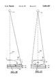
- FIG. 10 is a schematic side elevation diagram showing the radiation focal source of the X-ray tube delivering radiation to the patient's compressed breast beyond which is an air grid of the present invention and the photographic plate or image receiver.
- FIG. 11 is a corresponding front elevation diagram corresponding to FIG. 10.
- FIG. 12 is a block diagram of a first fabrication method employed to produce focused air cross grids of the present invention incorporating numerous photo-etched and laminated metal layers, bonded by adhesive.
- FIG. 13 is an enlarged end elevation view of a layer already photo-etched to produce air passages therethrough between crossed partitions, which is being lifted edgewise from an adhesive dipping bath between a pair of air knives positioned to clear away any adhesive which might be extending into the air passage.
- FIG. 14 is a fragmentary front elevation view corresponding to FIG. 13 showing the same lamination being drawn upward from its adhesive dipping bath, ascending past one of the air knives shown in FIG. 13.
- FIG. 15 is a block diagram of a second fabrication method employed to produce air cross grids of this invention incorporating plated metal coatings.
- FIG. 1 illustrates a cellular air cross grid typical of the grids of the present invention with the partition walls defining the cells passing through the grid being shown with an exaggerated convergence angle between adjacent walls to emphasize the fact that the cells are focused, i.e. aligned with their central axes converging at a point corresponding to the focal source of the X-rays produced by an X-ray tube in a mammography X-ray unit for example.
- These air passages or cells are unobstructed by any transverse interleaved layers of plastic or metal, and no surface covering layers of protective sheet material are needed with the air cross grids of the present invention.
- these cross grids are formed of stacked layers of metallic foil sheet, preferably beryllium-copper alloy or brass. Aligned portions of each sheet are removed by chemical milling or photo- etching to create the open air cell portions of each sheet, separated only by the partition wall portions thereof formed in a cross grid pattern. These chemically milled metal layers are then bonded together in the stacked configurations illustrated in FIGS. 1 and 2 where the convergent focussing orientation of the radiation axes forming the center line of each air passage or cell are easily seen to be converging at a focal point above the cross grids shown in these figures.
- FIGS. 1, 2, 5 and 14 are intended to illustrate the very large volume of air cells extending entirely through the cross grids of the present invention, as contrasted with the very thin partition walls between the air cells formed by the portion of these metal sheets remaining after the photo etching process is completed on each sheet.
- FIGS. 1, 2 and 5 it will be seen that the stack of eight sheets 21, 22, 23, 24, 26, 27, 28 and 29 are assembled and laminated together to define the large plurality of open air cell passages 31.
- These passages 31 all pass through the entire depth of the assembled laminated multi-layer grid assembly 32, and each air cell passage 31 may be considered to have a central axis 33 defining the direction it extends through the cross grid assembly 32.
- these axes 33 for adjacent cells 31 preferably converge at a focal point 52 corresponding to the source of the X-rays delivered through this grid 32.
- the partition walls defining and separating the adjacent air cells 31 are formed of individual partition segments 34 which are the only part of the metal foil sheet remaining after the chemical milling operation has removed the air cell portions thereof, aligned to create the through air cell passageways 31. These partition segments 34 are thus aligned with each other in successive sheets of the laminated assembly, as shown in FIGS. 1 and 2, to create partitions or sidewalls 36 shown at the right hand sides of FIGS. 1 and 2.
- the width of these partition segments 34 forming the sidewalls 36 measured in the plane of each metal sheet lamination is preferably between 0.0010 inches and 0.0020 inches, and in a preferred embodiment a partition width or wall thickness of 0.0012 ⁇ 0.00015 inches.
- the resulting grid structure 32 is a sturdy and highly useful implement in the mammography field, and provides the desired absorption of scattered secondary radiation entering the air cell passages 31 at a considerable angle from the axes 33.
- this cellular air grid is unusually well adapted to perform its scatter-reducing function while transmitting substantially all of the desired primary radiation without attenuation, significantly improving mammogram contrast and image quality at comparable radiation dosages.
- the beryllium-copper foil sheet material employed to form the laminations of 21, 22, 23 etc. is referably about 0.004 inches thick, and is preferably formed of a layer of beryllium-copper alloy known as Alloy No. 190, having a temper specified as "XHMS", sold by Brush Wellman of Fairfield, N.J.
- the air cell openings formed by photo-etching between the partition segments 34 in each lamination may be from 0.010 inches to 0.030 inches in internal width. Center to center distances between the center lines of the partition segments 34 forming the walls defining each air cell, have been selected as 0.017 inches in a preferred embodiment of the cellular air grids of the present invention illustrated in the figures, as shown in FIG. 5, where the thickness of the partition walls 34 is shown to be 0.0012 inches, falling within the range of 0.0010 inches to 0.0020 inches in useful embodiments of the device. With these dimensions as illustrated in FIG. 5, the very large volume of the overall assembly 32 occupied by air cell passages 31 is evident, as compared to the very small volume of the overall assembly 32 occupied by the partition walls 36.
- the partition walls occupy only about 14% of the total surface area of this air cross grid 32, leaving 86% of the total cross-sectional area available to receive and transmit the desired information-bearing primary radiation directly to the imaging unit, the X-ray film or digital imaging device.
- a cross grid 32 having these dimensions actually achieves transmission of about 82% of the desired primary radiation, while substantially blocking scattered secondary radiation. This effectiveness is considerably greater than has ever been achieved by any other form of commercially available fixed or moving grid. While a total number of eight laminations are illustrated in the figures, as many as 18 or 20 or more laminations may be employed if desired. To simplify the fabrication process, the minimum number of laminations required to achieve the desired scatter reduction is customarily employed.
- the bonding of the sheet metal foil layers 21, 22, 23 etc. together to form the laminated assembly 32 may be achieved by brazing, soldering, diffusion bonding or adhesive bonding techniques. It has been found that adhesive bonding with 3M adhesive coatings produced by Minnesota Mining and Manufacturing Company ("3M”) have produced highly effective air cross grid assemblies 32, using the techniques hereinafter described for the fabrication assembly methods. These methods apply a thin coating of epoxy adhesive 37 to the surfaces of the partition segments 34 and particularly to those portions of the surface planes of the metal foil sheets which are juxtaposed in abutting contact as the chemically milled layers are laminated together. These production methods also eliminate almost all excess adhesive which might otherwise project into air passages 31, and might reduce the size of these air cell passages.
- 3M adhesive coatings produced by Minnesota Mining and Manufacturing Company
- An alternate fabrication method employs a thin plated coating of lead, lead-tin or other metal on the partition segments, which are stacked in accurate registration, clamped together under pressure, and heated to melt and fuse the plated coatings, bonding all of the stacked layers to form an integral laminated air grid.
- FIG. 5 showing an enlarged portion of the air cross grid 32 of the present invention, the air cell passages 31 and the partition walls 36 defining them are clearly illustrated.
- a circle 38 identifying a corner junction where perpendicular partition walls 36 join, and the photoresist pattern forming such junctions is illustrated in enlarged detail in FIG. 6.
- a possible problem sometimes encountered with the chemical milling or photo etching process is also illustrated by a dashed line 39 showing a corner fillet which may be formed at the junction 40 where the partition walls 36 join.
- Such a fillet 39 is undesirable because it reduces the overall area of the air grid cell 31 available for passing primary radiation, and it increases the cross sectional area of the junction regions, which are carefully dimensioned for optimum elimination of image shadows by grid movement during each X-ray exposure.
- the mask or masking tool employed in the chemical milling or photo-etching process is preferably provided with square cornered diagonal projections 41, reducing the effective cross-sectional area of the junction regions to the desired value.
- Diagonal projections 41 protrude into the junction area 40 from each of the four air cell passage regions 31 surrounding junction 40, all as illustrated in FIG. 7. Projection 41 has the effect of ensuring that any "filleting" left behind by the chemical milling process will be concentrated at the inside corners of the resulting diagonal groove, leaving substantially the entire square area of each air cell passage region 31 open directly to its corner at each junction 40, and reducing the junction area to the desired value.
- FIGS. 8 and 9 show the general appearance of the cellular air cross grids of the present invention with the outer edges mounted in protective frames 42.
- the pattern of partitions 34 and cells 31 is aligned with the rectangular edges of the frame 42.
- the focal point F is normally placed in the center of the grid panel, and not near one edge.
- the air cell passages 31 close to this point F will have their cell axes 33 substantially parallel to the perpendicular axis of the cell directly at point F.
- the cell axes 33 of such cells will be seen to be progressively more slanting, to converge at the same focal point 52 directly above point F when the cross grid is in use. This successively greater converging slant of the axes 33 is illustrated in FIG. 2, somewhat exaggerated for clarity.
- FIG. 9 shows a diagonal orientation of the partition walls 36 and the air cell passages 31 when the assembly 32 is mounted in a frame 42 for use as a moving or Bucky grid.
- Arrow 43 at the left hand side of FIG. 5 shows the direction of movement of a particular junction 40 to its new position 40A during the course of the translation movement.
- Arrow 44 shows the translation of a central axis 33 of one of the air cell passages 31 to its new position 33A following translation movement.
- FIG. 5 are examples of instantaneous intermediate positions in which the cross grid structure will be found at various times during its continuous diagonal translation movement during the entire X-ray exposure period. This is desired to avoid even the shadow image which might be created if the partition walls came to a stop at any time during the exposure either to reverse direction or to continue after an increment of movement. Continuous movement during exposure thus produces the most effective elimination of all such shadow images from the partition walls of a moving grid.
- the direction of movement 44 for such a moving or Bucky grid as that shown in FIG. 9 is indicated by arrow 44 in the schematic diagrams of FIGS. 10 and 11.
- FIG. 10 is a side view of a mammography X-ray procedure showing the patient's breast 46 held stable in the mammography device between an underlying breast tray 47 and an overlying clamping plate 48 gently moved into position to deter any unnecessary movement during the exposure and to minimize the thickness of breast tissue for best X-ray imaging.
- the imaging unit beneath the breast tray 47 includes the moving Bucky grid 50 of the kind illustrated in FIG. 9 with diagonal orientation of the cross grid pattern, overlying a film cassette 49 incorporating the X-ray film 51 encased inside cassette 49.
- Point F shown at the midpoint of the grid's lower edge in FIG. 9, is indicated at the left-hand edge of grid 50 in FIG. 10, close to the patient and directly beneath the focal source point 52 which is shown with a source to image distance or SID represented as a dash line extending from X-ray source 52 through the patient's breast 46 and through the Bucky grid 50 at point F into the film cassette 49 to expose the film 51.
- SID dash line is perpendicular to the Bucky grid 50 and to the film 51 as indicated by the diagram of FIG. 10.
- the direction of movement 44 of Bucky grid 50 is indicated by an X shown midway across the shorter dimension of Bucky grid 50 from the patient to the outer free edge of the Bucky grid, thus indicating that the grid moves in the direction parallel to the patient's sternum and parallel to the focal point edge of grid 50, from right to left for example.
- the front elevation diagram of FIG. 11 further indicates the normal positioning of the air cross grid 50 of the present invention, when used as moving or Bucky grid, moving from the patient's right to the patient's left in the direction shown by the arrow 44 during the X-ray exposure.
- the point F is positioned under the middle of the breast at the midpoint of the translation movement of the Bucky grid during the exposure period.
- the SID dash line extending from X-ray source 52 directly perpendicular to film cassette 49 containing film 51 identifies the radiation travelling directly along this perpendicular radiation axis as it passes through Bucky grid 50 at point F and travels toward the film 51 in cassette 49.
- the actual dimensions of a preferred version of the movable Bucky grid 50 are 18 centimeters in width and 26 centimeters in length for an 18 cm ⁇ 24 cm cassette, or 24 cm ⁇ 32 cm for a 24 cm ⁇ 30 cm cassette, and the SID distance from the X-ray film image to the X-ray source is 63 centimeters.
- the grids of this invention are preferably moved at a precise angle A (FIG. 9) and distance during the X-ray exposure so that an integral number of grid lines in each of the two perpendicular partition directions will pass each point of the image.
- the ratio of the two directions is preferably set so that there is no repeating trace pattern of the intersections of grid partitions until at least 9 grid lines have passed a specific image point.
- Cross grid partitions absorb scattered X-rays slanting in many directions.
- the X-ray intensity variations produced by moving the grid should be reduced below about 1%.
- the usual technique with fine linear (non-cross) grids is to have the grid move with uniform velocity during the exposure. If the motion is fast enough so that about 100 lines cross each spot, the absorption difference due to the start and end positions during the exposure will be less than one line crossing or 1%.
- the patterns are coarser, and the grid must be angled so that the motion translates both of the sets of perpendicular lines. Because the grid intersections represent a single line width, these areas will tend to be overexposed as compared to the in-between or open areas which are traversed by the two sets of cross lines. By choosing the grid translation angle so that as many intersection traces as possible are adjacent rather than coincident, the intersection traces can cover the entire space and become invisible.
- a suitable linear transverse motion would move the grid lines exactly one open space distance with uniform velocity during the exposure. Then each portion of the image will be obscured for exactly the same interval, and there will be no line image.
- the grid For the cross lines to behave similarly the grid must be angled such that an integral number of lines will be moved in both sets. Thus angles A giving line motion ratios of 1:1, 1:2, 5:4 etc. would be suitable. The more lines that are moved, the more tolerance allowed in the position, since any fixed error in the mechanism will be a smaller fraction of the total motion.
- the maximum travel is limited by both the focus shift and the constraints of the Bucky stage. A practical limit for travel is about 2.5 cm. With a 1 mm grid spacing and a 45 degree angle A, the motion can cover about 18 lines.
- the angle A of the grid determines the repeat pattern of the image-traces of intersections and to cover the space as uniformly as possible the number of lines to a repeat should be large. Ratios such as 9:1, 9:2: - - - 9:8 appear to give adequate coverage. A ratio or trigonometric "tangent" of about 16:11 (34.6°) defines a suitable angle A (FIG. 9). Two patterns then are 16 lines by 11 lines.
- the air cross grid 30 and the moving Bucky grid 50 shown in FIGS. 8 and 9, both incorporating the cross grid structure illustrated in FIGS. 1, 2 and 5, may be fabricated using the choice of bonding techniques previously mentioned for joining the stacked layers of chemically milled beryllium copper foil sheet in the desired registration, with the openings therein forming the air cell passages 31 illustrated in the figures. These techniques include brazing, soldering, diffusion bonding or adhesive bonding.
- each of the multiple layers of metallic foil sheet material is first chemically milled to remove the air cell passage portions 31, leaving only the partition segments 34 in place.
- a mask tool is employed and for each metal foil layer a pair of mask tools or web negatives are applied to the opposite faces of the foil sheet material, which has been coated by a photoresist on each of its surfaces.
- the photoresist application step is identified as step 53 in FIG. 12 and the application of the aligned mask tools or web negatives positioned in registration on opposite surfaces of the foil sheet is identified as step 54.
- partition segments 34 photo-etched in planes perpendicular to the foil surface.
- a mask tool sized for the slightly wider "focused” spacing of the next adjacent foil sheet will produce converging "focused” partition segments 35 (FIGS. 4 and 4A).
- the sandwich of two web negative mask tools aligned in registration flanking both faces of the sheet of the foil sheet blank is next exposed to ultraviolet light projected on both surfaces through the web negatives to expose the photoresist coatings to ultraviolet radiation in step 56.
- step 57 The web negatives are then removed and a developer solution is applied in step 57.
- the foil sheet blanks are next etched in step 58 to perform the "chemical milling" removal of the air space sections 31 forming the air cell passages, leaving only the cross grid partition segments 34 as illustrated in FIG. 14.
- This cross grid structure formed only of partition segments 34 is referred to as a fine web structure, and after all remaining photoresist is removed, this web is next dipped in liquid adhesive in the step 59.
- the liquid adhesive bath 61 is illustrated in FIGS. 13 and 14, where the web is being removed edgewise in an upward movement illustrated by the arrow 62 in FIG. 13.
- the upward movement of the web identified as metal sheet 21 in FIGS. 13 and 14 passes it upward between a pair of air knives 63, delivering thin wide fast moving curtains 64 of compressed air or nitrogen through an elongated narrow slot 66 formed in each of the air knives 63.
- These wide flat streams of compressed gas are directed diagonally at the two faces of the web structure of sheet 21, as indicated in FIG.
- This air knife adhesive removal step is identified by the number 68 in FIG. 12 and the assembly of the successive layers 21, 22, 23 etc. aligned by registration indicia on the edge of each layer, to form the laminated assembled air grid 32 illustrated in FIGS. 1 and 2, is identified as step 69 in FIG. 12.
- the preferred bonding adhesive used in these fabrication methods is 3M SCOTCH-GRIP® plastic adhesive Model 1099L, diluted with acetone in accordance with the manufacturer's recommendations to decrease its viscosity. This adhesive is air curable, requiring no heat to be supplied during curing.
- Another suitable adhesive is Beacon Chemical Company's MAGNA-TAC® Model E645 two part epoxy adhesive, diluted with a 50-50 mixture of acetone and isopropyl alcohol for reduced viscosity.
- the curing of the adhesive between the layers identified as step 71 in FIG. 12 is performed while these layers are maintained in precise registration in the alignment illustrated in FIGS. 1, 2 and 3 to create the desired convergence of the axes 33 and provide a focused cross grid with all of these axes 33 converging at the X-ray source 52 illustrated in FIGS. 10 and 11.
- partition segments result which are perpendicular to the parallel faces of each of the foil sheets as illustrated in FIGS. 1 and 2, and the slight convergence of their axes 33 produces a slight stepwise misalignment between the successive partition segments 34 in each of the layers as illustrated in FIG. 3, where it is shown that adhesive 37 is effective only in the overlapping juxtaposed end portions of such stepwise aligned partition segments 34.
- the resulting slanted partition segments 35 may be produced by the etching operation, with a slight converging slant parallel to the desired cell axes 33, as indicated in FIG. 4.
- This convergent slant partition segment etching operation thus minimizes the stepwise alignment of the successive partition segments making up each partition wall 36, avoiding any risk of total misalignment at the grid corners most remote from focal point F, and thus allows the adhesive 37 to be bonded to all or a larger portion of the facing abutting surfaces of the partition segments 34, all as shown in FIG. 4.
- the grids of this invention also avoid the disadvantage of interleaved "transparent" material designed to transmit X-rays through the cell passages. Most such materials are incapable of transmitting X-rays without absorbing some portion of the radiation. In this way, the radiation dose to which the patient is exposed can be held to the absolute minimum while achieving high quality mammograms with good detail, excellent contrast and no undesired shadow images of crossed partitions.
- outer dustcover sheets or films of polycarbonate may be applied to protect the exposed surfaces of these air grids.
- a plated coating of lead or a lead-tin mixture on each photo-etched foil sheet web can be employed, if desired, to enhance the absorption of secondary scattered radiation, and aligned plated partition segments 35 are shown in FIGS. 4 and 4A, and fabricated using the method shown in the flow sheet diagram of FIG. 15.
- plated partition segments 35 are formed of beryllium-copper foil, chemically machined by photo-etching as described above in the converging, slanted segment orientation.
- a coating 72 of intermediate metal, such as copper, is applied by plating to the web's surface, in step 73 (FIG. 15).
- An outer bonding metal coating 74 of lead or lead-tin mixture is then plated over coating 72 in step 76.
- the plated web structures after being dipped in a liquid flux, are precisely aligned in step 77 using mechanical or optical registration indicia or both marked on each foil sheet, and then clamped in an assembled stack and heated between clamping plates in step 78, in a hydrogen atmosphere in a hydrogen pusher furnace, to a temperature just sufficient to melt and fuse the bonding metal plating layers 74 at the bond zones 79 where the slanted "convergent" partition segments 35 of successive adjacent foil sheets are engaged in coincident alignment (FIGS. 4 and 4A).
- these plated air cross grids are sturdy, rigid panels, well adapted for use in absorbing secondary scattered radiation in mammography procedures.
Abstract
Description
Claims (14)
Priority Applications (4)
| Application Number | Priority Date | Filing Date | Title |
|---|---|---|---|
| US08/438,172 US5606589A (en) | 1995-05-09 | 1995-05-09 | Air cross grids for mammography and methods for their manufacture and use |
| US08/759,798 US5814235A (en) | 1995-05-09 | 1996-12-03 | Air cross grids for mammography and methods for their manufacture and use |
| US08/761,538 US5729585A (en) | 1995-05-09 | 1996-12-06 | Air cross grids for mammography and methods for their manufacture and use |
| US09/021,655 US6075840A (en) | 1995-05-09 | 1998-02-10 | Air cross grids for X-ray imaging |
Applications Claiming Priority (1)
| Application Number | Priority Date | Filing Date | Title |
|---|---|---|---|
| US08/438,172 US5606589A (en) | 1995-05-09 | 1995-05-09 | Air cross grids for mammography and methods for their manufacture and use |
Related Child Applications (2)
| Application Number | Title | Priority Date | Filing Date |
|---|---|---|---|
| US08/759,798 Division US5814235A (en) | 1995-05-09 | 1996-12-03 | Air cross grids for mammography and methods for their manufacture and use |
| US08/761,538 Division US5729585A (en) | 1995-05-09 | 1996-12-06 | Air cross grids for mammography and methods for their manufacture and use |
Publications (1)
| Publication Number | Publication Date |
|---|---|
| US5606589A true US5606589A (en) | 1997-02-25 |
Family
ID=23739543
Family Applications (4)
| Application Number | Title | Priority Date | Filing Date |
|---|---|---|---|
| US08/438,172 Expired - Lifetime US5606589A (en) | 1995-05-09 | 1995-05-09 | Air cross grids for mammography and methods for their manufacture and use |
| US08/759,798 Expired - Lifetime US5814235A (en) | 1995-05-09 | 1996-12-03 | Air cross grids for mammography and methods for their manufacture and use |
| US08/761,538 Expired - Lifetime US5729585A (en) | 1995-05-09 | 1996-12-06 | Air cross grids for mammography and methods for their manufacture and use |
| US09/021,655 Expired - Lifetime US6075840A (en) | 1995-05-09 | 1998-02-10 | Air cross grids for X-ray imaging |
Family Applications After (3)
| Application Number | Title | Priority Date | Filing Date |
|---|---|---|---|
| US08/759,798 Expired - Lifetime US5814235A (en) | 1995-05-09 | 1996-12-03 | Air cross grids for mammography and methods for their manufacture and use |
| US08/761,538 Expired - Lifetime US5729585A (en) | 1995-05-09 | 1996-12-06 | Air cross grids for mammography and methods for their manufacture and use |
| US09/021,655 Expired - Lifetime US6075840A (en) | 1995-05-09 | 1998-02-10 | Air cross grids for X-ray imaging |
Country Status (1)
| Country | Link |
|---|---|
| US (4) | US5606589A (en) |
Cited By (53)
| Publication number | Priority date | Publication date | Assignee | Title |
|---|---|---|---|---|
| US5721761A (en) * | 1996-09-20 | 1998-02-24 | Ferlic; Daniel J. | Radiographic grid with reduced lamellae density artifacts |
| US6031893A (en) * | 1997-06-24 | 2000-02-29 | Siemens Aktiengesellschaft | Stray radiation grid |
| EP0990239A1 (en) * | 1997-06-19 | 2000-04-05 | Creatv Microtech, Inc. | A method and apparatus for making large area two-dimensional grids |
| US6055296A (en) * | 1996-09-20 | 2000-04-25 | Ferlic; Daniel J. | Radiographic grid with reduced lamellae density artifacts |
| WO2000026922A1 (en) * | 1998-10-29 | 2000-05-11 | Direct Radiography Corp. | Anti scatter radiation grid for a detector having discreet sensing elements |
| US6181773B1 (en) | 1999-03-08 | 2001-01-30 | Direct Radiography Corp. | Single-stroke radiation anti-scatter device for x-ray exposure window |
| US6272207B1 (en) | 1999-02-18 | 2001-08-07 | Creatv Microtech, Inc. | Method and apparatus for obtaining high-resolution digital X-ray and gamma ray images |
| EP1182671A2 (en) | 2000-08-24 | 2002-02-27 | General Electric Company | X-ray anti-scatter grid |
| US20020037070A1 (en) * | 1999-12-13 | 2002-03-28 | Cha-Mei Tang | Two-dimensional, anti-scatter grid and collimator designs, and its motion, fabrication and assembly |
| US6366643B1 (en) | 1998-10-29 | 2002-04-02 | Direct Radiography Corp. | Anti scatter radiation grid for a detector having discreet sensing elements |
| US6438210B1 (en) | 2000-03-28 | 2002-08-20 | General Electric Company | Anti-scatter grid, method, and apparatus for forming same |
| US20030026386A1 (en) * | 2001-02-01 | 2003-02-06 | Cha-Mei Tang | Anti-scatter grids and collimator designs, and their motion, fabrication and assembly |
| US6529582B2 (en) * | 2000-02-01 | 2003-03-04 | The Johns Hopkins University | Focused X-ray scatter reduction grid |
| US20030065401A1 (en) * | 2001-01-25 | 2003-04-03 | Mark Amrich | Textured surface having undercut micro recesses in a surface |
| US20030081731A1 (en) * | 2001-10-17 | 2003-05-01 | Henri Souchay | Antiscattering grid and a method of manufacturing such a grid |
| US20030128812A1 (en) * | 2001-12-17 | 2003-07-10 | Michael Appleby | Devices, methods, and systems involving cast collimators |
| US20030128813A1 (en) * | 2001-12-17 | 2003-07-10 | Michael Appleby | Devices, methods, and systems involving cast computed tomography collimators |
| US6599322B1 (en) | 2001-01-25 | 2003-07-29 | Tecomet, Inc. | Method for producing undercut micro recesses in a surface, a surgical implant made thereby, and method for fixing an implant to bone |
| US6620332B2 (en) | 2001-01-25 | 2003-09-16 | Tecomet, Inc. | Method for making a mesh-and-plate surgical implant |
| US20030235272A1 (en) * | 2002-06-05 | 2003-12-25 | Michael Appleby | Devices, methods, and systems involving castings |
| KR100414046B1 (en) * | 2001-02-23 | 2004-01-13 | 노정희 | Pb ARRAYMENT STRUCTURE of X-ray Grid. |
| US6690767B2 (en) | 1998-10-29 | 2004-02-10 | Direct Radiography Corp. | Prototile motif for anti-scatter grids |
| US20040052332A1 (en) * | 2002-09-13 | 2004-03-18 | Banchieri Andrew J. | X-ray collimator and a method of making an x-ray collimator |
| US20040131158A1 (en) * | 2002-09-06 | 2004-07-08 | Martin Hoheisel | Method for producing and applying an antiscatter grid or collimator to an x-ray or gamma detector |
| US20040156478A1 (en) * | 2001-06-05 | 2004-08-12 | Appleby Michael P | Methods for manufacturing three-dimensional devices and devices created thereby |
| US6807252B1 (en) | 2001-10-24 | 2004-10-19 | Analogic Corporation | Method for making X-ray anti-scatter grid |
| US20040228447A1 (en) * | 2003-05-13 | 2004-11-18 | Dobbs John M. | Method for making X-ray anti-scatter grid |
| US20050082351A1 (en) * | 2003-10-17 | 2005-04-21 | Jmp Industries, Inc., An Ohio Corporation | Micro-reactor fabrication |
| US20050084072A1 (en) * | 2003-10-17 | 2005-04-21 | Jmp Industries, Inc., An Ohio Corporation | Collimator fabrication |
| US20050281701A1 (en) * | 2002-12-09 | 2005-12-22 | Lynch Robert F | Densified particulate/binder composites |
| US20060158755A1 (en) * | 2005-01-14 | 2006-07-20 | Kazuhisa Matsuda | X-ray focusing device |
| US20070041505A1 (en) * | 2005-08-19 | 2007-02-22 | General Electric Company | Simplified way to manufacture a low cost cast type collimator assembly |
| US20080230706A1 (en) * | 2004-04-06 | 2008-09-25 | Koninklijke Philips Electronics N.V. | Modular Device For the Detection and/or Transmission of Radiation |
| US20090016494A1 (en) * | 2006-02-02 | 2009-01-15 | Koninklijke Philips Electronics N.V. | Anti-scatter device, method and system |
| US7638732B1 (en) | 2002-10-24 | 2009-12-29 | Analogic Corporation | Apparatus and method for making X-ray anti-scatter grid |
| US7785098B1 (en) | 2001-06-05 | 2010-08-31 | Mikro Systems, Inc. | Systems for large area micro mechanical systems |
| US20110013743A1 (en) * | 2008-03-13 | 2011-01-20 | Canon Kabushiki Kaisha | Phase grating used for x-ray phase imaging, imaging apparatus for x-ray phase contrast image using phase grating, and x-ray computed tomography system |
| US7922923B2 (en) | 2001-02-01 | 2011-04-12 | Creatv Microtech, Inc. | Anti-scatter grid and collimator designs, and their motion, fabrication and assembly |
| US20110164727A1 (en) * | 2008-08-11 | 2011-07-07 | Hiromichi Tonami | Radiation grid and radiographic apparatus provided with the same |
| US20110189440A1 (en) * | 2008-09-26 | 2011-08-04 | Mikro Systems, Inc. | Systems, Devices, and/or Methods for Manufacturing Castings |
| US20120163553A1 (en) * | 2010-12-27 | 2012-06-28 | Analogic Corporation | Three-dimensional metal printing |
| JPWO2012036160A1 (en) * | 2010-09-14 | 2014-02-03 | 株式会社東芝 | Mo collimator and X-ray detector, X-ray inspection apparatus and CT apparatus using the same |
| US20140119508A1 (en) * | 2012-10-31 | 2014-05-01 | Samsung Electronics Co., Ltd. | Collimator module, radiation detector having collimator module, radiological imaging apparatus having collimator module, and control method of radiological imaging apparatus |
| US8813824B2 (en) | 2011-12-06 | 2014-08-26 | Mikro Systems, Inc. | Systems, devices, and/or methods for producing holes |
| US20160078972A1 (en) * | 2014-09-15 | 2016-03-17 | Siemens Aktiengesellschaft | Method for manufacturing a collimator module and method for manufacturing a collimator bridge as well as collimator module, collimator bridge, collimator and tomography device |
| US20160247590A1 (en) * | 2015-02-24 | 2016-08-25 | Carestream Health, Inc. | Flexible antiscatter grid |
| US20180168522A1 (en) * | 2016-12-16 | 2018-06-21 | General Electric Company | Collimator structure for an imaging system |
| US10638994B2 (en) | 2002-11-27 | 2020-05-05 | Hologic, Inc. | X-ray mammography with tomosynthesis |
| US11123029B2 (en) * | 2018-06-20 | 2021-09-21 | Siemens Healthcare Gmbh | Method for producing a grid-like beam collimator, grid-like beam collimator comprising a grid structure having metal particles and a cured stiffening material, radiation detector, and medical imaging device |
| US11139088B2 (en) | 2019-06-12 | 2021-10-05 | alephFS—Systems for Imaging | Grid for X-ray imaging |
| US11471118B2 (en) | 2020-03-27 | 2022-10-18 | Hologic, Inc. | System and method for tracking x-ray tube focal spot position |
| US11510306B2 (en) | 2019-12-05 | 2022-11-22 | Hologic, Inc. | Systems and methods for improved x-ray tube life |
| DE102022210085A1 (en) | 2022-09-23 | 2024-03-28 | Siemens Healthcare Gmbh | Method for producing a component for a medical imaging device |
Families Citing this family (28)
| Publication number | Priority date | Publication date | Assignee | Title |
|---|---|---|---|---|
| US6185278B1 (en) | 1999-06-24 | 2001-02-06 | Thermo Electron Corp. | Focused radiation collimator |
| EP1107260B1 (en) * | 1999-11-30 | 2008-10-15 | Philips Intellectual Property & Standards GmbH | X-ray absorbing grid |
| FR2825611B1 (en) * | 2001-06-06 | 2004-03-12 | Ge Med Sys Global Tech Co Llc | MAMMOGRAPHY APPARATUS AND BREAST SUPPORT FOR SUCH AN APPARATUS |
| DE10147947C1 (en) * | 2001-09-28 | 2003-04-24 | Siemens Ag | Process for producing an anti-scatter grid or collimator |
| FR2855276B1 (en) * | 2003-05-22 | 2005-07-15 | Ge Med Sys Global Tech Co Llc | ANTI-DIFFUSING GRID HAVING AN IMPROVED MECHANICAL STRENGTH |
| EP1680789B1 (en) * | 2003-09-12 | 2011-11-16 | Philips Intellectual Property & Standards GmbH | Arrangement for collimating electromagnetic radiation |
| US8066955B2 (en) * | 2003-10-17 | 2011-11-29 | James M. Pinchot | Processing apparatus fabrication |
| DE102004027158B4 (en) * | 2004-06-03 | 2010-07-15 | Siemens Ag | Method for producing a scattered radiation grid or collimator of absorbent material |
| DE102005044650B4 (en) * | 2005-09-19 | 2008-07-10 | Siemens Ag | Scattering grid with a cell-like structure of radiation channels and method for producing such a scattered radiation grid |
| CN101484949B (en) * | 2006-07-07 | 2013-08-21 | 皇家飞利浦电子股份有限公司 | Grid for selective transmission of electromagnetic radiation |
| US20080165922A1 (en) * | 2007-01-09 | 2008-07-10 | Brian David Yanoff | Laminated ct collimator and method of making same |
| US7869573B2 (en) * | 2007-12-27 | 2011-01-11 | Morpho Detection, Inc. | Collimator and method for fabricating the same |
| JP5047826B2 (en) * | 2008-01-31 | 2012-10-10 | ジーイー・メディカル・システムズ・グローバル・テクノロジー・カンパニー・エルエルシー | Collimators, collimator stacks, and multi-modality systems |
| JP2009195512A (en) * | 2008-02-22 | 2009-09-03 | Fujifilm Corp | Radiation image processing apparatus |
| DE102008013414B4 (en) * | 2008-03-10 | 2015-06-03 | Siemens Aktiengesellschaft | A scattered radiation collimator element, a scattered radiation collimator, a radiation detector unit and a method for producing a scattered radiation absorber element |
| JP4715974B2 (en) * | 2008-07-22 | 2011-07-06 | 株式会社島津製作所 | Method for producing scattered radiation removal grid |
| WO2010044008A1 (en) * | 2008-10-13 | 2010-04-22 | Philips Intellectual Property & Standards Gmbh | Grid and method of manufacturing a grid for selective transmission of electromagnetic radiation, particularly x-ray radiation for mammography applications |
| KR101503806B1 (en) * | 2008-11-27 | 2015-03-19 | 엘지이노텍 주식회사 | Manufacturing Method of Grid In Gas Typr Detector For Detecting X-Ray Image And Detecting System |
| WO2010077626A1 (en) * | 2008-12-09 | 2010-07-08 | Mayo Foundation For Medical Education And Research | Collimator for low-dose molecular breast imaging |
| US8917813B2 (en) | 2010-02-24 | 2014-12-23 | Accuray Incorporated | Gantry image guided radiotherapy system and related treatment delivery methods |
| US9687200B2 (en) | 2010-06-08 | 2017-06-27 | Accuray Incorporated | Radiation treatment delivery system with translatable ring gantry |
| US8804901B2 (en) | 2010-06-08 | 2014-08-12 | Accuray Incorporated | Imaging methods for image-guided radiation treatment |
| WO2012057371A1 (en) * | 2010-10-26 | 2012-05-03 | 주식회사 아임 | X-ray grid and preparation method thereof |
| CN103200874B (en) * | 2010-11-08 | 2015-11-25 | 皇家飞利浦电子股份有限公司 | For the grating of phase contrast imaging |
| US8536547B2 (en) | 2011-01-20 | 2013-09-17 | Accuray Incorporated | Ring gantry radiation treatment delivery system with dynamically controllable inward extension of treatment head |
| US9219178B2 (en) * | 2014-03-21 | 2015-12-22 | Kabushiki Kaisha Toshiba | Method to fabricate collimator structures on a direct conversion semiconductor X-ray detector |
| CN106226916A (en) * | 2016-07-26 | 2016-12-14 | 中国科学院高能物理研究所 | Optics collimator and processing method thereof |
| GB2572217A (en) * | 2018-03-23 | 2019-09-25 | Rolls Royce Plc | X-ray imaging systems and methods, and methods of manufacture of Collimators for use therein |
Citations (27)
| Publication number | Priority date | Publication date | Assignee | Title |
|---|---|---|---|---|
| US1164987A (en) * | 1914-02-03 | 1915-12-21 | Siemens Ag | Method of and apparatus for projecting röntgen images. |
| US1208474A (en) * | 1915-10-12 | 1916-12-12 | Eugene W Caldwell | X-ray screening apparatus. |
| US2133385A (en) * | 1937-05-08 | 1938-10-18 | Antony P Freeman | X-ray grid and method of making same |
| US2605427A (en) * | 1948-11-25 | 1952-07-29 | Delhumeau Roger Andre | Diffusion-preventing device for x-rays |
| US2824970A (en) * | 1952-04-04 | 1958-02-25 | Ledin Sven Harald | Secondary diaphragms for x-ray radiography |
| US3665186A (en) * | 1964-12-15 | 1972-05-23 | Fuji Photo Film Co Ltd | Half tone radiography method and apparatus |
| US3717764A (en) * | 1969-03-07 | 1973-02-20 | Fuji Photo Film Co Ltd | Intensifying screen for radiograph use |
| SU441019A1 (en) * | 1972-12-13 | 1974-08-30 | X-ray raster | |
| US4288697A (en) * | 1979-05-03 | 1981-09-08 | Albert Richard D | Laminate radiation collimator |
| US4340818A (en) * | 1980-05-14 | 1982-07-20 | The Board Of Trustees Of The University Of Alabama | Scanning grid apparatus for suppressing scatter in radiographic imaging |
| US4414679A (en) * | 1982-03-01 | 1983-11-08 | North American Philips Corporation | X-Ray sensitive electrophoretic imagers |
| US4465540A (en) * | 1979-05-03 | 1984-08-14 | Albert Richard D | Method of manufacture of laminate radiation collimator |
| US4688242A (en) * | 1985-04-30 | 1987-08-18 | Kabushiki Kaisha Toshiba | X-ray imaging system |
| US4951305A (en) * | 1989-05-30 | 1990-08-21 | Eastman Kodak Company | X-ray grid for medical radiography and method of making and using same |
| US4969176A (en) * | 1988-03-18 | 1990-11-06 | U.S. Philips Corporation | X-ray examination apparatus having a stray radiation grid with anti-vignetting effect |
| US5062129A (en) * | 1987-05-12 | 1991-10-29 | B.V. Optische Industrie "De Oude Delft" | Device for slit radiography with image equalization |
| US5099134A (en) * | 1988-05-27 | 1992-03-24 | Kabushiki Kaisha Toshiba | Collimator and a method of producing a collimator for a scintillator |
| US5198680A (en) * | 1991-03-27 | 1993-03-30 | Kabushiki Kaisha Toshiba | High precision single focus collimator and method for manufacturing high precision single focus collimator |
| US5231654A (en) * | 1991-12-06 | 1993-07-27 | General Electric Company | Radiation imager collimator |
| US5231655A (en) * | 1991-12-06 | 1993-07-27 | General Electric Company | X-ray collimator |
| US5239568A (en) * | 1990-10-29 | 1993-08-24 | Scinticor Incorporated | Radiation collimator system |
| US5263075A (en) * | 1992-01-13 | 1993-11-16 | Ion Track Instruments, Inc. | High angular resolution x-ray collimator |
| US5291539A (en) * | 1992-10-19 | 1994-03-01 | General Electric Company | Variable focussed X-ray grid |
| US5307394A (en) * | 1993-01-27 | 1994-04-26 | Oleg Sokolov | Device for producing X-ray images on objects composed of photo or X-ray sensitive materials |
| US5389473A (en) * | 1993-11-10 | 1995-02-14 | Sokolov; Oleg | Method of producing x-ray grids |
| US5418833A (en) * | 1993-04-23 | 1995-05-23 | The Regents Of The University Of California | High performance x-ray anti-scatter grid |
| US5455849A (en) * | 1994-09-01 | 1995-10-03 | Regents Of The University Of California | Air-core grid for scattered x-ray rejection |
Family Cites Families (5)
| Publication number | Priority date | Publication date | Assignee | Title |
|---|---|---|---|---|
| US2566998A (en) * | 1948-11-05 | 1951-09-04 | Charles E Bloom | Bucky grid and method of making same |
| US3909656A (en) * | 1974-05-02 | 1975-09-30 | Zenith Radio Corp | Layered, one-sided etched color selection electrode |
| ATA331285A (en) * | 1985-11-13 | 1988-11-15 | Ims Ionen Mikrofab Syst | METHOD FOR PRODUCING A TRANSMISSION MASK |
| US5268068A (en) * | 1992-12-08 | 1993-12-07 | International Business Machines Corporation | High aspect ratio molybdenum composite mask method |
| US5357554A (en) * | 1993-09-30 | 1994-10-18 | General Electric Company | Apparatus and method for reducing X-ray grid line artifacts |
-
1995
- 1995-05-09 US US08/438,172 patent/US5606589A/en not_active Expired - Lifetime
-
1996
- 1996-12-03 US US08/759,798 patent/US5814235A/en not_active Expired - Lifetime
- 1996-12-06 US US08/761,538 patent/US5729585A/en not_active Expired - Lifetime
-
1998
- 1998-02-10 US US09/021,655 patent/US6075840A/en not_active Expired - Lifetime
Patent Citations (28)
| Publication number | Priority date | Publication date | Assignee | Title |
|---|---|---|---|---|
| US1164987A (en) * | 1914-02-03 | 1915-12-21 | Siemens Ag | Method of and apparatus for projecting röntgen images. |
| US1208474A (en) * | 1915-10-12 | 1916-12-12 | Eugene W Caldwell | X-ray screening apparatus. |
| US2133385A (en) * | 1937-05-08 | 1938-10-18 | Antony P Freeman | X-ray grid and method of making same |
| US2605427A (en) * | 1948-11-25 | 1952-07-29 | Delhumeau Roger Andre | Diffusion-preventing device for x-rays |
| US2824970A (en) * | 1952-04-04 | 1958-02-25 | Ledin Sven Harald | Secondary diaphragms for x-ray radiography |
| US3665186A (en) * | 1964-12-15 | 1972-05-23 | Fuji Photo Film Co Ltd | Half tone radiography method and apparatus |
| US3717764A (en) * | 1969-03-07 | 1973-02-20 | Fuji Photo Film Co Ltd | Intensifying screen for radiograph use |
| SU441019A1 (en) * | 1972-12-13 | 1974-08-30 | X-ray raster | |
| US4288697A (en) * | 1979-05-03 | 1981-09-08 | Albert Richard D | Laminate radiation collimator |
| US4465540A (en) * | 1979-05-03 | 1984-08-14 | Albert Richard D | Method of manufacture of laminate radiation collimator |
| US4340818A (en) * | 1980-05-14 | 1982-07-20 | The Board Of Trustees Of The University Of Alabama | Scanning grid apparatus for suppressing scatter in radiographic imaging |
| US4414679A (en) * | 1982-03-01 | 1983-11-08 | North American Philips Corporation | X-Ray sensitive electrophoretic imagers |
| US4688242A (en) * | 1985-04-30 | 1987-08-18 | Kabushiki Kaisha Toshiba | X-ray imaging system |
| US4837796A (en) * | 1985-04-30 | 1989-06-06 | Kabushiki Kaisha Toshiba | X-ray imaging system |
| US5062129A (en) * | 1987-05-12 | 1991-10-29 | B.V. Optische Industrie "De Oude Delft" | Device for slit radiography with image equalization |
| US4969176A (en) * | 1988-03-18 | 1990-11-06 | U.S. Philips Corporation | X-ray examination apparatus having a stray radiation grid with anti-vignetting effect |
| US5099134A (en) * | 1988-05-27 | 1992-03-24 | Kabushiki Kaisha Toshiba | Collimator and a method of producing a collimator for a scintillator |
| US4951305A (en) * | 1989-05-30 | 1990-08-21 | Eastman Kodak Company | X-ray grid for medical radiography and method of making and using same |
| US5239568A (en) * | 1990-10-29 | 1993-08-24 | Scinticor Incorporated | Radiation collimator system |
| US5198680A (en) * | 1991-03-27 | 1993-03-30 | Kabushiki Kaisha Toshiba | High precision single focus collimator and method for manufacturing high precision single focus collimator |
| US5231654A (en) * | 1991-12-06 | 1993-07-27 | General Electric Company | Radiation imager collimator |
| US5231655A (en) * | 1991-12-06 | 1993-07-27 | General Electric Company | X-ray collimator |
| US5263075A (en) * | 1992-01-13 | 1993-11-16 | Ion Track Instruments, Inc. | High angular resolution x-ray collimator |
| US5291539A (en) * | 1992-10-19 | 1994-03-01 | General Electric Company | Variable focussed X-ray grid |
| US5307394A (en) * | 1993-01-27 | 1994-04-26 | Oleg Sokolov | Device for producing X-ray images on objects composed of photo or X-ray sensitive materials |
| US5418833A (en) * | 1993-04-23 | 1995-05-23 | The Regents Of The University Of California | High performance x-ray anti-scatter grid |
| US5389473A (en) * | 1993-11-10 | 1995-02-14 | Sokolov; Oleg | Method of producing x-ray grids |
| US5455849A (en) * | 1994-09-01 | 1995-10-03 | Regents Of The University Of California | Air-core grid for scattered x-ray rejection |
Non-Patent Citations (2)
| Title |
|---|
| Ruth and Edward Brecher, The Rays, 1969, pp. 205 210, Baltimore, Md. * |
| Ruth and Edward Brecher, The Rays, 1969, pp. 205-210, Baltimore, Md. |
Cited By (100)
| Publication number | Priority date | Publication date | Assignee | Title |
|---|---|---|---|---|
| US6055296A (en) * | 1996-09-20 | 2000-04-25 | Ferlic; Daniel J. | Radiographic grid with reduced lamellae density artifacts |
| US5721761A (en) * | 1996-09-20 | 1998-02-24 | Ferlic; Daniel J. | Radiographic grid with reduced lamellae density artifacts |
| EP0990239A1 (en) * | 1997-06-19 | 2000-04-05 | Creatv Microtech, Inc. | A method and apparatus for making large area two-dimensional grids |
| EP0990239A4 (en) * | 1997-06-19 | 2008-01-23 | Creatv Microtech Inc | A method and apparatus for making large area two-dimensional grids |
| US6031893A (en) * | 1997-06-24 | 2000-02-29 | Siemens Aktiengesellschaft | Stray radiation grid |
| US6690767B2 (en) | 1998-10-29 | 2004-02-10 | Direct Radiography Corp. | Prototile motif for anti-scatter grids |
| WO2000026922A1 (en) * | 1998-10-29 | 2000-05-11 | Direct Radiography Corp. | Anti scatter radiation grid for a detector having discreet sensing elements |
| US6366643B1 (en) | 1998-10-29 | 2002-04-02 | Direct Radiography Corp. | Anti scatter radiation grid for a detector having discreet sensing elements |
| US6272207B1 (en) | 1999-02-18 | 2001-08-07 | Creatv Microtech, Inc. | Method and apparatus for obtaining high-resolution digital X-ray and gamma ray images |
| US6181773B1 (en) | 1999-03-08 | 2001-01-30 | Direct Radiography Corp. | Single-stroke radiation anti-scatter device for x-ray exposure window |
| US20020037070A1 (en) * | 1999-12-13 | 2002-03-28 | Cha-Mei Tang | Two-dimensional, anti-scatter grid and collimator designs, and its motion, fabrication and assembly |
| US6839408B2 (en) | 1999-12-13 | 2005-01-04 | Creatv Micro Tech, Inc. | Two-dimensional, anti-scatter grid and collimator designs, and its motion, fabrication and assembly |
| US6529582B2 (en) * | 2000-02-01 | 2003-03-04 | The Johns Hopkins University | Focused X-ray scatter reduction grid |
| US6438210B1 (en) | 2000-03-28 | 2002-08-20 | General Electric Company | Anti-scatter grid, method, and apparatus for forming same |
| US6594342B2 (en) | 2000-03-28 | 2003-07-15 | General Electric Company | Anti-scatter grid, method, and apparatus for forming same |
| US6470072B1 (en) * | 2000-08-24 | 2002-10-22 | General Electric Company | X-ray anti-scatter grid |
| EP1182671A2 (en) | 2000-08-24 | 2002-02-27 | General Electric Company | X-ray anti-scatter grid |
| JP2004510992A (en) * | 2000-10-04 | 2004-04-08 | ダイレクト ラジオグラフィー コーポレーション | Anti-scatter radiation grid for detectors with discrete sensing elements |
| US7850862B2 (en) | 2001-01-25 | 2010-12-14 | Tecomet Inc. | Textured surface having undercut micro recesses in a surface |
| US20030065401A1 (en) * | 2001-01-25 | 2003-04-03 | Mark Amrich | Textured surface having undercut micro recesses in a surface |
| US6620332B2 (en) | 2001-01-25 | 2003-09-16 | Tecomet, Inc. | Method for making a mesh-and-plate surgical implant |
| US20030178387A1 (en) * | 2001-01-25 | 2003-09-25 | Mark Amrich | Method for making a mesh-and-plate surgical implant |
| US20030194869A1 (en) * | 2001-01-25 | 2003-10-16 | Amrich Mark P. | Method for producing undercut micro recesses in a surface, a surgical implant made thereby, and method for fixing an implant to bone |
| US7018418B2 (en) | 2001-01-25 | 2006-03-28 | Tecomet, Inc. | Textured surface having undercut micro recesses in a surface |
| US20060129161A1 (en) * | 2001-01-25 | 2006-06-15 | Tecomet, Inc. | Textured surface having undercut micro recesses in a surface |
| US6599322B1 (en) | 2001-01-25 | 2003-07-29 | Tecomet, Inc. | Method for producing undercut micro recesses in a surface, a surgical implant made thereby, and method for fixing an implant to bone |
| US7310411B2 (en) | 2001-02-01 | 2007-12-18 | Creatv Micro Tech, Inc. | Anti-scatter grids and collimator designs, and their motion, fabrication and assembly |
| US20030026386A1 (en) * | 2001-02-01 | 2003-02-06 | Cha-Mei Tang | Anti-scatter grids and collimator designs, and their motion, fabrication and assembly |
| US20060072704A1 (en) * | 2001-02-01 | 2006-04-06 | Cha-Mei Tang | Anti-scatter grids and collimator designs, and their motion, fabrication and assembly |
| US7922923B2 (en) | 2001-02-01 | 2011-04-12 | Creatv Microtech, Inc. | Anti-scatter grid and collimator designs, and their motion, fabrication and assembly |
| US6987836B2 (en) | 2001-02-01 | 2006-01-17 | Creatv Microtech, Inc. | Anti-scatter grids and collimator designs, and their motion, fabrication and assembly |
| KR100414046B1 (en) * | 2001-02-23 | 2004-01-13 | 노정희 | Pb ARRAYMENT STRUCTURE of X-ray Grid. |
| US20080053638A1 (en) * | 2001-06-05 | 2008-03-06 | Appleby Michael P | Methods for Manufacturing Three-Dimensional Devices and Devices Created Thereby |
| US7410606B2 (en) | 2001-06-05 | 2008-08-12 | Appleby Michael P | Methods for manufacturing three-dimensional devices and devices created thereby |
| US7785098B1 (en) | 2001-06-05 | 2010-08-31 | Mikro Systems, Inc. | Systems for large area micro mechanical systems |
| US8540913B2 (en) | 2001-06-05 | 2013-09-24 | Mikro Systems, Inc. | Methods for manufacturing three-dimensional devices and devices created thereby |
| US8598553B2 (en) | 2001-06-05 | 2013-12-03 | Mikro Systems, Inc. | Methods for manufacturing three-dimensional devices and devices created thereby |
| US20040156478A1 (en) * | 2001-06-05 | 2004-08-12 | Appleby Michael P | Methods for manufacturing three-dimensional devices and devices created thereby |
| US8940210B2 (en) | 2001-06-05 | 2015-01-27 | Mikro Systems, Inc. | Methods for manufacturing three-dimensional devices and devices created thereby |
| US20030081731A1 (en) * | 2001-10-17 | 2003-05-01 | Henri Souchay | Antiscattering grid and a method of manufacturing such a grid |
| US7368151B2 (en) | 2001-10-17 | 2008-05-06 | Ge Medical Systems Global Technology Company, Llc | Antiscattering grid and a method of manufacturing such a grid |
| US20070076850A1 (en) * | 2001-10-17 | 2007-04-05 | Henri Souchay | Antiscattering grid and a method of manufacturing such a grid |
| US6807252B1 (en) | 2001-10-24 | 2004-10-19 | Analogic Corporation | Method for making X-ray anti-scatter grid |
| US7462852B2 (en) | 2001-12-17 | 2008-12-09 | Tecomet, Inc. | Devices, methods, and systems involving cast collimators |
| US7518136B2 (en) | 2001-12-17 | 2009-04-14 | Tecomet, Inc. | Devices, methods, and systems involving cast computed tomography collimators |
| US20030128813A1 (en) * | 2001-12-17 | 2003-07-10 | Michael Appleby | Devices, methods, and systems involving cast computed tomography collimators |
| US20030128812A1 (en) * | 2001-12-17 | 2003-07-10 | Michael Appleby | Devices, methods, and systems involving cast collimators |
| US20030235272A1 (en) * | 2002-06-05 | 2003-12-25 | Michael Appleby | Devices, methods, and systems involving castings |
| US20080073600A1 (en) * | 2002-06-05 | 2008-03-27 | Michael Appleby | Devices, methods, and systems involving castings |
| US7141812B2 (en) | 2002-06-05 | 2006-11-28 | Mikro Systems, Inc. | Devices, methods, and systems involving castings |
| US7411204B2 (en) * | 2002-06-05 | 2008-08-12 | Michael Appleby | Devices, methods, and systems involving castings |
| US20040131158A1 (en) * | 2002-09-06 | 2004-07-08 | Martin Hoheisel | Method for producing and applying an antiscatter grid or collimator to an x-ray or gamma detector |
| US7149283B2 (en) * | 2002-09-06 | 2006-12-12 | Siemens Aktiengesellschaft | Method for producing and applying an antiscatter grid or collimator to an x-ray or gamma detector |
| US20040052332A1 (en) * | 2002-09-13 | 2004-03-18 | Banchieri Andrew J. | X-ray collimator and a method of making an x-ray collimator |
| US7638732B1 (en) | 2002-10-24 | 2009-12-29 | Analogic Corporation | Apparatus and method for making X-ray anti-scatter grid |
| US10638994B2 (en) | 2002-11-27 | 2020-05-05 | Hologic, Inc. | X-ray mammography with tomosynthesis |
| US20050281701A1 (en) * | 2002-12-09 | 2005-12-22 | Lynch Robert F | Densified particulate/binder composites |
| US7072446B2 (en) | 2003-05-13 | 2006-07-04 | Analogic Corporation | Method for making X-ray anti-scatter grid |
| US20040228447A1 (en) * | 2003-05-13 | 2004-11-18 | Dobbs John M. | Method for making X-ray anti-scatter grid |
| US20060027636A1 (en) * | 2003-10-17 | 2006-02-09 | Jmp Industries, Inc. | Micro-reactor fabrication |
| US6994245B2 (en) | 2003-10-17 | 2006-02-07 | James M. Pinchot | Micro-reactor fabrication |
| US20050084072A1 (en) * | 2003-10-17 | 2005-04-21 | Jmp Industries, Inc., An Ohio Corporation | Collimator fabrication |
| US20050082351A1 (en) * | 2003-10-17 | 2005-04-21 | Jmp Industries, Inc., An Ohio Corporation | Micro-reactor fabrication |
| US11096644B2 (en) | 2003-11-26 | 2021-08-24 | Hologic, Inc. | X-ray mammography with tomosynthesis |
| US7525097B2 (en) | 2004-04-06 | 2009-04-28 | Koninklijke Philips Electronics N.V. | Modular device for the detection and/or transmission of radiation with self-aligning modules |
| US20080230706A1 (en) * | 2004-04-06 | 2008-09-25 | Koninklijke Philips Electronics N.V. | Modular Device For the Detection and/or Transmission of Radiation |
| US7817780B2 (en) * | 2005-01-14 | 2010-10-19 | Japan Aerospace Exploration Agency | X-ray focusing device |
| US20090262900A1 (en) * | 2005-01-14 | 2009-10-22 | Kazuhisa Mitsuda | X-ray focusing device |
| US7881432B2 (en) | 2005-01-14 | 2011-02-01 | Japan Aerospace Exploration Agency | X-ray focusing device |
| US20060158755A1 (en) * | 2005-01-14 | 2006-07-20 | Kazuhisa Matsuda | X-ray focusing device |
| US20070041505A1 (en) * | 2005-08-19 | 2007-02-22 | General Electric Company | Simplified way to manufacture a low cost cast type collimator assembly |
| US7615161B2 (en) | 2005-08-19 | 2009-11-10 | General Electric Company | Simplified way to manufacture a low cost cast type collimator assembly |
| US7801279B2 (en) | 2006-02-02 | 2010-09-21 | Koninklijke Philips Electronics N.V. | Anti-scatter device, method and system |
| US20090016494A1 (en) * | 2006-02-02 | 2009-01-15 | Koninklijke Philips Electronics N.V. | Anti-scatter device, method and system |
| US8718228B2 (en) * | 2008-03-13 | 2014-05-06 | Canon Kabushiki Kaisha | Phase grating used for X-ray phase imaging, imaging apparatus for X-ray phase contrast image using phase grating, and X-ray computed tomography system |
| US20110013743A1 (en) * | 2008-03-13 | 2011-01-20 | Canon Kabushiki Kaisha | Phase grating used for x-ray phase imaging, imaging apparatus for x-ray phase contrast image using phase grating, and x-ray computed tomography system |
| US20110164727A1 (en) * | 2008-08-11 | 2011-07-07 | Hiromichi Tonami | Radiation grid and radiographic apparatus provided with the same |
| US8411823B2 (en) * | 2008-08-11 | 2013-04-02 | Shimadzu Corporation | Radiation grid and radiographic apparatus provided with the same |
| EP2559535A2 (en) | 2008-09-26 | 2013-02-20 | Mikro Systems Inc. | Systems, devices, and/or methods for manufacturing castings |
| EP2559533A2 (en) | 2008-09-26 | 2013-02-20 | Mikro Systems Inc. | Systems, devices, and/or methods for manufacturing castings |
| EP2559534A2 (en) | 2008-09-26 | 2013-02-20 | Mikro Systems Inc. | Systems, devices, and/or methods for manufacturing castings |
| US20110189440A1 (en) * | 2008-09-26 | 2011-08-04 | Mikro Systems, Inc. | Systems, Devices, and/or Methods for Manufacturing Castings |
| US9315663B2 (en) | 2008-09-26 | 2016-04-19 | Mikro Systems, Inc. | Systems, devices, and/or methods for manufacturing castings |
| US10207315B2 (en) | 2008-09-26 | 2019-02-19 | United Technologies Corporation | Systems, devices, and/or methods for manufacturing castings |
| JPWO2012036160A1 (en) * | 2010-09-14 | 2014-02-03 | 株式会社東芝 | Mo collimator and X-ray detector, X-ray inspection apparatus and CT apparatus using the same |
| US20120163553A1 (en) * | 2010-12-27 | 2012-06-28 | Analogic Corporation | Three-dimensional metal printing |
| US8813824B2 (en) | 2011-12-06 | 2014-08-26 | Mikro Systems, Inc. | Systems, devices, and/or methods for producing holes |
| US20140119508A1 (en) * | 2012-10-31 | 2014-05-01 | Samsung Electronics Co., Ltd. | Collimator module, radiation detector having collimator module, radiological imaging apparatus having collimator module, and control method of radiological imaging apparatus |
| US9263160B2 (en) * | 2012-10-31 | 2016-02-16 | Samsung Electronics Co., Ltd. | Collimator module, radiation detector having collimator module, radiological imaging apparatus having collimator module, and control method of radiological imaging apparatus |
| US9966158B2 (en) * | 2014-09-15 | 2018-05-08 | Siemens Aktiengesellschaft | Method for manufacturing a collimator module and method for manufacturing a collimator bridge as well as collimator module, collimator bridge, collimator and tomography device |
| US20160078972A1 (en) * | 2014-09-15 | 2016-03-17 | Siemens Aktiengesellschaft | Method for manufacturing a collimator module and method for manufacturing a collimator bridge as well as collimator module, collimator bridge, collimator and tomography device |
| US9826947B2 (en) * | 2015-02-24 | 2017-11-28 | Carestream Health, Inc. | Flexible antiscatter grid |
| US20160247590A1 (en) * | 2015-02-24 | 2016-08-25 | Carestream Health, Inc. | Flexible antiscatter grid |
| US20180168522A1 (en) * | 2016-12-16 | 2018-06-21 | General Electric Company | Collimator structure for an imaging system |
| US11350892B2 (en) * | 2016-12-16 | 2022-06-07 | General Electric Company | Collimator structure for an imaging system |
| US11123029B2 (en) * | 2018-06-20 | 2021-09-21 | Siemens Healthcare Gmbh | Method for producing a grid-like beam collimator, grid-like beam collimator comprising a grid structure having metal particles and a cured stiffening material, radiation detector, and medical imaging device |
| US11139088B2 (en) | 2019-06-12 | 2021-10-05 | alephFS—Systems for Imaging | Grid for X-ray imaging |
| US11510306B2 (en) | 2019-12-05 | 2022-11-22 | Hologic, Inc. | Systems and methods for improved x-ray tube life |
| US11471118B2 (en) | 2020-03-27 | 2022-10-18 | Hologic, Inc. | System and method for tracking x-ray tube focal spot position |
| DE102022210085A1 (en) | 2022-09-23 | 2024-03-28 | Siemens Healthcare Gmbh | Method for producing a component for a medical imaging device |
Also Published As
| Publication number | Publication date |
|---|---|
| US6075840A (en) | 2000-06-13 |
| US5729585A (en) | 1998-03-17 |
| US5814235A (en) | 1998-09-29 |
Similar Documents
| Publication | Publication Date | Title |
|---|---|---|
| US5606589A (en) | Air cross grids for mammography and methods for their manufacture and use | |
| US4465540A (en) | Method of manufacture of laminate radiation collimator | |
| US4288697A (en) | Laminate radiation collimator | |
| US6252938B1 (en) | Two-dimensional, anti-scatter grid and collimator designs, and its motion, fabrication and assembly | |
| US6185278B1 (en) | Focused radiation collimator | |
| US5949850A (en) | Method and apparatus for making large area two-dimensional grids | |
| US4951305A (en) | X-ray grid for medical radiography and method of making and using same | |
| US7922923B2 (en) | Anti-scatter grid and collimator designs, and their motion, fabrication and assembly | |
| US5581592A (en) | Anti-scatter X-ray grid device for medical diagnostic radiography | |
| US6987836B2 (en) | Anti-scatter grids and collimator designs, and their motion, fabrication and assembly | |
| EP0731472B1 (en) | Anti-scatter x-ray grid device for medical diagnostic radiography and method for fabricating the grid | |
| WO2012026223A1 (en) | Grid for capturing radiation image, method for manufacturing same, and radiation image capturing system | |
| US5557650A (en) | Method for fabricating an anti-scatter X-ray grid device for medical diagnostic radiography | |
| US6177237B1 (en) | High resolution anti-scatter x-ray grid and laser fabrication method | |
| US6118854A (en) | Method of making x-ray beam hardening filter and assembly | |
| US7072446B2 (en) | Method for making X-ray anti-scatter grid | |
| RU2413317C2 (en) | Anti-scatter device, method and system | |
| US5389473A (en) | Method of producing x-ray grids | |
| US5134642A (en) | Slit radiography device provided with absorption elements, and procedure for producing absorption elements | |
| JPS6257341B2 (en) | ||
| JP2000180596A (en) | Grid for x rays | |
| DE3626632A1 (en) | Holder for film frames (images) | |
| WO2000021096A1 (en) | Beam hardening filter for x-ray source | |
| JP2006039044A (en) | Rear projection screen and rear projection type projection device | |
| JPS6023942A (en) | X-ray grid |
Legal Events
| Date | Code | Title | Description |
|---|---|---|---|
| AS | Assignment |
Owner name: THERMOTREX CORPORATION, CALIFORNIA Free format text: ASSIGNMENT OF ASSIGNORS INTEREST;ASSIGNORS:PELLEGRINO, ANTHONY J.;LVKE, DANIEL N.;LIEB, DAVID P.;AND OTHERS;REEL/FRAME:007523/0682;SIGNING DATES FROM 19950515 TO 19950602 |
|
| STCF | Information on status: patent grant |
Free format text: PATENTED CASE |
|
| AS | Assignment |
Owner name: TREX MEDICAL CORPORATION, CONNECTICUT Free format text: ASSIGNMENT OF ASSIGNORS INTEREST;ASSIGNOR:THERMOTREX CORPORATION;REEL/FRAME:008392/0975 Effective date: 19970228 |
|
| FEPP | Fee payment procedure |
Free format text: PAYOR NUMBER ASSIGNED (ORIGINAL EVENT CODE: ASPN); ENTITY STATUS OF PATENT OWNER: LARGE ENTITY |
|
| FPAY | Fee payment |
Year of fee payment: 4 |
|
| AS | Assignment |
Owner name: HOLOGIC, INC., MASSACHUSETTS Free format text: ASSIGNMENT OF ASSIGNORS INTEREST;ASSIGNOR:TREX MEDICAL SYSTEMS CORPORATION;REEL/FRAME:011442/0560 Effective date: 20000915 |
|
| AS | Assignment |
Owner name: TREX MEDICAL SYSTEMS CORPORATION, CONNECTICUT Free format text: ASSIGNMENT OF ASSIGNORS INTEREST;ASSIGNOR:TREX MEDICAL CORPORATION;REEL/FRAME:012280/0579 Effective date: 20000910 |
|
| FPAY | Fee payment |
Year of fee payment: 8 |
|
| SULP | Surcharge for late payment |
Year of fee payment: 7 |
|
| AS | Assignment |
Owner name: GOLDMAN SACHS CREDIT PARTNERS L.P., CALIFORNIA Free format text: PATENT SECURITY AGREEMENT;ASSIGNOR:HOLOGIC, INC.;REEL/FRAME:020018/0818 Effective date: 20071022 Owner name: GOLDMAN SACHS CREDIT PARTNERS L.P.,CALIFORNIA Free format text: PATENT SECURITY AGREEMENT;ASSIGNOR:HOLOGIC, INC.;REEL/FRAME:020018/0818 Effective date: 20071022 |
|
| FPAY | Fee payment |
Year of fee payment: 12 |
|
| AS | Assignment |
Owner name: GOLDMAN SACHS CREDIT PARTNERS L.P., AS COLLATERAL Free format text: PATENT SECURITY AGREEMENT;ASSIGNOR:HOLOGIC, INC.;REEL/FRAME:021301/0796 Effective date: 20080717 |
|
| AS | Assignment |
Owner name: CYTYC PRENATAL PRODUCTS CORP., MASSACHUSETTS Free format text: TERMINATION OF PATENT SECURITY AGREEMENTS AND RELEASE OF SECURITY INTERESTS;ASSIGNOR:GOLDMAN SACHS CREDIT PARTNERS, L.P., AS COLLATERAL AGENT;REEL/FRAME:024944/0315 Effective date: 20100819 Owner name: CYTYC SURGICAL PRODUCTS LIMITED PARTNERSHIP, MASSA Free format text: TERMINATION OF PATENT SECURITY AGREEMENTS AND RELEASE OF SECURITY INTERESTS;ASSIGNOR:GOLDMAN SACHS CREDIT PARTNERS, L.P., AS COLLATERAL AGENT;REEL/FRAME:024944/0315 Effective date: 20100819 Owner name: HOLOGIC, INC., MASSACHUSETTS Free format text: TERMINATION OF PATENT SECURITY AGREEMENTS AND RELEASE OF SECURITY INTERESTS;ASSIGNOR:GOLDMAN SACHS CREDIT PARTNERS, L.P., AS COLLATERAL AGENT;REEL/FRAME:024944/0315 Effective date: 20100819 Owner name: CYTYC SURGICAL PRODUCTS II LIMITED PARTNERSHIP, MA Free format text: TERMINATION OF PATENT SECURITY AGREEMENTS AND RELEASE OF SECURITY INTERESTS;ASSIGNOR:GOLDMAN SACHS CREDIT PARTNERS, L.P., AS COLLATERAL AGENT;REEL/FRAME:024944/0315 Effective date: 20100819 Owner name: BIOLUCENT, LLC, CALIFORNIA Free format text: TERMINATION OF PATENT SECURITY AGREEMENTS AND RELEASE OF SECURITY INTERESTS;ASSIGNOR:GOLDMAN SACHS CREDIT PARTNERS, L.P., AS COLLATERAL AGENT;REEL/FRAME:024944/0315 Effective date: 20100819 Owner name: R2 TECHNOLOGY, INC., CALIFORNIA Free format text: TERMINATION OF PATENT SECURITY AGREEMENTS AND RELEASE OF SECURITY INTERESTS;ASSIGNOR:GOLDMAN SACHS CREDIT PARTNERS, L.P., AS COLLATERAL AGENT;REEL/FRAME:024944/0315 Effective date: 20100819 Owner name: SUROS SURGICAL SYSTEMS, INC., INDIANA Free format text: TERMINATION OF PATENT SECURITY AGREEMENTS AND RELEASE OF SECURITY INTERESTS;ASSIGNOR:GOLDMAN SACHS CREDIT PARTNERS, L.P., AS COLLATERAL AGENT;REEL/FRAME:024944/0315 Effective date: 20100819 Owner name: DIRECT RADIOGRAPHY CORP., DELAWARE Free format text: TERMINATION OF PATENT SECURITY AGREEMENTS AND RELEASE OF SECURITY INTERESTS;ASSIGNOR:GOLDMAN SACHS CREDIT PARTNERS, L.P., AS COLLATERAL AGENT;REEL/FRAME:024944/0315 Effective date: 20100819 Owner name: CYTYC SURGICAL PRODUCTS III, INC., MASSACHUSETTS Free format text: TERMINATION OF PATENT SECURITY AGREEMENTS AND RELEASE OF SECURITY INTERESTS;ASSIGNOR:GOLDMAN SACHS CREDIT PARTNERS, L.P., AS COLLATERAL AGENT;REEL/FRAME:024944/0315 Effective date: 20100819 Owner name: CYTYC CORPORATION, MASSACHUSETTS Free format text: TERMINATION OF PATENT SECURITY AGREEMENTS AND RELEASE OF SECURITY INTERESTS;ASSIGNOR:GOLDMAN SACHS CREDIT PARTNERS, L.P., AS COLLATERAL AGENT;REEL/FRAME:024944/0315 Effective date: 20100819 Owner name: THIRD WAVE TECHNOLOGIES, INC., WISCONSIN Free format text: TERMINATION OF PATENT SECURITY AGREEMENTS AND RELEASE OF SECURITY INTERESTS;ASSIGNOR:GOLDMAN SACHS CREDIT PARTNERS, L.P., AS COLLATERAL AGENT;REEL/FRAME:024944/0315 Effective date: 20100819 |
|
| AS | Assignment |
Owner name: GOLDMAN SACHS BANK USA, NEW YORK Free format text: SECURITY AGREEMENT;ASSIGNORS:HOLOGIC, INC.;BIOLUCENT, LLC;CYTYC CORPORATION;AND OTHERS;REEL/FRAME:028810/0745 Effective date: 20120801 |
|
| AS | Assignment |
Owner name: CYTYC SURGICAL PRODUCTS, LIMITED PARTNERSHIP, MASSACHUSETTS Free format text: SECURITY INTEREST RELEASE REEL/FRAME 028810/0745;ASSIGNOR:GOLDMAN SACHS BANK USA, AS COLLATERAL AGENT;REEL/FRAME:035820/0239 Effective date: 20150529 Owner name: GEN-PROBE INCORPORATED, MASSACHUSETTS Free format text: SECURITY INTEREST RELEASE REEL/FRAME 028810/0745;ASSIGNOR:GOLDMAN SACHS BANK USA, AS COLLATERAL AGENT;REEL/FRAME:035820/0239 Effective date: 20150529 Owner name: SUROS SURGICAL SYSTEMS, INC., MASSACHUSETTS Free format text: SECURITY INTEREST RELEASE REEL/FRAME 028810/0745;ASSIGNOR:GOLDMAN SACHS BANK USA, AS COLLATERAL AGENT;REEL/FRAME:035820/0239 Effective date: 20150529 Owner name: BIOLUCENT, LLC, MASSACHUSETTS Free format text: SECURITY INTEREST RELEASE REEL/FRAME 028810/0745;ASSIGNOR:GOLDMAN SACHS BANK USA, AS COLLATERAL AGENT;REEL/FRAME:035820/0239 Effective date: 20150529 Owner name: CYTYC CORPORATION, MASSACHUSETTS Free format text: SECURITY INTEREST RELEASE REEL/FRAME 028810/0745;ASSIGNOR:GOLDMAN SACHS BANK USA, AS COLLATERAL AGENT;REEL/FRAME:035820/0239 Effective date: 20150529 Owner name: CYTYC SURGICAL PRODUCTS, LIMITED PARTNERSHIP, MASS Free format text: SECURITY INTEREST RELEASE REEL/FRAME 028810/0745;ASSIGNOR:GOLDMAN SACHS BANK USA, AS COLLATERAL AGENT;REEL/FRAME:035820/0239 Effective date: 20150529 Owner name: HOLOGIC, INC., MASSACHUSETTS Free format text: SECURITY INTEREST RELEASE REEL/FRAME 028810/0745;ASSIGNOR:GOLDMAN SACHS BANK USA, AS COLLATERAL AGENT;REEL/FRAME:035820/0239 Effective date: 20150529 Owner name: THIRD WAVE TECHNOLOGIES, INC., MASSACHUSETTS Free format text: SECURITY INTEREST RELEASE REEL/FRAME 028810/0745;ASSIGNOR:GOLDMAN SACHS BANK USA, AS COLLATERAL AGENT;REEL/FRAME:035820/0239 Effective date: 20150529 |
|
| AS | Assignment |
Owner name: CYTYC SURGICAL PRODUCTS, LIMITED PARTNERSHIP, MASSACHUSETTS Free format text: CORRECTIVE ASSIGNMENT TO CORRECT THE INCORRECT PATENT NO. 8081301 PREVIOUSLY RECORDED AT REEL: 035820 FRAME: 0239. ASSIGNOR(S) HEREBY CONFIRMS THE SECURITY INTEREST RELEASE;ASSIGNOR:GOLDMAN SACHS BANK USA, AS COLLATERAL AGENT;REEL/FRAME:044727/0529 Effective date: 20150529 Owner name: GOLDMAN SACHS BANK USA, NEW YORK Free format text: CORRECTIVE ASSIGNMENT TO CORRECT THE INCORRECT PATENT NO. 8081301 PREVIOUSLY RECORDED AT REEL: 028810 FRAME: 0745. ASSIGNOR(S) HEREBY CONFIRMS THE SECURITY AGREEMENT;ASSIGNORS:HOLOGIC, INC.;BIOLUCENT, LLC;CYTYC CORPORATION;AND OTHERS;REEL/FRAME:044432/0565 Effective date: 20120801 Owner name: BIOLUCENT, LLC, MASSACHUSETTS Free format text: CORRECTIVE ASSIGNMENT TO CORRECT THE INCORRECT PATENT NO. 8081301 PREVIOUSLY RECORDED AT REEL: 035820 FRAME: 0239. ASSIGNOR(S) HEREBY CONFIRMS THE SECURITY INTEREST RELEASE;ASSIGNOR:GOLDMAN SACHS BANK USA, AS COLLATERAL AGENT;REEL/FRAME:044727/0529 Effective date: 20150529 Owner name: THIRD WAVE TECHNOLOGIES, INC., MASSACHUSETTS Free format text: CORRECTIVE ASSIGNMENT TO CORRECT THE INCORRECT PATENT NO. 8081301 PREVIOUSLY RECORDED AT REEL: 035820 FRAME: 0239. ASSIGNOR(S) HEREBY CONFIRMS THE SECURITY INTEREST RELEASE;ASSIGNOR:GOLDMAN SACHS BANK USA, AS COLLATERAL AGENT;REEL/FRAME:044727/0529 Effective date: 20150529 Owner name: CYTYC SURGICAL PRODUCTS, LIMITED PARTNERSHIP, MASS Free format text: CORRECTIVE ASSIGNMENT TO CORRECT THE INCORRECT PATENT NO. 8081301 PREVIOUSLY RECORDED AT REEL: 035820 FRAME: 0239. ASSIGNOR(S) HEREBY CONFIRMS THE SECURITY INTEREST RELEASE;ASSIGNOR:GOLDMAN SACHS BANK USA, AS COLLATERAL AGENT;REEL/FRAME:044727/0529 Effective date: 20150529 Owner name: HOLOGIC, INC., MASSACHUSETTS Free format text: CORRECTIVE ASSIGNMENT TO CORRECT THE INCORRECT PATENT NO. 8081301 PREVIOUSLY RECORDED AT REEL: 035820 FRAME: 0239. ASSIGNOR(S) HEREBY CONFIRMS THE SECURITY INTEREST RELEASE;ASSIGNOR:GOLDMAN SACHS BANK USA, AS COLLATERAL AGENT;REEL/FRAME:044727/0529 Effective date: 20150529 Owner name: SUROS SURGICAL SYSTEMS, INC., MASSACHUSETTS Free format text: CORRECTIVE ASSIGNMENT TO CORRECT THE INCORRECT PATENT NO. 8081301 PREVIOUSLY RECORDED AT REEL: 035820 FRAME: 0239. ASSIGNOR(S) HEREBY CONFIRMS THE SECURITY INTEREST RELEASE;ASSIGNOR:GOLDMAN SACHS BANK USA, AS COLLATERAL AGENT;REEL/FRAME:044727/0529 Effective date: 20150529 Owner name: CYTYC CORPORATION, MASSACHUSETTS Free format text: CORRECTIVE ASSIGNMENT TO CORRECT THE INCORRECT PATENT NO. 8081301 PREVIOUSLY RECORDED AT REEL: 035820 FRAME: 0239. ASSIGNOR(S) HEREBY CONFIRMS THE SECURITY INTEREST RELEASE;ASSIGNOR:GOLDMAN SACHS BANK USA, AS COLLATERAL AGENT;REEL/FRAME:044727/0529 Effective date: 20150529 Owner name: GEN-PROBE INCORPORATED, MASSACHUSETTS Free format text: CORRECTIVE ASSIGNMENT TO CORRECT THE INCORRECT PATENT NO. 8081301 PREVIOUSLY RECORDED AT REEL: 035820 FRAME: 0239. ASSIGNOR(S) HEREBY CONFIRMS THE SECURITY INTEREST RELEASE;ASSIGNOR:GOLDMAN SACHS BANK USA, AS COLLATERAL AGENT;REEL/FRAME:044727/0529 Effective date: 20150529 |