US5606441A - Multiple phase light modulation using binary addressing - Google Patents
Multiple phase light modulation using binary addressing Download PDFInfo
- Publication number
- US5606441A US5606441A US08/201,307 US20130794A US5606441A US 5606441 A US5606441 A US 5606441A US 20130794 A US20130794 A US 20130794A US 5606441 A US5606441 A US 5606441A
- Authority
- US
- United States
- Prior art keywords
- modulating
- elements
- light
- phase
- states
- Prior art date
- Legal status (The legal status is an assumption and is not a legal conclusion. Google has not performed a legal analysis and makes no representation as to the accuracy of the status listed.)
- Expired - Lifetime
Links
- 238000000034 method Methods 0.000 claims abstract description 38
- 230000004044 response Effects 0.000 claims abstract description 23
- 230000008859 change Effects 0.000 claims description 11
- 230000000694 effects Effects 0.000 claims description 6
- 230000001427 coherent effect Effects 0.000 claims description 4
- 230000001419 dependent effect Effects 0.000 claims 2
- 230000003287 optical effect Effects 0.000 description 28
- 229910052782 aluminium Inorganic materials 0.000 description 23
- XAGFODPZIPBFFR-UHFFFAOYSA-N aluminium Chemical compound [Al] XAGFODPZIPBFFR-UHFFFAOYSA-N 0.000 description 23
- 125000006850 spacer group Chemical group 0.000 description 17
- 230000008569 process Effects 0.000 description 10
- 238000004519 manufacturing process Methods 0.000 description 9
- 230000010287 polarization Effects 0.000 description 5
- 230000008901 benefit Effects 0.000 description 4
- 238000005286 illumination Methods 0.000 description 4
- 239000000463 material Substances 0.000 description 4
- 229910052751 metal Inorganic materials 0.000 description 4
- 239000002184 metal Substances 0.000 description 4
- 238000000151 deposition Methods 0.000 description 3
- 230000008021 deposition Effects 0.000 description 3
- 238000010587 phase diagram Methods 0.000 description 3
- 238000012545 processing Methods 0.000 description 3
- XLYOFNOQVPJJNP-UHFFFAOYSA-N water Substances O XLYOFNOQVPJJNP-UHFFFAOYSA-N 0.000 description 3
- PXHVJJICTQNCMI-UHFFFAOYSA-N Nickel Chemical compound [Ni] PXHVJJICTQNCMI-UHFFFAOYSA-N 0.000 description 2
- 238000004891 communication Methods 0.000 description 2
- 238000010586 diagram Methods 0.000 description 2
- 230000003760 hair shine Effects 0.000 description 2
- 150000002739 metals Chemical class 0.000 description 2
- 239000000203 mixture Substances 0.000 description 2
- 238000012986 modification Methods 0.000 description 2
- 230000004048 modification Effects 0.000 description 2
- 239000004575 stone Substances 0.000 description 2
- 229910000838 Al alloy Inorganic materials 0.000 description 1
- RTAQQCXQSZGOHL-UHFFFAOYSA-N Titanium Chemical compound [Ti] RTAQQCXQSZGOHL-UHFFFAOYSA-N 0.000 description 1
- 206010044565 Tremor Diseases 0.000 description 1
- 238000013459 approach Methods 0.000 description 1
- 239000003990 capacitor Substances 0.000 description 1
- 239000000969 carrier Substances 0.000 description 1
- 238000010276 construction Methods 0.000 description 1
- 230000001747 exhibiting effect Effects 0.000 description 1
- 238000001914 filtration Methods 0.000 description 1
- 238000009472 formulation Methods 0.000 description 1
- 230000006870 function Effects 0.000 description 1
- 239000002223 garnet Substances 0.000 description 1
- PCHJSUWPFVWCPO-UHFFFAOYSA-N gold Chemical compound [Au] PCHJSUWPFVWCPO-UHFFFAOYSA-N 0.000 description 1
- 239000010931 gold Substances 0.000 description 1
- 229910052737 gold Inorganic materials 0.000 description 1
- 230000010365 information processing Effects 0.000 description 1
- 238000002955 isolation Methods 0.000 description 1
- 239000004973 liquid crystal related substance Substances 0.000 description 1
- 230000005381 magnetic domain Effects 0.000 description 1
- 238000005259 measurement Methods 0.000 description 1
- 229910001092 metal group alloy Inorganic materials 0.000 description 1
- 238000001465 metallisation Methods 0.000 description 1
- 229910052759 nickel Inorganic materials 0.000 description 1
- 229920002120 photoresistant polymer Polymers 0.000 description 1
- 239000004065 semiconductor Substances 0.000 description 1
- 238000003860 storage Methods 0.000 description 1
- 239000000758 substrate Substances 0.000 description 1
- 239000010936 titanium Substances 0.000 description 1
- 229910052719 titanium Inorganic materials 0.000 description 1
- 238000012876 topography Methods 0.000 description 1
Images


Classifications
-
- G—PHYSICS
- G09—EDUCATION; CRYPTOGRAPHY; DISPLAY; ADVERTISING; SEALS
- G09F—DISPLAYING; ADVERTISING; SIGNS; LABELS OR NAME-PLATES; SEALS
- G09F9/00—Indicating arrangements for variable information in which the information is built-up on a support by selection or combination of individual elements
- G09F9/30—Indicating arrangements for variable information in which the information is built-up on a support by selection or combination of individual elements in which the desired character or characters are formed by combining individual elements
- G09F9/37—Indicating arrangements for variable information in which the information is built-up on a support by selection or combination of individual elements in which the desired character or characters are formed by combining individual elements being movable elements
- G09F9/372—Indicating arrangements for variable information in which the information is built-up on a support by selection or combination of individual elements in which the desired character or characters are formed by combining individual elements being movable elements the positions of the elements being controlled by the application of an electric field
-
- G—PHYSICS
- G02—OPTICS
- G02B—OPTICAL ELEMENTS, SYSTEMS OR APPARATUS
- G02B26/00—Optical devices or arrangements for the control of light using movable or deformable optical elements
-
- G—PHYSICS
- G02—OPTICS
- G02B—OPTICAL ELEMENTS, SYSTEMS OR APPARATUS
- G02B26/00—Optical devices or arrangements for the control of light using movable or deformable optical elements
- G02B26/08—Optical devices or arrangements for the control of light using movable or deformable optical elements for controlling the direction of light
- G02B26/0816—Optical devices or arrangements for the control of light using movable or deformable optical elements for controlling the direction of light by means of one or more reflecting elements
- G02B26/0833—Optical devices or arrangements for the control of light using movable or deformable optical elements for controlling the direction of light by means of one or more reflecting elements the reflecting element being a micromechanical device, e.g. a MEMS mirror, DMD
- G02B26/0841—Optical devices or arrangements for the control of light using movable or deformable optical elements for controlling the direction of light by means of one or more reflecting elements the reflecting element being a micromechanical device, e.g. a MEMS mirror, DMD the reflecting element being moved or deformed by electrostatic means
-
- G—PHYSICS
- G03—PHOTOGRAPHY; CINEMATOGRAPHY; ANALOGOUS TECHNIQUES USING WAVES OTHER THAN OPTICAL WAVES; ELECTROGRAPHY; HOLOGRAPHY
- G03H—HOLOGRAPHIC PROCESSES OR APPARATUS
- G03H1/00—Holographic processes or apparatus using light, infrared or ultraviolet waves for obtaining holograms or for obtaining an image from them; Details peculiar thereto
- G03H1/04—Processes or apparatus for producing holograms
- G03H1/08—Synthesising holograms, i.e. holograms synthesized from objects or objects from holograms
- G03H1/0841—Encoding method mapping the synthesized field into a restricted set of values representative of the modulator parameters, e.g. detour phase coding
-
- G—PHYSICS
- G03—PHOTOGRAPHY; CINEMATOGRAPHY; ANALOGOUS TECHNIQUES USING WAVES OTHER THAN OPTICAL WAVES; ELECTROGRAPHY; HOLOGRAPHY
- G03H—HOLOGRAPHIC PROCESSES OR APPARATUS
- G03H1/00—Holographic processes or apparatus using light, infrared or ultraviolet waves for obtaining holograms or for obtaining an image from them; Details peculiar thereto
- G03H1/22—Processes or apparatus for obtaining an optical image from holograms
- G03H1/2294—Addressing the hologram to an active spatial light modulator
-
- G—PHYSICS
- G03—PHOTOGRAPHY; CINEMATOGRAPHY; ANALOGOUS TECHNIQUES USING WAVES OTHER THAN OPTICAL WAVES; ELECTROGRAPHY; HOLOGRAPHY
- G03H—HOLOGRAPHIC PROCESSES OR APPARATUS
- G03H1/00—Holographic processes or apparatus using light, infrared or ultraviolet waves for obtaining holograms or for obtaining an image from them; Details peculiar thereto
- G03H1/0005—Adaptation of holography to specific applications
- G03H2001/0066—Adaptation of holography to specific applications for wavefront matching wherein the hologram is arranged to convert a predetermined wavefront into a comprehensive wave, e.g. associative memory
-
- G—PHYSICS
- G03—PHOTOGRAPHY; CINEMATOGRAPHY; ANALOGOUS TECHNIQUES USING WAVES OTHER THAN OPTICAL WAVES; ELECTROGRAPHY; HOLOGRAPHY
- G03H—HOLOGRAPHIC PROCESSES OR APPARATUS
- G03H1/00—Holographic processes or apparatus using light, infrared or ultraviolet waves for obtaining holograms or for obtaining an image from them; Details peculiar thereto
- G03H1/04—Processes or apparatus for producing holograms
- G03H1/08—Synthesising holograms, i.e. holograms synthesized from objects or objects from holograms
- G03H1/0841—Encoding method mapping the synthesized field into a restricted set of values representative of the modulator parameters, e.g. detour phase coding
- G03H2001/085—Kinoform, i.e. phase only encoding wherein the computed field is processed into a distribution of phase differences
-
- G—PHYSICS
- G03—PHOTOGRAPHY; CINEMATOGRAPHY; ANALOGOUS TECHNIQUES USING WAVES OTHER THAN OPTICAL WAVES; ELECTROGRAPHY; HOLOGRAPHY
- G03H—HOLOGRAPHIC PROCESSES OR APPARATUS
- G03H1/00—Holographic processes or apparatus using light, infrared or ultraviolet waves for obtaining holograms or for obtaining an image from them; Details peculiar thereto
- G03H1/04—Processes or apparatus for producing holograms
- G03H1/08—Synthesising holograms, i.e. holograms synthesized from objects or objects from holograms
- G03H1/0841—Encoding method mapping the synthesized field into a restricted set of values representative of the modulator parameters, e.g. detour phase coding
- G03H2001/0858—Cell encoding wherein each computed values is represented by at least two pixels of the modulator, e.g. detour phase coding
-
- G—PHYSICS
- G03—PHOTOGRAPHY; CINEMATOGRAPHY; ANALOGOUS TECHNIQUES USING WAVES OTHER THAN OPTICAL WAVES; ELECTROGRAPHY; HOLOGRAPHY
- G03H—HOLOGRAPHIC PROCESSES OR APPARATUS
- G03H2223/00—Optical components
- G03H2223/13—Phase mask
-
- G—PHYSICS
- G03—PHOTOGRAPHY; CINEMATOGRAPHY; ANALOGOUS TECHNIQUES USING WAVES OTHER THAN OPTICAL WAVES; ELECTROGRAPHY; HOLOGRAPHY
- G03H—HOLOGRAPHIC PROCESSES OR APPARATUS
- G03H2225/00—Active addressable light modulator
- G03H2225/20—Nature, e.g. e-beam addressed
- G03H2225/24—Having movable pixels, e.g. microelectromechanical systems [MEMS]
-
- G—PHYSICS
- G03—PHOTOGRAPHY; CINEMATOGRAPHY; ANALOGOUS TECHNIQUES USING WAVES OTHER THAN OPTICAL WAVES; ELECTROGRAPHY; HOLOGRAPHY
- G03H—HOLOGRAPHIC PROCESSES OR APPARATUS
- G03H2225/00—Active addressable light modulator
- G03H2225/30—Modulation
- G03H2225/31—Amplitude only
-
- G—PHYSICS
- G03—PHOTOGRAPHY; CINEMATOGRAPHY; ANALOGOUS TECHNIQUES USING WAVES OTHER THAN OPTICAL WAVES; ELECTROGRAPHY; HOLOGRAPHY
- G03H—HOLOGRAPHIC PROCESSES OR APPARATUS
- G03H2225/00—Active addressable light modulator
- G03H2225/30—Modulation
- G03H2225/32—Phase only
-
- G—PHYSICS
- G03—PHOTOGRAPHY; CINEMATOGRAPHY; ANALOGOUS TECHNIQUES USING WAVES OTHER THAN OPTICAL WAVES; ELECTROGRAPHY; HOLOGRAPHY
- G03H—HOLOGRAPHIC PROCESSES OR APPARATUS
- G03H2225/00—Active addressable light modulator
- G03H2225/55—Having optical element registered to each pixel
-
- G—PHYSICS
- G03—PHOTOGRAPHY; CINEMATOGRAPHY; ANALOGOUS TECHNIQUES USING WAVES OTHER THAN OPTICAL WAVES; ELECTROGRAPHY; HOLOGRAPHY
- G03H—HOLOGRAPHIC PROCESSES OR APPARATUS
- G03H2240/00—Hologram nature or properties
- G03H2240/20—Details of physical variations exhibited in the hologram
- G03H2240/40—Dynamic of the variations
- G03H2240/41—Binary
-
- G—PHYSICS
- G03—PHOTOGRAPHY; CINEMATOGRAPHY; ANALOGOUS TECHNIQUES USING WAVES OTHER THAN OPTICAL WAVES; ELECTROGRAPHY; HOLOGRAPHY
- G03H—HOLOGRAPHIC PROCESSES OR APPARATUS
- G03H2240/00—Hologram nature or properties
- G03H2240/20—Details of physical variations exhibited in the hologram
- G03H2240/40—Dynamic of the variations
- G03H2240/42—Discrete level
Definitions
- This invention generally relates to multiple phase spatial light modulation, and more specifically to the operation and fabrication of a light modulator that is addressed by discrete level address circuitry but is capable of multiple phase states for light modulation.
- Spatial light modulators are transducers that modulate incident light in a spatial pattern corresponding to an electrical or optical input.
- the incident light may be modulated in its phase, intensity, polarization, or direction, and the light modulation may be achieved by a variety of material exhibiting various electrooptic or magnetooptic effects and by materials that modulate light by surface deformation.
- SLM's have found numerous applications in the areas of optical information processing, projections displays, and electrostatic printing. See references cited in L. Hornbeck, 128 ⁇ 128 Deformable Mirror Device, 30 IEEE Tran. Elec. Dev. 539 (1983).
- a major disadvantage of the binary holograms and filters is that the binary representation is identical for both a hologram (or filter) and its complex conjugate. This means that when a binary hologram is reconstructed, both the desired image and a spatially reversed copy of the image (flipped in both the horizontal and vertical directions) are produced. Since neither the image nor its conjugate are preferred in this reconstruction, the total energy in the output is divided equally between the images reducing the efficiency of the process. In addition, the two reconstructions will overlap each other spatially unless special techniques such as spatial carriers are employed to separate these two images. Spatial carrier modulation will further reduce the overall efficiency of the reconstruction process.
- the preferred embodiment of the present invention in large measure overcomes the aforementioned difficulties.
- the preferred embodiment provides for reprogrammable methods for image filtering, correlation, reconstruction of holographic images, and information or detail enhancement using complex modulation in the Fourier plane.
- the preferred embodiment of the present invention provides for phase-only modulation having greater optical efficiency than full complex modulation, since no light is removed by amplitude attenuation.
- the preferred embodiment further utilizes the advantages of binary addressing circuitry which requires significantly less memory for filter storage relative to an analog phase representation and is also substantially simpler to manufacture and operate than one which must provide specific analog addressing levels.
- the preferred embodiment also provides for multiple phase levels for complex modulation, and further provides for a zero amplitude state.
- the advantage of having a zero amplitude state is that in certain regions of the filter plane, noise can be removed where very little or no signal energy will be lost. Thus, signal-to-noise ratios can be improved with little effect on optical efficiency.
- the preferred embodiment further accomplishes the aforementioned advantages without the critical alignment difficulties mentioned in the prior art devices.
- FIG. 1 is a plan view of a preferred embodiment two element Multiple Phase Spatial Light Modulator (MPSLM).
- MPSLM Multiple Phase Spatial Light Modulator
- FIGS. 2a-2b is the resulting phase diagram for the modulating device of FIG. 1.
- FIG. 3 is a plan view of a preferred embodiment four element MPSLM.
- FIG. 4 is the resulting phase diagram for modulating device of FIG. 3.
- FIG. 5 is a plan view of a preferred embodiment three element MPSLM.
- FIG. 6 is the resulting phase diagram for modulating device of FIG. 5.
- FIG. 7 is a plan view of an alternate embodiment two element MPSLM.
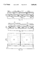
- FIG. 8 is a view, in partial cross section, of the preferred embodiment MPSLM.
- FIGS. 9-17 are partial cross section views of the preferred embodiment MPSLM after subsequent processing steps.
- FIG. 18 is a plan view of the preferred embodiment MPSLM with phantom lines illustrating underlying "hidden hinge” and beam structure.
- FIG. 19 is a perspective view of the preferred embodiment MPSLM.
- FIG. 20 is a block diagram of an optical signal processor incorporating an array of preferred embodiment MPSLM's.
- modulation In the field of signal processing, modulation generally refers to the process of varying the amplitude, frequency, or phase of a carrier signal.
- the unmodulated carrier signal is a wave of energy of constant frequency. This energy may be sound, light, or radio waves.
- the important feature of energy waves is that, although sometimes they may be conducted through matter, it is only the energy itself that moves.
- the ripples spread out from the point where the stone hits the water.
- These waves are not made up of water traveling outward. Instead, the water at the surface of the pond just rises and falls, and only the energy moves outward.
- light or sound waves consist of a regular rise and fall of energy.
- the distance between successive energy rises is the wavelength
- the rate at which they pass is the wave's frequency (in music, the frequency is the same as the pitch of the sound)
- the difference between their high and low energy states is their amplitude
- the condition of the wave in a single moment and place in time is its phase (in other words, there are 360 degrees or 2 ⁇ radians of phase between successive energy rises--180 degrees or ⁇ radians of phase between an energy maxima and an energy minima).
- waves may bring not just energy but also communicate meaning. Waves that are constant, for example as in the beam of a flashlight, cannot convey any information. But if that beam is interrupted, or if its brightness can be made to change, then it can carry a message. This is how all wave-borne communications work.
- Amplitude modulation is analogous to a trombonist playing a constant note or pitch, but varying the volume of the sound of the trombone.
- Frequency modulation is analogous to a trombonist playing a constant pitch, but oscillating the slide of the trombone about the position corresponding to the constant, unmodulated pitch--resulting in a vibrato or a sound which tremors about the constant pitch.
- the sound of a trombone many feet away travels to the audience in generally planar waves--surfaces of equal energy travelling at an equal speed away from the trombone. Listeners at equal distances from the trombone would receive the sound in the same phase.
- the trombonist can transmit and detect these phase differences in an analogous manner.
- information can be transmitted by modulating a constant frequency, or carrier, signal of light and imparting and detecting changes of amplitude, frequency and phase.
- the preferred embodiment of the present invention is capable of doing this with the phase of light signals.
- a laser light which has an approximately constant frequency, and wavefronts of nearly uniform phase shines onto an array of Spatial Light Modulators (SLM).
- SLM Spatial Light Modulators
- the preferred embodiment of the present inventions modulates the continuously varying phase of the incident light, and induces discrete phase changes depending on the information which is being transmitted. Just as time is continuous, as can be seen in the movement of a clock's second hand, so is the phase of a light signal. Time is measured, however, in discrete units: hours, minutes, seconds, and portions of seconds. The more sub-units (1/4, 1/2, 3/4 hours vs. 1/8, 1/4, 3/8, 1/2, 5/8, 3/4, 7/8 hours) a unit (hour) can be broken into, the more accurately the representation of time can be made.
- phase of a signal so the preferred embodiment of the present invention makes it possible to break the phase easily into sub-units while still using digital signals, typically binary addressing signals, such as those from a typical computer.
- digital signals typically binary addressing signals, such as those from a typical computer.
- the phase modulation of the preferred embodiment works by combining the light from two or more sub-elements into a single element. For instance, if light incident on a pixel with two sub-elements, and a phase change of 0 radians is induced on a first sub-element, and of ⁇ /2 radians on a second sub-element, and if light reflected from both elements has the same amplitude, then the light reflected from both sub-elements will have a net phase change of ⁇ /4.
- FIG. 1 A preferred embodiment of the present invention is shown in FIG. 1.
- This embodiment consists of a pixel 20 consisting of one phase modulating element 22 that switches between zero and ⁇ radians and a second modulating element 24 that switches between ⁇ /2 and 3 ⁇ /2 radians.
- the net response of the pixel will have the four possible phase states shown in FIGS. 2a-2b, (e.g., ⁇ /4, 3 ⁇ /4, 5 ⁇ /4, and 7 ⁇ /4).
- the amplitude of the response at these phase states is 1/ ⁇ 2 or 0.707 due to the addition of two equal components with a phase difference of ⁇ /2 radians (if the two halves were to be set to exactly the same phase the amplitude would sum to 1).
- phase is a relative quantity
- the phase measurements can be referenced to the ⁇ /4 state (i.e. the ⁇ /4 state may be called the zero phase state).
- the four phase states of this modulating element can be called 0, ⁇ /2, ⁇ , and 3 ⁇ /2 radians.
- FIG. 3 Another embodiment of this invention is shown in FIG. 3.
- this pixel 30 there are four independently addressable modulating elements.
- First and second elements 32, 34 switch between zero and ⁇ radians.
- Third element 36 and a fourth element 38 switch between ⁇ /2 and 3 ⁇ /2 radians.
- the different phase states shown in FIG. 4 can be achieved.
- One advantage of this pixel structure is its modulation characteristics as shown in FIG. 4 allows for eight different phase states each with approximately the same amplitude. The modulation characteristics further allow for a zero amplitude state.
- the layout of this pixel 30 is directly compatible with addressing circuitry that has been developed for display devices that utilize binary addressing circuitry.
- the regular square configuration of the modulating elements 32, 34, 36, and 38 can be added on to the existing binary addressing circuitry with no changes in the underlying address structures.
- This pixel 40 consists of three modulator elements, one pixel 42 switches between zero and ⁇ radians, a second pixel 44 switches between ⁇ /3 and 4 ⁇ /3 radians, and a third pixel 46 switches between 2 ⁇ /3 and 5 ⁇ /3 radians.
- the combination of these elements when properly resolved gives the seven response states shown in FIG. 6.
- the modulation characteristics for this embodiment also have a zero amplitude state and all of the six phase states have exactly the same amplitude (2/3 of the response if all were of equal phase).
- the preferred embodiment multiphase pixel is a deformable mirror light modulator.
- pixels described above can be implemented in any type of light modulator that has the ability to switch between two phase states.
- a mask must be placed over the modulator element array to introduce the necessary phase offsets so that adjacent elements switch between orthogonal phase states.
- the mask arrangement for polarization rotating light modulators such as magnetooptic devices or binary liquid crystal devices is shown in the device 50 of FIG. 7.
- the active pixels 56 and 58 are interposed between the polarizer 52 and analyzer 54.
- the mask 60 is added after the analyzer 54.
- Section 62 comprises an area of mask 60 of a first selected thickness. Light passing through the first active pixel 56 and section 62 will have a reference phase.
- Section 64 comprises another area of mask of another selected thickness.
- Second active pixel 58 and section 64 Light passing through the second active pixel 58 and section 64 will introduce an additional phase change required to have second active pixel 58 operating between phase states that are orthogonal to those of the first active pixel.
- the mask 60 is added after the analyzer to ensure that the phase change does not change the operation of the polarizer/analyzer pair.
- multi-phase modulator pixel or macroelement is a subunit comprising two elements, a first element which can alternate in phase between zero and ⁇ radians, and a second element which can vary between ⁇ /2 and 3 ⁇ /2 radians.
- FIG. 8 shows an implementation of this concept in a partial cross section of a single macroelement 70 within a Deformable Mirror Device (DMD).
- Each macroelement comprises a first mirror 72 and a second mirror 74.
- Each mirror is constrained to move vertically a distance corresponding to an odd multiple of ⁇ /2 radians of the phase of the incident illumination. The movement of each mirror is effected by applying a voltage between first or second element beam 104, 106 and an underlying address electrode 80.
- Beam element 104, 106 is connected to underlying bias circuitry through base pads 78, hinges 96, 98, and hinge supports 100, 102.
- a beam element 104 or 106 and an underlying address electrode 80 form the two plates of an air gap capacitor and the opposite charges induced on the two plates by the applied voltage exert electrostatic force attracting beam element 104 or 106 to an underlying address electrode 80.
- the address voltage applied to beam element 104 or 106 is such that the beam element 104, 106 deflects until it contacts underlying insulating stops 82.
- the motion of the beam elements 104, 106 is reflected in the mirror elements 72, 74 which are formed above the beam elements 104, 106.
- a deflected mirror 72, 74 will then cause an optical path change of n ⁇ radians (where n is odd).
- the first mirror 72 is defined as zero radians when not deflected, and hence will vary in phase between zero and n ⁇ radians (n odd).
- the second mirror 74 is built such that when the DMD is in its quiescent state, the surface of mirror 74 surface is displaced from the surface of the first mirror 72 by an odd multiple of ⁇ /4 radians, again so that the optical path difference between the two types of mirror is m ⁇ /2 radians (where m is odd).
- the fabrication process can be extended to more than two mirrors per subpixel in order to make more phases accessible.
- a three-mirror subpixel can be built if the three mirrors are constructed to move respectively between zero and ⁇ /2 radians, ⁇ /6 radians and 2 ⁇ /3 radians, and ⁇ /3 radians and 5 ⁇ /6 radians.
- MPSLM Multiple Phase Spatial Light Modulator
- Address circuit fabrication may then be followed by a modified "Hidden Hinge DMD” process flow, as disclosed in U.S. Pat. No. 5,083,857, to build up the mirror substructure.
- the "Hidden Hinge DMD” process and structure is modified by adding a subsequent layer to an adjacent mirror element to introduce a phase change relative to an unmodified element.
- the "Hidden Hinge DMD” process flow is incorporated in the preferred embodiment of the present invention, although the present invention may be applied to many other methods and structures for light modulation.
- a substrate 76 is provided and a metal layer is formed and patterned to provide base pads 78 for support vias as well as address electrodes 80 which are in electrical communication with the underlying CMOS address circuitry.
- this underlying CMOS address circuitry can be similar to DRAM or SRAM address array.
- the preferred method of fabrication would be to put one or more insulating stops 82 directly on the electrode 80 underlying the mirror 72 or 74. This step preferably comprises a low temperature a plasma oxide deposition (preferably less than 5000 ⁇ ). The stops 82 are then patterned and etched.
- FIG. 9c shows the preferred embodiment DMD after a first spacer layer 84 is deposited and patterned.
- the first spacer layer 84 is spun on to planarize the electrode and stop topography.
- the thickness of the first spacer layer 84 is critical.
- the total spacer 84 thickness (T sp ) must be equal to the stop 82 height (T st ) plus an odd multiple of quarter wavelengths (m ⁇ /4, m odd) of the incident illumination.
- beams 104 and 106 (not shown, see FIG. 9e) and the mirrors 72 and 74 (not shown, see FIG. 8) built upon beams 104 and 106 will deflect through a selected distance, L, left between the hinge elements 96, 98 (not shown, see FIG.
- the mirrors must be able to travel m ⁇ /4 or 1582 ⁇ , 4746 ⁇ , 7910 ⁇ , etc.
- the first spacer layer thickness is 6200 ⁇ , so oxide stops 82 will preferably be 1454 ⁇ thick.
- the first spacer layer 84 is then patterned with hinge support via cavities 86 formed over the via pads 78 and UV hardened.
- Thin hinge aluminum alloy 88 is sputtered onto the first spacer layer 84 and low temperature plasma oxide is deposited onto the hinge aluminum 88 and patterned to form the buried hinge etch stop 90.
- first element hinges 96 are formed, one or more second element hinges 98 are formed, one or more first element hinge supports 100 are formed, one or more second element hinge supports 102 are formed, a first element beam 104 is formed, and a second element beam 106 is formed.
- Further plasma etch is used to remove the oxide masks 90 and 94, and it must be selective against spacer etch. Unlike usual DMD process flows, first spacer layer 84 is not removed after the hidden hinge oxide strip.
- Second spacer layer 108 must be of sufficient depth that when the mirrors 72 and 74 are deflected the mirror does not hit the hinge supports 102 and 104. In the preferred embodiment the mirror deflection distance is 4746 ⁇ , so the preferred spacer thickness of 6200 ⁇ will be sufficient.
- Mirror support via cavities 110 above beams 104, 106 are next patterned and UV-hardened.
- mirror aluminum 112 is deposited, and low temperature plasma oxide is deposited and etched to form the "hidden mirror” aluminum etch mask 114.
- an additional layer of aluminum 116 is deposited which is will be responsible for the phase difference between the quiescent mirrors.
- Oxide is again deposited and etched to form an aluminum etch mask 118 for the first mirror 72. All of the first mirror 72 aluminum is protected by the etch mask 118. The subsequent etch, preferably a plasma etch, will etch down to the oxide mask 114 over the second mirror 74, removing the extra n ⁇ /8 of aluminum from the surface of the second mirror 74.
- the semiconductor wafer (not shown) is then sawn and undercut as usual.
- the oxide masks 114 and 118 will be stripped and the spacer layers 84 and 108 will be removed, leaving two out of phase mirrors 72 and 74 supported by identical deformable substructures.
- FIG. 10 shows a plan (top) view of the DMD macroelement 70. Showing the cross section through which FIG. 9a through 9i have been taken. Note that by using the hidden hinge structure, a great amount of surface area is actually the mirror elements 72 and 74. In this manner the "hidden hinge" structure is fairly efficient, modulating much of the incident optical energy.
- FIG. 11 shows a perspective view of the DMD macroelement 70.
- FIG. 12 shows a block diagram of an optical signal processor 200 incorporating the preferred embodiment DMD.
- the preferred embodiment optical signal processor shown here is an optical correlator.
- the optical correlator's operation described below is exemplary.
- the DMD of this invention may be utilized in many types of structures. It is to be understood that the scope of the invention also comprehends embodiments different from those described, yet within the scope of the claims.
- a coherent light source 202 shines coherent light 204 upon an optical transmissive/reflective element 206.
- This optical element 206 substantially reflects the light from the light source 202 onto a first array 208 of preferred embodiment DMD's 70 (not shown, see FIG. 9).
- This first array 208 carries the input image placed on it by the input image sensor 210.
- This image is modulated onto the light signal 204 by the first array 208, and this modulated light 212 is directed towards optical element 206.
- Optical element 206 allows a substantial amount of modulated light 202 to pass through toward a lens 214.
- Lens 214 serves to perform a Fourier transform on the modulated light 212, as is well known in the art, resulting in a spatial frequency light signal 216 which is directed towards second array 218 of preferred embodiment DMD's 70 (not shown, see FIG. 9).
- This second array 218 carries a selected filter image placed on it by filter data base 220.
- Second array 218 modulated the spatial frequency light signal 216 with its filter image and directs the filtered signal 222 toward lens 214.
- Lens 214 serves to perform an inverse Fourier transform of filtered signal 222, as is well known in the art, resulting in an output correlation signal 224.
- This output correlation signal is now substantially reflected by optical element 206 and directed toward a CCD imager 226 which outputs an optical correlation map 228.
- Optical correlation map 228 shows the degree of correlation between the input image and the filter image and the location of the filter object in the input scene as is well known in the art.
- light source 202 is a laser diode which outputs coherent light 204.
- the optical element 206 operates to reflect light of one polarization, and transmit light of another polarization. The various light signals which pass through optical element 206 are imparted the needed polarization to either be reflected or transmitted by the optical element 206 as needed.
- Lens 214 may be a single or multiple lens system.
- DMD 70, mirror 72 and mirror 74 are deflected equal amounts. As an alternative these mirrors could have differing travels.
- spacer layers 84, and 108 are completely removed subsequent to wafer sawing and undercut. In the alternative, these layers 84 and 104 may be removed at any time subsequent to beam 100 and 112 fabrication.
- metal vias support the hinge/beam layers 96/100 and mirrors 72 and 74.
- photoresist spacer 84, 108 may be selectively etched to remain in these areas as support vias.
- the preferable metalizations comprise aluminum, although alternative metals such as titanium, gold, nickel or other metals or metal alloys can be used.
- Stops 82 are described in the preferred embodiment as insulating stops, but any material may be used which provides the appropriate durability, as long as the device structure is such that electrical isolation is maintained regardless of mirror deflection.
- the underlying circuitry is preferably a DRAM or SRAMtype structure, but a charge coupled device (CCD) or other type of circuitry could perform the function depending on the type of performance desired.
- the preferred embodiment comprised a two-mirror macroelement.
- a three mirror (or more) macroelement the flow could be expanded as follows:
- FIG. 9a through 9g proceed in the same fashion, except electrodes and hidden hinge substructure for a third mirror is included.
- an additional aluminum deposition and oxide mask deposition is required for the third mirror.
- These layers are formed in a similar fashion to aluminum film 116 and oxide mask 118.
- the aluminum film would be 2110 ⁇ , to put another 4 ⁇ /3 radians of reflected optical path difference between mirrors two and three.
- the preferred embodiment has generally been described as using a modulation technique in which the viewing angle is perpendicular to the surfaces of the pixels, such that the path differences between adjacent pixels is determined solely by the different levels of aluminum film deposited on the adjacent pixels.
- the invention described herein might also used with viewing angles that are other than perpendicular to the pixel surfaces. The scope of the invention should be determined by the claims set out hereinbelow.
Abstract
A method for multiple phase light modulation, said method comprising providing a pixel (20) having at least two modulating elements (22), (24). The method further comprising addressing said at least two modulating elements (22), (24) whereby light incident on said addressed element undergoes discrete phase changes between addressable states. The method further comprises resolving light from said at least two modulating elements (22), (24), into a response having at least three unique phases. Other devices, systems and methods are also disclosed.
Description
This is a divisional of application Ser. No. 07/862,933, filed Apr. 3, 1992 now U.S. Pat. No. 5,312,513.
This invention generally relates to multiple phase spatial light modulation, and more specifically to the operation and fabrication of a light modulator that is addressed by discrete level address circuitry but is capable of multiple phase states for light modulation.
Spatial light modulators (SLM) are transducers that modulate incident light in a spatial pattern corresponding to an electrical or optical input. The incident light may be modulated in its phase, intensity, polarization, or direction, and the light modulation may be achieved by a variety of material exhibiting various electrooptic or magnetooptic effects and by materials that modulate light by surface deformation. SLM's have found numerous applications in the areas of optical information processing, projections displays, and electrostatic printing. See references cited in L. Hornbeck, 128×128 Deformable Mirror Device, 30 IEEE Tran. Elec. Dev. 539 (1983).
Heretofore, in this field, a number of methods have been applied to achieve more than two phase and/or amplitude states in binary light modulators. Virtually all of these have been applied to magnetooptic modulators which are inherently binary but some can be applied to other modulators that are simply run in a binary fashion. Flannery et al., "Transform-ratio Ternary Phase-amplitude Filter Formulation for Improved Correlation Discrimination", Applied Optics 27, 4079-4083 (1988) and Kast et al., "Implementation of Ternary Phase Amplitude Filters Using a Magnetooptic Spatial Light Modulator", Applied Optics 28, 1044-1046 (1989) have described methods of using a ternary state that can be accessed in a magnetooptic modulator. Magnetooptic devices operate by switching the direction of the magnetic domain in a transmissive garnet material. The domain direction can have only two states which leads to the inherently binary nature of the device.
A major disadvantage of the binary holograms and filters is that the binary representation is identical for both a hologram (or filter) and its complex conjugate. This means that when a binary hologram is reconstructed, both the desired image and a spatially reversed copy of the image (flipped in both the horizontal and vertical directions) are produced. Since neither the image nor its conjugate are preferred in this reconstruction, the total energy in the output is divided equally between the images reducing the efficiency of the process. In addition, the two reconstructions will overlap each other spatially unless special techniques such as spatial carriers are employed to separate these two images. Spatial carrier modulation will further reduce the overall efficiency of the reconstruction process.
Dickey and Hansche, "Quad-phase Correlation Filter Implementations", Applied Optics 28, 4840-4844 (1989) have described a method of using a binary state magnetooptic device to achieve four phase levels for correlation filters. The method uses a detour phase approach by operating the device aligned slightly off axis. The tilt used to give this misalignment provides a π/2 phase difference between adjacent pixels in the modulator in the tilt direction. By setting the processing resolution such that the responses from adjacent pixels mix together to give the net response, four phase states are possible: (±1±j)/√2, (i.e., π/4, 3π/4, 5π/4, and 7π/4 radians). The technique requires critical alignment tolerances.
In U.S. Ser. No. 590,405 filed Sep. 28, 1990, Florence has shown that full complex light modulation is possible by mixing the response of two adjacent phase modulating elements with analog addressing. The separate addressing of the two modulating elements provides the two degrees of freedom required to independently set both amplitude and phase in the combined pixel response. Although this method is quite general and provides complete modulation range in both amplitude and phase, it requires analog addressing circuitry.
The preferred embodiment of the present invention in large measure overcomes the aforementioned difficulties. The preferred embodiment provides for reprogrammable methods for image filtering, correlation, reconstruction of holographic images, and information or detail enhancement using complex modulation in the Fourier plane. The preferred embodiment of the present invention provides for phase-only modulation having greater optical efficiency than full complex modulation, since no light is removed by amplitude attenuation. The preferred embodiment further utilizes the advantages of binary addressing circuitry which requires significantly less memory for filter storage relative to an analog phase representation and is also substantially simpler to manufacture and operate than one which must provide specific analog addressing levels.
The preferred embodiment also provides for multiple phase levels for complex modulation, and further provides for a zero amplitude state. The advantage of having a zero amplitude state is that in certain regions of the filter plane, noise can be removed where very little or no signal energy will be lost. Thus, signal-to-noise ratios can be improved with little effect on optical efficiency.
The preferred embodiment further accomplishes the aforementioned advantages without the critical alignment difficulties mentioned in the prior art devices.
In the drawings:
FIG. 1 is a plan view of a preferred embodiment two element Multiple Phase Spatial Light Modulator (MPSLM).
FIGS. 2a-2b is the resulting phase diagram for the modulating device of FIG. 1.
FIG. 3 is a plan view of a preferred embodiment four element MPSLM.
FIG. 4 is the resulting phase diagram for modulating device of FIG. 3.
FIG. 5 is a plan view of a preferred embodiment three element MPSLM.
FIG. 6 is the resulting phase diagram for modulating device of FIG. 5.
FIG. 7 is a plan view of an alternate embodiment two element MPSLM.
FIG. 8 is a view, in partial cross section, of the preferred embodiment MPSLM.
FIGS. 9-17 are partial cross section views of the preferred embodiment MPSLM after subsequent processing steps.
FIG. 18 is a plan view of the preferred embodiment MPSLM with phantom lines illustrating underlying "hidden hinge" and beam structure.
FIG. 19 is a perspective view of the preferred embodiment MPSLM.
FIG. 20 is a block diagram of an optical signal processor incorporating an array of preferred embodiment MPSLM's.
Corresponding numerals and symbols in the different figures refer to corresponding parts unless otherwise indicated.
In the field of signal processing, modulation generally refers to the process of varying the amplitude, frequency, or phase of a carrier signal. The unmodulated carrier signal is a wave of energy of constant frequency. This energy may be sound, light, or radio waves. The important feature of energy waves is that, although sometimes they may be conducted through matter, it is only the energy itself that moves. When a stone is dropped into a pond, for example, the ripples spread out from the point where the stone hits the water. These waves, however, are not made up of water traveling outward. Instead, the water at the surface of the pond just rises and falls, and only the energy moves outward. In the same way, light or sound waves consist of a regular rise and fall of energy. The distance between successive energy rises is the wavelength, the rate at which they pass is the wave's frequency (in music, the frequency is the same as the pitch of the sound), the difference between their high and low energy states is their amplitude, and the condition of the wave in a single moment and place in time is its phase (in other words, there are 360 degrees or 2π radians of phase between successive energy rises--180 degrees or π radians of phase between an energy maxima and an energy minima). In traveling to us and through us, waves may bring not just energy but also communicate meaning. Waves that are constant, for example as in the beam of a flashlight, cannot convey any information. But if that beam is interrupted, or if its brightness can be made to change, then it can carry a message. This is how all wave-borne communications work.
Amplitude modulation is analogous to a trombonist playing a constant note or pitch, but varying the volume of the sound of the trombone. Frequency modulation is analogous to a trombonist playing a constant pitch, but oscillating the slide of the trombone about the position corresponding to the constant, unmodulated pitch--resulting in a vibrato or a sound which tremors about the constant pitch. The sound of a trombone many feet away travels to the audience in generally planar waves--surfaces of equal energy travelling at an equal speed away from the trombone. Listeners at equal distances from the trombone would receive the sound in the same phase. If the signal had to travel slightly further, or was made to travel slightly more slowly to one listener than the other, than they would receive the sound in a different phase. Although the human ear generally cannot detect phase differences and the trombonist is incapable of modulating the phase as he did with the amplitude and frequency, various electronic devices can transmit and detect these phase differences in an analogous manner. In the same manner as the trombonist, information can be transmitted by modulating a constant frequency, or carrier, signal of light and imparting and detecting changes of amplitude, frequency and phase. The preferred embodiment of the present invention is capable of doing this with the phase of light signals. In the preferred embodiment, a laser light (which has an approximately constant frequency, and wavefronts of nearly uniform phase) shines onto an array of Spatial Light Modulators (SLM). Information is put on this array, typically by a computer, and is now a part of the light signal which is reflected from the preferred embodiment invention. The preferred embodiment of the present inventions modulates the continuously varying phase of the incident light, and induces discrete phase changes depending on the information which is being transmitted. Just as time is continuous, as can be seen in the movement of a clock's second hand, so is the phase of a light signal. Time is measured, however, in discrete units: hours, minutes, seconds, and portions of seconds. The more sub-units (1/4, 1/2, 3/4 hours vs. 1/8, 1/4, 3/8, 1/2, 5/8, 3/4, 7/8 hours) a unit (hour) can be broken into, the more accurately the representation of time can be made. The same is true with phase of a signal, so the preferred embodiment of the present invention makes it possible to break the phase easily into sub-units while still using digital signals, typically binary addressing signals, such as those from a typical computer. By using individually addressed and singly combined sub-elements of a single pixel, it is possible to readily modulate the carrier signal between more than two phases, which is all that has been possible with prior art spatial light modulators with binary addressing.
The phase modulation of the preferred embodiment works by combining the light from two or more sub-elements into a single element. For instance, if light incident on a pixel with two sub-elements, and a phase change of 0 radians is induced on a first sub-element, and of π/2 radians on a second sub-element, and if light reflected from both elements has the same amplitude, then the light reflected from both sub-elements will have a net phase change of π/4. Similarly if a phase change of π radians is induced on a first sub-element, and of π/2 radians on a second sub-element, and if light reflected from both elements has the same amplitude, then the light reflected from both sub-elements will have a net phase change of 3π/4.
A preferred embodiment of the present invention is shown in FIG. 1. This embodiment consists of a pixel 20 consisting of one phase modulating element 22 that switches between zero and π radians and a second modulating element 24 that switches between π/2 and 3π/2 radians. With the optical system resolution set to mix the response of these two elements, the net response of the pixel will have the four possible phase states shown in FIGS. 2a-2b, (e.g., π/4, 3π/4, 5π/4, and 7π/4). The amplitude of the response at these phase states is 1/√2 or 0.707 due to the addition of two equal components with a phase difference of π/2 radians (if the two halves were to be set to exactly the same phase the amplitude would sum to 1). Furthermore, since phase is a relative quantity, the phase measurements can be referenced to the π/4 state (i.e. the π/4 state may be called the zero phase state). Then, the four phase states of this modulating element can be called 0, π/2, π, and 3π/2 radians.
Another embodiment of this invention is shown in FIG. 3. In this pixel 30 there are four independently addressable modulating elements. First and second elements 32, 34 switch between zero and π radians. Third element 36 and a fourth element 38 switch between π/2 and 3π/2 radians. Again setting the optical system resolution to mix the response of these elements into a single response, the different phase states shown in FIG. 4 can be achieved. One advantage of this pixel structure is its modulation characteristics as shown in FIG. 4 allows for eight different phase states each with approximately the same amplitude. The modulation characteristics further allow for a zero amplitude state. Still further, the layout of this pixel 30 is directly compatible with addressing circuitry that has been developed for display devices that utilize binary addressing circuitry. The regular square configuration of the modulating elements 32, 34, 36, and 38 can be added on to the existing binary addressing circuitry with no changes in the underlying address structures.
The concept described can be extended to devices that switch between phase states that are not orthogonal. The embodiment shown in FIG. 5 is an example of this. This pixel 40 consists of three modulator elements, one pixel 42 switches between zero and π radians, a second pixel 44 switches between π/3 and 4π/3 radians, and a third pixel 46 switches between 2π/3 and 5π/3 radians. The combination of these elements when properly resolved gives the seven response states shown in FIG. 6. The modulation characteristics for this embodiment also have a zero amplitude state and all of the six phase states have exactly the same amplitude (2/3 of the response if all were of equal phase).
The preferred embodiment multiphase pixel is a deformable mirror light modulator. In alternate embodiments, pixels described above can be implemented in any type of light modulator that has the ability to switch between two phase states.
In many of the alternate embodiments, a mask must be placed over the modulator element array to introduce the necessary phase offsets so that adjacent elements switch between orthogonal phase states. The mask arrangement for polarization rotating light modulators such as magnetooptic devices or binary liquid crystal devices is shown in the device 50 of FIG. 7. In this arrangement, the active pixels 56 and 58 are interposed between the polarizer 52 and analyzer 54. The mask 60 is added after the analyzer 54. Section 62 comprises an area of mask 60 of a first selected thickness. Light passing through the first active pixel 56 and section 62 will have a reference phase. Section 64 comprises another area of mask of another selected thickness. Light passing through the second active pixel 58 and section 64 will introduce an additional phase change required to have second active pixel 58 operating between phase states that are orthogonal to those of the first active pixel. The mask 60 is added after the analyzer to ensure that the phase change does not change the operation of the polarizer/analyzer pair.
As outlined above the preferred embodiment multi-phase modulator pixel or macroelement is a subunit comprising two elements, a first element which can alternate in phase between zero and π radians, and a second element which can vary between π/2 and 3π/2 radians. FIG. 8 shows an implementation of this concept in a partial cross section of a single macroelement 70 within a Deformable Mirror Device (DMD). Each macroelement comprises a first mirror 72 and a second mirror 74. Each mirror is constrained to move vertically a distance corresponding to an odd multiple of π/2 radians of the phase of the incident illumination. The movement of each mirror is effected by applying a voltage between first or second element beam 104, 106 and an underlying address electrode 80. Beam element 104, 106 is connected to underlying bias circuitry through base pads 78, hinges 96, 98, and hinge supports 100, 102. A beam element 104 or 106 and an underlying address electrode 80 form the two plates of an air gap capacitor and the opposite charges induced on the two plates by the applied voltage exert electrostatic force attracting beam element 104 or 106 to an underlying address electrode 80. This causes beam element 104 or 106 to twist at associated hinges 96 or 98 (and possibly other hinges not shown) and be deflected toward underlying address electrode 80. The address voltage applied to beam element 104 or 106 is such that the beam element 104, 106 deflects until it contacts underlying insulating stops 82. The motion of the beam elements 104, 106 is reflected in the mirror elements 72, 74 which are formed above the beam elements 104, 106. A deflected mirror 72, 74 will then cause an optical path change of nπ radians (where n is odd). The first mirror 72 is defined as zero radians when not deflected, and hence will vary in phase between zero and nπ radians (n odd). The second mirror 74 is built such that when the DMD is in its quiescent state, the surface of mirror 74 surface is displaced from the surface of the first mirror 72 by an odd multiple of π/4 radians, again so that the optical path difference between the two types of mirror is mπ/2 radians (where m is odd).
The fabrication process can be extended to more than two mirrors per subpixel in order to make more phases accessible. For example, a three-mirror subpixel can be built if the three mirrors are constructed to move respectively between zero and π/2 radians, π/6 radians and 2π/3 radians, and π/3 radians and 5π/6 radians.
Fabrication of the Multiple Phase Spatial Light Modulator (MPSLM) begins with construction of the underlying CMOS circuitry. This can be the "standard" DRAM or SRAM array used in DMD projection display. For the MPSLM, however, the pixels can be thought of as grouped to form macropixels. This is an operational, rather than physical grouping. The physical array is identical to the DRAM or SRAM address array.
Address circuit fabrication may then be followed by a modified "Hidden Hinge DMD" process flow, as disclosed in U.S. Pat. No. 5,083,857, to build up the mirror substructure. The "Hidden Hinge DMD" process and structure is modified by adding a subsequent layer to an adjacent mirror element to introduce a phase change relative to an unmodified element. The "Hidden Hinge DMD" process flow is incorporated in the preferred embodiment of the present invention, although the present invention may be applied to many other methods and structures for light modulation.
With reference to FIG. 9a, a substrate 76 is provided and a metal layer is formed and patterned to provide base pads 78 for support vias as well as address electrodes 80 which are in electrical communication with the underlying CMOS address circuitry. As mentioned above this underlying CMOS address circuitry can be similar to DRAM or SRAM address array.
Referring now to FIG. 9b, in order to control the travel of the mirrors 72 or 74 it is necessary to build a stop. The preferred method of fabrication would be to put one or more insulating stops 82 directly on the electrode 80 underlying the mirror 72 or 74. This step preferably comprises a low temperature a plasma oxide deposition (preferably less than 5000 Å). The stops 82 are then patterned and etched.
FIG. 9c shows the preferred embodiment DMD after a first spacer layer 84 is deposited and patterned. The first spacer layer 84 is spun on to planarize the electrode and stop topography. The thickness of the first spacer layer 84 is critical. The total spacer 84 thickness (Tsp) must be equal to the stop 82 height (Tst) plus an odd multiple of quarter wavelengths (mλ/4, m odd) of the incident illumination. In this manner beams 104 and 106 (not shown, see FIG. 9e) and the mirrors 72 and 74 (not shown, see FIG. 8) built upon beams 104 and 106 will deflect through a selected distance, L, left between the hinge elements 96, 98 (not shown, see FIG. 9e) and the top of the dielectric stop 82 by subsequent removal of the first spacer layer 84 (L=mλ/4, m odd=Tsp -Tst). Thus, the total first spacer layer 84 thickness (Tsp) is formed so the optical path length difference between light reflected from an nondeflected mirror and light reflected from the same mirror deflected through selected distance L (L=mλ/4, m odd) is mπ/2 (m odd). In the preferred embodiment of the present invention, assume 6328 Å illumination. For a path length difference of mπ (m odd) between mirrors, the mirrors must be able to travel mλ/4 or 1582 Å, 4746 Å, 7910 Å, etc. In the preferred embodiment, m=3 is chosen for 4746 Å of deflection. Preferably, the first spacer layer thickness is 6200 Å, so oxide stops 82 will preferably be 1454 Å thick. The first spacer layer 84 is then patterned with hinge support via cavities 86 formed over the via pads 78 and UV hardened.
Referring now to FIG. 9d, the "Hidden hinge" substructure is now fabricated. Thin hinge aluminum alloy 88 is sputtered onto the first spacer layer 84 and low temperature plasma oxide is deposited onto the hinge aluminum 88 and patterned to form the buried hinge etch stop 90.
With reference to FIG. 9e, Beam aluminum is deposited, and another low temperature plasma oxide layer is deposited onto it and patterned to form a beam aluminum etch stop 94 in a similar manner to buried hinge etch stop 90. An aluminum etch is now performed clearing beam aluminum in areas not covered by beam aluminum etch stop 94 and hinge aluminum 88 not covered by the hinge aluminum etch stop 90. In this manner first element hinges 96 are formed, one or more second element hinges 98 are formed, one or more first element hinge supports 100 are formed, one or more second element hinge supports 102 are formed, a first element beam 104 is formed, and a second element beam 106 is formed. Further plasma etch is used to remove the oxide masks 90 and 94, and it must be selective against spacer etch. Unlike usual DMD process flows, first spacer layer 84 is not removed after the hidden hinge oxide strip.
Referring to FIG. 9f, a second spacer layer 108 is now spun on. Second spacer layer 108 must be of sufficient depth that when the mirrors 72 and 74 are deflected the mirror does not hit the hinge supports 102 and 104. In the preferred embodiment the mirror deflection distance is 4746 Å, so the preferred spacer thickness of 6200 Å will be sufficient. Mirror support via cavities 110 above beams 104, 106 are next patterned and UV-hardened.
Now referring to FIG. 9g, mirror aluminum 112 is deposited, and low temperature plasma oxide is deposited and etched to form the "hidden mirror" aluminum etch mask 114.
With reference to FIG. 9h, an additional layer of aluminum 116 is deposited which is will be responsible for the phase difference between the quiescent mirrors. The thickness of aluminum 116 shall preferably be equal to nλ/8 (n odd), so on reflection the path difference between the quiescent mirrors will be nλ/4. For the preferred incident light λ=6328 Å, this thickness can be 791 Å, 2373 Å, 3955 Å, 5537 Å, etc. Preferably, aluminum 116 thickness will be 2373 Å, for n=3. Oxide is again deposited and etched to form an aluminum etch mask 118 for the first mirror 72. All of the first mirror 72 aluminum is protected by the etch mask 118. The subsequent etch, preferably a plasma etch, will etch down to the oxide mask 114 over the second mirror 74, removing the extra nλ/8 of aluminum from the surface of the second mirror 74.
With reference to FIG. 9i, the semiconductor wafer (not shown) is then sawn and undercut as usual. The oxide masks 114 and 118 will be stripped and the spacer layers 84 and 108 will be removed, leaving two out of phase mirrors 72 and 74 supported by identical deformable substructures.
FIG. 10 shows a plan (top) view of the DMD macroelement 70. Showing the cross section through which FIG. 9a through 9i have been taken. Note that by using the hidden hinge structure, a great amount of surface area is actually the mirror elements 72 and 74. In this manner the "hidden hinge" structure is fairly efficient, modulating much of the incident optical energy.
FIG. 11 shows a perspective view of the DMD macroelement 70.
FIG. 12 shows a block diagram of an optical signal processor 200 incorporating the preferred embodiment DMD. The preferred embodiment optical signal processor shown here is an optical correlator. The optical correlator's operation described below is exemplary. The DMD of this invention may be utilized in many types of structures. It is to be understood that the scope of the invention also comprehends embodiments different from those described, yet within the scope of the claims.
In the optical signal processor 200, a coherent light source 202 shines coherent light 204 upon an optical transmissive/reflective element 206. This optical element 206 substantially reflects the light from the light source 202 onto a first array 208 of preferred embodiment DMD's 70 (not shown, see FIG. 9). This first array 208 carries the input image placed on it by the input image sensor 210. This image is modulated onto the light signal 204 by the first array 208, and this modulated light 212 is directed towards optical element 206. Optical element 206 allows a substantial amount of modulated light 202 to pass through toward a lens 214. Lens 214 serves to perform a Fourier transform on the modulated light 212, as is well known in the art, resulting in a spatial frequency light signal 216 which is directed towards second array 218 of preferred embodiment DMD's 70 (not shown, see FIG. 9). This second array 218 carries a selected filter image placed on it by filter data base 220. Second array 218 modulated the spatial frequency light signal 216 with its filter image and directs the filtered signal 222 toward lens 214. Lens 214 serves to perform an inverse Fourier transform of filtered signal 222, as is well known in the art, resulting in an output correlation signal 224. This output correlation signal is now substantially reflected by optical element 206 and directed toward a CCD imager 226 which outputs an optical correlation map 228. Optical correlation map 228 shows the degree of correlation between the input image and the filter image and the location of the filter object in the input scene as is well known in the art. In the preferred embodiment light source 202 is a laser diode which outputs coherent light 204. Preferably, the optical element 206 operates to reflect light of one polarization, and transmit light of another polarization. The various light signals which pass through optical element 206 are imparted the needed polarization to either be reflected or transmitted by the optical element 206 as needed. Lens 214 may be a single or multiple lens system.
In the preferred embodiment DMD 70, mirror 72 and mirror 74 are deflected equal amounts. As an alternative these mirrors could have differing travels. Preferably, spacer layers 84, and 108 are completely removed subsequent to wafer sawing and undercut. In the alternative, these layers 84 and 104 may be removed at any time subsequent to beam 100 and 112 fabrication. In the preferred embodiment metal vias support the hinge/beam layers 96/100 and mirrors 72 and 74. As an alternative, photoresist spacer 84, 108 may be selectively etched to remain in these areas as support vias. The preferable metalizations comprise aluminum, although alternative metals such as titanium, gold, nickel or other metals or metal alloys can be used. The preferred fabrication method and structure is the "hidden hinge" process as disclosed in U.S. Pat. No. 5,083,857. Many other structures and methods for fabrication will be obvious to those skilled in the art upon examination of the specification and claims of this document. Stops 82 are described in the preferred embodiment as insulating stops, but any material may be used which provides the appropriate durability, as long as the device structure is such that electrical isolation is maintained regardless of mirror deflection. The underlying circuitry is preferably a DRAM or SRAMtype structure, but a charge coupled device (CCD) or other type of circuitry could perform the function depending on the type of performance desired.
The preferred embodiment comprised a two-mirror macroelement. For a three mirror (or more) macroelement, the flow could be expanded as follows:
FIG. 9a through 9g proceed in the same fashion, except electrodes and hidden hinge substructure for a third mirror is included.
In FIG. 9h, for the three mirror device, the aluminum film 116 thickness must be modified so that the optical path difference on reflection between the first two mirrors is mπ/3, where m=1, 4, 7, etc. That is, the film thickness must be mπ/6 radians or mλ/12. In the preferred embodiment, for 6328 Å illumination, this corresponds to 527 Å, 2110 Å, 3692 Å, etc. In the preferred embodiment, an aluminum film 116 thickness of 2110 Å, for n=4 would be usable.
Further in FIG. 9h, an additional aluminum deposition and oxide mask deposition is required for the third mirror. These layers are formed in a similar fashion to aluminum film 116 and oxide mask 118. Preferably, the aluminum film would be 2110 Å, to put another 4π/3 radians of reflected optical path difference between mirrors two and three.
The new process described associated with FIG. 9i will be identical to the previous description of 9i.
While the preferred embodiment has been described using binary addressing schemes, an alternative would be to bias the DMD to use the tristable operation of the DMD to gain a trinary addressing scheme capable of further phase states than would be possible using binary addressing.
The preferred embodiment has generally been described as using a modulation technique in which the viewing angle is perpendicular to the surfaces of the pixels, such that the path differences between adjacent pixels is determined solely by the different levels of aluminum film deposited on the adjacent pixels. Although it will be advantageous in many instances to utilize a perpendicular viewing angle, the invention described herein might also used with viewing angles that are other than perpendicular to the pixel surfaces. The scope of the invention should be determined by the claims set out hereinbelow.
A few preferred embodiments have been described in detail hereinabove. It is to be understood that the scope of the invention also comprehends embodiments different from those described, yet within the scope of the claims. While this invention has been described with reference to illustrative embodiments, this description is not intended to be construed in a limiting sense. Various modifications and combinations of the illustrative embodiments, as well as other embodiments of the invention, will be apparent to persons skilled in the art upon reference to the description. It is therefore intended that the appended claims encompass any such modifications or embodiments.
Claims (16)
1. A method for multiple phase light modulation using an array of pixels, said method comprising:
providing a first and second set of address electrodes;
providing a pixel having a first and second movable reflective element, said first movable reflective element being associated with said first set of address electrodes and said second movable reflective element being associated with said second set of address electrodes, each of said first and second elements being vertically translated in response to address voltages placed on their respective set of address electrodes;
addressing said movable reflective elements by placing voltages upon the set of address electrodes associated therewith, said voltages operable to vertically translate said movable reflective elements such that light incident thereon undergoes a discrete change in phase; and
combining light from said movable reflective elements into a single response having at least three unique phases.
2. The method of claim 1, wherein at least one of said movable reflective elements is vertically translated by an odd multiple of one fourth of a selected light wavelength whereby a π radian phase difference exists between light reflected from said at least one vertically translated reflective element and another non-vertically translated reflective element.
3. The method of claim 1, wherein said movable reflective elements are vertically differentiated by an odd multiple of one eighth of a selected light wavelength whereby a π/2 radian phase difference exists between light reflected from said first movable reflective element and said second movable reflective element.
4. The method of claim 1 wherein said first and said second sets of address electrodes each consist of a singular address electrode.
5. The method of claim 1 wherein said step of addressing said movable reflective elements is binary addressing.
6. A multiple phase light modulator having pixels, said pixels comprising:
a first modulating element switchable between at least two addressable states;
a second modulating element, switchable between at least two addressable states, adjacent to said first modulating element and formed such that said second modulating element will effect a phase difference between light incident thereon and light incident on and acted upon by said first modulating element;
addressing circuitry underlying said first and second modulating elements, said addressing circuitry capable of physically altering said modulating elements whereby discrete phase changes may be induced corresponding to said at least two addressable states of said modulating elements; and
a mixer for combining the responses from said first and second modulating elements into a single response having a phase state that is one of a plurality of possible phase states that is dependent upon the addressed states of said first and second modulating elements.
7. The modulator of claim 6, said modulator further comprising:
a third modulating element, switchable between at least two addressable states, adjacent to said first modulating element and formed such that said third modulating element will effect a phase difference between light incident thereon and light incident on and acted upon by said first modulating element; and
a fourth modulating element, switchable between at least two addressable states, adjacent to said second and third modulating elements and diagonally opposed to said first modulating element and formed such that said fourth modulating element will effect a phase difference between light incident thereon and light incident on and acted upon by said second and third modulating elements.
8. The modulator of claim 6, wherein said modulating elements are switchable between two addressable states.
9. The modulator of claim 6, wherein said at least two modulating elements are movable reflective elements which are vertically translated in response to an address voltage being placed on their respective address electrodes.
10. The modulator of claim 9, wherein at least one of said at least two movable reflective elements is vertically translated by an odd multiple of one fourth of a selected light wavelength whereby a π radian phase difference exists between light reflected from said at least one vertically translated reflective element and another non-vertically translated reflective element.
11. The modulator of claim 9, wherein said at least two movable reflective elements are vertically differentiated by an odd multiple of one eighth of a selected light wavelength whereby a π/2 radian phase difference exists between light reflected from one of said at least two movable reflective elements and another of said at least two movable reflective elements.
12. A method for multiple phase light modulation using an array of pixels, said method comprising:
providing a first set of address electrodes;
providing a first modulating element associated with said first set of address electrodes and switchable between at least two states,
providing a second set of address electrodes;
providing a second modulating element associated with said second set of address electrodes and switchable between at least two states, adjacent to said first modulating element whereby said first and second modulating elements together form a single pixel when light reflected therefrom are combined into a single response, said second modulating element being normally perpendicularly offset from said first modulating element such that a phase difference is effected between light incident thereon and light incident on and acted upon by said first modulating element; and
illuminating said single pixel comprising said first and second modulating elements with a coherent light source impinging upon said first and second modulating elements in a perpendicular fashion, whereby said light reflected from said single pixel is combined into a single response.
13. A method for multiple phase light modulation using an array of pixels, said method comprising:
providing a pixel having at least two reflective modulating elements which are vertically responsive to an address voltage being placed on their respective address electrodes, said modulating elements being addressable to at least two unique states represented by a certain degree of vertical translation;
addressing at least one of said at least two modulating elements by applying a voltage to said at least one modulating element to vertically translate said at least one modulating element by an odd multiple of one fourth of a selected light wavelength whereby a π radian phase difference exists between light reflected from said at least one addressed modulating element and the other of said at least two modulating elements; and
combining light from said at least two modulating elements into a single response such that said single response is one of at least three unique phases that result from the differing combinations of said addressed states of said at least two modulating elements.
14. The method of claim 13, wherein said at least two modulating elements are vertically differentiated by an odd multiple of one eighth of a selected light wavelength whereby a π/2 radian phase difference exists between light reflected from said at least one addressed modulating element and the other of said at least two modulating elements.
15. A multiple phase light modulator having pixels, said pixels comprising:
a first modulating element switchable between at least two addressable states;
a second modulating element, switchable between at least two addressable states, adjacent to said first modulating element and formed such that said second modulating element will effect a phase difference between light incident thereon and light incident on and acted upon by said first modulating element;
addressing circuitry underlying said first and second modulating elements, said addressing circuitry capable of vertically translating by an odd multiple of one fourth of a selected light wavelength said first modulating element by placing a voltage on its respective address electrode, such that a π radian phase difference is established between light reflected from said first modulating element and said second modulating element; and
a mixer for combining the responses from said first and second modulating elements into a single response having a phase state that is one of a plurality of possible phase states that is dependent upon the addressed states of said first and second modulating elements.
16. The modulator of claim 15, wherein said first and second modulating elements are vertically differentiated by an odd multiple of one eighth of a selected light wavelength whereby a π/2 radian phase difference exists between light reflected from said first and said second modulating elements.
Priority Applications (2)
| Application Number | Priority Date | Filing Date | Title |
|---|---|---|---|
| US08/201,307 US5606441A (en) | 1992-04-03 | 1994-02-24 | Multiple phase light modulation using binary addressing |
| US08/486,126 US5523881A (en) | 1992-04-03 | 1995-06-07 | Optical correlator using light phase modulation and two reflective spatial light modulators |
Applications Claiming Priority (2)
| Application Number | Priority Date | Filing Date | Title |
|---|---|---|---|
| US07/862,933 US5312513A (en) | 1992-04-03 | 1992-04-03 | Methods of forming multiple phase light modulators |
| US08/201,307 US5606441A (en) | 1992-04-03 | 1994-02-24 | Multiple phase light modulation using binary addressing |
Related Parent Applications (1)
| Application Number | Title | Priority Date | Filing Date |
|---|---|---|---|
| US07/862,933 Division US5312513A (en) | 1992-04-03 | 1992-04-03 | Methods of forming multiple phase light modulators |
Related Child Applications (1)
| Application Number | Title | Priority Date | Filing Date |
|---|---|---|---|
| US08/486,126 Continuation US5523881A (en) | 1992-04-03 | 1995-06-07 | Optical correlator using light phase modulation and two reflective spatial light modulators |
Publications (1)
| Publication Number | Publication Date |
|---|---|
| US5606441A true US5606441A (en) | 1997-02-25 |
Family
ID=25339778
Family Applications (3)
| Application Number | Title | Priority Date | Filing Date |
|---|---|---|---|
| US07/862,933 Expired - Lifetime US5312513A (en) | 1992-04-03 | 1992-04-03 | Methods of forming multiple phase light modulators |
| US08/201,307 Expired - Lifetime US5606441A (en) | 1992-04-03 | 1994-02-24 | Multiple phase light modulation using binary addressing |
| US08/486,126 Expired - Lifetime US5523881A (en) | 1992-04-03 | 1995-06-07 | Optical correlator using light phase modulation and two reflective spatial light modulators |
Family Applications Before (1)
| Application Number | Title | Priority Date | Filing Date |
|---|---|---|---|
| US07/862,933 Expired - Lifetime US5312513A (en) | 1992-04-03 | 1992-04-03 | Methods of forming multiple phase light modulators |
Family Applications After (1)
| Application Number | Title | Priority Date | Filing Date |
|---|---|---|---|
| US08/486,126 Expired - Lifetime US5523881A (en) | 1992-04-03 | 1995-06-07 | Optical correlator using light phase modulation and two reflective spatial light modulators |
Country Status (6)
| Country | Link |
|---|---|
| US (3) | US5312513A (en) |
| EP (1) | EP0568801B1 (en) |
| JP (1) | JPH06281869A (en) |
| KR (2) | KR100305157B1 (en) |
| DE (1) | DE69311628T2 (en) |
| TW (1) | TW222022B (en) |
Cited By (184)
| Publication number | Priority date | Publication date | Assignee | Title |
|---|---|---|---|---|
| US20020075555A1 (en) * | 1994-05-05 | 2002-06-20 | Iridigm Display Corporation | Interferometric modulation of radiation |
| US20040058532A1 (en) * | 2002-09-20 | 2004-03-25 | Miles Mark W. | Controlling electromechanical behavior of structures within a microelectromechanical systems device |
| US20040209192A1 (en) * | 2003-04-21 | 2004-10-21 | Prime View International Co., Ltd. | Method for fabricating an interference display unit |
| US20040240032A1 (en) * | 1994-05-05 | 2004-12-02 | Miles Mark W. | Interferometric modulation of radiation |
| US20040263944A1 (en) * | 2003-06-24 | 2004-12-30 | Miles Mark W. | Thin film precursor stack for MEMS manufacturing |
| US20050036095A1 (en) * | 2003-08-15 | 2005-02-17 | Jia-Jiun Yeh | Color-changeable pixels of an optical interference display panel |
| US20050046922A1 (en) * | 2003-09-03 | 2005-03-03 | Wen-Jian Lin | Interferometric modulation pixels and manufacturing method thereof |
| US20050046948A1 (en) * | 2003-08-26 | 2005-03-03 | Wen-Jian Lin | Interference display cell and fabrication method thereof |
| US20050073533A1 (en) * | 1999-09-28 | 2005-04-07 | Atsushi Sugahara | Actuated film display device |
| US20050122560A1 (en) * | 2003-12-09 | 2005-06-09 | Sampsell Jeffrey B. | Area array modulation and lead reduction in interferometric modulators |
| US20050142684A1 (en) * | 2002-02-12 | 2005-06-30 | Miles Mark W. | Method for fabricating a structure for a microelectromechanical system (MEMS) device |
| US20050168431A1 (en) * | 2004-02-03 | 2005-08-04 | Clarence Chui | Driver voltage adjuster |
| US20050195468A1 (en) * | 2004-03-05 | 2005-09-08 | Sampsell Jeffrey B. | Integrated modulator illumination |
| US20050243921A1 (en) * | 2004-03-26 | 2005-11-03 | The Hong Kong University Of Science And Technology | Efficient multi-frame motion estimation for video compression |
| US20050247477A1 (en) * | 2004-05-04 | 2005-11-10 | Manish Kothari | Modifying the electro-mechanical behavior of devices |
| US20050249966A1 (en) * | 2004-05-04 | 2005-11-10 | Ming-Hau Tung | Method of manufacture for microelectromechanical devices |
| US20050250235A1 (en) * | 2002-09-20 | 2005-11-10 | Miles Mark W | Controlling electromechanical behavior of structures within a microelectromechanical systems device |
| US20050254115A1 (en) * | 2004-05-12 | 2005-11-17 | Iridigm Display Corporation | Packaging for an interferometric modulator |
| US20050277277A1 (en) * | 2000-10-13 | 2005-12-15 | Taiwan Semiconductor Manufacturing Company, Ltd. | Dual damascene process |
| US20050286113A1 (en) * | 1995-05-01 | 2005-12-29 | Miles Mark W | Photonic MEMS and structures |
| US20050286114A1 (en) * | 1996-12-19 | 2005-12-29 | Miles Mark W | Interferometric modulation of radiation |
| US20060001942A1 (en) * | 2004-07-02 | 2006-01-05 | Clarence Chui | Interferometric modulators with thin film transistors |
| US20060007517A1 (en) * | 2004-07-09 | 2006-01-12 | Prime View International Co., Ltd. | Structure of a micro electro mechanical system |
| US20060024880A1 (en) * | 2004-07-29 | 2006-02-02 | Clarence Chui | System and method for micro-electromechanical operation of an interferometric modulator |
| US20060044928A1 (en) * | 2004-08-27 | 2006-03-02 | Clarence Chui | Drive method for MEMS devices |
| US20060044246A1 (en) * | 2004-08-27 | 2006-03-02 | Marc Mignard | Staggered column drive circuit systems and methods |
| US20060057754A1 (en) * | 2004-08-27 | 2006-03-16 | Cummings William J | Systems and methods of actuating MEMS display elements |
| US20060065043A1 (en) * | 2004-09-27 | 2006-03-30 | William Cummings | Method and system for detecting leak in electronic devices |
| US20060066864A1 (en) * | 2004-09-27 | 2006-03-30 | William Cummings | Process control monitors for interferometric modulators |
| US20060067641A1 (en) * | 2004-09-27 | 2006-03-30 | Lauren Palmateer | Method and device for packaging a substrate |
| US20060066595A1 (en) * | 2004-09-27 | 2006-03-30 | Sampsell Jeffrey B | Method and system for driving a bi-stable display |
| US20060067649A1 (en) * | 2004-09-27 | 2006-03-30 | Ming-Hau Tung | Apparatus and method for reducing slippage between structures in an interferometric modulator |
| US20060067642A1 (en) * | 2004-09-27 | 2006-03-30 | Karen Tyger | Method and device for providing electronic circuitry on a backplate |
| US20060067600A1 (en) * | 2004-09-27 | 2006-03-30 | Gally Brian J | Display element having filter material diffused in a substrate of the display element |
| US20060065366A1 (en) * | 2004-09-27 | 2006-03-30 | Cummings William J | Portable etch chamber |
| US20060066856A1 (en) * | 2004-09-27 | 2006-03-30 | William Cummings | Systems and methods for measuring color and contrast in specular reflective devices |
| US20060066938A1 (en) * | 2004-09-27 | 2006-03-30 | Clarence Chui | Method and device for multistate interferometric light modulation |
| US20060066599A1 (en) * | 2004-09-27 | 2006-03-30 | Clarence Chui | Reflective display pixels arranged in non-rectangular arrays |
| US20060067643A1 (en) * | 2004-09-27 | 2006-03-30 | Clarence Chui | System and method for multi-level brightness in interferometric modulation |
| US20060067644A1 (en) * | 2004-09-27 | 2006-03-30 | Clarence Chui | Method of fabricating interferometric devices using lift-off processing techniques |
| US20060066830A1 (en) * | 2004-09-24 | 2006-03-30 | Kenji Yamazoe | Light modulator, and optical apparatus using the same |
| US20060066863A1 (en) * | 2004-09-27 | 2006-03-30 | Cummings William J | Electro-optical measurement of hysteresis in interferometric modulators |
| US20060066598A1 (en) * | 2004-09-27 | 2006-03-30 | Floyd Philip D | Method and device for electrically programmable display |
| US20060067650A1 (en) * | 2004-09-27 | 2006-03-30 | Clarence Chui | Method of making a reflective display device using thin film transistor production techniques |
| US20060067652A1 (en) * | 2004-09-27 | 2006-03-30 | Cummings William J | Methods for visually inspecting interferometric modulators for defects |
| US20060066600A1 (en) * | 2004-09-27 | 2006-03-30 | Lauren Palmateer | System and method for display device with reinforcing substance |
| US20060066596A1 (en) * | 2004-09-27 | 2006-03-30 | Sampsell Jeffrey B | System and method of transmitting video data |
| US20060066560A1 (en) * | 2004-09-27 | 2006-03-30 | Gally Brian J | Systems and methods of actuating MEMS display elements |
| US20060066586A1 (en) * | 2004-09-27 | 2006-03-30 | Gally Brian J | Touchscreens for displays |
| US20060066504A1 (en) * | 2004-09-27 | 2006-03-30 | Sampsell Jeffrey B | System with server based control of client device display features |
| US20060066936A1 (en) * | 2004-09-27 | 2006-03-30 | Clarence Chui | Interferometric optical modulator using filler material and method |
| US20060066597A1 (en) * | 2004-09-27 | 2006-03-30 | Sampsell Jeffrey B | Method and system for reducing power consumption in a display |
| US20060066876A1 (en) * | 2004-09-27 | 2006-03-30 | Manish Kothari | Method and system for sensing light using interferometric elements |
| US20060067651A1 (en) * | 2004-09-27 | 2006-03-30 | Clarence Chui | Photonic MEMS and structures |
| US20060066543A1 (en) * | 2004-09-27 | 2006-03-30 | Gally Brian J | Ornamental display device |
| US20060066559A1 (en) * | 2004-09-27 | 2006-03-30 | Clarence Chui | Method and system for writing data to MEMS display elements |
| US20060066542A1 (en) * | 2004-09-27 | 2006-03-30 | Clarence Chui | Interferometric modulators having charge persistence |
| US20060066594A1 (en) * | 2004-09-27 | 2006-03-30 | Karen Tyger | Systems and methods for driving a bi-stable display element |
| US20060065436A1 (en) * | 2004-09-27 | 2006-03-30 | Brian Gally | System and method for protecting microelectromechanical systems array using back-plate with non-flat portion |
| US20060065940A1 (en) * | 2004-09-27 | 2006-03-30 | Manish Kothari | Analog interferometric modulator device |
| US20060067646A1 (en) * | 2004-09-27 | 2006-03-30 | Clarence Chui | MEMS device fabricated on a pre-patterned substrate |
| US20060065622A1 (en) * | 2004-09-27 | 2006-03-30 | Floyd Philip D | Method and system for xenon fluoride etching with enhanced efficiency |
| US20060066601A1 (en) * | 2004-09-27 | 2006-03-30 | Manish Kothari | System and method for providing a variable refresh rate of an interferometric modulator display |
| US20060067648A1 (en) * | 2004-09-27 | 2006-03-30 | Clarence Chui | MEMS switches with deforming membranes |
| US20060066937A1 (en) * | 2004-09-27 | 2006-03-30 | Idc, Llc | Mems switch with set and latch electrodes |
| US20060077528A1 (en) * | 2004-09-27 | 2006-04-13 | Floyd Philip D | Device and method for modifying actuation voltage thresholds of a deformable membrane in an interferometric modulator |
| US20060077154A1 (en) * | 2004-09-27 | 2006-04-13 | Gally Brian J | Optical films for directing light towards active areas of displays |
| US20060079098A1 (en) * | 2004-09-27 | 2006-04-13 | Floyd Philip D | Method and system for sealing a substrate |
| US20060079048A1 (en) * | 2004-09-27 | 2006-04-13 | Sampsell Jeffrey B | Method of making prestructure for MEMS systems |
| US20060077505A1 (en) * | 2004-09-27 | 2006-04-13 | Clarence Chui | Device and method for display memory using manipulation of mechanical response |
| US20060077617A1 (en) * | 2004-09-27 | 2006-04-13 | Floyd Philip D | Selectable capacitance circuit |
| US20060076637A1 (en) * | 2004-09-27 | 2006-04-13 | Gally Brian J | Method and system for packaging a display |
| US20060077510A1 (en) * | 2004-09-27 | 2006-04-13 | Clarence Chui | System and method of illuminating interferometric modulators using backlighting |
| US20060077507A1 (en) * | 2004-09-27 | 2006-04-13 | Clarence Chui | Conductive bus structure for interferometric modulator array |
| US20060077529A1 (en) * | 2004-09-27 | 2006-04-13 | Clarence Chui | Method of fabricating a free-standing microstructure |
| US20060077508A1 (en) * | 2004-09-27 | 2006-04-13 | Clarence Chui | Method and device for multistate interferometric light modulation |
| US20060077393A1 (en) * | 2004-09-27 | 2006-04-13 | Gally Brian J | System and method for implementation of interferometric modulator displays |
| US20060076634A1 (en) * | 2004-09-27 | 2006-04-13 | Lauren Palmateer | Method and system for packaging MEMS devices with incorporated getter |
| US20060076311A1 (en) * | 2004-09-27 | 2006-04-13 | Ming-Hau Tung | Methods of fabricating interferometric modulators by selectively removing a material |
| US20060077145A1 (en) * | 2004-09-27 | 2006-04-13 | Floyd Philip D | Device having patterned spacers for backplates and method of making the same |
| US20060077156A1 (en) * | 2004-09-27 | 2006-04-13 | Clarence Chui | MEMS device having deformable membrane characterized by mechanical persistence |
| US20060077516A1 (en) * | 2004-09-27 | 2006-04-13 | Manish Kothari | Device having a conductive light absorbing mask and method for fabricating same |
| US20060077518A1 (en) * | 2004-09-27 | 2006-04-13 | Clarence Chui | Mirror and mirror layer for optical modulator and method |
| US20060077503A1 (en) * | 2004-09-27 | 2006-04-13 | Lauren Palmateer | System and method of providing MEMS device with anti-stiction coating |
| US20060077523A1 (en) * | 2004-09-27 | 2006-04-13 | Cummings William J | Electrical characterization of interferometric modulators |
| US20060077521A1 (en) * | 2004-09-27 | 2006-04-13 | Gally Brian J | System and method of implementation of interferometric modulators for display mirrors |
| US20060077152A1 (en) * | 2004-09-27 | 2006-04-13 | Clarence Chui | Device and method for manipulation of thermal response in a modulator |
| US20060077155A1 (en) * | 2004-09-27 | 2006-04-13 | Clarence Chui | Reflective display device having viewable display on both sides |
| US20060077504A1 (en) * | 2004-09-27 | 2006-04-13 | Floyd Philip D | Method and device for protecting interferometric modulators from electrostatic discharge |
| US20060077515A1 (en) * | 2004-09-27 | 2006-04-13 | Cummings William J | Method and device for corner interferometric modulation |
| US20060077524A1 (en) * | 2004-09-27 | 2006-04-13 | Lauren Palmateer | System and method for display device with end-of-life phenomena |
| US20060077126A1 (en) * | 2004-09-27 | 2006-04-13 | Manish Kothari | Apparatus and method for arranging devices into an interconnected array |
| US20060077527A1 (en) * | 2004-09-27 | 2006-04-13 | Cummings William J | Methods and devices for inhibiting tilting of a mirror in an interferometric modulator |
| US20060077151A1 (en) * | 2004-09-27 | 2006-04-13 | Clarence Chui | Method and device for a display having transparent components integrated therein |
| US20060103643A1 (en) * | 2004-09-27 | 2006-05-18 | Mithran Mathew | Measuring and modeling power consumption in displays |
| US20060103613A1 (en) * | 2004-09-27 | 2006-05-18 | Clarence Chui | Interferometric modulator array with integrated MEMS electrical switches |
| US20060132383A1 (en) * | 2004-09-27 | 2006-06-22 | Idc, Llc | System and method for illuminating interferometric modulator display |
| US20060177950A1 (en) * | 2005-02-04 | 2006-08-10 | Wen-Jian Lin | Method of manufacturing optical interferance color display |
| US20060250335A1 (en) * | 2005-05-05 | 2006-11-09 | Stewart Richard A | System and method of driving a MEMS display device |
| US20060250350A1 (en) * | 2005-05-05 | 2006-11-09 | Manish Kothari | Systems and methods of actuating MEMS display elements |
| US20060262380A1 (en) * | 1998-04-08 | 2006-11-23 | Idc, Llc A Delaware Limited Liability Company | MEMS devices with stiction bumps |
| US20060261330A1 (en) * | 1994-05-05 | 2006-11-23 | Miles Mark W | MEMS device and method of forming a MEMS device |
| US20060274074A1 (en) * | 1994-05-05 | 2006-12-07 | Miles Mark W | Display device having a movable structure for modulating light and method thereof |
| US20060277486A1 (en) * | 2005-06-02 | 2006-12-07 | Skinner David N | File or user interface element marking system |
| US20070019922A1 (en) * | 2005-07-22 | 2007-01-25 | Teruo Sasagawa | Support structure for MEMS device and methods therefor |
| US20070035804A1 (en) * | 2003-12-09 | 2007-02-15 | Clarence Chui | System and method for addressing a MEMS display |
| US20070042524A1 (en) * | 2005-08-19 | 2007-02-22 | Lior Kogut | MEMS devices having support structures with substantially vertical sidewalls and methods for fabricating the same |
| US20070047900A1 (en) * | 2005-07-22 | 2007-03-01 | Sampsell Jeffrey B | MEMS devices having support structures and methods of fabricating the same |
| US20070053652A1 (en) * | 2005-09-02 | 2007-03-08 | Marc Mignard | Method and system for driving MEMS display elements |
| US20070058095A1 (en) * | 1994-05-05 | 2007-03-15 | Miles Mark W | System and method for charge control in a MEMS device |
| US20070096300A1 (en) * | 2005-10-28 | 2007-05-03 | Hsin-Fu Wang | Diffusion barrier layer for MEMS devices |
| US20070147688A1 (en) * | 2005-12-22 | 2007-06-28 | Mithran Mathew | System and method for power reduction when decompressing video streams for interferometric modulator displays |
| US20070170540A1 (en) * | 2006-01-18 | 2007-07-26 | Chung Won Suk | Silicon-rich silicon nitrides as etch stops in MEMS manufature |
| US20070177129A1 (en) * | 2006-01-06 | 2007-08-02 | Manish Kothari | System and method for providing residual stress test structures |
| US20070182707A1 (en) * | 2006-02-09 | 2007-08-09 | Manish Kothari | Method and system for writing data to MEMS display elements |
| US20070189654A1 (en) * | 2006-01-13 | 2007-08-16 | Lasiter Jon B | Interconnect structure for MEMS device |
| US20070196040A1 (en) * | 2006-02-17 | 2007-08-23 | Chun-Ming Wang | Method and apparatus for providing back-lighting in an interferometric modulator display device |
| US20070196944A1 (en) * | 2006-02-22 | 2007-08-23 | Chen-Jean Chou | Electrical conditioning of MEMS device and insulating layer thereof |
| US20070194630A1 (en) * | 2006-02-23 | 2007-08-23 | Marc Mignard | MEMS device having a layer movable at asymmetric rates |
| US20070194414A1 (en) * | 2006-02-21 | 2007-08-23 | Chen-Jean Chou | Method for providing and removing discharging interconnect for chip-on-glass output leads and structures thereof |
| US20070206267A1 (en) * | 2006-03-02 | 2007-09-06 | Ming-Hau Tung | Methods for producing MEMS with protective coatings using multi-component sacrificial layers |
| US20070242008A1 (en) * | 2006-04-17 | 2007-10-18 | William Cummings | Mode indicator for interferometric modulator displays |
| US20070249081A1 (en) * | 2006-04-19 | 2007-10-25 | Qi Luo | Non-planar surface structures and process for microelectromechanical systems |
| US20070247419A1 (en) * | 2006-04-24 | 2007-10-25 | Sampsell Jeffrey B | Power consumption optimized display update |
| US20070249079A1 (en) * | 2006-04-19 | 2007-10-25 | Teruo Sasagawa | Non-planar surface structures and process for microelectromechanical systems |
| US20070249078A1 (en) * | 2006-04-19 | 2007-10-25 | Ming-Hau Tung | Non-planar surface structures and process for microelectromechanical systems |
| US20070258123A1 (en) * | 2006-05-03 | 2007-11-08 | Gang Xu | Electrode and interconnect materials for MEMS devices |
| US20070269748A1 (en) * | 2003-04-15 | 2007-11-22 | Idc, Llc. | Method for manufacturing an array of interferometric modulators |
| US20070279753A1 (en) * | 2006-06-01 | 2007-12-06 | Ming-Hau Tung | Patterning of mechanical layer in MEMS to reduce stresses at supports |
| US20070279729A1 (en) * | 2006-06-01 | 2007-12-06 | Manish Kothari | Analog interferometric modulator device with electrostatic actuation and release |
| US20070290961A1 (en) * | 2006-06-15 | 2007-12-20 | Sampsell Jeffrey B | Method and apparatus for low range bit depth enhancement for MEMS display architectures |
| US20080002210A1 (en) * | 2006-06-30 | 2008-01-03 | Kostadin Djordjev | Determination of interferometric modulator mirror curvature and airgap variation using digital photographs |
| US20080003737A1 (en) * | 2006-06-30 | 2008-01-03 | Ming-Hau Tung | Method of manufacturing MEMS devices providing air gap control |
| US20080003710A1 (en) * | 2006-06-28 | 2008-01-03 | Lior Kogut | Support structure for free-standing MEMS device and methods for forming the same |
| US20080025849A1 (en) * | 2006-07-31 | 2008-01-31 | Hitachi, Ltd. | High-Pressure Fuel Pump Control Apparatus for an Internal Combustion Engine |
| US20080032439A1 (en) * | 2006-08-02 | 2008-02-07 | Xiaoming Yan | Selective etching of MEMS using gaseous halides and reactive co-etchants |
| US20080030825A1 (en) * | 2006-04-19 | 2008-02-07 | Qualcomm Incorporated | Microelectromechanical device and method utilizing a porous surface |
| US20080037093A1 (en) * | 1994-05-05 | 2008-02-14 | Idc, Llc | Method and device for multi-color interferometric modulation |
| US20080041817A1 (en) * | 2003-09-30 | 2008-02-21 | Qualcomm Mems Technologies, Inc. | Structure of a micro electro mechanical system and the manufacturing method thereof |
| US20080043315A1 (en) * | 2006-08-15 | 2008-02-21 | Cummings William J | High profile contacts for microelectromechanical systems |
| US20080055707A1 (en) * | 2006-06-28 | 2008-03-06 | Lior Kogut | Support structure for free-standing MEMS device and methods for forming the same |
| US7349141B2 (en) | 2004-09-27 | 2008-03-25 | Idc, Llc | Method and post structures for interferometric modulation |
| US20080088908A1 (en) * | 1994-05-05 | 2008-04-17 | Idc, Llc | System and method for a mems device |
| US20080094686A1 (en) * | 2006-10-19 | 2008-04-24 | U Ren Gregory David | Sacrificial spacer process and resultant structure for MEMS support structure |
| US20080112039A1 (en) * | 2004-02-03 | 2008-05-15 | Idc, Llc | Spatial light modulator with integrated optical compensation structure |
| US20080115569A1 (en) * | 2004-09-27 | 2008-05-22 | Idc, Llc | System and method of testing humidity in a sealed mems device |
| US20080137175A1 (en) * | 2002-12-25 | 2008-06-12 | Qualcomm Mems Technologies, Inc. | Optical interference type of color display having optical diffusion layer between substrate and electrode |
| US20080279498A1 (en) * | 2007-05-11 | 2008-11-13 | Qualcomm Incorporated | Mems structures, methods of fabricating mems components on separate substrates and assembly of same |
| US20090009444A1 (en) * | 2007-07-03 | 2009-01-08 | Qualcomm Incorporated | Mems devices having improved uniformity and methods for making them |
| US20090207159A1 (en) * | 2008-02-11 | 2009-08-20 | Qualcomm Mems Technologies, Inc. | Method and apparatus for sensing, measurement or characterization of display elements integrated with the display drive scheme, and system and applications using the same |
| US7675669B2 (en) | 2004-09-27 | 2010-03-09 | Qualcomm Mems Technologies, Inc. | Method and system for driving interferometric modulators |
| US7679812B2 (en) | 2005-07-22 | 2010-03-16 | Qualcomm Mems Technologies Inc. | Support structure for MEMS device and methods therefor |
| US7679627B2 (en) | 2004-09-27 | 2010-03-16 | Qualcomm Mems Technologies, Inc. | Controller and driver features for bi-stable display |
| US7702192B2 (en) | 2006-06-21 | 2010-04-20 | Qualcomm Mems Technologies, Inc. | Systems and methods for driving MEMS display |
| US7706044B2 (en) | 2003-05-26 | 2010-04-27 | Qualcomm Mems Technologies, Inc. | Optical interference display cell and method of making the same |
| US7711239B2 (en) | 2006-04-19 | 2010-05-04 | Qualcomm Mems Technologies, Inc. | Microelectromechanical device and method utilizing nanoparticles |
| US7763546B2 (en) | 2006-08-02 | 2010-07-27 | Qualcomm Mems Technologies, Inc. | Methods for reducing surface charges during the manufacture of microelectromechanical systems devices |
| US7777715B2 (en) | 2006-06-29 | 2010-08-17 | Qualcomm Mems Technologies, Inc. | Passive circuits for de-multiplexing display inputs |
| US7795061B2 (en) | 2005-12-29 | 2010-09-14 | Qualcomm Mems Technologies, Inc. | Method of creating MEMS device cavities by a non-etching process |
| US20100245311A1 (en) * | 2009-03-27 | 2010-09-30 | Qualcomm Mems Technologies, Inc. | Low voltage driver scheme for interferometric modulators |
| US20100245980A1 (en) * | 1996-11-05 | 2010-09-30 | Qualcomm Mems Technologies, Inc. | System and method for a mems device |
| US7813026B2 (en) | 2004-09-27 | 2010-10-12 | Qualcomm Mems Technologies, Inc. | System and method of reducing color shift in a display |
| US7839556B2 (en) | 1994-05-05 | 2010-11-23 | Qualcomm Mems Technologies, Inc. | Method and device for modulating light |
| US20100296380A1 (en) * | 2006-04-24 | 2010-11-25 | Handschy Mark A | Spatial Light Modulators with Changeable Phase Masks for Use in Holographic Data Storage |
| US20100302616A1 (en) * | 2009-05-29 | 2010-12-02 | Qualcomm Mems Technologies, Inc. | Illumination devices and methods of fabrication thereof |
| USRE42119E1 (en) | 2002-02-27 | 2011-02-08 | Qualcomm Mems Technologies, Inc. | Microelectrochemical systems device and method for fabricating same |
| US7893919B2 (en) | 2004-09-27 | 2011-02-22 | Qualcomm Mems Technologies, Inc. | Display region architectures |
| US8174469B2 (en) | 2005-05-05 | 2012-05-08 | Qualcomm Mems Technologies, Inc. | Dynamic driver IC and display panel configuration |
| US8310441B2 (en) | 2004-09-27 | 2012-11-13 | Qualcomm Mems Technologies, Inc. | Method and system for writing data to MEMS display elements |
| DE102007021774B4 (en) * | 2007-04-30 | 2013-01-17 | Seereal Technologies S.A. | Light modulator for representing complex-valued information |
| US8659816B2 (en) | 2011-04-25 | 2014-02-25 | Qualcomm Mems Technologies, Inc. | Mechanical layer and methods of making the same |
| US8798425B2 (en) | 2007-12-07 | 2014-08-05 | Qualcomm Mems Technologies, Inc. | Decoupled holographic film and diffuser |
| US8817357B2 (en) | 2010-04-09 | 2014-08-26 | Qualcomm Mems Technologies, Inc. | Mechanical layer and methods of forming the same |
| US8848294B2 (en) | 2010-05-20 | 2014-09-30 | Qualcomm Mems Technologies, Inc. | Method and structure capable of changing color saturation |
| US8872085B2 (en) | 2006-10-06 | 2014-10-28 | Qualcomm Mems Technologies, Inc. | Display device having front illuminator with turning features |
| US8885244B2 (en) | 2004-09-27 | 2014-11-11 | Qualcomm Mems Technologies, Inc. | Display device |
| US8928967B2 (en) | 1998-04-08 | 2015-01-06 | Qualcomm Mems Technologies, Inc. | Method and device for modulating light |
| US8963159B2 (en) | 2011-04-04 | 2015-02-24 | Qualcomm Mems Technologies, Inc. | Pixel via and methods of forming the same |
| US9001412B2 (en) | 2004-09-27 | 2015-04-07 | Qualcomm Mems Technologies, Inc. | Electromechanical device with optical function separated from mechanical and electrical function |
| US9019183B2 (en) | 2006-10-06 | 2015-04-28 | Qualcomm Mems Technologies, Inc. | Optical loss structure integrated in an illumination apparatus |
| US9134527B2 (en) | 2011-04-04 | 2015-09-15 | Qualcomm Mems Technologies, Inc. | Pixel via and methods of forming the same |
| CN110531601A (en) * | 2018-05-25 | 2019-12-03 | 杜尔利塔斯有限公司 | The method of hologram is shown in the display device for including pixel |
| US10831018B2 (en) | 2017-12-08 | 2020-11-10 | Texas Instruments Incorporated | Methods and apparatus for increasing efficiency and optical bandwidth of a microelectromechanical system piston-mode spatial light modulator |
| US11256083B2 (en) | 2018-12-27 | 2022-02-22 | Texas Instruments Incorporated | MEMS electrostatic actuator with linearized displacements |
Families Citing this family (134)
| Publication number | Priority date | Publication date | Assignee | Title |
|---|---|---|---|---|
| US5083857A (en) * | 1990-06-29 | 1992-01-28 | Texas Instruments Incorporated | Multi-level deformable mirror device |
| US6219015B1 (en) | 1992-04-28 | 2001-04-17 | The Board Of Directors Of The Leland Stanford, Junior University | Method and apparatus for using an array of grating light valves to produce multicolor optical images |
| US7138984B1 (en) | 2001-06-05 | 2006-11-21 | Idc, Llc | Directly laminated touch sensitive screen |
| US7460291B2 (en) | 1994-05-05 | 2008-12-02 | Idc, Llc | Separable modulator |
| US5699130A (en) * | 1994-05-17 | 1997-12-16 | Taylor Group Of Companies, Inc. | Digital video and audio systems using nano-mechanical structures |
| US5454906A (en) * | 1994-06-21 | 1995-10-03 | Texas Instruments Inc. | Method of providing sacrificial spacer for micro-mechanical devices |
| US5567334A (en) * | 1995-02-27 | 1996-10-22 | Texas Instruments Incorporated | Method for creating a digital micromirror device using an aluminum hard mask |
| US5841579A (en) | 1995-06-07 | 1998-11-24 | Silicon Light Machines | Flat diffraction grating light valve |
| KR100213026B1 (en) * | 1995-07-27 | 1999-08-02 | 윤종용 | Dmd and fabrication method for dmd |
| US5757536A (en) * | 1995-08-30 | 1998-05-26 | Sandia Corporation | Electrically-programmable diffraction grating |
| US6525750B1 (en) | 1996-03-08 | 2003-02-25 | Duke University | Projection display for computers |
| US5833360A (en) * | 1996-10-17 | 1998-11-10 | Compaq Computer Corporation | High efficiency lamp apparatus for producing a beam of polarized light |
| US6390626B2 (en) | 1996-10-17 | 2002-05-21 | Duke University | Image projection system engine assembly |
| US6025951A (en) * | 1996-11-27 | 2000-02-15 | National Optics Institute | Light modulating microdevice and method |
| US5868480A (en) * | 1996-12-17 | 1999-02-09 | Compaq Computer Corporation | Image projection apparatus for producing an image supplied by parallel transmitted colored light |
| US6243152B1 (en) | 1996-12-17 | 2001-06-05 | Duke University | Contrast polymer dispersed liquid crystal projection display system |
| US5977942A (en) * | 1996-12-20 | 1999-11-02 | Compaq Computer Corporation | Multiplexed display element sequential color LCD panel |
| US6313893B1 (en) | 1996-12-27 | 2001-11-06 | Duke University | Compensation for DC balancing of liquid crystal displays |
| US5982553A (en) | 1997-03-20 | 1999-11-09 | Silicon Light Machines | Display device incorporating one-dimensional grating light-valve array |
| US6088102A (en) | 1997-10-31 | 2000-07-11 | Silicon Light Machines | Display apparatus including grating light-valve array and interferometric optical system |
| SE9800665D0 (en) * | 1998-03-02 | 1998-03-02 | Micronic Laser Systems Ab | Improved method for projection printing using a micromirror SLM |
| US7532377B2 (en) | 1998-04-08 | 2009-05-12 | Idc, Llc | Movable micro-electromechanical device |
| US6271808B1 (en) | 1998-06-05 | 2001-08-07 | Silicon Light Machines | Stereo head mounted display using a single display device |
| US6130770A (en) | 1998-06-23 | 2000-10-10 | Silicon Light Machines | Electron gun activated grating light valve |
| US6101036A (en) | 1998-06-23 | 2000-08-08 | Silicon Light Machines | Embossed diffraction grating alone and in combination with changeable image display |
| US6215579B1 (en) | 1998-06-24 | 2001-04-10 | Silicon Light Machines | Method and apparatus for modulating an incident light beam for forming a two-dimensional image |
| US6303986B1 (en) | 1998-07-29 | 2001-10-16 | Silicon Light Machines | Method of and apparatus for sealing an hermetic lid to a semiconductor die |
| US6421163B1 (en) | 1998-11-05 | 2002-07-16 | Comptic, Inc. | Two dimensional transform generator |
| US6247037B1 (en) * | 1999-01-28 | 2001-06-12 | Displaytech, Inc | Optical correlator having multiple active components formed on a single integrated circuit |
| US6222954B1 (en) | 1999-09-17 | 2001-04-24 | Light Bytes, Inc. | Fault-tolerant fiber-optical beam control modules |
| US6563974B2 (en) | 1999-09-17 | 2003-05-13 | Nuonics, Inc. | High resolution fault-tolerant fiber-optical beam control modules |
| US6529311B1 (en) * | 1999-10-28 | 2003-03-04 | The Trustees Of Boston University | MEMS-based spatial-light modulator with integrated electronics |
| KR100389865B1 (en) | 2001-03-02 | 2003-07-04 | 삼성전자주식회사 | A micromirror device and a projector employing it |
| US7123833B2 (en) | 2001-08-09 | 2006-10-17 | Cidra Corporation | Dynamically reconfigurable optical smart node |
| US20030081321A1 (en) * | 2001-09-25 | 2003-05-01 | Cidra Corporation | Optical cross-connect having an array of micro-mirrors |
| US6934069B2 (en) | 2001-04-03 | 2005-08-23 | Cidra Corporation | Chromatic dispersion compensation device having an array of micromirrors |
| US6707591B2 (en) | 2001-04-10 | 2004-03-16 | Silicon Light Machines | Angled illumination for a single order light modulator based projection system |
| US6747781B2 (en) | 2001-06-25 | 2004-06-08 | Silicon Light Machines, Inc. | Method, apparatus, and diffuser for reducing laser speckle |
| US6782205B2 (en) | 2001-06-25 | 2004-08-24 | Silicon Light Machines | Method and apparatus for dynamic equalization in wavelength division multiplexing |
| US6589625B1 (en) | 2001-08-01 | 2003-07-08 | Iridigm Display Corporation | Hermetic seal and method to create the same |
| US6829092B2 (en) | 2001-08-15 | 2004-12-07 | Silicon Light Machines, Inc. | Blazed grating light valve |
| WO2003028265A2 (en) * | 2001-09-25 | 2003-04-03 | Cidra Corporation | Reconfigurable optical add/drop multiplexer having an array of micro-mirrors |
| AU2002339997A1 (en) * | 2001-09-25 | 2003-04-07 | Cidra Corporation | Optical channel monitor having an array of micro-mirrors |
| KR100452061B1 (en) * | 2002-01-05 | 2004-10-08 | (주)맥스소프트 | Phase-encoded multiplexing method and apparatus using complex phase code in holographic memory system |
| US6800238B1 (en) | 2002-01-15 | 2004-10-05 | Silicon Light Machines, Inc. | Method for domain patterning in low coercive field ferroelectrics |
| US20030202264A1 (en) * | 2002-04-30 | 2003-10-30 | Weber Timothy L. | Micro-mirror device |
| US6728023B1 (en) | 2002-05-28 | 2004-04-27 | Silicon Light Machines | Optical device arrays with optimized image resolution |
| US6767751B2 (en) | 2002-05-28 | 2004-07-27 | Silicon Light Machines, Inc. | Integrated driver process flow |
| US6822797B1 (en) | 2002-05-31 | 2004-11-23 | Silicon Light Machines, Inc. | Light modulator structure for producing high-contrast operation using zero-order light |
| US6829258B1 (en) | 2002-06-26 | 2004-12-07 | Silicon Light Machines, Inc. | Rapidly tunable external cavity laser |
| US6714337B1 (en) | 2002-06-28 | 2004-03-30 | Silicon Light Machines | Method and device for modulating a light beam and having an improved gamma response |
| US6813059B2 (en) | 2002-06-28 | 2004-11-02 | Silicon Light Machines, Inc. | Reduced formation of asperities in contact micro-structures |
| US6801354B1 (en) | 2002-08-20 | 2004-10-05 | Silicon Light Machines, Inc. | 2-D diffraction grating for substantially eliminating polarization dependent losses |
| US6712480B1 (en) | 2002-09-27 | 2004-03-30 | Silicon Light Machines | Controlled curvature of stressed micro-structures |
| US6849170B2 (en) * | 2003-01-27 | 2005-02-01 | Institut National D'optique | Process for making microdevice with movable microplatform |
| TW200413810A (en) | 2003-01-29 | 2004-08-01 | Prime View Int Co Ltd | Light interference display panel and its manufacturing method |
| US6829077B1 (en) | 2003-02-28 | 2004-12-07 | Silicon Light Machines, Inc. | Diffractive light modulator with dynamically rotatable diffraction plane |
| US6806997B1 (en) | 2003-02-28 | 2004-10-19 | Silicon Light Machines, Inc. | Patterned diffractive light modulator ribbon for PDL reduction |
| KR20150036786A (en) | 2003-04-09 | 2015-04-07 | 가부시키가이샤 니콘 | Exposure method and apparatus, and device manufacturing method |
| KR20060014434A (en) * | 2003-06-02 | 2006-02-15 | 미라디아 인크. | High fill ratio reflective spatial light modulator with hidden hinge |
| TWI474132B (en) * | 2003-10-28 | 2015-02-21 | 尼康股份有限公司 | Optical illumination device, projection exposure device, exposure method and device manufacturing method |
| US7012726B1 (en) | 2003-11-03 | 2006-03-14 | Idc, Llc | MEMS devices with unreleased thin film components |
| TWI612338B (en) | 2003-11-20 | 2018-01-21 | 尼康股份有限公司 | Optical illuminating apparatus, exposure device, exposure method, and device manufacturing method |
| WO2005072396A2 (en) * | 2004-01-27 | 2005-08-11 | Displaytech, Inc. | Phase masks for use in holographic data storage |
| TWI395068B (en) | 2004-01-27 | 2013-05-01 | 尼康股份有限公司 | Optical system, exposure device and method of exposure |
| TWI505329B (en) | 2004-02-06 | 2015-10-21 | 尼康股份有限公司 | Optical illumination apparatus, light-exposure apparatus, light-exposure method and device manufacturing method |
| WO2005081070A1 (en) | 2004-02-25 | 2005-09-01 | Micronic Laser Systems Ab | Methods for exposing patterns and emulating masks in optical maskless lithography |
| US7119945B2 (en) | 2004-03-03 | 2006-10-10 | Idc, Llc | Altering temporal response of microelectromechanical elements |
| CA2464207C (en) * | 2004-04-14 | 2011-03-29 | Institut National D'optique | Light modulating microdevice |
| WO2005115535A2 (en) | 2004-04-23 | 2005-12-08 | Novocure Ltd. | Treating a tumor or the like with electric fields at different frequencies |
| US7551159B2 (en) | 2004-08-27 | 2009-06-23 | Idc, Llc | System and method of sensing actuation and release voltages of an interferometric modulator |
| US7499208B2 (en) | 2004-08-27 | 2009-03-03 | Udc, Llc | Current mode display driver circuit realization feature |
| US7623142B2 (en) * | 2004-09-14 | 2009-11-24 | Hewlett-Packard Development Company, L.P. | Flexure |
| US7161730B2 (en) | 2004-09-27 | 2007-01-09 | Idc, Llc | System and method for providing thermal compensation for an interferometric modulator display |
| US7327510B2 (en) | 2004-09-27 | 2008-02-05 | Idc, Llc | Process for modifying offset voltage characteristics of an interferometric modulator |
| US7453579B2 (en) | 2004-09-27 | 2008-11-18 | Idc, Llc | Measurement of the dynamic characteristics of interferometric modulators |
| US7405924B2 (en) | 2004-09-27 | 2008-07-29 | Idc, Llc | System and method for protecting microelectromechanical systems array using structurally reinforced back-plate |
| US7586484B2 (en) | 2004-09-27 | 2009-09-08 | Idc, Llc | Controller and driver features for bi-stable display |
| US7310179B2 (en) | 2004-09-27 | 2007-12-18 | Idc, Llc | Method and device for selective adjustment of hysteresis window |
| JP4492952B2 (en) * | 2004-12-03 | 2010-06-30 | 株式会社リコー | Optical deflection apparatus, optical deflection array, optical system, image projection display apparatus, and image forming apparatus |
| TWI453796B (en) * | 2005-01-21 | 2014-09-21 | 尼康股份有限公司 | Polarizing change unit and fabricating method of device |
| US7230749B2 (en) * | 2005-02-18 | 2007-06-12 | Hewlett-Packard Development Company, L.P. | Light blocking electrical interconnect |
| US7400382B2 (en) * | 2005-04-28 | 2008-07-15 | Asml Holding N.V. | Light patterning device using tilting mirrors in a superpixel form |
| CA2507177C (en) * | 2005-05-13 | 2012-04-24 | Institut National D'optique | Image projector with flexible reflective analog modulator |
| DE102005033800B4 (en) * | 2005-07-13 | 2016-09-15 | Fraunhofer-Gesellschaft zur Förderung der angewandten Forschung e.V. | Micromechanical optical element with a reflective surface and its use |
| CN101272982B (en) | 2005-09-30 | 2012-03-21 | 高通Mems科技公司 | MEMS device and interconnects for same |
| WO2007080789A1 (en) * | 2006-01-12 | 2007-07-19 | Nippon Telegraph And Telephone Corporation | Mirror element and method for manufacturing mirror element |
| US7652814B2 (en) | 2006-01-27 | 2010-01-26 | Qualcomm Mems Technologies, Inc. | MEMS device with integrated optical element |
| US7643203B2 (en) | 2006-04-10 | 2010-01-05 | Qualcomm Mems Technologies, Inc. | Interferometric optical display system with broadband characteristics |
| US7321457B2 (en) | 2006-06-01 | 2008-01-22 | Qualcomm Incorporated | Process and structure for fabrication of MEMS device having isolated edge posts |
| DE102006057568A1 (en) * | 2006-11-28 | 2008-05-29 | Micronic Laser Systems Ab | Microoptical element with a substrate and method for its production |
| US7706042B2 (en) | 2006-12-20 | 2010-04-27 | Qualcomm Mems Technologies, Inc. | MEMS device and interconnects for same |
| US20080212152A1 (en) * | 2007-03-01 | 2008-09-04 | Scott Lerner | System and method for encryption of a holographic image |
| US20080247017A1 (en) * | 2007-04-04 | 2008-10-09 | Wu Kuohua Angus | System and method for printing a hologram |
| US7643202B2 (en) | 2007-05-09 | 2010-01-05 | Qualcomm Mems Technologies, Inc. | Microelectromechanical system having a dielectric movable membrane and a mirror |
| US7570415B2 (en) * | 2007-08-07 | 2009-08-04 | Qualcomm Mems Technologies, Inc. | MEMS device and interconnects for same |
| US8451427B2 (en) | 2007-09-14 | 2013-05-28 | Nikon Corporation | Illumination optical system, exposure apparatus, optical element and manufacturing method thereof, and device manufacturing method |
| US20090091730A1 (en) * | 2007-10-03 | 2009-04-09 | Nikon Corporation | Spatial light modulation unit, illumination apparatus, exposure apparatus, and device manufacturing method |
| JP5267029B2 (en) | 2007-10-12 | 2013-08-21 | 株式会社ニコン | Illumination optical apparatus, exposure apparatus, and device manufacturing method |
| SG10201602750RA (en) * | 2007-10-16 | 2016-05-30 | Nikon Corp | Illumination Optical System, Exposure Apparatus, And Device Manufacturing Method |
| EP2179330A1 (en) * | 2007-10-16 | 2010-04-28 | Nikon Corporation | Illumination optical system, exposure apparatus, and device manufacturing method |
| US7988297B2 (en) | 2007-10-19 | 2011-08-02 | Look Dynamics, Inc. | Non-rigidly coupled, overlapping, non-feedback, optical systems for spatial filtering of fourier transform optical patterns and image shape content characterization |
| WO2009050294A2 (en) * | 2007-10-19 | 2009-04-23 | Seereal Technologies S.A. | Light modulating device |
| US8379187B2 (en) | 2007-10-24 | 2013-02-19 | Nikon Corporation | Optical unit, illumination optical apparatus, exposure apparatus, and device manufacturing method |
| JP2010004008A (en) * | 2007-10-31 | 2010-01-07 | Nikon Corp | Optical unit, illumination optical device, exposure apparatus, exposure method and production process of device |
| US9116346B2 (en) * | 2007-11-06 | 2015-08-25 | Nikon Corporation | Illumination apparatus, illumination method, exposure apparatus, and device manufacturing method |
| JP5418230B2 (en) | 2007-11-06 | 2014-02-19 | 株式会社ニコン | Exposure method and exposure apparatus |
| EP2209135A4 (en) * | 2007-11-06 | 2011-06-08 | Nikon Corp | Illumination optical device and exposure device |
| JP5326259B2 (en) | 2007-11-08 | 2013-10-30 | 株式会社ニコン | Illumination optical apparatus, exposure apparatus, and device manufacturing method |
| KR20100105649A (en) * | 2007-12-17 | 2010-09-29 | 가부시키가이샤 니콘 | Spatial light modulating unit, illumination optical system, aligner, and device manufacturing method |
| TW200929333A (en) | 2007-12-17 | 2009-07-01 | Nikon Corp | Illumination optical system, exposure apparatus, and device manufacturing method |
| JPWO2009125511A1 (en) * | 2008-04-11 | 2011-07-28 | 株式会社ニコン | Spatial light modulation unit, illumination optical system, exposure apparatus, and device manufacturing method |
| KR101657053B1 (en) | 2008-04-24 | 2016-09-13 | 마이크로닉 마이데이타 에이비 | Spatial light modulator with structured mirror surfaces |
| CN101910817B (en) | 2008-05-28 | 2016-03-09 | 株式会社尼康 | Lamp optical system, exposure device and device making method |
| WO2010024106A1 (en) * | 2008-08-28 | 2010-03-04 | 株式会社ニコン | Illumination optical system, aligner, and process for fabricating device |
| US7864403B2 (en) * | 2009-03-27 | 2011-01-04 | Qualcomm Mems Technologies, Inc. | Post-release adjustment of interferometric modulator reflectivity |
| US20110037962A1 (en) * | 2009-08-17 | 2011-02-17 | Nikon Corporation | Polarization converting unit, illumination optical system, exposure apparatus, and device manufacturing method |
| JP5598733B2 (en) | 2009-12-23 | 2014-10-01 | 株式会社ニコン | Spatial light modulation unit, illumination optical system, exposure apparatus, and device manufacturing method |
| JP5842808B2 (en) | 2010-02-20 | 2016-01-13 | 株式会社ニコン | How to adjust pupil intensity distribution |
| US20110205519A1 (en) * | 2010-02-25 | 2011-08-25 | Nikon Corporation | Polarization converting unit, illumination optical system, exposure apparatus, and device manufacturing method |
| US9599906B2 (en) | 2010-09-27 | 2017-03-21 | Nikon Corporation | Method for driving spatial light modulator, method for forming pattern for exposure, exposure method, and exposure apparatus |
| US10120283B2 (en) | 2011-06-06 | 2018-11-06 | Nikon Corporation | Illumination method, illumination optical device, and exposure device |
| JP6020834B2 (en) | 2011-06-07 | 2016-11-02 | 株式会社ニコン | Illumination optical system, exposure apparatus, and device manufacturing method |
| TWI587002B (en) | 2011-06-13 | 2017-06-11 | 尼康股份有限公司 | Illumination method |
| WO2013061858A1 (en) | 2011-10-24 | 2013-05-02 | 株式会社ニコン | Illumination optical assembly, exposure apparatus, and device manufacturing method |
| JP6137485B2 (en) | 2012-01-18 | 2017-05-31 | 株式会社ニコン | Exposure method and apparatus, and device manufacturing method |
| WO2013116314A1 (en) * | 2012-01-30 | 2013-08-08 | Light Field Corporation | Full color phase-only spatial light modulator for holographic video display systems |
| DE102012206612A1 (en) * | 2012-04-23 | 2013-10-24 | Carl Zeiss Smt Gmbh | Optical component for guiding a radiation beam |
| CN104395985B (en) | 2012-05-02 | 2018-01-30 | 株式会社尼康 | Evaluation method and ameliorative way, lamp optical system and its method of adjustment, exposure device, exposure method and the device making method of pupil luminance distribution |
| US9638906B2 (en) | 2013-11-22 | 2017-05-02 | Nikon Corporation | Catadioptric imaging systems for digital scanner |
| US9703085B2 (en) | 2013-11-22 | 2017-07-11 | Nikon Corporation | Catadioptric imaging systems for digital scanner |
| DE102017206252A1 (en) | 2017-04-11 | 2018-10-11 | Fraunhofer-Gesellschaft zur Förderung der angewandten Forschung e.V. | Micromechanical mirror device |
| WO2019060645A1 (en) | 2017-09-20 | 2019-03-28 | Look Dynamics, Inc. | Photonic neural network system |
| US20210111537A1 (en) * | 2019-10-15 | 2021-04-15 | Texas Instruments Incorporated | Mems-based phase spatial light modulating architecture |
Citations (9)
| Publication number | Priority date | Publication date | Assignee | Title |
|---|---|---|---|---|
| US5061049A (en) * | 1984-08-31 | 1991-10-29 | Texas Instruments Incorporated | Spatial light modulator and method |
| US5083857A (en) * | 1990-06-29 | 1992-01-28 | Texas Instruments Incorporated | Multi-level deformable mirror device |
| US5136413A (en) * | 1990-11-05 | 1992-08-04 | Litel Instruments | Imaging and illumination system with aspherization and aberration correction by phase steps |
| US5148157A (en) * | 1990-09-28 | 1992-09-15 | Texas Instruments Incorporated | Spatial light modulator with full complex light modulation capability |
| US5151814A (en) * | 1987-08-19 | 1992-09-29 | Hughes Aircraft Company | Phased array for optical beam control |
| US5187487A (en) * | 1992-03-05 | 1993-02-16 | General Electric Company | Compact wide tunable bandwidth phased array antenna controller |
| US5276636A (en) * | 1992-09-14 | 1994-01-04 | Cohn Robert W | Method and apparatus for adaptive real-time optical correlation using phase-only spatial light modulators and interferometric detection |
| US5285308A (en) * | 1990-04-06 | 1994-02-08 | University Of Southern California | Spatial light modulators for incoherent/coherent multiplexed holographic recording and readout |
| US5287215A (en) * | 1991-07-17 | 1994-02-15 | Optron Systems, Inc. | Membrane light modulation systems |
Family Cites Families (8)
| Publication number | Priority date | Publication date | Assignee | Title |
|---|---|---|---|---|
| US4633427A (en) * | 1984-06-29 | 1986-12-30 | The United States Of America As Represented By The Secretary Of The Navy | Advanced cube processor |
| US4710732A (en) * | 1984-07-31 | 1987-12-01 | Texas Instruments Incorporated | Spatial light modulator and method |
| US4800519A (en) * | 1986-03-05 | 1989-01-24 | Hughes Aircraft Company | Optical data processing systems and methods for matrix inversion, multiplication, and addition |
| US5024508A (en) * | 1989-04-04 | 1991-06-18 | United States Of America As Represented By The Secretary Of The Air Force | Amplitude encoded phase-only filters for optical correlators |
| US4954789A (en) * | 1989-09-28 | 1990-09-04 | Texas Instruments Incorporated | Spatial light modulator |
| US5148496A (en) * | 1990-12-24 | 1992-09-15 | Litton Systems, Inc. | Optical correlator with symmetric reflective optics |
| US5214534A (en) * | 1991-06-19 | 1993-05-25 | The United States Of America As Represented By The Secretary Of The Air Force | Coding intensity images as phase-only images for use in an optical correlator |
| EP0539889A3 (en) * | 1991-10-30 | 1993-07-28 | Steinbichler, Hans, Dr. | Micromechanical actuator |
-
1992
- 1992-04-03 US US07/862,933 patent/US5312513A/en not_active Expired - Lifetime
-
1993
- 1993-03-22 EP EP93104644A patent/EP0568801B1/en not_active Expired - Lifetime
- 1993-03-22 DE DE69311628T patent/DE69311628T2/en not_active Expired - Fee Related
- 1993-03-31 KR KR1019930005369A patent/KR100305157B1/en not_active IP Right Cessation
- 1993-04-02 JP JP5077112A patent/JPH06281869A/en active Pending
- 1993-08-26 TW TW082106899A patent/TW222022B/zh active
-
1994
- 1994-02-24 US US08/201,307 patent/US5606441A/en not_active Expired - Lifetime
-
1995
- 1995-06-07 US US08/486,126 patent/US5523881A/en not_active Expired - Lifetime
-
2001
- 2001-02-08 KR KR1020010006225A patent/KR100307475B1/en not_active IP Right Cessation
Patent Citations (9)
| Publication number | Priority date | Publication date | Assignee | Title |
|---|---|---|---|---|
| US5061049A (en) * | 1984-08-31 | 1991-10-29 | Texas Instruments Incorporated | Spatial light modulator and method |
| US5151814A (en) * | 1987-08-19 | 1992-09-29 | Hughes Aircraft Company | Phased array for optical beam control |
| US5285308A (en) * | 1990-04-06 | 1994-02-08 | University Of Southern California | Spatial light modulators for incoherent/coherent multiplexed holographic recording and readout |
| US5083857A (en) * | 1990-06-29 | 1992-01-28 | Texas Instruments Incorporated | Multi-level deformable mirror device |
| US5148157A (en) * | 1990-09-28 | 1992-09-15 | Texas Instruments Incorporated | Spatial light modulator with full complex light modulation capability |
| US5136413A (en) * | 1990-11-05 | 1992-08-04 | Litel Instruments | Imaging and illumination system with aspherization and aberration correction by phase steps |
| US5287215A (en) * | 1991-07-17 | 1994-02-15 | Optron Systems, Inc. | Membrane light modulation systems |
| US5187487A (en) * | 1992-03-05 | 1993-02-16 | General Electric Company | Compact wide tunable bandwidth phased array antenna controller |
| US5276636A (en) * | 1992-09-14 | 1994-01-04 | Cohn Robert W | Method and apparatus for adaptive real-time optical correlation using phase-only spatial light modulators and interferometric detection |
Non-Patent Citations (8)
| Title |
|---|
| "Complex Spatial Filtering with Binary Masks", Brown et al., Applied Optics, Jun., 1966, vol. 5, No. 6, pp. 967-969. |
| "Implementation of Ternary Phase Amplitude Filters Using a Magnetootic Spatial Light Modulator" Kast et al, App. Opt., vol. 28, No. 6, Mar. 1989, pp. 1044-1046. |
| "Phase-Only Modulation Using Twisted Nematic Liquid Crystal Television", Barnes et al., Applied Optics, vol. 28, No. 22, Nov., 1989, pp. 4845-4852. |
| "Quad-Phase-Only Filter Implementation", Heinsche et al., Applied Optics vol. 28, No. 22, No., 1989, pp. 4840-4844. |
| Complex Spatial Filtering with Binary Masks , Brown et al., Applied Optics, Jun., 1966, vol. 5, No. 6, pp. 967 969. * |
| Implementation of Ternary Phase Amplitude Filters Using a Magnetootic Spatial Light Modulator Kast et al, App. Opt., vol. 28, No. 6, Mar. 1989, pp. 1044 1046. * |
| Phase Only Modulation Using Twisted Nematic Liquid Crystal Television , Barnes et al., Applied Optics, vol. 28, No. 22, Nov., 1989, pp. 4845 4852. * |
| Quad Phase Only Filter Implementation , Heinsche et al., Applied Optics vol. 28, No. 22, No., 1989, pp. 4840 4844. * |
Cited By (317)
| Publication number | Priority date | Publication date | Assignee | Title |
|---|---|---|---|---|
| US8059326B2 (en) | 1994-05-05 | 2011-11-15 | Qualcomm Mems Technologies Inc. | Display devices comprising of interferometric modulator and sensor |
| US20080130089A1 (en) * | 1994-05-05 | 2008-06-05 | Idc, Llc | METHOD OF FABRICATING MEMS DEVICES (SUCH AS IMod) COMPRISING USING A GAS PHASE ETCHANT TO REMOVE A LAYER |
| US7846344B2 (en) | 1994-05-05 | 2010-12-07 | Qualcomm Mems Technologies, Inc. | Method and device for modulating light |
| US7839556B2 (en) | 1994-05-05 | 2010-11-23 | Qualcomm Mems Technologies, Inc. | Method and device for modulating light |
| US20040240032A1 (en) * | 1994-05-05 | 2004-12-02 | Miles Mark W. | Interferometric modulation of radiation |
| US20110043891A1 (en) * | 1994-05-05 | 2011-02-24 | Qualcomm Mems Technologies, Inc. | Method for modulating light |
| US20050002082A1 (en) * | 1994-05-05 | 2005-01-06 | Miles Mark W. | Interferometric modulation of radiation |
| US20060261330A1 (en) * | 1994-05-05 | 2006-11-23 | Miles Mark W | MEMS device and method of forming a MEMS device |
| US20060274074A1 (en) * | 1994-05-05 | 2006-12-07 | Miles Mark W | Display device having a movable structure for modulating light and method thereof |
| US7826120B2 (en) * | 1994-05-05 | 2010-11-02 | Qualcomm Mems Technologies, Inc. | Method and device for multi-color interferometric modulation |
| US20080088908A1 (en) * | 1994-05-05 | 2008-04-17 | Idc, Llc | System and method for a mems device |
| US20020126364A1 (en) * | 1994-05-05 | 2002-09-12 | Iridigm Display Corporation, A Delaware Corporation | Interferometric modulation of radiation |
| US8105496B2 (en) | 1994-05-05 | 2012-01-31 | Qualcomm Mems Technologies, Inc. | Method of fabricating MEMS devices (such as IMod) comprising using a gas phase etchant to remove a layer |
| US20070121205A1 (en) * | 1994-05-05 | 2007-05-31 | Idc, Llc | Method and device for modulating light |
| US20110026096A1 (en) * | 1994-05-05 | 2011-02-03 | Qualcomm Mems Technologies, Inc. | Method and device for multi-color interferometric modulation |
| US20050231790A1 (en) * | 1994-05-05 | 2005-10-20 | Miles Mark W | Method and device for modulating light with a time-varying signal |
| US20050244949A1 (en) * | 1994-05-05 | 2005-11-03 | Miles Mark W | Method and device for modulating light |
| US7800809B2 (en) | 1994-05-05 | 2010-09-21 | Qualcomm Mems Technologies, Inc. | System and method for a MEMS device |
| US7776631B2 (en) | 1994-05-05 | 2010-08-17 | Qualcomm Mems Technologies, Inc. | MEMS device and method of forming a MEMS device |
| US20020075555A1 (en) * | 1994-05-05 | 2002-06-20 | Iridigm Display Corporation | Interferometric modulation of radiation |
| US7692844B2 (en) | 1994-05-05 | 2010-04-06 | Qualcomm Mems Technologies, Inc. | Interferometric modulation of radiation |
| US20070058095A1 (en) * | 1994-05-05 | 2007-03-15 | Miles Mark W | System and method for charge control in a MEMS device |
| US20080037093A1 (en) * | 1994-05-05 | 2008-02-14 | Idc, Llc | Method and device for multi-color interferometric modulation |
| US8014059B2 (en) | 1994-05-05 | 2011-09-06 | Qualcomm Mems Technologies, Inc. | System and method for charge control in a MEMS device |
| US20050286113A1 (en) * | 1995-05-01 | 2005-12-29 | Miles Mark W | Photonic MEMS and structures |
| US20060033975A1 (en) * | 1995-05-01 | 2006-02-16 | Miles Mark W | Photonic MEMS and structures |
| US7929197B2 (en) | 1996-11-05 | 2011-04-19 | Qualcomm Mems Technologies, Inc. | System and method for a MEMS device |
| US20100245980A1 (en) * | 1996-11-05 | 2010-09-30 | Qualcomm Mems Technologies, Inc. | System and method for a mems device |
| US20050286114A1 (en) * | 1996-12-19 | 2005-12-29 | Miles Mark W | Interferometric modulation of radiation |
| US20090135463A1 (en) * | 1998-04-08 | 2009-05-28 | Idc, Llc | Moveable micro-electromechanical device |
| US7791787B2 (en) | 1998-04-08 | 2010-09-07 | Qualcomm Mems Technologies, Inc. | Moveable micro-electromechanical device |
| US20060262380A1 (en) * | 1998-04-08 | 2006-11-23 | Idc, Llc A Delaware Limited Liability Company | MEMS devices with stiction bumps |
| US9110289B2 (en) | 1998-04-08 | 2015-08-18 | Qualcomm Mems Technologies, Inc. | Device for modulating light with multiple electrodes |
| US8928967B2 (en) | 1998-04-08 | 2015-01-06 | Qualcomm Mems Technologies, Inc. | Method and device for modulating light |
| US20110170167A1 (en) * | 1998-04-08 | 2011-07-14 | Qualcomm Mems Technologies, Inc. | Method for modulating light with multiple electrodes |
| US20110170166A1 (en) * | 1998-04-08 | 2011-07-14 | Qualcomm Mems Technologies, Inc. | Device for modulating light with multiple electrodes |
| US6963330B2 (en) * | 1999-09-28 | 2005-11-08 | Kabushiki Kaisha Toshiba | Actuated film display device |
| US20050073533A1 (en) * | 1999-09-28 | 2005-04-07 | Atsushi Sugahara | Actuated film display device |
| US20060284877A1 (en) * | 1999-10-05 | 2006-12-21 | Miles Mark W | Photonic mems and structures |
| US20060250337A1 (en) * | 1999-10-05 | 2006-11-09 | Miles Mark W | Photonic MEMS and structures |
| US7830586B2 (en) | 1999-10-05 | 2010-11-09 | Qualcomm Mems Technologies, Inc. | Transparent thin films |
| US20050277277A1 (en) * | 2000-10-13 | 2005-12-15 | Taiwan Semiconductor Manufacturing Company, Ltd. | Dual damascene process |
| US20050142684A1 (en) * | 2002-02-12 | 2005-06-30 | Miles Mark W. | Method for fabricating a structure for a microelectromechanical system (MEMS) device |
| US20080026328A1 (en) * | 2002-02-12 | 2008-01-31 | Idc, Llc | Method for fabricating a structure for a microelectromechanical systems (mems) device |
| USRE42119E1 (en) | 2002-02-27 | 2011-02-08 | Qualcomm Mems Technologies, Inc. | Microelectrochemical systems device and method for fabricating same |
| US20050250235A1 (en) * | 2002-09-20 | 2005-11-10 | Miles Mark W | Controlling electromechanical behavior of structures within a microelectromechanical systems device |
| US7781850B2 (en) | 2002-09-20 | 2010-08-24 | Qualcomm Mems Technologies, Inc. | Controlling electromechanical behavior of structures within a microelectromechanical systems device |
| US20040058532A1 (en) * | 2002-09-20 | 2004-03-25 | Miles Mark W. | Controlling electromechanical behavior of structures within a microelectromechanical systems device |
| US20080137175A1 (en) * | 2002-12-25 | 2008-06-12 | Qualcomm Mems Technologies, Inc. | Optical interference type of color display having optical diffusion layer between substrate and electrode |
| US9025235B2 (en) | 2002-12-25 | 2015-05-05 | Qualcomm Mems Technologies, Inc. | Optical interference type of color display having optical diffusion layer between substrate and electrode |
| US7723015B2 (en) | 2003-04-15 | 2010-05-25 | Qualcomm Mems Technologies, Inc. | Method for manufacturing an array of interferometeric modulators |
| US7556917B2 (en) | 2003-04-15 | 2009-07-07 | Idc, Llc | Method for manufacturing an array of interferometric modulators |
| US20070269748A1 (en) * | 2003-04-15 | 2007-11-22 | Idc, Llc. | Method for manufacturing an array of interferometric modulators |
| US20040209192A1 (en) * | 2003-04-21 | 2004-10-21 | Prime View International Co., Ltd. | Method for fabricating an interference display unit |
| US7706044B2 (en) | 2003-05-26 | 2010-04-27 | Qualcomm Mems Technologies, Inc. | Optical interference display cell and method of making the same |
| US20040263944A1 (en) * | 2003-06-24 | 2004-12-30 | Miles Mark W. | Thin film precursor stack for MEMS manufacturing |
| US20050036095A1 (en) * | 2003-08-15 | 2005-02-17 | Jia-Jiun Yeh | Color-changeable pixels of an optical interference display panel |
| US20050046948A1 (en) * | 2003-08-26 | 2005-03-03 | Wen-Jian Lin | Interference display cell and fabrication method thereof |
| US20060006138A1 (en) * | 2003-08-26 | 2006-01-12 | Wen-Jian Lin | Interference display cell and fabrication method thereof |
| US20050046922A1 (en) * | 2003-09-03 | 2005-03-03 | Wen-Jian Lin | Interferometric modulation pixels and manufacturing method thereof |
| US20080041817A1 (en) * | 2003-09-30 | 2008-02-21 | Qualcomm Mems Technologies, Inc. | Structure of a micro electro mechanical system and the manufacturing method thereof |
| US7709964B2 (en) | 2003-09-30 | 2010-05-04 | Qualcomm, Inc. | Structure of a micro electro mechanical system and the manufacturing method thereof |
| US20080055699A1 (en) * | 2003-09-30 | 2008-03-06 | Qualcomm Mems Technologies, Inc | Structure of a micro electro mechanical system and the manufacturing method thereof |
| US20050122560A1 (en) * | 2003-12-09 | 2005-06-09 | Sampsell Jeffrey B. | Area array modulation and lead reduction in interferometric modulators |
| US7242512B2 (en) | 2003-12-09 | 2007-07-10 | Idc, Llc | System and method for addressing a MEMS display |
| US20070035805A1 (en) * | 2003-12-09 | 2007-02-15 | Clarence Chui | System and method for addressing a MEMS display |
| US20070035804A1 (en) * | 2003-12-09 | 2007-02-15 | Clarence Chui | System and method for addressing a MEMS display |
| US8045252B2 (en) | 2004-02-03 | 2011-10-25 | Qualcomm Mems Technologies, Inc. | Spatial light modulator with integrated optical compensation structure |
| US9019590B2 (en) | 2004-02-03 | 2015-04-28 | Qualcomm Mems Technologies, Inc. | Spatial light modulator with integrated optical compensation structure |
| US20080151347A1 (en) * | 2004-02-03 | 2008-06-26 | Idc, Llc | Spatial light modulator with integrated optical compensation structure |
| US20050168431A1 (en) * | 2004-02-03 | 2005-08-04 | Clarence Chui | Driver voltage adjuster |
| US8111445B2 (en) | 2004-02-03 | 2012-02-07 | Qualcomm Mems Technologies, Inc. | Spatial light modulator with integrated optical compensation structure |
| US20080112039A1 (en) * | 2004-02-03 | 2008-05-15 | Idc, Llc | Spatial light modulator with integrated optical compensation structure |
| US20050195468A1 (en) * | 2004-03-05 | 2005-09-08 | Sampsell Jeffrey B. | Integrated modulator illumination |
| US20060198013A1 (en) * | 2004-03-05 | 2006-09-07 | Sampsell Jeffrey B | Integrated modulator illumination |
| US7880954B2 (en) | 2004-03-05 | 2011-02-01 | Qualcomm Mems Technologies, Inc. | Integrated modulator illumination |
| US7706050B2 (en) | 2004-03-05 | 2010-04-27 | Qualcomm Mems Technologies, Inc. | Integrated modulator illumination |
| US20050243921A1 (en) * | 2004-03-26 | 2005-11-03 | The Hong Kong University Of Science And Technology | Efficient multi-frame motion estimation for video compression |
| US20050249966A1 (en) * | 2004-05-04 | 2005-11-10 | Ming-Hau Tung | Method of manufacture for microelectromechanical devices |
| US20050247477A1 (en) * | 2004-05-04 | 2005-11-10 | Manish Kothari | Modifying the electro-mechanical behavior of devices |
| US20060219435A1 (en) * | 2004-05-04 | 2006-10-05 | Manish Kothari | Modifying the electro-mechanical behavior of devices |
| US20110053304A1 (en) * | 2004-05-12 | 2011-03-03 | Qualcomm Mems Technologies, Inc. | Method of making an electronic device with a curved backplate |
| US20050254115A1 (en) * | 2004-05-12 | 2005-11-17 | Iridigm Display Corporation | Packaging for an interferometric modulator |
| US8853747B2 (en) | 2004-05-12 | 2014-10-07 | Qualcomm Mems Technologies, Inc. | Method of making an electronic device with a curved backplate |
| US20060001942A1 (en) * | 2004-07-02 | 2006-01-05 | Clarence Chui | Interferometric modulators with thin film transistors |
| US20060007517A1 (en) * | 2004-07-09 | 2006-01-12 | Prime View International Co., Ltd. | Structure of a micro electro mechanical system |
| US20060024880A1 (en) * | 2004-07-29 | 2006-02-02 | Clarence Chui | System and method for micro-electromechanical operation of an interferometric modulator |
| US20060057754A1 (en) * | 2004-08-27 | 2006-03-16 | Cummings William J | Systems and methods of actuating MEMS display elements |
| US20070024550A1 (en) * | 2004-08-27 | 2007-02-01 | Clarence Chui | Drive method for MEMS devices |
| US7928940B2 (en) | 2004-08-27 | 2011-04-19 | Qualcomm Mems Technologies, Inc. | Drive method for MEMS devices |
| US20060044246A1 (en) * | 2004-08-27 | 2006-03-02 | Marc Mignard | Staggered column drive circuit systems and methods |
| US7889163B2 (en) | 2004-08-27 | 2011-02-15 | Qualcomm Mems Technologies, Inc. | Drive method for MEMS devices |
| US20060044928A1 (en) * | 2004-08-27 | 2006-03-02 | Clarence Chui | Drive method for MEMS devices |
| US20060066830A1 (en) * | 2004-09-24 | 2006-03-30 | Kenji Yamazoe | Light modulator, and optical apparatus using the same |
| US7317511B2 (en) * | 2004-09-24 | 2008-01-08 | Canon Kabushiki Kaisha | Light modulator, and optical apparatus using the same |
| US20060077528A1 (en) * | 2004-09-27 | 2006-04-13 | Floyd Philip D | Device and method for modifying actuation voltage thresholds of a deformable membrane in an interferometric modulator |
| US20060066876A1 (en) * | 2004-09-27 | 2006-03-30 | Manish Kothari | Method and system for sensing light using interferometric elements |
| US20060077155A1 (en) * | 2004-09-27 | 2006-04-13 | Clarence Chui | Reflective display device having viewable display on both sides |
| US20060077504A1 (en) * | 2004-09-27 | 2006-04-13 | Floyd Philip D | Method and device for protecting interferometric modulators from electrostatic discharge |
| US20060077515A1 (en) * | 2004-09-27 | 2006-04-13 | Cummings William J | Method and device for corner interferometric modulation |
| US20060077502A1 (en) * | 2004-09-27 | 2006-04-13 | Ming-Hau Tung | Methods of fabricating interferometric modulators by selectively removing a material |
| US20060077524A1 (en) * | 2004-09-27 | 2006-04-13 | Lauren Palmateer | System and method for display device with end-of-life phenomena |
| US20060077126A1 (en) * | 2004-09-27 | 2006-04-13 | Manish Kothari | Apparatus and method for arranging devices into an interconnected array |
| US20060077527A1 (en) * | 2004-09-27 | 2006-04-13 | Cummings William J | Methods and devices for inhibiting tilting of a mirror in an interferometric modulator |
| US20060077151A1 (en) * | 2004-09-27 | 2006-04-13 | Clarence Chui | Method and device for a display having transparent components integrated therein |
| US20060103643A1 (en) * | 2004-09-27 | 2006-05-18 | Mithran Mathew | Measuring and modeling power consumption in displays |
| US20060103613A1 (en) * | 2004-09-27 | 2006-05-18 | Clarence Chui | Interferometric modulator array with integrated MEMS electrical switches |
| US20060132383A1 (en) * | 2004-09-27 | 2006-06-22 | Idc, Llc | System and method for illuminating interferometric modulator display |
| US7936497B2 (en) | 2004-09-27 | 2011-05-03 | Qualcomm Mems Technologies, Inc. | MEMS device having deformable membrane characterized by mechanical persistence |
| US20060077521A1 (en) * | 2004-09-27 | 2006-04-13 | Gally Brian J | System and method of implementation of interferometric modulators for display mirrors |
| US20060209384A1 (en) * | 2004-09-27 | 2006-09-21 | Clarence Chui | System and method of illuminating interferometric modulators using backlighting |
| US20060077523A1 (en) * | 2004-09-27 | 2006-04-13 | Cummings William J | Electrical characterization of interferometric modulators |
| US20060065366A1 (en) * | 2004-09-27 | 2006-03-30 | Cummings William J | Portable etch chamber |
| US20060077503A1 (en) * | 2004-09-27 | 2006-04-13 | Lauren Palmateer | System and method of providing MEMS device with anti-stiction coating |
| US20060066856A1 (en) * | 2004-09-27 | 2006-03-30 | William Cummings | Systems and methods for measuring color and contrast in specular reflective devices |
| US20060077518A1 (en) * | 2004-09-27 | 2006-04-13 | Clarence Chui | Mirror and mirror layer for optical modulator and method |
| US20060077516A1 (en) * | 2004-09-27 | 2006-04-13 | Manish Kothari | Device having a conductive light absorbing mask and method for fabricating same |
| US20060077156A1 (en) * | 2004-09-27 | 2006-04-13 | Clarence Chui | MEMS device having deformable membrane characterized by mechanical persistence |
| US7920135B2 (en) | 2004-09-27 | 2011-04-05 | Qualcomm Mems Technologies, Inc. | Method and system for driving a bi-stable display |
| US20060077145A1 (en) * | 2004-09-27 | 2006-04-13 | Floyd Philip D | Device having patterned spacers for backplates and method of making the same |
| US7916103B2 (en) | 2004-09-27 | 2011-03-29 | Qualcomm Mems Technologies, Inc. | System and method for display device with end-of-life phenomena |
| US20060076311A1 (en) * | 2004-09-27 | 2006-04-13 | Ming-Hau Tung | Methods of fabricating interferometric modulators by selectively removing a material |
| US20060076634A1 (en) * | 2004-09-27 | 2006-04-13 | Lauren Palmateer | Method and system for packaging MEMS devices with incorporated getter |
| US20060077393A1 (en) * | 2004-09-27 | 2006-04-13 | Gally Brian J | System and method for implementation of interferometric modulator displays |
| US20060067642A1 (en) * | 2004-09-27 | 2006-03-30 | Karen Tyger | Method and device for providing electronic circuitry on a backplate |
| US20070041079A1 (en) * | 2004-09-27 | 2007-02-22 | Clarence Chui | Interferometric modulators having charge persistence |
| US20060066938A1 (en) * | 2004-09-27 | 2006-03-30 | Clarence Chui | Method and device for multistate interferometric light modulation |
| US20060066599A1 (en) * | 2004-09-27 | 2006-03-30 | Clarence Chui | Reflective display pixels arranged in non-rectangular arrays |
| US20060077508A1 (en) * | 2004-09-27 | 2006-04-13 | Clarence Chui | Method and device for multistate interferometric light modulation |
| US7893919B2 (en) | 2004-09-27 | 2011-02-22 | Qualcomm Mems Technologies, Inc. | Display region architectures |
| US20060077529A1 (en) * | 2004-09-27 | 2006-04-13 | Clarence Chui | Method of fabricating a free-standing microstructure |
| US20060067643A1 (en) * | 2004-09-27 | 2006-03-30 | Clarence Chui | System and method for multi-level brightness in interferometric modulation |
| US20060077507A1 (en) * | 2004-09-27 | 2006-04-13 | Clarence Chui | Conductive bus structure for interferometric modulator array |
| US20060066872A1 (en) * | 2004-09-27 | 2006-03-30 | William Cummings | Process control monitors for interferometric modulators |
| US20060066863A1 (en) * | 2004-09-27 | 2006-03-30 | Cummings William J | Electro-optical measurement of hysteresis in interferometric modulators |
| US20060066598A1 (en) * | 2004-09-27 | 2006-03-30 | Floyd Philip D | Method and device for electrically programmable display |
| US20060067650A1 (en) * | 2004-09-27 | 2006-03-30 | Clarence Chui | Method of making a reflective display device using thin film transistor production techniques |
| US8878825B2 (en) | 2004-09-27 | 2014-11-04 | Qualcomm Mems Technologies, Inc. | System and method for providing a variable refresh rate of an interferometric modulator display |
| US8878771B2 (en) | 2004-09-27 | 2014-11-04 | Qualcomm Mems Technologies, Inc. | Method and system for reducing power consumption in a display |
| US8638491B2 (en) | 2004-09-27 | 2014-01-28 | Qualcomm Mems Technologies, Inc. | Device having a conductive light absorbing mask and method for fabricating same |
| US20060067644A1 (en) * | 2004-09-27 | 2006-03-30 | Clarence Chui | Method of fabricating interferometric devices using lift-off processing techniques |
| US20060077510A1 (en) * | 2004-09-27 | 2006-04-13 | Clarence Chui | System and method of illuminating interferometric modulators using backlighting |
| US20060077152A1 (en) * | 2004-09-27 | 2006-04-13 | Clarence Chui | Device and method for manipulation of thermal response in a modulator |
| US7843410B2 (en) | 2004-09-27 | 2010-11-30 | Qualcomm Mems Technologies, Inc. | Method and device for electrically programmable display |
| US8008736B2 (en) | 2004-09-27 | 2011-08-30 | Qualcomm Mems Technologies, Inc. | Analog interferometric modulator device |
| US8682130B2 (en) | 2004-09-27 | 2014-03-25 | Qualcomm Mems Technologies, Inc. | Method and device for packaging a substrate |
| US8310441B2 (en) | 2004-09-27 | 2012-11-13 | Qualcomm Mems Technologies, Inc. | Method and system for writing data to MEMS display elements |
| US20060067652A1 (en) * | 2004-09-27 | 2006-03-30 | Cummings William J | Methods for visually inspecting interferometric modulators for defects |
| US20060076637A1 (en) * | 2004-09-27 | 2006-04-13 | Gally Brian J | Method and system for packaging a display |
| US8735225B2 (en) | 2004-09-27 | 2014-05-27 | Qualcomm Mems Technologies, Inc. | Method and system for packaging MEMS devices with glass seal |
| US20060067649A1 (en) * | 2004-09-27 | 2006-03-30 | Ming-Hau Tung | Apparatus and method for reducing slippage between structures in an interferometric modulator |
| US20060066600A1 (en) * | 2004-09-27 | 2006-03-30 | Lauren Palmateer | System and method for display device with reinforcing substance |
| US7830589B2 (en) | 2004-09-27 | 2010-11-09 | Qualcomm Mems Technologies, Inc. | Device and method for modifying actuation voltage thresholds of a deformable membrane in an interferometric modulator |
| US20060066596A1 (en) * | 2004-09-27 | 2006-03-30 | Sampsell Jeffrey B | System and method of transmitting video data |
| US8124434B2 (en) | 2004-09-27 | 2012-02-28 | Qualcomm Mems Technologies, Inc. | Method and system for packaging a display |
| US20060077617A1 (en) * | 2004-09-27 | 2006-04-13 | Floyd Philip D | Selectable capacitance circuit |
| US20060077505A1 (en) * | 2004-09-27 | 2006-04-13 | Clarence Chui | Device and method for display memory using manipulation of mechanical response |
| US20060079048A1 (en) * | 2004-09-27 | 2006-04-13 | Sampsell Jeffrey B | Method of making prestructure for MEMS systems |
| US20060077381A1 (en) * | 2004-09-27 | 2006-04-13 | William Cummings | Process control monitors for interferometric modulators |
| US20060065043A1 (en) * | 2004-09-27 | 2006-03-30 | William Cummings | Method and system for detecting leak in electronic devices |
| US20060079098A1 (en) * | 2004-09-27 | 2006-04-13 | Floyd Philip D | Method and system for sealing a substrate |
| US20060077154A1 (en) * | 2004-09-27 | 2006-04-13 | Gally Brian J | Optical films for directing light towards active areas of displays |
| US9097885B2 (en) | 2004-09-27 | 2015-08-04 | Qualcomm Mems Technologies, Inc. | Device having a conductive light absorbing mask and method for fabricating same |
| US7813026B2 (en) | 2004-09-27 | 2010-10-12 | Qualcomm Mems Technologies, Inc. | System and method of reducing color shift in a display |
| US20060066864A1 (en) * | 2004-09-27 | 2006-03-30 | William Cummings | Process control monitors for interferometric modulators |
| US7349141B2 (en) | 2004-09-27 | 2008-03-25 | Idc, Llc | Method and post structures for interferometric modulation |
| US20060066937A1 (en) * | 2004-09-27 | 2006-03-30 | Idc, Llc | Mems switch with set and latch electrodes |
| US9086564B2 (en) | 2004-09-27 | 2015-07-21 | Qualcomm Mems Technologies, Inc. | Conductive bus structure for interferometric modulator array |
| US20060067648A1 (en) * | 2004-09-27 | 2006-03-30 | Clarence Chui | MEMS switches with deforming membranes |
| US20080115569A1 (en) * | 2004-09-27 | 2008-05-22 | Idc, Llc | System and method of testing humidity in a sealed mems device |
| US20080115596A1 (en) * | 2004-09-27 | 2008-05-22 | Idc, Llc | System and method of testing humidity in a sealed mems device |
| US20060066601A1 (en) * | 2004-09-27 | 2006-03-30 | Manish Kothari | System and method for providing a variable refresh rate of an interferometric modulator display |
| US20060065622A1 (en) * | 2004-09-27 | 2006-03-30 | Floyd Philip D | Method and system for xenon fluoride etching with enhanced efficiency |
| US20060067646A1 (en) * | 2004-09-27 | 2006-03-30 | Clarence Chui | MEMS device fabricated on a pre-patterned substrate |
| US7808703B2 (en) | 2004-09-27 | 2010-10-05 | Qualcomm Mems Technologies, Inc. | System and method for implementation of interferometric modulator displays |
| US20080180777A1 (en) * | 2004-09-27 | 2008-07-31 | Idc, Llc | Method and post structures for interferometric modulation |
| US20060065940A1 (en) * | 2004-09-27 | 2006-03-30 | Manish Kothari | Analog interferometric modulator device |
| US20060065436A1 (en) * | 2004-09-27 | 2006-03-30 | Brian Gally | System and method for protecting microelectromechanical systems array using back-plate with non-flat portion |
| US7807488B2 (en) | 2004-09-27 | 2010-10-05 | Qualcomm Mems Technologies, Inc. | Display element having filter material diffused in a substrate of the display element |
| US20060066560A1 (en) * | 2004-09-27 | 2006-03-30 | Gally Brian J | Systems and methods of actuating MEMS display elements |
| US9001412B2 (en) | 2004-09-27 | 2015-04-07 | Qualcomm Mems Technologies, Inc. | Electromechanical device with optical function separated from mechanical and electrical function |
| US20060066594A1 (en) * | 2004-09-27 | 2006-03-30 | Karen Tyger | Systems and methods for driving a bi-stable display element |
| US7561323B2 (en) | 2004-09-27 | 2009-07-14 | Idc, Llc | Optical films for directing light towards active areas of displays |
| US8885244B2 (en) | 2004-09-27 | 2014-11-11 | Qualcomm Mems Technologies, Inc. | Display device |
| US8970939B2 (en) | 2004-09-27 | 2015-03-03 | Qualcomm Mems Technologies, Inc. | Method and device for multistate interferometric light modulation |
| US7602375B2 (en) | 2004-09-27 | 2009-10-13 | Idc, Llc | Method and system for writing data to MEMS display elements |
| US20060066586A1 (en) * | 2004-09-27 | 2006-03-30 | Gally Brian J | Touchscreens for displays |
| US20060066504A1 (en) * | 2004-09-27 | 2006-03-30 | Sampsell Jeffrey B | System with server based control of client device display features |
| US7653371B2 (en) | 2004-09-27 | 2010-01-26 | Qualcomm Mems Technologies, Inc. | Selectable capacitance circuit |
| US20060066936A1 (en) * | 2004-09-27 | 2006-03-30 | Clarence Chui | Interferometric optical modulator using filler material and method |
| US7667884B2 (en) | 2004-09-27 | 2010-02-23 | Qualcomm Mems Technologies, Inc. | Interferometric modulators having charge persistence |
| US7668415B2 (en) | 2004-09-27 | 2010-02-23 | Qualcomm Mems Technologies, Inc. | Method and device for providing electronic circuitry on a backplate |
| US8040588B2 (en) | 2004-09-27 | 2011-10-18 | Qualcomm Mems Technologies, Inc. | System and method of illuminating interferometric modulators using backlighting |
| US7675669B2 (en) | 2004-09-27 | 2010-03-09 | Qualcomm Mems Technologies, Inc. | Method and system for driving interferometric modulators |
| US20060066597A1 (en) * | 2004-09-27 | 2006-03-30 | Sampsell Jeffrey B | Method and system for reducing power consumption in a display |
| US7679627B2 (en) | 2004-09-27 | 2010-03-16 | Qualcomm Mems Technologies, Inc. | Controller and driver features for bi-stable display |
| US7684104B2 (en) | 2004-09-27 | 2010-03-23 | Idc, Llc | MEMS using filler material and method |
| US20100079849A1 (en) * | 2004-09-27 | 2010-04-01 | Qualcomm Mems Technologies, Inc. | Device and method for modifying actuation voltage thresholds of a deformable membrane in an interferometric modulator |
| US7692839B2 (en) | 2004-09-27 | 2010-04-06 | Qualcomm Mems Technologies, Inc. | System and method of providing MEMS device with anti-stiction coating |
| US20060066871A1 (en) * | 2004-09-27 | 2006-03-30 | William Cummings | Process control monitors for interferometric modulators |
| US8791897B2 (en) | 2004-09-27 | 2014-07-29 | Qualcomm Mems Technologies, Inc. | Method and system for writing data to MEMS display elements |
| US7701631B2 (en) | 2004-09-27 | 2010-04-20 | Qualcomm Mems Technologies, Inc. | Device having patterned spacers for backplates and method of making the same |
| US20060066542A1 (en) * | 2004-09-27 | 2006-03-30 | Clarence Chui | Interferometric modulators having charge persistence |
| US20060067600A1 (en) * | 2004-09-27 | 2006-03-30 | Gally Brian J | Display element having filter material diffused in a substrate of the display element |
| US20060066559A1 (en) * | 2004-09-27 | 2006-03-30 | Clarence Chui | Method and system for writing data to MEMS display elements |
| US20060066543A1 (en) * | 2004-09-27 | 2006-03-30 | Gally Brian J | Ornamental display device |
| US7710629B2 (en) | 2004-09-27 | 2010-05-04 | Qualcomm Mems Technologies, Inc. | System and method for display device with reinforcing substance |
| US20060067641A1 (en) * | 2004-09-27 | 2006-03-30 | Lauren Palmateer | Method and device for packaging a substrate |
| US7719747B2 (en) | 2004-09-27 | 2010-05-18 | Qualcomm Mems Technologies, Inc. | Method and post structures for interferometric modulation |
| US20060066595A1 (en) * | 2004-09-27 | 2006-03-30 | Sampsell Jeffrey B | Method and system for driving a bi-stable display |
| US7719500B2 (en) | 2004-09-27 | 2010-05-18 | Qualcomm Mems Technologies, Inc. | Reflective display pixels arranged in non-rectangular arrays |
| US20060067651A1 (en) * | 2004-09-27 | 2006-03-30 | Clarence Chui | Photonic MEMS and structures |
| US7724993B2 (en) | 2004-09-27 | 2010-05-25 | Qualcomm Mems Technologies, Inc. | MEMS switches with deforming membranes |
| US20060177950A1 (en) * | 2005-02-04 | 2006-08-10 | Wen-Jian Lin | Method of manufacturing optical interferance color display |
| US20080157413A1 (en) * | 2005-02-04 | 2008-07-03 | Qualcomm Mems Technologies, Inc. | Method of manufacturing optical interference color display |
| US7920136B2 (en) | 2005-05-05 | 2011-04-05 | Qualcomm Mems Technologies, Inc. | System and method of driving a MEMS display device |
| US20060250335A1 (en) * | 2005-05-05 | 2006-11-09 | Stewart Richard A | System and method of driving a MEMS display device |
| US8174469B2 (en) | 2005-05-05 | 2012-05-08 | Qualcomm Mems Technologies, Inc. | Dynamic driver IC and display panel configuration |
| US7948457B2 (en) | 2005-05-05 | 2011-05-24 | Qualcomm Mems Technologies, Inc. | Systems and methods of actuating MEMS display elements |
| US20060250350A1 (en) * | 2005-05-05 | 2006-11-09 | Manish Kothari | Systems and methods of actuating MEMS display elements |
| US20060277486A1 (en) * | 2005-06-02 | 2006-12-07 | Skinner David N | File or user interface element marking system |
| US7936031B2 (en) | 2005-07-22 | 2011-05-03 | Qualcomm Mems Technologies, Inc. | MEMS devices having support structures |
| US8149497B2 (en) | 2005-07-22 | 2012-04-03 | Qualcomm Mems Technologies, Inc. | Support structure for MEMS device and methods therefor |
| US20100019336A1 (en) * | 2005-07-22 | 2010-01-28 | Qualcomm Mems Technologies, Inc. | Mems devices having overlying support structures and methods of fabricating the same |
| US20070047900A1 (en) * | 2005-07-22 | 2007-03-01 | Sampsell Jeffrey B | MEMS devices having support structures and methods of fabricating the same |
| US8218229B2 (en) | 2005-07-22 | 2012-07-10 | Qualcomm Mems Technologies, Inc. | Support structure for MEMS device and methods therefor |
| US20100149627A1 (en) * | 2005-07-22 | 2010-06-17 | Qualcomm Mems Technologies, Inc. | Support structure for mems device and methods therefor |
| US7566940B2 (en) | 2005-07-22 | 2009-07-28 | Qualcomm Mems Technologies, Inc. | Electromechanical devices having overlying support structures |
| US7679812B2 (en) | 2005-07-22 | 2010-03-16 | Qualcomm Mems Technologies Inc. | Support structure for MEMS device and methods therefor |
| US20070019922A1 (en) * | 2005-07-22 | 2007-01-25 | Teruo Sasagawa | Support structure for MEMS device and methods therefor |
| US7875485B2 (en) | 2005-07-22 | 2011-01-25 | Qualcomm Mems Technologies, Inc. | Methods of fabricating MEMS devices having overlying support structures |
| US7704773B2 (en) | 2005-08-19 | 2010-04-27 | Qualcomm Mems Technologies, Inc. | MEMS devices having support structures with substantially vertical sidewalls and methods for fabricating the same |
| US20070042524A1 (en) * | 2005-08-19 | 2007-02-22 | Lior Kogut | MEMS devices having support structures with substantially vertical sidewalls and methods for fabricating the same |
| US20100202039A1 (en) * | 2005-08-19 | 2010-08-12 | Qualcomm Mems Technologies, Inc. | Mems devices having support structures with substantially vertical sidewalls and methods for fabricating the same |
| US8298847B2 (en) | 2005-08-19 | 2012-10-30 | Qualcomm Mems Technologies, Inc. | MEMS devices having support structures with substantially vertical sidewalls and methods for fabricating the same |
| US7747109B2 (en) | 2005-08-19 | 2010-06-29 | Qualcomm Mems Technologies, Inc. | MEMS device having support structures configured to minimize stress-related deformation and methods for fabricating same |
| US7486867B2 (en) | 2005-08-19 | 2009-02-03 | Qualcomm Mems Technologies, Inc. | Methods for forming layers within a MEMS device using liftoff processes to achieve a tapered edge |
| US20070053652A1 (en) * | 2005-09-02 | 2007-03-08 | Marc Mignard | Method and system for driving MEMS display elements |
| US20070096300A1 (en) * | 2005-10-28 | 2007-05-03 | Hsin-Fu Wang | Diffusion barrier layer for MEMS devices |
| US20100046058A1 (en) * | 2005-10-28 | 2010-02-25 | Qualcomm Mems Technologies, Inc. | Diffusion barrier layer for mems devices |
| US8085458B2 (en) | 2005-10-28 | 2011-12-27 | Qualcomm Mems Technologies, Inc. | Diffusion barrier layer for MEMS devices |
| US8391630B2 (en) | 2005-12-22 | 2013-03-05 | Qualcomm Mems Technologies, Inc. | System and method for power reduction when decompressing video streams for interferometric modulator displays |
| US20070147688A1 (en) * | 2005-12-22 | 2007-06-28 | Mithran Mathew | System and method for power reduction when decompressing video streams for interferometric modulator displays |
| US8394656B2 (en) | 2005-12-29 | 2013-03-12 | Qualcomm Mems Technologies, Inc. | Method of creating MEMS device cavities by a non-etching process |
| US20100271688A1 (en) * | 2005-12-29 | 2010-10-28 | Qualcomm Mems Technologies, Inc. | Method of creating mems device cavities by a non-etching process |
| US7795061B2 (en) | 2005-12-29 | 2010-09-14 | Qualcomm Mems Technologies, Inc. | Method of creating MEMS device cavities by a non-etching process |
| US20070177129A1 (en) * | 2006-01-06 | 2007-08-02 | Manish Kothari | System and method for providing residual stress test structures |
| US8971675B2 (en) | 2006-01-13 | 2015-03-03 | Qualcomm Mems Technologies, Inc. | Interconnect structure for MEMS device |
| US20070189654A1 (en) * | 2006-01-13 | 2007-08-16 | Lasiter Jon B | Interconnect structure for MEMS device |
| US7916980B2 (en) | 2006-01-13 | 2011-03-29 | Qualcomm Mems Technologies, Inc. | Interconnect structure for MEMS device |
| US20070170540A1 (en) * | 2006-01-18 | 2007-07-26 | Chung Won Suk | Silicon-rich silicon nitrides as etch stops in MEMS manufature |
| US20070182707A1 (en) * | 2006-02-09 | 2007-08-09 | Manish Kothari | Method and system for writing data to MEMS display elements |
| US8194056B2 (en) | 2006-02-09 | 2012-06-05 | Qualcomm Mems Technologies Inc. | Method and system for writing data to MEMS display elements |
| US7603001B2 (en) | 2006-02-17 | 2009-10-13 | Qualcomm Mems Technologies, Inc. | Method and apparatus for providing back-lighting in an interferometric modulator display device |
| US20070196040A1 (en) * | 2006-02-17 | 2007-08-23 | Chun-Ming Wang | Method and apparatus for providing back-lighting in an interferometric modulator display device |
| US20070194414A1 (en) * | 2006-02-21 | 2007-08-23 | Chen-Jean Chou | Method for providing and removing discharging interconnect for chip-on-glass output leads and structures thereof |
| US20070196944A1 (en) * | 2006-02-22 | 2007-08-23 | Chen-Jean Chou | Electrical conditioning of MEMS device and insulating layer thereof |
| US20070194630A1 (en) * | 2006-02-23 | 2007-08-23 | Marc Mignard | MEMS device having a layer movable at asymmetric rates |
| US20070206267A1 (en) * | 2006-03-02 | 2007-09-06 | Ming-Hau Tung | Methods for producing MEMS with protective coatings using multi-component sacrificial layers |
| US20070242008A1 (en) * | 2006-04-17 | 2007-10-18 | William Cummings | Mode indicator for interferometric modulator displays |
| US7903047B2 (en) | 2006-04-17 | 2011-03-08 | Qualcomm Mems Technologies, Inc. | Mode indicator for interferometric modulator displays |
| US7711239B2 (en) | 2006-04-19 | 2010-05-04 | Qualcomm Mems Technologies, Inc. | Microelectromechanical device and method utilizing nanoparticles |
| US20070249081A1 (en) * | 2006-04-19 | 2007-10-25 | Qi Luo | Non-planar surface structures and process for microelectromechanical systems |
| US20070249079A1 (en) * | 2006-04-19 | 2007-10-25 | Teruo Sasagawa | Non-planar surface structures and process for microelectromechanical systems |
| US20070249078A1 (en) * | 2006-04-19 | 2007-10-25 | Ming-Hau Tung | Non-planar surface structures and process for microelectromechanical systems |
| US20080030825A1 (en) * | 2006-04-19 | 2008-02-07 | Qualcomm Incorporated | Microelectromechanical device and method utilizing a porous surface |
| US8049713B2 (en) | 2006-04-24 | 2011-11-01 | Qualcomm Mems Technologies, Inc. | Power consumption optimized display update |
| US20100296380A1 (en) * | 2006-04-24 | 2010-11-25 | Handschy Mark A | Spatial Light Modulators with Changeable Phase Masks for Use in Holographic Data Storage |
| US20070247419A1 (en) * | 2006-04-24 | 2007-10-25 | Sampsell Jeffrey B | Power consumption optimized display update |
| US8134771B2 (en) * | 2006-04-24 | 2012-03-13 | Micron Technology, Inc. | Spatial light modulators with changeable phase masks for use in holographic data storage |
| US20070258123A1 (en) * | 2006-05-03 | 2007-11-08 | Gang Xu | Electrode and interconnect materials for MEMS devices |
| US20070279729A1 (en) * | 2006-06-01 | 2007-12-06 | Manish Kothari | Analog interferometric modulator device with electrostatic actuation and release |
| US7649671B2 (en) | 2006-06-01 | 2010-01-19 | Qualcomm Mems Technologies, Inc. | Analog interferometric modulator device with electrostatic actuation and release |
| US20070279753A1 (en) * | 2006-06-01 | 2007-12-06 | Ming-Hau Tung | Patterning of mechanical layer in MEMS to reduce stresses at supports |
| US20070290961A1 (en) * | 2006-06-15 | 2007-12-20 | Sampsell Jeffrey B | Method and apparatus for low range bit depth enhancement for MEMS display architectures |
| US7702192B2 (en) | 2006-06-21 | 2010-04-20 | Qualcomm Mems Technologies, Inc. | Systems and methods for driving MEMS display |
| US20080003710A1 (en) * | 2006-06-28 | 2008-01-03 | Lior Kogut | Support structure for free-standing MEMS device and methods for forming the same |
| US7835061B2 (en) | 2006-06-28 | 2010-11-16 | Qualcomm Mems Technologies, Inc. | Support structures for free-standing electromechanical devices |
| US20080055707A1 (en) * | 2006-06-28 | 2008-03-06 | Lior Kogut | Support structure for free-standing MEMS device and methods for forming the same |
| US7777715B2 (en) | 2006-06-29 | 2010-08-17 | Qualcomm Mems Technologies, Inc. | Passive circuits for de-multiplexing display inputs |
| US20080002210A1 (en) * | 2006-06-30 | 2008-01-03 | Kostadin Djordjev | Determination of interferometric modulator mirror curvature and airgap variation using digital photographs |
| US20080003737A1 (en) * | 2006-06-30 | 2008-01-03 | Ming-Hau Tung | Method of manufacturing MEMS devices providing air gap control |
| US8964280B2 (en) | 2006-06-30 | 2015-02-24 | Qualcomm Mems Technologies, Inc. | Method of manufacturing MEMS devices providing air gap control |
| US20080025849A1 (en) * | 2006-07-31 | 2008-01-31 | Hitachi, Ltd. | High-Pressure Fuel Pump Control Apparatus for an Internal Combustion Engine |
| US20080032439A1 (en) * | 2006-08-02 | 2008-02-07 | Xiaoming Yan | Selective etching of MEMS using gaseous halides and reactive co-etchants |
| US7763546B2 (en) | 2006-08-02 | 2010-07-27 | Qualcomm Mems Technologies, Inc. | Methods for reducing surface charges during the manufacture of microelectromechanical systems devices |
| US20080043315A1 (en) * | 2006-08-15 | 2008-02-21 | Cummings William J | High profile contacts for microelectromechanical systems |
| US8872085B2 (en) | 2006-10-06 | 2014-10-28 | Qualcomm Mems Technologies, Inc. | Display device having front illuminator with turning features |
| US9019183B2 (en) | 2006-10-06 | 2015-04-28 | Qualcomm Mems Technologies, Inc. | Optical loss structure integrated in an illumination apparatus |
| US20080094686A1 (en) * | 2006-10-19 | 2008-04-24 | U Ren Gregory David | Sacrificial spacer process and resultant structure for MEMS support structure |
| US7545552B2 (en) | 2006-10-19 | 2009-06-09 | Qualcomm Mems Technologies, Inc. | Sacrificial spacer process and resultant structure for MEMS support structure |
| DE102007021774B4 (en) * | 2007-04-30 | 2013-01-17 | Seereal Technologies S.A. | Light modulator for representing complex-valued information |
| US20100182675A1 (en) * | 2007-05-11 | 2010-07-22 | Qualcomm Mems Technologies, Inc. | Methods of fabricating mems with spacers between plates and devices formed by same |
| US8284475B2 (en) | 2007-05-11 | 2012-10-09 | Qualcomm Mems Technologies, Inc. | Methods of fabricating MEMS with spacers between plates and devices formed by same |
| US8830557B2 (en) | 2007-05-11 | 2014-09-09 | Qualcomm Mems Technologies, Inc. | Methods of fabricating MEMS with spacers between plates and devices formed by same |
| US20080279498A1 (en) * | 2007-05-11 | 2008-11-13 | Qualcomm Incorporated | Mems structures, methods of fabricating mems components on separate substrates and assembly of same |
| US7719752B2 (en) | 2007-05-11 | 2010-05-18 | Qualcomm Mems Technologies, Inc. | MEMS structures, methods of fabricating MEMS components on separate substrates and assembly of same |
| US8068268B2 (en) | 2007-07-03 | 2011-11-29 | Qualcomm Mems Technologies, Inc. | MEMS devices having improved uniformity and methods for making them |
| US20090009444A1 (en) * | 2007-07-03 | 2009-01-08 | Qualcomm Incorporated | Mems devices having improved uniformity and methods for making them |
| US8798425B2 (en) | 2007-12-07 | 2014-08-05 | Qualcomm Mems Technologies, Inc. | Decoupled holographic film and diffuser |
| US20090207159A1 (en) * | 2008-02-11 | 2009-08-20 | Qualcomm Mems Technologies, Inc. | Method and apparatus for sensing, measurement or characterization of display elements integrated with the display drive scheme, and system and applications using the same |
| US8736590B2 (en) | 2009-03-27 | 2014-05-27 | Qualcomm Mems Technologies, Inc. | Low voltage driver scheme for interferometric modulators |
| US20100245311A1 (en) * | 2009-03-27 | 2010-09-30 | Qualcomm Mems Technologies, Inc. | Low voltage driver scheme for interferometric modulators |
| US9121979B2 (en) | 2009-05-29 | 2015-09-01 | Qualcomm Mems Technologies, Inc. | Illumination devices and methods of fabrication thereof |
| US8979349B2 (en) | 2009-05-29 | 2015-03-17 | Qualcomm Mems Technologies, Inc. | Illumination devices and methods of fabrication thereof |
| US20100302218A1 (en) * | 2009-05-29 | 2010-12-02 | Qualcomm Mems Technologies, Inc. | Illumination devices and methods of fabrication thereof |
| US20100302616A1 (en) * | 2009-05-29 | 2010-12-02 | Qualcomm Mems Technologies, Inc. | Illumination devices and methods of fabrication thereof |
| US20100302803A1 (en) * | 2009-05-29 | 2010-12-02 | Qualcomm Mems Technologies, Inc. | Illumination devices and methods of fabrication thereof |
| US8817357B2 (en) | 2010-04-09 | 2014-08-26 | Qualcomm Mems Technologies, Inc. | Mechanical layer and methods of forming the same |
| US8848294B2 (en) | 2010-05-20 | 2014-09-30 | Qualcomm Mems Technologies, Inc. | Method and structure capable of changing color saturation |
| US8963159B2 (en) | 2011-04-04 | 2015-02-24 | Qualcomm Mems Technologies, Inc. | Pixel via and methods of forming the same |
| US9134527B2 (en) | 2011-04-04 | 2015-09-15 | Qualcomm Mems Technologies, Inc. | Pixel via and methods of forming the same |
| US8659816B2 (en) | 2011-04-25 | 2014-02-25 | Qualcomm Mems Technologies, Inc. | Mechanical layer and methods of making the same |
| US10831018B2 (en) | 2017-12-08 | 2020-11-10 | Texas Instruments Incorporated | Methods and apparatus for increasing efficiency and optical bandwidth of a microelectromechanical system piston-mode spatial light modulator |
| CN110531601A (en) * | 2018-05-25 | 2019-12-03 | 杜尔利塔斯有限公司 | The method of hologram is shown in the display device for including pixel |
| CN110531601B (en) * | 2018-05-25 | 2021-09-21 | 杜尔利塔斯有限公司 | Method of displaying hologram on display device including pixels |
| US11256083B2 (en) | 2018-12-27 | 2022-02-22 | Texas Instruments Incorporated | MEMS electrostatic actuator with linearized displacements |
Also Published As
| Publication number | Publication date |
|---|---|
| US5523881A (en) | 1996-06-04 |
| JPH06281869A (en) | 1994-10-07 |
| US5312513A (en) | 1994-05-17 |
| EP0568801B1 (en) | 1997-06-18 |
| DE69311628T2 (en) | 1997-12-18 |
| KR100307475B1 (en) | 2001-11-03 |
| EP0568801A1 (en) | 1993-11-10 |
| TW222022B (en) | 1994-04-01 |
| KR100305157B1 (en) | 2001-11-22 |
| KR930022124A (en) | 1993-11-23 |
| DE69311628D1 (en) | 1997-07-24 |
Similar Documents
| Publication | Publication Date | Title |
|---|---|---|
| US5606441A (en) | Multiple phase light modulation using binary addressing | |
| US4566031A (en) | Spatial light modulation with application to electronically generated holography | |
| KR100263210B1 (en) | Polarisation Independent Optical Phase Modulator | |
| US5508841A (en) | Spatial light modulator based phase contrast image projection system | |
| US7733557B2 (en) | Spatial light modulators with changeable phase masks for use in holographic data storage | |
| US6819469B1 (en) | High-resolution spatial light modulator for 3-dimensional holographic display | |
| US7656768B2 (en) | Phase masks for use in holographic data storage | |
| US7227687B1 (en) | Complex spatial light modulator | |
| TW449741B (en) | System and method for steering focal plane data to access data locations in a holographic memory | |
| JP3749380B2 (en) | Data recording system | |
| JPH11101946A (en) | Direction control system of spatial modulation composite incident beam | |
| KR100279035B1 (en) | System and method for caring for optical paths using a cylindrical coordinate system to access data locations in a holographic memory | |
| Hess et al. | Deformable surface spatial light modulator | |
| TW523749B (en) | Holographic memory apparatus and mapping method of holographic memory system | |
| KR100295487B1 (en) | Systems and methods that use linear transformation to access data locations in holographic memory | |
| Gourlay et al. | A comparative investigation into planarized liquid crystal over silicon spatial light modulators | |
| KR100408824B1 (en) | Volume holographic digital data storage and reproducing system and the beam splitter therefor | |
| Hoq | Optical logic implementation using one-dimensional deformable mirror input devices | |
| JPH05142514A (en) | Optical switching device |
Legal Events
| Date | Code | Title | Description |
|---|---|---|---|
| STCF | Information on status: patent grant |
Free format text: PATENTED CASE |
|
| FPAY | Fee payment |
Year of fee payment: 4 |
|
| FPAY | Fee payment |
Year of fee payment: 8 |
|
| FPAY | Fee payment |
Year of fee payment: 12 |