US5601335A - Auditorium seating system - Google Patents
Auditorium seating system Download PDFInfo
- Publication number
- US5601335A US5601335A US08/335,246 US33524694A US5601335A US 5601335 A US5601335 A US 5601335A US 33524694 A US33524694 A US 33524694A US 5601335 A US5601335 A US 5601335A
- Authority
- US
- United States
- Prior art keywords
- seat
- shaft
- bushing
- support
- socket
- Prior art date
- Legal status (The legal status is an assumption and is not a legal conclusion. Google has not performed a legal analysis and makes no representation as to the accuracy of the status listed.)
- Expired - Lifetime
Links
Images


Classifications
-
- A—HUMAN NECESSITIES
- A47—FURNITURE; DOMESTIC ARTICLES OR APPLIANCES; COFFEE MILLS; SPICE MILLS; SUCTION CLEANERS IN GENERAL
- A47C—CHAIRS; SOFAS; BEDS
- A47C7/00—Parts, details, or accessories of chairs or stools
- A47C7/56—Parts or details of tipping-up chairs, e.g. of theatre chairs
Definitions
- This invention pertains to a seating assembly, and more particularly to a seating assembly for use in an auditorium or the like.
- Auditorium seating typically includes a seat and a back mounted to a frame assembly, with the back being fixed and the seat being pivotable throughout a range of movement.
- This type of seating is often occupied for fairly long periods of time without providing the sitter an opportunity to stand or move about to relieve muscle tension or discomfort.
- the sitter will often move about within the seat in an effort to relieve muscle tension and discomfort and find a comfortable position.
- the fixed back provided by typical auditorium seating systems limits the sitter's efforts since it is not movable from its predetermined fixed position. Thus, the only option available in attaining a comfortable position is for the user to continually move about within the seat to adjust the position of the sitter's spinal column.
- a further object of the invention is to provide an auditorium seating system in which the seat and back provide a narrow folded unoccupied depth of approximately 13 inches, to allow more seating to be placed within a room than is possible with conventional auditorium seating systems while maintaining adequate aisle space between adjacent rows of seating without encroaching upon aisle widths typically specified by local fire regulations.
- Yet another object of the invention is to provide an auditorium seating system having a distinctive, aesthetically appealing appearance.
- a still further object of the invention is to provide an auditorium seating system capable of installation in a wide range of mounting arrangements.
- the auditorium seating system of the present invention accomplishes the noted objects by incorporating several unique features into the seating system.
- a seating assembly includes a pair of spaced frame members, with a seat and a back located between the frame members.
- a seat mounting mechanism provides movement of the seat between a storage position and an occupied position, and a first biasing system is provided for moving the seat toward its storage position when the seating assembly is unoccupied.
- the back is mounted between the frame members by a back mounting mechanism which also provides movement of the back between a storage position and an occupied position.
- a second biasing system is provided for moving the back to its storage position when the seating assembly is unoccupied.
- the seat and back are both mounted for pivoting movement between the frame members.
- the seat and the back are disposed substantially parallel to each other when each is in its storage position by operation of the seat and back mounting mechanisms cooperating with the first and second biasing systems, respectively.
- the seat and back are both substantially vertical when each is in its storage position. This feature provides a very narrow depth of approximately 13 inches when the seating assembly is in its folded, unoccupied position.
- the seat is pivotably mounted between the frame members by a seat mounting mechanism which includes a pair of seat mounting assemblies, each of which is located between the seat and one of the frame members.
- Each seat mounting assembly includes a shaft extending from the frame member, a bushing fixedly mounted to the shaft, and a socket mounted to the seat.
- the bushing defines an arcuate outer surface
- the socket defines an internal cavity within which the bushing is received, with the internal cavity having an arcuate inner surface for mating with the arcuate outer surface of the bushing to provide pivoting movement of the seat relative to the frame member.
- a stop assembly limits the range of pivoting movement of the seat.
- the stop assembly includes a stop member fixedly mounted to each shaft, with each stop member defining first and second stop surfaces.
- a pin member is mounted to the seat and is movable with the seat during movement of the seat between its storage and occupied positions.
- the pin member is engageable with one of the stop surfaces of the stop member to define the range of downward pivoting movement of the seat.
- a resilient bumper is mounted to the other of the stop surfaces and is engageable with a plate member mounted to the seat to define the range of upward pivoting movement of the seat.
- the socket is associated with a seat pivot housing which defines an interior within which the stop member is located, with the pin being mounted to the seat pivot housing.
- the seat is biased toward its storage position by means of a counterweight mounted to the seat, which functions to move the seat to its storage position when the seating assembly is unoccupied.
- a back mounting mechanism for mounting the back between the frame members includes a shaft extending from each frame member, with the back being mounted for pivoting movement about a pivot axis defined by the shafts.
- a stop arrangement defines the range of pivoting movement of the back about the shafts. The stop arrangement limits pivoting movement of the back in a first direction to a substantially vertical, upright storage position.
- a biasing arrangement is interposed between the back and each shaft for biasing the back toward its storage position.
- the back is mounted to the shafts by a pair of back pivot housings, each of which is pivotably mounted to one of the shafts.
- Each back pivot housing includes a vertical wall and one or more side walls which define an internal cavity.
- the stop arrangement includes an opening formed in the vertical wall of each back pivot housing, and a stop pin interconnected with the frame member to which the pivot housing is mounted, with the stop pin extending through the opening.
- the opening defines a forward edge, and engagement of the stop pin with the forward edge of the opening limits movement of the back in a forward direction to its vertical, upright storage position.
- a bumper member formed of a resilient material is mounted to the back pivot housing in a location spaced rearwardly from the forward edge of the opening. Engagement of the stop pin with the bumper member limits rearward movement of the back but allows a controlled flexing action from a 0° position to a 30° position to accommodate the sitter's changes in position.
- the biasing arrangement includes a torsion spring engaged with a forward one of the pivot housing side walls and also engaged with the stop pin, for urging the stop pin toward the forward edge of the opening.
- each frame assembly includes an upright frame member defining an upper end and a lower end, and an upper support member mounted toward the upper end of each upright frame member and extending rearwardly therefrom.
- Each upper support member terminates in an outer end.
- the pivoting seat mounting arrangement is disposed below the upper end of each upright frame member for pivotably mounting the seat to each upright frame member.
- the pivoting back mounting arrangement is disposed toward the outer end of each upper support member for pivotably mounting the back to each upper support member.
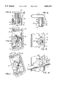
- FIG. 1 is an isometric view showing two side-by-side seating assemblies constructed according to the invention
- FIG. 2 is a side elevation view of one of the seating assemblies of FIG. 1;
- FIG. 3 is a partial exploded isometric view of one of the seating assemblies of FIG. 1, showing the manner in which the seat is mounted between the frame members;
- FIG. 4 is a partial exploded isometric view of one of the seating assemblies of FIG. 1, showing the manner in which the back is mounted between the frame members;
- FIG. 5 is a partial side elevation view showing the seat back, with a portion broken away to reveal the interconnection of the seat back with the back mounting mechanism;
- FIG. 6 is a partial sectional view taken along line 6--6 of FIG. 5;
- FIG. 7 is a partial side elevation view showing the seat, with a portion broken away to reveal the interconnection of the seat with the seat mounting mechanism;
- FIG. 8 is a partial section view taken along line 8--8 of FIG. 7;
- FIG. 9 is a partial section view taken along line 9--9 of FIG. 6, showing the back mounting mechanism
- FIG. 10 is a partial side elevation view of the back mounting mechanism of FIG. 9, showing the back pivoted to its upright, storage position;
- FIG. 11 is a view similar to FIG. 10, showing the back pivoted to its rearwardmost position
- FIG. 12 is a partial top plan view of the seat mounting mechanism somewhat similar to FIG. 8;
- FIG. 13 is a side elevation view of the seat mounting mechanism of FIG. 12, illustrating the stop member
- FIG. 14 is a view similar to FIG. 13, showing the seat pivot housing as mounted to the seat mounting mechanism of FIG. 13, with the seat shown pivoted to its forwardmost position;
- FIG. 15 is a partial elevation view showing one of the frame assemblies for use in seating assemblies constructed according to the invention.
- FIG. 1 illustrates a pair of side-by-side seating assemblies 20, 22.
- Seating assemblies 20, 22 are of the type commonly referred to as auditorium seating.
- a series of seating assemblies such as 20, 22 are positioned side-by-side to form a row, and a series of such rows are installed in a room such as an auditorium, theater or hall. Adjacent rows are separated by an aisle.
- seating assembly 20 for a detailed explanation of its construction and operation. It is understood, however, that seating assembly 22 and additional seating assemblies constructed in a row along with seating assemblies 20, 22, are constructed substantially identically to seating assembly 20 and operate in the same manner as seating assembly 20.
- Seating assembly 20 generally consists of a seat 24 and a back 26 mounted between a frame assembly 28 and a frame assembly 30.
- seating assembly 22 generally consists of a seat 32 and a back 34 mounted between frame assembly 30 and a frame assembly 35. Additional seating assemblies are interconnected with subsequent frame assemblies such as 28, 30 and 35, to form a row of seating in which each frame assembly, except the end frame assemblies such as 20, supports the seat and back of adjacent seating assemblies.
- frame assemblies 28, 30 each include upright frame member 36, 37, respectively.
- Each of upright members 36, 37 has a foot plate, shown at 38, 39, respectively, mounted at its lower end.
- foot plates 38, 39 are mounted to a floor, shown at 40, by means of a pair of screws, bolts or other threaded fasteners, shown at 42, engaged with anchors (not shown) mounted to floor 40.
- anchors not shown mounted to floor 40.
- Frame members 36, 37 terminate in an upper end
- frame assemblies 28, 30 further include rearwardly and downwardly extending upper support members 44, 45 mounted to the upper ends of frame members 36, 37, respectively.
- Each of upper support members 44, 45 terminates in an outer end spaced rearwardly from its respective frame member 36, 37 with the inner end of support members 44, 45 mounted to the upper ends of frame members 36, 37, respectively, in any satisfactory manner, such as by welding or the like.
- Frame members 36, 37 and 44, 45 as illustrated, are in the form of flattened tubular members. However, it is understood that any satisfactory structural member could be employed in place of the flattened tubular sections illustrated.
- Frame assembly 35 as well as subsequent frame assemblies to which additional seating is mounted, are constructed substantially identically to frame assemblies 28, 30 as shown and described.
- frame assemblies 28, 30 could also be satisfactorily mounted in any other manner, such as a riser or pedestal mount or mounted to a transverse beam or bar.
- seat 24 is mounted between upright frame members 36, 37 below the upper ends of upright frame members 36, 37, for pivoting movement between a storage position, shown in solid lines in FIG. 2, and an occupied position as shown in phantom in FIG. 2.
- back 26 is mounted for pivoting movement between upper support members 44, 45 toward the outer ends of the upper support members, for pivoting movement between a storage position as shown in solid lines in FIG. 2 and an occupied position as shown in phantom in FIG. 2.
- FIG. 3 illustrates mounting of seat 24 between upright frame members 36, 37 of frame assemblies 28, 30, respectively.
- a seat mounting mechanism shown generally at 46, is mounted to upright frame member 36 of frame assembly 28, and a mirror-image seat mounting mechanism 48 is mounted to upright frame member 37 of frame assembly 30.
- Seat 24 includes structure, which will later be described in detail, disposed along its lower side edges defining a pair of sockets, shown generally at 50, 52.
- a bezel 54 is mounted to the underside of seat 24, and includes an arcuate central portion 56 adapted for positioning along the side of seat 24 to enclose seat mounting mechanism 48.
- a bracket 58 is mounted to the underside of 52 such that its arcuate central portion 60 is positioned along the opposite side of seat 24 to enclose seat mounting mechanism 46.
- seat mounting mechanism 48 includes a hexagonal shaft 62 mounted to upright frame member 37, and extending therefrom in a direction substantially perpendicular to the longitudinal axis of frame member 37.
- a spacer 63 having a hexagonal passage within which shaft 62 is received, is mounted to shaft 62 adjacent the surface of upright frame member 37 from which shaft 62 extends.
- a bushing 64 defining an arcuate outer surface 66, is mounted to shaft 62 by means of a hexagonal passage formed in bushing 64 within which shaft 62 is received. In this manner, bushing 64 is non-rotatable relative to shaft 62.
- stop member 68 is mounted to shaft 62 outwardly of bushing 64.
- Stop member 68 is mounted to shaft 62 in a manner similar to that of bushing 64, in that a hexagonal passage is formed in stop member 68 within which shaft 62 is received, to non-rotatably mount stop member 68 to shaft 62.
- a snap ring 70 is engaged within a circumferential groove formed in shaft 62 outwardly of stop member 68, for retaining stop member 68 and bushing 64 in position on shaft 62.
- seat mounting mechanism 46 is substantially identical to seat mounting mechanism 48 as shown in FIG. 8 and described above, with seat mounting mechanism 46 being a mirror-image of seat mounting mechanism 48.
- a seat pivot housing 80 is located within the interior of seat 24.
- Seat pivot housing 80 is secured to a seat frame assembly, portions of which are shown at 81 in FIG. 7.
- Seat pivot housing 80 includes a pair of angled walls 82, 84, a side wall 86, a partial side wall 88 and an arcuate lip 90 located at the end of partial side wall 88.
- Arcuate lip 90 defines socket 52 (FIG. 3) within which bushing 64 is received to provide pivoting movement of seat 24.
- Seat pivot housing 80 further includes a pair of outer walls 92, 93 separated by a gap.
- seat 24 To pivotably mount seat 24 to frame members 37, seat 24 is moved rearwardly toward seat mounting mechanism 48 until the socket defined by lip 90 engages bushing 64. Simultaneously, stop member 68 is received within the interior of seat pivot housing 80 defined by wall 82-88. During rearward movement of seat 24, bushing 64 and stop member 68 pass through the gap located between outer walls 92, 93 of seat pivot housing 80.
- a plate 94 is then mounted to the frame of seat 24 to capture bushing 64 between arcuate lip 90 and plate 94. Threaded fasteners, such as screws 95, are employed to extend through openings formed in plate 94 and in bracket 54 to mount plate 72 and bracket 54 to the underside of seat 24.
- seat mounting mechanism 46 is substantially identical to seat mounting mechanism 48, being a mirror-image thereof.
- a plate 97 and screws 98 are employed to mount bracket 58 to the underside of seat 24 and to capture the bushing of seat mounting assembly 46 within socket 50 defined by the seat pivot housing on the side of seat 24 opposite seat pivot housing 80.
- the shafts, such as 62, of seat mounting mechanisms 46 and 48 extend coaxially, and define the axis about which seat 24 is pivotably mounted to frame members 36, 37 through the cooperating action of sockets 50, 52 and the arcuate outer surfaces, such as 66, of the bushings, such as 64, associated with seat mounting mechanisms 46, 48.
- seat 24 is easily mountable to seat mounting assemblies 46, 48 simply by installing plates 94, 97 using fasteners 95, 98, respectively. In a similar manner, then, seat 24 can be easily removed from seat mounting assemblies 46, 48 simply by removing plates 94, 97, respectively and lifting seat 24 off of seat mounting assemblies 46, 48. With this arrangement, it is possible to quickly and easily remove seat 24 and replace it with a replacement seat 24.
- stop member 68 is a cam-shaped member defining a pair of stop surfaces 99, 100, with a rubber bumper 101 being mounted to stop surface 100.
- a stop pin shown in FIGS. 7 and 8 at 102, extends between walls 86 and 88 of seat pivot housing 80, and is disposed adjacent stop surface 99. Stop pin 102 moves along with seat 24 as seat 24 is moved between it storage and occupied positions, with stop surface 99 defining the range of downward movement of seat 24. Pin 102 is movable between its solid line position as shown in FIG. 7, in which seat 24 is positioned vertically, and its phantom line position shown in FIG. 7, in which seat 24 is in its full-down occupied position in which pin 102 engages stop surface 99.
- a counterweight shown at 104, is mounted in the internal rear portion of seat 24.
- Counterweight 104 functions to bias seat 24 toward its vertical storage position when seat 24 is unoccupied, in a manner as is known in the art.
- Bumper 101 engages plate 94 when seat 24 returns to its storage position, to silence and cushion the impact of plate 94 with stop surface 100.
- FIGS. 12-14 illustrate seat mounting assembly 48, stop member 68, bumper 101 and seat pivot housing 80 in greater detail.
- FIG. 14 shows the position of seat pivot housing 80 when seat 24 is in its full-down occupied position.
- back 26 includes a reinforced back panel 108 which defines a pair of rectangular recesses 110, 112 located on opposite sides of back 26.
- Back panel 108 further includes a lip 114 from which a series of pins 116 extend downwardly.
- a lower curved surface 118 extends across back panel 108 at its lower end.
- a back mounting assembly 120 is mounted to upper support member 45 of frame assembly 30, and a similar back mounting assembly 122 is mounted to upper support member 44 of frame assembly 28.
- the details of construction of back mounting assemblies 120, 122 will subsequently be described.
- An additional back mounting assembly 123 is shown mounted to upper frame member 44. This construction is employed when frame assembly 28 is installed in the interior of a row of seating, and not at an end of the row as shown in FIG. 1.
- Back mounting assemblies 120, 122 are received within rectangular recesses 110, 112 formed in back panel 108 of back 26. Threaded fasteners, such as bolts 124, are employed to mount back 26, through back panel 108, to back mounting assemblies 120, 122. With back 26 mounted to back mounting assemblies 120, 122, a back cover 126 is mounted to back panel 108 to enclose the rear of back panel 108 and the rear of back mounting assemblies 120, 122. Back cover 126 includes a series of tabs 128, with each tab 128 having an opening within which one of pins 116 is received. A pair of threaded fasteners, such as screws 130, mount the lower end of back cover 126 to curved lower surface 118 of back panel 108.
- back 26 With the mounting arrangement for back 26 as shown and described, installation and removal of back 26 to and from back mounting assemblies 120, 122 is simply and easily accomplished by installation and removal, respectively of screws 130, back panel 126 and screws 124. In this manner, back 26 can easily be removed and replaced with a replacement back 26, if desired.
- FIGS. 5 and 6 illustrate the construction of back mounting assembly 120 in detail. It is understood that back mounting assembly 122 is constructed substantially identically to back mounting assembly 120, being a mirror-image thereof.
- back mounting assembly 120 consists of a housing defining a vertical outer wall 132, upper and lower side walls 134, 136, and front and back side walls 138, 140. Walls 132-140 cooperate to define a back pivot housing 141. Pivot housing 141 so defined by walls 132-140 is mounted to back panel 108 by interconnection of bolts 124 with upper and lower side walls 134, 136, respectively.
- An opening 142 is formed in the lower portion of vertical outer wall 132, and an opening 144 is formed in the upper portion of vertical outer wall 132.
- a resilient bumper member 146 is mounted within the interior of pivot housing 141. The forward end of bumper 146 overlaps the rearward portion of opening 142.
- housing 141 can be employed in a back mounting mechanism located on either side of back 20.
- a pivot shaft 148 is mounted to upper support member 45 such as by welding or the like.
- a stop shaft 150 is mounted to upper support member 45 such as by welding or the like. Shafts 148, 150 are substantially perpendicular to the plane in which upper support member 45 lies.
- Stop shaft 150 extends through opening 142 formed in the lower portion of vertical outer wall 132 of seat pivot housing 141.
- a tubular barrel 152 is mounted to vertical wall 132 of seat pivot housing 141.
- Barrel 152 includes an axial passage within which shaft 148 is received, in order to pivotably mount seat pivot housing 141 to upper support member 45.
- a sleeve 154 is mounted to the outer end of shaft 148 within the interior of seat pivot housing 141, and a cup-shaped bushing 156 is mounted to shaft 148 adjacent the outer end of sleeve 154.
- a snap ring 158 is mounted within a circumferential groove formed toward the outer end of shaft 148, to secure bushing 156 and sleeve 154, and thereby seat pivot housing 141, to shaft 148.
- a torsion spring, shown generally at 160, is mounted about sleeve 154 within the interior of seat pivot housing 141.
- Torsion spring 160 defines a pair of legs 162, 164.
- Leg 162 bears against the inner surface of vertical side wall 138 of seat pivot housing 141, and leg 164 bears against stop shaft 150.
- seat mounting assembly 120 The above-described components of seat mounting assembly 120 are illustrated in greater detail in FIGS. 9-11, and reference is made thereto for a description of the operation of seat mounting mechanism 120.
- torsion spring 160 functions to bias seat 24 toward its upright, vertical storage position, as shown in FIG. 10.
- legs 162, 164 of torsion spring 160 function to move back 24 to a position in which stop shaft 150 is engaged with the forward edge of lower opening 142 formed in vertical housing wall 132.
- the person's back engages back 26 to move back 26 away from its storage position, i.e. moving back 26 away from its vertical position according to the position of the sitter's back.
- Back 26 thus articulates to whatever position is desired by the sitter.
- FIG. 11 illustrates the rearwardmost position of back 26.
- the forward surface of resilient bumper 146 is engaged with stop shaft 150 which remains stationary on upper support member 45.
- the resiliency of bumper 146 prevents the sitter from experiencing a sudden stop when back 26 is pivoted rearwardly the full extent of its range of motion.
- back 26 pivots about pivot shaft 148 to adjust to the position of the sitter's back, to provide a high degree of comfort and support for the sitter.
- opening 142 and bumper 146 are arranged relative to stop shaft 150 so as to provide a range of motion of approximately 30°.
- torsion spring 160 again functions to return back 26 to its FIG. 10 position, in which back 26 is upright and vertical.
- This feature of the invention in combination with movement of seat 24 to its vertical storage position, allows seating assembly 20 to attain an unfolded depth, shown at W in FIG. 2, of approximately thirteen inches. This depth is extremely narrow in comparison to prior art seating assemblies which typically provide an angled back.
- the aisle space between adjacent rows of seating is typically dictated by local fire regulations, and is measured between the forwardmost point of the seat in one row and the rearwardmost point of the seat in the adjacent forward row.
- an arm cap assembly shown generally at 170, is mounted to each frame assembly, such as frame assembly 28 as illustrated.
- Each arm cap assembly 170 includes an arm cap support 172 and a cap member 174 mounted to cap support 172.
- Cap support 172 defines a downwardly facing opening or socket which, when viewed in bottom plan, corresponds in shape to the upper plan of frame assembly 28 as defined by the upper end of upright frame member 36 and rearwardly extending support member 44.
- Arm cap support 172 includes a side wall 176 which defines the opening or socket within which the upper ends of support member 44 and upright frame member 36 are received, in combination with an upper wall 178.
- Arm cap support 172 further includes a cap mounting base 180 extending upwardly from upper wall 178.
- Cap member 174 is mounted to base 180 by means of threaded fasteners extending upwardly through the side portions of base 180 and into the underside of cap member 174.
- Cap member 174 may be constructed of an injection molded plastic material as shown, either alone or covered with a pad and upholstered, or alternatively may be constructed of a wood material.
- Arm cap support 172 is employed to mount cap member 174 constructed from any type of material. Arm cap support 172 is mounted to the upper end of upright frame member 36, through side wall 176, by a pin extending transversely through an opening 182 extending through the upper end of frame member 36, and to the upper end of upper support member 44 by a pin (not shown) extending through openings 184 formed in upper support member 44.
- arm cap assembly 170 can be removed in its entirety by removing the pins extending through openings 182, 184 in order to install a replacement arm cap assembly 170.
- arm cap 174 itself can be removed from arm cap support 172 while arm cap 172 remains in place, in order to install a replacement arm cap 174.
- the compact, trim lines provided by the seating assembly of the invention provide a distinct and aesthetically appealing appearance in auditorium seating.
Abstract
Description
Claims (8)
Priority Applications (1)
| Application Number | Priority Date | Filing Date | Title |
|---|---|---|---|
| US08/335,246 US5601335A (en) | 1992-10-13 | 1994-11-07 | Auditorium seating system |
Applications Claiming Priority (2)
| Application Number | Priority Date | Filing Date | Title |
|---|---|---|---|
| US07/959,980 US5393120A (en) | 1992-10-13 | 1992-10-13 | Auditorium seating system |
| US08/335,246 US5601335A (en) | 1992-10-13 | 1994-11-07 | Auditorium seating system |
Related Parent Applications (1)
| Application Number | Title | Priority Date | Filing Date |
|---|---|---|---|
| US07/959,980 Continuation US5393120A (en) | 1992-10-13 | 1992-10-13 | Auditorium seating system |
Publications (1)
| Publication Number | Publication Date |
|---|---|
| US5601335A true US5601335A (en) | 1997-02-11 |
Family
ID=25502648
Family Applications (2)
| Application Number | Title | Priority Date | Filing Date |
|---|---|---|---|
| US07/959,980 Expired - Lifetime US5393120A (en) | 1992-10-13 | 1992-10-13 | Auditorium seating system |
| US08/335,246 Expired - Lifetime US5601335A (en) | 1992-10-13 | 1994-11-07 | Auditorium seating system |
Family Applications Before (1)
| Application Number | Title | Priority Date | Filing Date |
|---|---|---|---|
| US07/959,980 Expired - Lifetime US5393120A (en) | 1992-10-13 | 1992-10-13 | Auditorium seating system |
Country Status (2)
| Country | Link |
|---|---|
| US (2) | US5393120A (en) |
| CA (1) | CA2099165C (en) |
Cited By (12)
| Publication number | Priority date | Publication date | Assignee | Title |
|---|---|---|---|---|
| US6523900B1 (en) | 2000-09-01 | 2003-02-25 | Irwin Seating Company | Chair seat |
| US20030102703A1 (en) * | 2000-08-28 | 2003-06-05 | Alex Tenenboym | Theater seat assembly |
| US6582020B1 (en) | 2000-08-28 | 2003-06-24 | Greystone International, Inc. | Theater seat assembly |
| US6672669B2 (en) | 2001-04-30 | 2004-01-06 | First Source Furniture Group Llc | Swingable chair back with top pivot |
| US6719370B2 (en) * | 2001-09-11 | 2004-04-13 | Viscount Plastics (Nsw) Ltd. | Stadium seat |
| US6899385B2 (en) | 2003-08-29 | 2005-05-31 | Global Total Office, An Ontario Limited Partnership Having Global Upholstery Co. Inc. As Its General Partner | Auditorium seating |
| US20060103206A1 (en) * | 2004-06-12 | 2006-05-18 | Stewart Robert L | Seating unit |
| US20110187170A1 (en) * | 2010-02-03 | 2011-08-04 | Mei Chuen Lin | Seat self-lifting device for portable chair |
| US20120046147A1 (en) * | 2010-08-17 | 2012-02-23 | Precor Incorporated | Seat back mounting system |
| WO2013036514A1 (en) * | 2011-09-06 | 2013-03-14 | Series International Llc | Hinge mechanism with non-cylindrical pin |
| US8714651B2 (en) * | 2007-12-28 | 2014-05-06 | Terry Cassaday | Rotatable armrest |
| US11712118B2 (en) | 2018-11-15 | 2023-08-01 | Series International, Llc | Seat pivot bracket and beam seating system |
Families Citing this family (15)
| Publication number | Priority date | Publication date | Assignee | Title |
|---|---|---|---|---|
| US5393120A (en) * | 1992-10-13 | 1995-02-28 | Krueger International, Inc. | Auditorium seating system |
| GB2309379A (en) * | 1996-01-23 | 1997-07-30 | Robert John Hooper | Tipping seat mechanism |
| JP3321727B2 (en) * | 1996-08-02 | 2002-09-09 | 株式会社コトブキ | Chair seat rotation mechanism |
| US5899531A (en) * | 1996-08-20 | 1999-05-04 | Krueger International, Inc. | Stationarily-mounted seating structure |
| GB2354704A (en) * | 1999-09-30 | 2001-04-04 | Audience Systems Ltd | Tip-seat chair |
| WO2002007565A2 (en) * | 2000-07-21 | 2002-01-31 | American Seating Company | Auditorium chair |
| US6722735B2 (en) * | 2001-04-16 | 2004-04-20 | Ditto Sales, Inc. | Chair with synchronously moving seat and seat back |
| US20030154660A1 (en) * | 2001-10-19 | 2003-08-21 | Michael Berkowicz | Connector for arranging modular seats in a non-linear array |
| US7240963B2 (en) * | 2005-02-22 | 2007-07-10 | Stanley Larry S | Hand rail assembly incorporating articulating seats |
| US20100244515A1 (en) * | 2009-03-31 | 2010-09-30 | Dragomir Ivicevic | Reclining Chair |
| CN101779868B (en) * | 2010-04-02 | 2012-03-21 | 丰岳 | Chair counterbalanced by mortar |
| US9504326B1 (en) | 2012-04-10 | 2016-11-29 | Humanscale Corporation | Reclining chair |
| EP3603453A1 (en) | 2015-05-14 | 2020-02-05 | VIP Cinema LLC | Motor driven sloped floor recline mechanism for a theater seat |
| JP2018514290A (en) | 2015-05-14 | 2018-06-07 | ブイアイピー シネマ エルエルシー | Dual motion inclined floor reclining mechanism for theater |
| USD808676S1 (en) * | 2016-09-21 | 2018-01-30 | 4Topps, LLC | Riser mounted row seats |
Citations (29)
| Publication number | Priority date | Publication date | Assignee | Title |
|---|---|---|---|---|
| US444101A (en) * | 1891-01-06 | Folding chair | ||
| US1435741A (en) * | 1922-09-13 | 1922-11-14 | Sadler Alfred George | Theater chair |
| US1437630A (en) * | 1920-10-21 | 1922-12-05 | Zimmerli Charles | Stool |
| GB235586A (en) * | 1924-06-12 | 1926-03-11 | Willy Merten | Improvements in or relating to folding seats |
| US2124893A (en) * | 1936-09-15 | 1938-07-26 | Peppas Sam | Chair |
| DE669162C (en) * | 1937-07-22 | 1938-12-17 | Ernst Wolf & Cie | Suspension arranged on the pivot pin of a folding seat of single or row chairs |
| US2336128A (en) * | 1940-09-25 | 1943-12-07 | Peabody Company | Chair |
| US2560925A (en) * | 1950-04-24 | 1951-07-17 | Clayton W Brown | Adjustable head rest |
| US2582599A (en) * | 1947-08-06 | 1952-01-15 | American Seating Co | Seat mounting for theater chairs or the like |
| US2705526A (en) * | 1948-08-30 | 1955-04-05 | American Seating Co | Chair with self-folding seat |
| US2796920A (en) * | 1955-02-01 | 1957-06-25 | Gen Tire & Rubber Co | Chair back support |
| US2913039A (en) * | 1956-01-18 | 1959-11-17 | Mauser Kommanditgesellschaft F | Seat mounting device |
| US3163409A (en) * | 1961-08-25 | 1964-12-29 | Peter R Running | Torsion bar seat suspension |
| US3194601A (en) * | 1964-06-08 | 1965-07-13 | American Seating Co | Audience chairs |
| US3272555A (en) * | 1964-11-12 | 1966-09-13 | American Seating Co | Adjustable back lounge chair |
| US3572826A (en) * | 1968-07-05 | 1971-03-30 | American Desk Mfg Co | Push back seat chair |
| US3638998A (en) * | 1969-08-28 | 1972-02-01 | Paul G Anderson | Stadium chair with folding seat |
| US3813149A (en) * | 1971-12-23 | 1974-05-28 | Lawrence Brothers | Pivotal mounting device for stadium seats and the like |
| US3820845A (en) * | 1971-10-05 | 1974-06-28 | Expo Nord Ab | Sitting furniture |
| US4049315A (en) * | 1976-12-13 | 1977-09-20 | Jacobson John D | Chair having independent seat and back |
| US4189876A (en) * | 1978-08-07 | 1980-02-26 | American Seating Company | Beam-mounted folding chairs |
| US4211450A (en) * | 1979-04-05 | 1980-07-08 | Hussey Manufacturing Company, Inc. | Release mechanism for rows of collapsible seats |
| US4400031A (en) * | 1981-03-12 | 1983-08-23 | Virco Mfg. Corporation | Interlocking chair |
| US4458943A (en) * | 1981-10-26 | 1984-07-10 | Kay Springs, Incorporated | Spring seat |
| US4502731A (en) * | 1981-06-01 | 1985-03-05 | Snider Robert A | Seat frame |
| US4575150A (en) * | 1984-04-09 | 1986-03-11 | Simodow Manufacturing Ltd. | Suspension arrangement for a tilting chair |
| US4756575A (en) * | 1987-05-11 | 1988-07-12 | Faultless-Doerner Manufacturing Inc. | Frame assembly for a chair |
| US4861108A (en) * | 1988-06-07 | 1989-08-29 | American Seating Company | Auditorium seat |
| US5393120A (en) * | 1992-10-13 | 1995-02-28 | Krueger International, Inc. | Auditorium seating system |
-
1992
- 1992-10-13 US US07/959,980 patent/US5393120A/en not_active Expired - Lifetime
-
1993
- 1993-06-25 CA CA002099165A patent/CA2099165C/en not_active Expired - Lifetime
-
1994
- 1994-11-07 US US08/335,246 patent/US5601335A/en not_active Expired - Lifetime
Patent Citations (29)
| Publication number | Priority date | Publication date | Assignee | Title |
|---|---|---|---|---|
| US444101A (en) * | 1891-01-06 | Folding chair | ||
| US1437630A (en) * | 1920-10-21 | 1922-12-05 | Zimmerli Charles | Stool |
| US1435741A (en) * | 1922-09-13 | 1922-11-14 | Sadler Alfred George | Theater chair |
| GB235586A (en) * | 1924-06-12 | 1926-03-11 | Willy Merten | Improvements in or relating to folding seats |
| US2124893A (en) * | 1936-09-15 | 1938-07-26 | Peppas Sam | Chair |
| DE669162C (en) * | 1937-07-22 | 1938-12-17 | Ernst Wolf & Cie | Suspension arranged on the pivot pin of a folding seat of single or row chairs |
| US2336128A (en) * | 1940-09-25 | 1943-12-07 | Peabody Company | Chair |
| US2582599A (en) * | 1947-08-06 | 1952-01-15 | American Seating Co | Seat mounting for theater chairs or the like |
| US2705526A (en) * | 1948-08-30 | 1955-04-05 | American Seating Co | Chair with self-folding seat |
| US2560925A (en) * | 1950-04-24 | 1951-07-17 | Clayton W Brown | Adjustable head rest |
| US2796920A (en) * | 1955-02-01 | 1957-06-25 | Gen Tire & Rubber Co | Chair back support |
| US2913039A (en) * | 1956-01-18 | 1959-11-17 | Mauser Kommanditgesellschaft F | Seat mounting device |
| US3163409A (en) * | 1961-08-25 | 1964-12-29 | Peter R Running | Torsion bar seat suspension |
| US3194601A (en) * | 1964-06-08 | 1965-07-13 | American Seating Co | Audience chairs |
| US3272555A (en) * | 1964-11-12 | 1966-09-13 | American Seating Co | Adjustable back lounge chair |
| US3572826A (en) * | 1968-07-05 | 1971-03-30 | American Desk Mfg Co | Push back seat chair |
| US3638998A (en) * | 1969-08-28 | 1972-02-01 | Paul G Anderson | Stadium chair with folding seat |
| US3820845A (en) * | 1971-10-05 | 1974-06-28 | Expo Nord Ab | Sitting furniture |
| US3813149A (en) * | 1971-12-23 | 1974-05-28 | Lawrence Brothers | Pivotal mounting device for stadium seats and the like |
| US4049315A (en) * | 1976-12-13 | 1977-09-20 | Jacobson John D | Chair having independent seat and back |
| US4189876A (en) * | 1978-08-07 | 1980-02-26 | American Seating Company | Beam-mounted folding chairs |
| US4211450A (en) * | 1979-04-05 | 1980-07-08 | Hussey Manufacturing Company, Inc. | Release mechanism for rows of collapsible seats |
| US4400031A (en) * | 1981-03-12 | 1983-08-23 | Virco Mfg. Corporation | Interlocking chair |
| US4502731A (en) * | 1981-06-01 | 1985-03-05 | Snider Robert A | Seat frame |
| US4458943A (en) * | 1981-10-26 | 1984-07-10 | Kay Springs, Incorporated | Spring seat |
| US4575150A (en) * | 1984-04-09 | 1986-03-11 | Simodow Manufacturing Ltd. | Suspension arrangement for a tilting chair |
| US4756575A (en) * | 1987-05-11 | 1988-07-12 | Faultless-Doerner Manufacturing Inc. | Frame assembly for a chair |
| US4861108A (en) * | 1988-06-07 | 1989-08-29 | American Seating Company | Auditorium seat |
| US5393120A (en) * | 1992-10-13 | 1995-02-28 | Krueger International, Inc. | Auditorium seating system |
Cited By (19)
| Publication number | Priority date | Publication date | Assignee | Title |
|---|---|---|---|---|
| US20030102703A1 (en) * | 2000-08-28 | 2003-06-05 | Alex Tenenboym | Theater seat assembly |
| US6582020B1 (en) | 2000-08-28 | 2003-06-24 | Greystone International, Inc. | Theater seat assembly |
| US6612652B1 (en) | 2000-08-28 | 2003-09-02 | Greystone International, Inc. | Theater seat assembly |
| US6523900B1 (en) | 2000-09-01 | 2003-02-25 | Irwin Seating Company | Chair seat |
| US6652030B2 (en) | 2000-09-01 | 2003-11-25 | Irwin Seating Company | Chair seat |
| US6672669B2 (en) | 2001-04-30 | 2004-01-06 | First Source Furniture Group Llc | Swingable chair back with top pivot |
| US6719370B2 (en) * | 2001-09-11 | 2004-04-13 | Viscount Plastics (Nsw) Ltd. | Stadium seat |
| US20050168017A1 (en) * | 2003-08-29 | 2005-08-04 | Vaclav Pernicka | Auditorium seating |
| US6899385B2 (en) | 2003-08-29 | 2005-05-31 | Global Total Office, An Ontario Limited Partnership Having Global Upholstery Co. Inc. As Its General Partner | Auditorium seating |
| US20060103206A1 (en) * | 2004-06-12 | 2006-05-18 | Stewart Robert L | Seating unit |
| US7325873B2 (en) | 2004-06-12 | 2008-02-05 | Steelcase Inc. | Seating unit |
| US8714651B2 (en) * | 2007-12-28 | 2014-05-06 | Terry Cassaday | Rotatable armrest |
| US20110187170A1 (en) * | 2010-02-03 | 2011-08-04 | Mei Chuen Lin | Seat self-lifting device for portable chair |
| US8109564B2 (en) * | 2010-02-03 | 2012-02-07 | Mei Chuen Lin | Seat self-lifting device for portable chair |
| US20120046147A1 (en) * | 2010-08-17 | 2012-02-23 | Precor Incorporated | Seat back mounting system |
| US8672814B2 (en) * | 2010-08-17 | 2014-03-18 | Precor Incorporated | Seat back mounting system |
| WO2013036514A1 (en) * | 2011-09-06 | 2013-03-14 | Series International Llc | Hinge mechanism with non-cylindrical pin |
| US9295334B2 (en) | 2011-09-06 | 2016-03-29 | Series International, Llc | Hinge mechanism with non-cylindrical pin |
| US11712118B2 (en) | 2018-11-15 | 2023-08-01 | Series International, Llc | Seat pivot bracket and beam seating system |
Also Published As
| Publication number | Publication date |
|---|---|
| CA2099165C (en) | 2000-03-14 |
| US5393120A (en) | 1995-02-28 |
| CA2099165A1 (en) | 1994-04-14 |
Similar Documents
| Publication | Publication Date | Title |
|---|---|---|
| US5601335A (en) | Auditorium seating system | |
| US4189876A (en) | Beam-mounted folding chairs | |
| US5106157A (en) | Chair height and tilt adjustment mechanisms | |
| US5938284A (en) | Seat bolster adjustment assembly | |
| US6142559A (en) | Seating product | |
| CA1219516A (en) | Seating unit with front flex area | |
| US5435622A (en) | Swivel recliner/rocker chair having preloaded base assembly | |
| US20200305610A1 (en) | Housing and tilt mechanism for a chair and a chair, in particular an office chair | |
| US5899531A (en) | Stationarily-mounted seating structure | |
| US4789203A (en) | Chair with movable seat and backrest | |
| US3863982A (en) | Tilt-swivel mechanism for a chair | |
| US20020158496A1 (en) | Swingable chair back with top pivot | |
| US6061891A (en) | Method of assembling an adjustable mechanism for rocker-recliner | |
| JPS5810009A (en) | Seat attaching part enabling forward inclination of seat | |
| US4466665A (en) | Chair having adjsutable, cantilevered lumbar-supporting arm | |
| EP0941679B1 (en) | Rocking and gliding mechanism | |
| US6161897A (en) | Chair construction | |
| CA1156136A (en) | Mounting device for a chair seat | |
| US20020113474A1 (en) | Chair with a folding backrest and a hinge therefor | |
| US5857744A (en) | Swivel base lockout assembly | |
| GB2215195A (en) | Arrangement for protecting seat operation lever against seat belt in vehicle seat | |
| JP2877715B2 (en) | Vehicle stool footrest device | |
| KR200147148Y1 (en) | Armrest for a car | |
| US4435860A (en) | Spring suspension for sofa-bed | |
| JPH0636780Y2 (en) | sofa |
Legal Events
| Date | Code | Title | Description |
|---|---|---|---|
| STCF | Information on status: patent grant |
Free format text: PATENTED CASE |
|
| FPAY | Fee payment |
Year of fee payment: 4 |
|
| FPAY | Fee payment |
Year of fee payment: 8 |
|
| AS | Assignment |
Owner name: KRUEGER INTERNATIONAL, INC., WISCONSIN Free format text: ASSIGNMENT OF ASSIGNORS INTEREST;ASSIGNORS:WOODS, DAVID C.;KOPROWSKI, RICHARD A.;REEL/FRAME:019181/0975;SIGNING DATES FROM 19930223 TO 19930316 |
|
| FPAY | Fee payment |
Year of fee payment: 12 |
|
| AS | Assignment |
Owner name: U.S. BANK NATIONAL ASSOCIATION,MISSOURI Free format text: SECURITY AGREEMENT;ASSIGNOR:KRUEGER INTERNATIONAL, INC.;REEL/FRAME:024233/0760 Effective date: 20100407 Owner name: U.S. BANK NATIONAL ASSOCIATION, MISSOURI Free format text: SECURITY AGREEMENT;ASSIGNOR:KRUEGER INTERNATIONAL, INC.;REEL/FRAME:024233/0760 Effective date: 20100407 |
|
| AS | Assignment |
Owner name: WELLS FARGO BANK, NATIONAL ASSOCIATION, AS AGENT, Free format text: SECURITY AGREEMENT;ASSIGNOR:KRUEGER INTERNATIONAL, INC.;REEL/FRAME:029580/0379 Effective date: 20121228 |