US5600727A - Determination of position - Google Patents
Determination of position Download PDFInfo
- Publication number
- US5600727A US5600727A US08/271,602 US27160294A US5600727A US 5600727 A US5600727 A US 5600727A US 27160294 A US27160294 A US 27160294A US 5600727 A US5600727 A US 5600727A
- Authority
- US
- United States
- Prior art keywords
- microphones
- sonic
- signal generators
- signals
- reference point
- Prior art date
- Legal status (The legal status is an assumption and is not a legal conclusion. Google has not performed a legal analysis and makes no representation as to the accuracy of the status listed.)
- Expired - Lifetime
Links
Images


Classifications
-
- H—ELECTRICITY
- H04—ELECTRIC COMMUNICATION TECHNIQUE
- H04R—LOUDSPEAKERS, MICROPHONES, GRAMOPHONE PICK-UPS OR LIKE ACOUSTIC ELECTROMECHANICAL TRANSDUCERS; DEAF-AID SETS; PUBLIC ADDRESS SYSTEMS
- H04R5/00—Stereophonic arrangements
- H04R5/027—Spatial or constructional arrangements of microphones, e.g. in dummy heads
-
- H—ELECTRICITY
- H04—ELECTRIC COMMUNICATION TECHNIQUE
- H04R—LOUDSPEAKERS, MICROPHONES, GRAMOPHONE PICK-UPS OR LIKE ACOUSTIC ELECTROMECHANICAL TRANSDUCERS; DEAF-AID SETS; PUBLIC ADDRESS SYSTEMS
- H04R3/00—Circuits for transducers, loudspeakers or microphones
- H04R3/005—Circuits for transducers, loudspeakers or microphones for combining the signals of two or more microphones
-
- H—ELECTRICITY
- H04—ELECTRIC COMMUNICATION TECHNIQUE
- H04S—STEREOPHONIC SYSTEMS
- H04S3/00—Systems employing more than two channels, e.g. quadraphonic
- H04S3/02—Systems employing more than two channels, e.g. quadraphonic of the matrix type, i.e. in which input signals are combined algebraically, e.g. after having been phase shifted with respect to each other
Definitions
- the present invention relates to a method and apparatus for determination of position and has particular, although not exclusive, relevance to use in so-called dummy-head recording techniques.
- a dummy-head recording system is disclosed in U.S. Pat. No. 4,119,798.
- a dummy-head having microphones mounted in the ear canals thereof is used for multi-channel stereophonic sound recording.
- An acoustic cross-talk cancellation circuit is arranged to receive the microphone signals thereby to provide a binaural effect when reproduced through loudspeakers.
- this position may be measured, such as using polar coordinates by utilising a theodolite and an optical range finder.
- Cartesian coordinates of the remote microphones and dummy head could be measured with respect to the boundaries of the room in which the recording is to take place, and then the azimuth angle, depression/elevation angle and the time-of-flight distance between the dummy-head and each remote microphone could be calculated.
- remote microphones may be physically difficult to access for measurement purposes due to being suspended several meters from the ground above an orchestra, for example.
- a method of determining the position of a receiver relative to a given reference point comprising:
- the signals transmitted from each of the signal generators are transient pulses. Furthermore the signals may be transmitted from each of the plurality of signal generators in turn.
- an apparatus for determining the position of a receiver relative to a given reference point comprising:
- a signal receiver for receiving the transmitted signals
- a signal processor for measuring the time-of-flight of the signals from each signal generator to the receiver and geometrically determining, from the time-of-flight measurements and the position of the given reference point relative to each signal generator, the distance and angular disposition of the receiver relative to the given reference point.
- FIG. 1 illustrates schematically an autocalibration system in accordance with the present invention
- FIG. 2 shows a schematic representation of signal transmission by the right loudspeaker of the autocalibration system of FIG. 1;
- FIG. 3 shows a schematic representation of signal transmission by the left loudspeaker of the autocalibration system of FIG. 1;
- FIG. 4 illustrates schematically how circles of propagation for the fight loudspeaker are constructed
- FIG. 5 illustrates schematically how the position and angular displacement of a microphone is determined
- FIG. 6 shows a schematic representation of a second embodiment of the present invention.
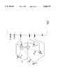
- FIG. 1 a two-dimensional autocalibration system for a multi-microphone array in accordance with the present invention is illustrated in which all microphones and loudspeakers lie in the same plane.
- Two signal generators, in this case loudspeakers 2, 4 which are physically coupled via mounting bracket 6, are fed with transient pulses via their respective drive inputs 8, 10.
- the loudspeakers 2, 4 are placed one on either side of a dummy-head 12 such that the lateral centre-line 14 through the dummy-head 12 (i.e. through both ears from one side to the other) and the loudspeakers 2, 4 lie in the same plane.
- microphones 16, 18, 20 whose positions in relation to the dummy-head 12 are to be determined are disposed in front of the head 12 and situated at unknown azimuth angles ⁇ 16 , ⁇ 18 and ⁇ 20 respectively to the centre-line 22 through the head 12 from its back to its front. Furthermore each microphone 16, 18, 20 lies at an unknown distance from the centre of the head 12 (the latter defined by the point of intersection of the two centre-lines 14 and 22); d 16 , d 18 and d 20 respectively.
- Each microphone 16, 18, 20 feeds into a respective preamplifier 24 and then into a respective high-precision analogue-to-digital (A/D) converter 26 after which the digitised signal is transferred into a local memory store 28 under the control of a signal processor 30 which communicates via control data bus 32.
- Each memory store 28 is capable of storing 200 ms of data at a rate of 44.1 kbits per second.
- the control bus 32 also drives, in parallel, a pair of buffers 34 each of which is coupled to a respective digital-to-analogue (D/A) converter 36 and thence to a power amplifier 38.
- D/A digital-to-analogue
- a signal here a transient pulse
- the signal processor 30 is generated (in known manner) by the signal processor 30 and sent to the drive input 10 of the (right) loudspeaker 4 via the control bus 32 and the corresponding buffer 34, D/A 36 and amplifier 38.
- the outputs of all the microphones 16, 18, 20 are transferred at a constant rate into their respective memory stores 28 via their respective preamplifiers 24 and D/As 26.
- These outputs are transferred to their respective memory stores 28 only for a pre-determined period, typically 100ms (or until the stores 28 are full), thus forming a temporary, time-domain record of their activity.
- the record of activity of each microphone 16, 18, 20 held within each respective memory store 28 is inspected by the signal processor 30 via data bus 32. This allows detection of the time location of the received transient pulse transmitted by the (right) loudspeaker 4 with respect to the beginning of the record (i.e. at the instant at which the pulse was propagated). Thus the time difference between the transmission of the pulse by the loudspeaker 4 and the time of arrival of the pulse at each microphone 16, 18, 20 can be determined by the signal processor 30. These transit times are known as the time-of-flight of the transit pulse from the loudspeaker 4 to each of the microphones 16, 18, 20.
- Each transit distance d1 16 , d1 18 , d1 12 can be calculated directly from the corresponding time-of-flight measurement t l6 , t 18 , t 20 and the velocity of sound in air at room temperature and humidity ( ⁇ 343 ms -1 ) using the relationship:
- v velocity of sound in air.
- the three microphones 16, 18, 20 are located, respectively, at distances d1 16 , d1 18 , d1 20 from the loudspeaker 4, given by:
- each microphone 16, 18, 20 with respect to the dummy-head 12 can now be determined. Referring to FIG. 4, if a circle having radius d1 16 is constructed around a centre which is the loudspeaker 4, then the circumference of this circle represents the location of the wavefront, emitted from the loudspeaker 4 at a time when the microphone 16 registered it.
- the larger circle in FIG. 4, of radius d2 16 is constructed around a centre which is the loudspeaker 2.
- This circle corresponds to the "circle of propagation" from the loudspeaker 2 to the microphone 16.
- the microphone 16 must lie at the intersection of both circles, as shown. (It can be seen from FIG. 4 that, by symmetry, the microphone could also lie at 16 1 , but it is known already that all three microphones 16, 18, 20 actually lie in front of the head 12 and so this "ghost" position can readily be discounted. In any event, this "ghost” can be removed simply by use of an additional loudspeaker set away from the plane of loudspeakers 2 and 4). Similar procedures are used to locate the positions of microphones 18 and 20.
- each microphone 16, 18, 20 with respect to a given reference point.
- the given reference point is the centre of the dummy-head 12 defined by the points of intersection of the centre-lines 14 and 22.
- both the azimuth angle ⁇ 16 and distance d 16 of the microphone 16 with respect to the dummy-head as is required. It will be appreciated that, although only the azimuth angle ⁇ 16 and distance d 16 for the microphone 16 have been described, this is for clarity only, and the same trigonometrical treatment is used to find ⁇ 18 , ⁇ 20 and d 18 , d 20 as well as d1 18 , d2 18 and d1 20 , d2 20 .
- FIG. 6 the case of determination of the position of the microphone relative to a given reference point, here again the dummy-head 12, when the head 12 does not lie on the line 14 drawn between the two loudspeakers 2, 4 is illustrated.
- the separation, x, of the loudspeakers 2, 4 must be known and the position of the head 12 relative to a point, say the midway between the loudspeakers, also measured.
- the head 12 is at distance w from the midpoint, parallel to line 14 joining the loudspeakers 2, 4 and at distance y from this midpoint in a direction perpendicular to line 14.
- the distances x, w and y are known from measurements and the distances d1 16 and d2 16 have been calculated from the time-of-flight measurements.
- the distance and angular disposition of the microphone 16 relative to the head 12 may be determined from a knowledge of the time-of-flight measurements from each loudspeaker 2, 4 to the microphone and the distance measurements between the head 12 and the loudspeakers.
- transient pulses transmitted by each loudspeaker any suitable signals may be used and there is no compulsion for their transmission to be from each microphone in turn.
- transient pulses it is convenient for each microphone not to register subsequently received pulses after their first-received pulse from each loudspeaker has been registered. This obviates, for example, registration of stray reflectances from walls or the like.
- receivers could also be placed inside or around the dummy-head in the example described hereabove enabling calculation of the dummy head itself with respect to a known reference point.
Abstract
Description
d=vt
d1.sub.16 =vt.sub.16, d1.sub.18 =vt.sub.18 and d1.sub.20 =vt.sub.20.
Claims (7)
Applications Claiming Priority (2)
| Application Number | Priority Date | Filing Date | Title |
|---|---|---|---|
| GB9314822 | 1993-07-17 | ||
| GB939314822A GB9314822D0 (en) | 1993-07-17 | 1993-07-17 | Determination of position |
Publications (1)
| Publication Number | Publication Date |
|---|---|
| US5600727A true US5600727A (en) | 1997-02-04 |
Family
ID=10738983
Family Applications (1)
| Application Number | Title | Priority Date | Filing Date |
|---|---|---|---|
| US08/271,602 Expired - Lifetime US5600727A (en) | 1993-07-17 | 1994-07-07 | Determination of position |
Country Status (4)
| Country | Link |
|---|---|
| US (1) | US5600727A (en) |
| EP (1) | EP0634881B1 (en) |
| DE (1) | DE69423268T2 (en) |
| GB (1) | GB9314822D0 (en) |
Cited By (18)
| Publication number | Priority date | Publication date | Assignee | Title |
|---|---|---|---|---|
| US5901232A (en) * | 1996-09-03 | 1999-05-04 | Gibbs; John Ho | Sound system that determines the position of an external sound source and points a directional microphone/speaker towards it |
| US20020041693A1 (en) * | 1997-06-26 | 2002-04-11 | Naoshi Matsuo | Microphone array apparatus |
| US6556687B1 (en) * | 1998-02-23 | 2003-04-29 | Nec Corporation | Super-directional loudspeaker using ultrasonic wave |
| US6600824B1 (en) * | 1999-08-03 | 2003-07-29 | Fujitsu Limited | Microphone array system |
| US6748088B1 (en) * | 1998-03-23 | 2004-06-08 | Volkswagen Ag | Method and device for operating a microphone system, especially in a motor vehicle |
| US20040114772A1 (en) * | 2002-03-21 | 2004-06-17 | David Zlotnick | Method and system for transmitting and/or receiving audio signals with a desired direction |
| US20040170289A1 (en) * | 2003-02-27 | 2004-09-02 | Whan Wen Jea | Audio conference system with quality-improving features by compensating sensitivities microphones and the method thereof |
| US20040193853A1 (en) * | 2001-04-20 | 2004-09-30 | Maier Klaus D. | Program-controlled unit |
| US20040252849A1 (en) * | 1999-12-21 | 2004-12-16 | Johnston James David | Microphone array for preserving soundfield perceptual cues |
| US20050249360A1 (en) * | 2004-05-07 | 2005-11-10 | Fuji Xerox Co., Ltd. | Systems and methods for microphone localization |
| US7366308B1 (en) * | 1997-04-10 | 2008-04-29 | Beyerdynamic Gmbh & Co. Kg | Sound pickup device, specially for a voice station |
| DE102008024067A1 (en) * | 2008-05-17 | 2009-11-19 | Dr. Sibaei & Hastrich Ingenieurgesellschaft b.R. (vertretungsberechtigte Gesellschafter Dr. Ziad Sibaei, 83607 Holzkirchen und Hans Peter Hastrich, 83607 Holzkirchen) | Method for calibration of microphone array, involves receiving part of acoustic signal, emitted from sound source of calibration unit with help of calibration microphone provided in calibration unit |
| US20100177178A1 (en) * | 2009-01-14 | 2010-07-15 | Alan Alexander Burns | Participant audio enhancement system |
| US20100322035A1 (en) * | 1999-05-19 | 2010-12-23 | Rhoads Geoffrey B | Audio-Based, Location-Related Methods |
| US20110182148A1 (en) * | 2008-04-28 | 2011-07-28 | Fraunhofer-Gesellschaft Zur Foerderung Der Angewandten Forschung E.V. | Method and Apparatus for Locating at Least One Object |
| CN103916734A (en) * | 2013-12-31 | 2014-07-09 | 华为终端有限公司 | Method and terminal for processing sound signals |
| US11350229B2 (en) * | 2018-03-29 | 2022-05-31 | Cae Inc. | Method and system for determining a position of a microphone |
| US11581004B2 (en) | 2020-12-02 | 2023-02-14 | HearUnow, Inc. | Dynamic voice accentuation and reinforcement |
Families Citing this family (3)
| Publication number | Priority date | Publication date | Assignee | Title |
|---|---|---|---|---|
| US6023514A (en) * | 1997-12-22 | 2000-02-08 | Strandberg; Malcolm W. P. | System and method for factoring a merged wave field into independent components |
| NO316560B1 (en) * | 2001-02-21 | 2004-02-02 | Meditron Asa | Microphone with rangefinder |
| WO2006120499A1 (en) * | 2005-05-12 | 2006-11-16 | Nokia Corporation, | Positioning of a portable electronic device |
Citations (5)
| Publication number | Priority date | Publication date | Assignee | Title |
|---|---|---|---|---|
| US4119798A (en) * | 1975-09-04 | 1978-10-10 | Victor Company Of Japan, Limited | Binaural multi-channel stereophony |
| US4586195A (en) * | 1984-06-25 | 1986-04-29 | Siemens Corporate Research & Support, Inc. | Microphone range finder |
| US4733355A (en) * | 1986-02-10 | 1988-03-22 | Agtek Development Company, Inc. | Non-contacting range sensing and control device |
| US4796726A (en) * | 1984-05-29 | 1989-01-10 | Nissan Motor Co., Ltd. | Ultrasonic rangefinder |
| US5206838A (en) * | 1991-07-29 | 1993-04-27 | Tokimec Inc. | Ultrasonic transducer |
Family Cites Families (3)
| Publication number | Priority date | Publication date | Assignee | Title |
|---|---|---|---|---|
| GB2115150B (en) * | 1982-02-11 | 1985-06-26 | Plessey Co Plc | Sound source location system |
| JPS62108171A (en) * | 1985-11-07 | 1987-05-19 | Oki Electric Ind Co Ltd | Calibrating system for location of echo sound receiver |
| JP3232608B2 (en) * | 1991-11-25 | 2001-11-26 | ソニー株式会社 | Sound collecting device, reproducing device, sound collecting method and reproducing method, and sound signal processing device |
-
1993
- 1993-07-17 GB GB939314822A patent/GB9314822D0/en active Pending
-
1994
- 1994-07-04 EP EP94304882A patent/EP0634881B1/en not_active Expired - Lifetime
- 1994-07-04 DE DE69423268T patent/DE69423268T2/en not_active Expired - Fee Related
- 1994-07-07 US US08/271,602 patent/US5600727A/en not_active Expired - Lifetime
Patent Citations (5)
| Publication number | Priority date | Publication date | Assignee | Title |
|---|---|---|---|---|
| US4119798A (en) * | 1975-09-04 | 1978-10-10 | Victor Company Of Japan, Limited | Binaural multi-channel stereophony |
| US4796726A (en) * | 1984-05-29 | 1989-01-10 | Nissan Motor Co., Ltd. | Ultrasonic rangefinder |
| US4586195A (en) * | 1984-06-25 | 1986-04-29 | Siemens Corporate Research & Support, Inc. | Microphone range finder |
| US4733355A (en) * | 1986-02-10 | 1988-03-22 | Agtek Development Company, Inc. | Non-contacting range sensing and control device |
| US5206838A (en) * | 1991-07-29 | 1993-04-27 | Tokimec Inc. | Ultrasonic transducer |
Cited By (27)
| Publication number | Priority date | Publication date | Assignee | Title |
|---|---|---|---|---|
| US5901232A (en) * | 1996-09-03 | 1999-05-04 | Gibbs; John Ho | Sound system that determines the position of an external sound source and points a directional microphone/speaker towards it |
| US7366308B1 (en) * | 1997-04-10 | 2008-04-29 | Beyerdynamic Gmbh & Co. Kg | Sound pickup device, specially for a voice station |
| US20020041693A1 (en) * | 1997-06-26 | 2002-04-11 | Naoshi Matsuo | Microphone array apparatus |
| US7035416B2 (en) * | 1997-06-26 | 2006-04-25 | Fujitsu Limited | Microphone array apparatus |
| US6556687B1 (en) * | 1998-02-23 | 2003-04-29 | Nec Corporation | Super-directional loudspeaker using ultrasonic wave |
| US6748088B1 (en) * | 1998-03-23 | 2004-06-08 | Volkswagen Ag | Method and device for operating a microphone system, especially in a motor vehicle |
| US8122257B2 (en) | 1999-05-19 | 2012-02-21 | Digimarc Corporation | Audio-based, location-related methods |
| US20100322035A1 (en) * | 1999-05-19 | 2010-12-23 | Rhoads Geoffrey B | Audio-Based, Location-Related Methods |
| US6600824B1 (en) * | 1999-08-03 | 2003-07-29 | Fujitsu Limited | Microphone array system |
| US6845163B1 (en) * | 1999-12-21 | 2005-01-18 | At&T Corp | Microphone array for preserving soundfield perceptual cues |
| US20040252849A1 (en) * | 1999-12-21 | 2004-12-16 | Johnston James David | Microphone array for preserving soundfield perceptual cues |
| US7149315B2 (en) * | 1999-12-21 | 2006-12-12 | At&T Corp. | Microphone array for preserving soundfield perceptual cues |
| US20040193853A1 (en) * | 2001-04-20 | 2004-09-30 | Maier Klaus D. | Program-controlled unit |
| US20040114772A1 (en) * | 2002-03-21 | 2004-06-17 | David Zlotnick | Method and system for transmitting and/or receiving audio signals with a desired direction |
| US20040170289A1 (en) * | 2003-02-27 | 2004-09-02 | Whan Wen Jea | Audio conference system with quality-improving features by compensating sensitivities microphones and the method thereof |
| US7522736B2 (en) * | 2004-05-07 | 2009-04-21 | Fuji Xerox Co., Ltd. | Systems and methods for microphone localization |
| US20050249360A1 (en) * | 2004-05-07 | 2005-11-10 | Fuji Xerox Co., Ltd. | Systems and methods for microphone localization |
| US20110182148A1 (en) * | 2008-04-28 | 2011-07-28 | Fraunhofer-Gesellschaft Zur Foerderung Der Angewandten Forschung E.V. | Method and Apparatus for Locating at Least One Object |
| US8611188B2 (en) | 2008-04-28 | 2013-12-17 | Fraunhofer-Gesellschaft zur Förderung der angewandten Forschung e.V. | Method and apparatus for locating at least one object |
| DE102008024067A1 (en) * | 2008-05-17 | 2009-11-19 | Dr. Sibaei & Hastrich Ingenieurgesellschaft b.R. (vertretungsberechtigte Gesellschafter Dr. Ziad Sibaei, 83607 Holzkirchen und Hans Peter Hastrich, 83607 Holzkirchen) | Method for calibration of microphone array, involves receiving part of acoustic signal, emitted from sound source of calibration unit with help of calibration microphone provided in calibration unit |
| DE102008024067B4 (en) * | 2008-05-17 | 2013-11-14 | Dr. Sibaei & Hastrich Ingenieurgesellschaft b.R. (vertretungsberechtigte Gesellschafter Dr. Ziad Sibaei, 83607 Holzkirchen und Hans Peter Hastrich, 83607 Holzkirchen) | Arrangement and method for calibrating a microphone array |
| US20100177178A1 (en) * | 2009-01-14 | 2010-07-15 | Alan Alexander Burns | Participant audio enhancement system |
| US8154588B2 (en) * | 2009-01-14 | 2012-04-10 | Alan Alexander Burns | Participant audio enhancement system |
| CN103916734A (en) * | 2013-12-31 | 2014-07-09 | 华为终端有限公司 | Method and terminal for processing sound signals |
| CN103916734B (en) * | 2013-12-31 | 2018-12-07 | 华为终端(东莞)有限公司 | A kind of audio signal processing method and terminal |
| US11350229B2 (en) * | 2018-03-29 | 2022-05-31 | Cae Inc. | Method and system for determining a position of a microphone |
| US11581004B2 (en) | 2020-12-02 | 2023-02-14 | HearUnow, Inc. | Dynamic voice accentuation and reinforcement |
Also Published As
| Publication number | Publication date |
|---|---|
| GB9314822D0 (en) | 1993-09-01 |
| EP0634881B1 (en) | 2000-03-08 |
| DE69423268T2 (en) | 2000-11-30 |
| EP0634881A1 (en) | 1995-01-18 |
| DE69423268D1 (en) | 2000-04-13 |
Similar Documents
| Publication | Publication Date | Title |
|---|---|---|
| US5600727A (en) | Determination of position | |
| US11386910B2 (en) | Systems and methods for active noise cancellation for interior of autonomous vehicle | |
| GB2128328B (en) | Locating a towed marine object acoustically | |
| GB2189030A (en) | A locating system for the positional determination of a reflection-causing boundary layer in a living body, especially a human body | |
| US7054226B1 (en) | Method and apparatus for echolocation | |
| JPH0472525A (en) | Sound source direction distinguishing sensor | |
| Shoval et al. | Measurement of angular position of a mobile robot using ultrasonic sensors | |
| Kunin et al. | 3D direction of arrival estimation and localization using ultrasonic sensors in an anechoic chamber | |
| JP2002257921A (en) | Transponder calibration method | |
| JPS5928384Y2 (en) | Probe for current meter used for 3-directional measurement | |
| SU1255913A1 (en) | Method of determining coordinates of acoustical emission signal source | |
| US11137473B1 (en) | Infra-sound array system for use in determining gun shots | |
| JPH06118169A (en) | Acoustic position measuring device | |
| King et al. | Emergency vehicle detection using acoustic source localization techniques | |
| KR20020075522A (en) | A Method for Determining the Location of Sound Source | |
| WO1985005694A1 (en) | Device in an echo sounding or sonar system | |
| JP2765317B2 (en) | Sonar device | |
| Kornatowski | Microphone arrays application in three-dimensional sound source localisation | |
| Sarkar et al. | Utilizing Time-of-Flight LIDARs For Spatial Audio Processing | |
| Witew | Using a multilateration strategy to determine the sensor positions in acoustic array measurements | |
| Waite et al. | Autonomous monitoring of traffic, rail, and industrial noise using acoustic vector beamformers based on 3D MEMS accelerometers | |
| JPS6321585A (en) | Passive distance measuring apparatus | |
| US3810079A (en) | Propagation loss measuring device | |
| CN115236193A (en) | Acoustic emission sensing device and method | |
| BUDNEY | Target localization in an inhomogeneous medium(M. S. Thesis) |
Legal Events
| Date | Code | Title | Description |
|---|---|---|---|
| AS | Assignment |
Owner name: CENTRAL RESEARCH LABORATORIES LIMITED, ENGLAND Free format text: ASSIGNMENT OF ASSIGNORS INTEREST;ASSIGNORS:SIBBALD, ALASTAIR;CLEMOW, RICHARD;REEL/FRAME:007068/0128 Effective date: 19940701 |
|
| STCF | Information on status: patent grant |
Free format text: PATENTED CASE |
|
| FPAY | Fee payment |
Year of fee payment: 4 |
|
| AS | Assignment |
Owner name: CREATIVE TECHNOLOGY LTD., SINGAPORE Free format text: ASSIGNMENT OF ASSIGNORS INTEREST;ASSIGNOR:CENTRAL RESEARCH LABORATORIES LIMITED;REEL/FRAME:014993/0636 Effective date: 20031203 Owner name: CREATIVE TECHNOLOGY LTD., SINGAPORE Free format text: ASSIGNMENT OF ASSIGNORS INTEREST;ASSIGNOR:CENTRAL RESEARCH LABORATORIES LIMITED;REEL/FRAME:015188/0968 Effective date: 20031203 |
|
| AS | Assignment |
Owner name: CREATIVE TECHNOLOGY LTD., SINGAPORE Free format text: ASSIGNMENT OF ASSIGNORS INTEREST;ASSIGNOR:CENTRAL RESEARCH LABORATORIES LIMITED;REEL/FRAME:015177/0558 Effective date: 20031203 Owner name: CREATIVE TECHNOLOGY LTD., SINGAPORE Free format text: ASSIGNMENT OF ASSIGNORS INTEREST;ASSIGNOR:CENTRAL RESEARCH LABORATORIES LIMITED;REEL/FRAME:015177/0920 Effective date: 20031203 Owner name: CREATIVE TECHNOLOGY LTD., SINGAPORE Free format text: ASSIGNMENT OF ASSIGNORS INTEREST;ASSIGNOR:CENTRAL RESEARCH LABORATORIES LIMITED;REEL/FRAME:015177/0932 Effective date: 20031203 Owner name: CREATIVE TECHNOLOGY LTD., SINGAPORE Free format text: ASSIGNMENT OF ASSIGNORS INTEREST;ASSIGNOR:CENTRAL RESEARCH LABORATORIES LIMITED;REEL/FRAME:015177/0940 Effective date: 20031203 Owner name: CREATIVE TECHNOLOGY LTD., SINGAPORE Free format text: ASSIGNMENT OF ASSIGNORS INTEREST;ASSIGNOR:CENTRAL RESEARCH LABORATORIES LIMITED;REEL/FRAME:015177/0948 Effective date: 20031203 Owner name: CREATIVE TECHNOLOGY LTD., SINGAPORE Free format text: ASSIGNMENT OF ASSIGNORS INTEREST;ASSIGNOR:CENTRAL RESEARCH LABORATORIES LIMITED;REEL/FRAME:015177/0961 Effective date: 20031203 Owner name: CREATIVE TECHNOLOGY LTD., SINGAPORE Free format text: ASSIGNMENT OF ASSIGNORS INTEREST;ASSIGNOR:CENTRAL RESEARCH LABORATORIES LIMITED;REEL/FRAME:015184/0612 Effective date: 20031203 Owner name: CREATIVE TECHNOLOGY LTD., SINGAPORE Free format text: ASSIGNMENT OF ASSIGNORS INTEREST;ASSIGNOR:CENTRAL RESEARCH LABORATORIES LIMITED;REEL/FRAME:015184/0836 Effective date: 20031203 Owner name: CREATIVE TECHNOLOGY LTD., SINGAPORE Free format text: ASSIGNMENT OF ASSIGNORS INTEREST;ASSIGNOR:CENTRAL RESEARCH LABORATORIES LIMITED;REEL/FRAME:015190/0144 Effective date: 20031203 |
|
| FPAY | Fee payment |
Year of fee payment: 8 |
|
| FPAY | Fee payment |
Year of fee payment: 12 |
|
| REMI | Maintenance fee reminder mailed |