US5595318A - Composite container with improved outer shell - Google Patents
Composite container with improved outer shell Download PDFInfo
- Publication number
- US5595318A US5595318A US08/329,870 US32987094A US5595318A US 5595318 A US5595318 A US 5595318A US 32987094 A US32987094 A US 32987094A US 5595318 A US5595318 A US 5595318A
- Authority
- US
- United States
- Prior art keywords
- inner tank
- outer container
- container
- top panels
- panels
- Prior art date
- Legal status (The legal status is an assumption and is not a legal conclusion. Google has not performed a legal analysis and makes no representation as to the accuracy of the status listed.)
- Expired - Fee Related
Links
Images

Classifications
-
- B—PERFORMING OPERATIONS; TRANSPORTING
- B65—CONVEYING; PACKING; STORING; HANDLING THIN OR FILAMENTARY MATERIAL
- B65D—CONTAINERS FOR STORAGE OR TRANSPORT OF ARTICLES OR MATERIALS, e.g. BAGS, BARRELS, BOTTLES, BOXES, CANS, CARTONS, CRATES, DRUMS, JARS, TANKS, HOPPERS, FORWARDING CONTAINERS; ACCESSORIES, CLOSURES, OR FITTINGS THEREFOR; PACKAGING ELEMENTS; PACKAGES
- B65D77/00—Packages formed by enclosing articles or materials in preformed containers, e.g. boxes, cartons, sacks or bags
- B65D77/04—Articles or materials enclosed in two or more containers disposed one within another
- B65D77/0446—Articles or materials enclosed in two or more containers disposed one within another the inner and outer containers being rigid or semi-rigid and the outer container being of polygonal cross-section not formed by folding or erecting one or more blanks
- B65D77/0453—Articles or materials enclosed in two or more containers disposed one within another the inner and outer containers being rigid or semi-rigid and the outer container being of polygonal cross-section not formed by folding or erecting one or more blanks the inner container having a polygonal cross-section
- B65D77/0466—Articles or materials enclosed in two or more containers disposed one within another the inner and outer containers being rigid or semi-rigid and the outer container being of polygonal cross-section not formed by folding or erecting one or more blanks the inner container having a polygonal cross-section the containers being mounted on a pallet
-
- Y—GENERAL TAGGING OF NEW TECHNOLOGICAL DEVELOPMENTS; GENERAL TAGGING OF CROSS-SECTIONAL TECHNOLOGIES SPANNING OVER SEVERAL SECTIONS OF THE IPC; TECHNICAL SUBJECTS COVERED BY FORMER USPC CROSS-REFERENCE ART COLLECTIONS [XRACs] AND DIGESTS
- Y02—TECHNOLOGIES OR APPLICATIONS FOR MITIGATION OR ADAPTATION AGAINST CLIMATE CHANGE
- Y02W—CLIMATE CHANGE MITIGATION TECHNOLOGIES RELATED TO WASTEWATER TREATMENT OR WASTE MANAGEMENT
- Y02W30/00—Technologies for solid waste management
- Y02W30/50—Reuse, recycling or recovery technologies
- Y02W30/80—Packaging reuse or recycling, e.g. of multilayer packaging
Definitions
- the present invention generally relates to the transportation and storage container. More particularly, the invention relates to a transportation and storage container for bulk fluid materials in which an inner tank can be removed from an outer shell thereby allowing the shell to be easily shipped back to the initial supplier for reuse.
- the cubic shaped transportation container has seen significant gains in popularity.
- One variety of this type of container includes a metal outer container having an inner polyethylene tank. While demonstrating numerous advantages in terms of ease of use, storage and transportation, the cubic shipping container has exhibited some drawbacks. For example, when the container is reused and returned to the supplier, a large amount of transportation space is "wasted" because of the overall bulk of the empty container. If recycling of the container is desired, separation of the inner plastic tank from the outer metal shell is often difficult.
- the container of the referenced patent consists of a rectangularly shaped outer container, formed of a corrugated paper material, in which is housed a thin walled, unitary, blow molded plastic inner tank. Constructed in this manner, the outer container structurally supports and maintains the rectangular shape of the inner plastic tank when filled. Although less expensive to produce than the previously mentioned metal shell containers, the corrugated container is strong enough to permit shipping and stacking. Upon being emptied, the paper material making up the outer container is readily separated from the inner tank for disposal and recycling purposes. While both disposable and recyclable, in a long term continuous supply arrangement, the disposability and/or recyclability of the corrugated paper shipping container may not be the most financially beneficial type of container.
- U.S. Pat. No. 5,002,194 One example of a reusable, one-way shipping container is disclosed in U.S. Pat. No. 5,002,194. This patent is also commonly assigned to the assignee of the present invention and is herein incorporated by reference.
- the shipping container disclosed in the '194 patent includes a rectangularly shaped, wire mesh outer container in which is housed a unitary, blow molded, plastic inner tank. After complete discharge of the contents from the container's inner tank, the top wall of the outer container is completely removed from the side walls of the outer container allowing the collapsed inner tank to be removed. The removed inner tank may then be either discarded or recycled, which ever is most cost advantageous to the end user.
- the outer tank With the inner tank removed, the outer tank is capable of being folded upon itself so that transportation space during its return to the original supplier for subsequent reuse is maximized. Once received by the original supplier, the outer container is unfolded, a new inner tank is placed therein and the container is refilled and reshipped.
- a further object of this invention is to provide a reusable, one-way bulk liquid shipping container which is capable of efficiently occupying a minimum amount of space during subsequent return to the liquid supplier.
- Still another object of this invention is to provide a reusable, one-way bulk liquid shipping container which readily allows its inner tank to be removed therefrom for recycling or disposal purposes.
- the present invention provides for a shipping container in which a unitary, blow molded, synthetic resin or plastic inner tank is positioned inside of a wire mesh outer container or shell.
- the outer container includes a bottom wall, upright side walls and a top.
- the inner tank can be self-supportive or can have side walls which are substantially thin and thus prevented from being self-supportive. In the latter case, the side walls of the outer container are constructed of a sufficient gauge to structurally support the inner tank when it is located therein and filled with a liquid.
- the inner tank is also equipped with an inlet fitting and a discharge fitting which respectively extend into fill and discharge openings defined in the walls of the outer container.
- the top wall of the outer container is provided in a manner which readily allows the inner tank to be removed once empty. More specifically, the top wall of the outer container includes a pair of panels which are rotatably secured to opposing side walls of the container. The panels are movable from a substantially horizontal or closed position where they overlap one another and extend across the top of the inner container to an open position where they allow the inner tank to be removed. The panels are secured to one another by a latch and pin mechanism that prevents them from being inadvertently opened.
- the pin and latch mechanism are easily disengaged and the two panels moved to a substantially upright or open position. In this position, the inner container is easily removed up through the top opening defined between the side walls of the outer container. With the inner tank removed, the outer tank is capable of being folded upon itself into a substantially flat and reduce height condition. This condition maximizes transportation space during its return to the liquid supplier.
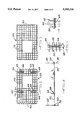
- FIG. 1 is a perspective view of a shipping container embodying the principles of the present invention
- FIGS. 2 and 3 are plan views of the panels which form the top wall of the shipping container illustrated in FIG. 1;
- FIG. 4 is a side elevational view of a portion of the shipping container seen in FIG. 1 showing the closed position of the panels forming its top wall as well as their open position;
- FIG. 5 is a plan view taken substantially along line 5--5 in FIG. 4 of the pin and latch mechanism which is used to secure the panels in their closed position and to one another;
- FIG. 6 is a sectional view taken substantially along line 6--6 in FIG. 2 illustrating the latch portion of the pin and latch mechanism utilized with the present invention.
- FIG. 1 a composite shipping container embodying the principles of the present invention is illustrated in FIG. 1 and generally designated at 10.
- the composite container 10 is principally comprised of an outer container 12 and an inner tank 14.
- the outer container 12 defines a protective and supportive enclosure for the inner tank 14 which is the actual receptacle for the liquids being shipped and stored.
- the outer container 12 includes bottom wall 16, side walls 18 and a top wall 20 which cooperate to define a receiving space for the inner container 14.
- the top wall 20 itself is further made up of a pair of separate top panels 22 and 24 which cooperate to define the top wall 20.
- Dependent legs 26 extend downward, generally from the corners of the bottom wall 16 of the container 12.
- the legs 26 function as risers so as to elevate the container 10 up off of the floor of a warehouse or trailer.
- the legs 26 are also spaced so that the tines of a forklift truck can be inserted under the container 10 thereby facilitating the ease with which the container 10 is handled during transportation and storage.
- the legs 26 could alternatively be provided such that they extend substantially continuously around the bottom wall 16.
- the legs 26 could be of a tubular or other construction and could be formed as part of an integral pallet support structure, including the bottom wall 16, for the container 10. If provided in this alternative manner, the bottom wall 16 itself need not be made of wire mesh material. Instead, the bottom wall 16 could be formed from stamped sheet metal or molded plastic, either of which could be secured to the legs 26.
- the side walls 18 of the outer container 12 designated as a front wall 28, a rear wall 30, a left wall 32 and a right wall 34, are dimensioned such that opposing pairs of the side walls (28, 30 and 32, 34) correspond in width with one another while all of the side walls 18 exhibit the same height.
- a discharge opening 36 is formed in the front wall 28 and located substantially adjacent to the bottom wall 16.
- the top wall 20 has a central fill opening 38 defined by two corresponding openings in the two panels 22 and 24 which define it. While the location of the discharge and fill openings 36 and 38 are specifically designated and shown in the present embodiment, it will be appreciated that these locations may be altered so as to accommodate the fill and discharge fittings of the specific inner tank 14 being used to form the container 10.
- the inner tank 14 is a liquid-tight container and is preferably constructed out of a synthetic resin as a unitary, blow molded container with dimensions that generally correspond to those of the outer container 12.
- the liquid-tight inner tank 14 is positioned within the outer container 12 so that a fill cap and fitting 40 on the top of the tank 14 can be easily accessed through the fill opening 38 defined in the top wall 20 of the outer container 12.
- a discharge fitting 42 is formed on the inner tank 14 so that it will correspond with the discharge opening 36 defined in the front wall 28 of the outer container 12.
- walls of the inner tank 14 are of a thin construction such that, when filled with a liquid, the tank 14 is incapable of supporting itself upright without the structural aid of the side walls 18 of the outer container 12.
- the inner tank 14 is provided with reinforced, thickened regions 44 and 46 extending transversely along the tank's top front and rear edges.
- the thickened regions 44 and 46 provide a vapor expansion area for the liquid in the inner tank 14 and also provide rigidity for the top of the inner tank 14.
- the shipping container 10 permits at least two full containers 10 to be stacked upon one another. This is achieved by positioning the dependent legs 26 of the upper container 10 on the side walls 18 of the lower container 10. If desired, the side walls 18 of the lower container 10 can be provided with extra support wires or other structures to reinforce those areas where the dependent legs 26 of the upper container 10 engage the side walls 18 of the lower container 10.
- the bottom wall 16 is also provided with two upwardly extending portions along opposing edges, designated as edge portions 48.
- the edge portions 48 providing a mounting portion for two of the side walls 18.
- the left and right walls 32 and 34 are fastened along their lower periphery by helical wire connectors 50 to the edge portions 48.
- the helical wire connectors 50 resemble elongated springs and define a horizontal rotational axis for the left and right side walls 32 and 34. While a helical wire connector wire 50 is used in the present embodiment, it is readily apparent that other conventional means permitting this rotational attachment can be employed without compromising the operability of the invention.
- the front wall 28 is fastened to a front edge 52 of the right wall 34.
- the left wall 32 is rotatably fastened by a helical wire connector 50 about a vertical axis defined along the rear edge 54 of the left wall 32.
- the front wall 28 and the rear wall 30 are further fastened by snap loop connectors 56 along the front edge 58 of the left wall and the rear edge 60 of the right wall, respectively.
- the two panels 22 and 24 of the top wall 20 are rotatable attached, also by helical wire connectors 50, to the upper edge of the left and right walls 32 and 34.
- the panels 22 and 24 overlap one another and cooperate so as to form a composite structure extending completely across the top of the inner tank 14.
- the panels 22 and 24 preferably overlap one another between 25-75% of the width of the inner container 14.
- One of the panels, panel 22 in the illustrated embodiments has four latch member 62 welded at 64 to its underside such that each latch member 62 has a pair of loop portions 66 which extend upward through openings in the mesh material forming the panel 22, generally normal to the surface defined by the panel 22.
- the loop portions 66 extend up through openings defined in the mesh material forming the panel 24.
- the loop portions 66 of the latch member 62 are configured to receive a pin 68 which is inserted transversely through the loop portions 66 generally parallel to the surfaces of the panels 22 and 24. In this way, the pins 68 prevent the panels 22 and 24, and the outer container 12, from being inadvertently opened.
- the four latch members 62 which are generally equally located around an opening 70 defined in the panel 22.
- This opening 70 is located on the panel so that when the other panel 24 is lowered on top of it, the opening 70 will correspond with an opening 72 defined in that panel 24.
- These openings 70 and 72 cooperate to define the fill opening 38 mentioned above.
- the inner tank 14 Upon being emptied, the inner tank 14 is removed from the shipping container 10 by first removing the pins 68 from the latch member 62 and then raising the panels 24 and 22 from their closed positions, where they extend across the inner tank 14, to their open positions, generally designated in phantom in FIG. 4, which permit easy withdrawal of the inner tank 14 upwardly out of the outer container 12.
- the panels 22 and 24 can be further rotated so that they extend downward along the left and right walls 32 and 34.
- the snap loop connectors 56 are opened allowing the front and rear walls 28 and 30 to be folded back upon the right and left walls 34 and 32.
- the right and left walls 32 and 34 are then folded down upon the bottom wall 16 and each other.
- the outer container 12 can be easily and conveniently returned to the original liquid supplier without significantly wasting space during transportation.
- the outer container 12 is unfolded, a new inner tank 14 is inserted into the outer container 12 and filled with liquid.
Abstract
Description
Claims (13)
Priority Applications (1)
| Application Number | Priority Date | Filing Date | Title |
|---|---|---|---|
| US08/329,870 US5595318A (en) | 1994-10-27 | 1994-10-27 | Composite container with improved outer shell |
Applications Claiming Priority (1)
| Application Number | Priority Date | Filing Date | Title |
|---|---|---|---|
| US08/329,870 US5595318A (en) | 1994-10-27 | 1994-10-27 | Composite container with improved outer shell |
Publications (1)
| Publication Number | Publication Date |
|---|---|
| US5595318A true US5595318A (en) | 1997-01-21 |
Family
ID=23287370
Family Applications (1)
| Application Number | Title | Priority Date | Filing Date |
|---|---|---|---|
| US08/329,870 Expired - Fee Related US5595318A (en) | 1994-10-27 | 1994-10-27 | Composite container with improved outer shell |
Country Status (1)
| Country | Link |
|---|---|
| US (1) | US5595318A (en) |
Cited By (12)
| Publication number | Priority date | Publication date | Assignee | Title |
|---|---|---|---|---|
| USD422771S (en) * | 1998-03-23 | 2000-04-11 | Schmitt Anthony L | Liquid storage container |
| USD422770S (en) * | 1999-07-02 | 2000-04-11 | Schmitt Anthony L | Combined container and pallet |
| USD422769S (en) * | 1999-07-02 | 2000-04-11 | Schmitt Anthony L | Container pallet |
| US6135324A (en) * | 1998-04-30 | 2000-10-24 | Schmitt; Anthony L. | Liquid storing and dispensing unit |
| US20060131334A1 (en) * | 2004-11-29 | 2006-06-22 | Carlson Ronald S | Stackable container for storing and dispensing liquid |
| US20060261059A1 (en) * | 2003-03-11 | 2006-11-23 | Anita Jokinen | Transportation container |
| US20110132912A1 (en) * | 2007-03-16 | 2011-06-09 | Jordan David L | Universal support arrangement for semi-membrane tank walls |
| US9067729B2 (en) | 2005-09-02 | 2015-06-30 | Sti Holdings, Inc. | Compartmentalized stacking posts and container with compartmentalized stacking posts |
| US10065763B2 (en) | 2016-09-15 | 2018-09-04 | Arena Packaging, Llc | Wall latching system |
| US20180362237A1 (en) * | 2015-12-23 | 2018-12-20 | Protechna S.A. | Transporting and storage container for liquids |
| US20220267049A1 (en) * | 2021-02-23 | 2022-08-25 | Monsanto Technology Llc | Packaging Assemblies for Product Components, and Related Methods |
| USD979241S1 (en) | 2021-02-23 | 2023-02-28 | Monsanto Technology Llc | Caged co-pack container |
Citations (18)
| Publication number | Priority date | Publication date | Assignee | Title |
|---|---|---|---|---|
| US3964636A (en) * | 1974-02-27 | 1976-06-22 | Houston Rehrig | Box for encasing a bag containing liquid |
| US3970209A (en) * | 1974-05-15 | 1976-07-20 | Alan Raymond Baxter | Collapsible container |
| US4054223A (en) * | 1976-06-16 | 1977-10-18 | Liquitainer S.A. | Packings for transport and storage especially of liquid and pasty products |
| US4090633A (en) * | 1977-09-23 | 1978-05-23 | Cari-All Inc. | Collapsible pallet container |
| US4106626A (en) * | 1976-10-26 | 1978-08-15 | Cari-All, Inc. | Stackable material handling container |
| US4221296A (en) * | 1979-03-20 | 1980-09-09 | Don Fell Limited | Shipping assembly |
| US4653658A (en) * | 1985-04-19 | 1987-03-31 | Karpisek Ladislav Stephan | Liquid containers |
| US4676373A (en) * | 1984-11-20 | 1987-06-30 | Helmhold Schneider | Plastic pallet container |
| US4793519A (en) * | 1987-03-23 | 1988-12-27 | Hoover Group, Inc. | Composite shipping container |
| US4795057A (en) * | 1986-04-01 | 1989-01-03 | Sotralentz S.A. | Transport and/or storage container, particularly for a fluid and/or a fine grained loose material |
| US4909387A (en) * | 1988-11-24 | 1990-03-20 | Schuetz Udo | Pallet container with an exchangeable inner container of a synthetic resin and an outer jacket of metal lattice bars |
| US4930661A (en) * | 1987-03-23 | 1990-06-05 | Hoover Group, Inc. | Composite shipping container |
| US5002194A (en) * | 1990-01-29 | 1991-03-26 | Hoover Group, Inc. | Fold up wire frame containing a plastic bottle |
| US5050775A (en) * | 1989-10-31 | 1991-09-24 | International Paper Company | Beverage dispenser and cup holder |
| US5060815A (en) * | 1989-02-05 | 1991-10-29 | Sotralentz S. A. | Transport and storage container for fluent material |
| US5101995A (en) * | 1990-12-20 | 1992-04-07 | Cari-All, Inc. | Wire-mesh material handling container with improved latches |
| US5110000A (en) * | 1991-02-11 | 1992-05-05 | Hoover Group, Inc. | Composite shipping container with separable top and bottom structures |
| US5366090A (en) * | 1991-11-14 | 1994-11-22 | Schuetz Udo | Pallet container |
-
1994
- 1994-10-27 US US08/329,870 patent/US5595318A/en not_active Expired - Fee Related
Patent Citations (18)
| Publication number | Priority date | Publication date | Assignee | Title |
|---|---|---|---|---|
| US3964636A (en) * | 1974-02-27 | 1976-06-22 | Houston Rehrig | Box for encasing a bag containing liquid |
| US3970209A (en) * | 1974-05-15 | 1976-07-20 | Alan Raymond Baxter | Collapsible container |
| US4054223A (en) * | 1976-06-16 | 1977-10-18 | Liquitainer S.A. | Packings for transport and storage especially of liquid and pasty products |
| US4106626A (en) * | 1976-10-26 | 1978-08-15 | Cari-All, Inc. | Stackable material handling container |
| US4090633A (en) * | 1977-09-23 | 1978-05-23 | Cari-All Inc. | Collapsible pallet container |
| US4221296A (en) * | 1979-03-20 | 1980-09-09 | Don Fell Limited | Shipping assembly |
| US4676373A (en) * | 1984-11-20 | 1987-06-30 | Helmhold Schneider | Plastic pallet container |
| US4653658A (en) * | 1985-04-19 | 1987-03-31 | Karpisek Ladislav Stephan | Liquid containers |
| US4795057A (en) * | 1986-04-01 | 1989-01-03 | Sotralentz S.A. | Transport and/or storage container, particularly for a fluid and/or a fine grained loose material |
| US4793519A (en) * | 1987-03-23 | 1988-12-27 | Hoover Group, Inc. | Composite shipping container |
| US4930661A (en) * | 1987-03-23 | 1990-06-05 | Hoover Group, Inc. | Composite shipping container |
| US4909387A (en) * | 1988-11-24 | 1990-03-20 | Schuetz Udo | Pallet container with an exchangeable inner container of a synthetic resin and an outer jacket of metal lattice bars |
| US5060815A (en) * | 1989-02-05 | 1991-10-29 | Sotralentz S. A. | Transport and storage container for fluent material |
| US5050775A (en) * | 1989-10-31 | 1991-09-24 | International Paper Company | Beverage dispenser and cup holder |
| US5002194A (en) * | 1990-01-29 | 1991-03-26 | Hoover Group, Inc. | Fold up wire frame containing a plastic bottle |
| US5101995A (en) * | 1990-12-20 | 1992-04-07 | Cari-All, Inc. | Wire-mesh material handling container with improved latches |
| US5110000A (en) * | 1991-02-11 | 1992-05-05 | Hoover Group, Inc. | Composite shipping container with separable top and bottom structures |
| US5366090A (en) * | 1991-11-14 | 1994-11-22 | Schuetz Udo | Pallet container |
Cited By (18)
| Publication number | Priority date | Publication date | Assignee | Title |
|---|---|---|---|---|
| USD422771S (en) * | 1998-03-23 | 2000-04-11 | Schmitt Anthony L | Liquid storage container |
| US6135324A (en) * | 1998-04-30 | 2000-10-24 | Schmitt; Anthony L. | Liquid storing and dispensing unit |
| USRE38785E1 (en) | 1998-04-30 | 2005-08-30 | Ronald S. Carlson | Liquid storing and dispensing unit |
| USD422770S (en) * | 1999-07-02 | 2000-04-11 | Schmitt Anthony L | Combined container and pallet |
| USD422769S (en) * | 1999-07-02 | 2000-04-11 | Schmitt Anthony L | Container pallet |
| US20060261059A1 (en) * | 2003-03-11 | 2006-11-23 | Anita Jokinen | Transportation container |
| US20060131334A1 (en) * | 2004-11-29 | 2006-06-22 | Carlson Ronald S | Stackable container for storing and dispensing liquid |
| US9334107B2 (en) | 2005-09-02 | 2016-05-10 | Sti Holdings, Inc. | Gusseted container and method of manufacturing same |
| US9487352B2 (en) | 2005-09-02 | 2016-11-08 | Sti Holdings, Inc. | Container with supports |
| US9067729B2 (en) | 2005-09-02 | 2015-06-30 | Sti Holdings, Inc. | Compartmentalized stacking posts and container with compartmentalized stacking posts |
| US8430263B2 (en) * | 2007-03-16 | 2013-04-30 | General Dynamics Nassco | Universal support arrangement for semi-membrane tank walls |
| US20110132912A1 (en) * | 2007-03-16 | 2011-06-09 | Jordan David L | Universal support arrangement for semi-membrane tank walls |
| US20180362237A1 (en) * | 2015-12-23 | 2018-12-20 | Protechna S.A. | Transporting and storage container for liquids |
| US10875696B2 (en) * | 2015-12-23 | 2020-12-29 | Protechna S.A. | Transporting and storage container for liquids |
| US10065763B2 (en) | 2016-09-15 | 2018-09-04 | Arena Packaging, Llc | Wall latching system |
| US20220267049A1 (en) * | 2021-02-23 | 2022-08-25 | Monsanto Technology Llc | Packaging Assemblies for Product Components, and Related Methods |
| WO2022182557A1 (en) * | 2021-02-23 | 2022-09-01 | Monsanto Technology Llc | Packaging assemblies for product components, and related methods |
| USD979241S1 (en) | 2021-02-23 | 2023-02-28 | Monsanto Technology Llc | Caged co-pack container |
Similar Documents
| Publication | Publication Date | Title |
|---|---|---|
| US5002194A (en) | Fold up wire frame containing a plastic bottle | |
| EP0284290B1 (en) | Composite shipping container | |
| US4930661A (en) | Composite shipping container | |
| EP0511781B1 (en) | Foldable container | |
| AU2001253272B2 (en) | Drop box container | |
| US5564599A (en) | Foldable shipping container | |
| US6015057A (en) | Flexible container for flowable materials | |
| US3964636A (en) | Box for encasing a bag containing liquid | |
| RU2083452C1 (en) | Reservoir on frame pan | |
| US5595318A (en) | Composite container with improved outer shell | |
| US5366090A (en) | Pallet container | |
| JP3497129B2 (en) | Containers for transport and storage of liquids | |
| AU2001253272A1 (en) | Drop box container | |
| US6029839A (en) | Collapsible shipping container | |
| US4880141A (en) | Pallets supported reinforced container | |
| JP2670766B2 (en) | Pallet containers for transport and storage of liquids | |
| US3294307A (en) | Collapsible bin box | |
| GB2283728A (en) | Container | |
| JPH08337288A (en) | Pallet with discharging function for container | |
| JP3016961U (en) | Container for transporting vegetables, etc. | |
| JPH0754152Y2 (en) | Sanitary ware protective material | |
| WO2014046615A1 (en) | Foldable open top container | |
| IES60612B2 (en) | Container for use in transporting goods |
Legal Events
| Date | Code | Title | Description |
|---|---|---|---|
| AS | Assignment |
Owner name: HOOVER GROUP, INC., GEORGIA Free format text: ASSIGNMENT OF ASSIGNORS INTEREST;ASSIGNOR:BARNO, KEITH;REEL/FRAME:007214/0025 Effective date: 19941021 |
|
| AS | Assignment |
Owner name: HOOVER MATERIALS HANDLING GROUP, INC., GEORGIA Free format text: ASSIGNMENT OF ASSIGNORS INTEREST;ASSIGNOR:HOOVER GROUP, INC.;REEL/FRAME:007511/0821 Effective date: 19950101 |
|
| AS | Assignment |
Owner name: NATIONSBANK OF GEORGIA, NATIONAL ASSOCIATION, AS A Free format text: ASSIGNMENT OF ASSIGNORS INTEREST;ASSIGNOR:HOOVER MATERIALS HANDLING GROUP, INC.;REEL/FRAME:007596/0877 Effective date: 19950101 |
|
| AS | Assignment |
Owner name: NATIONSBANK OF GEORGIA, NATIONAL ASSOCIATION, AS A Free format text: SECURITY INTEREST;ASSIGNOR:HOOVER MATERIALS HANDLING GROUP, INC.;REEL/FRAME:007696/0839 Effective date: 19950101 |
|
| AS | Assignment |
Owner name: NATIONSBANK, NATIONAL ASSOCIATION, AS AGENT, NORTH Free format text: CONDITIONAL ASSIGNMENT;ASSIGNOR:HOOVER GROUP, INC.;REEL/FRAME:008999/0721 Effective date: 19980115 |
|
| FEPP | Fee payment procedure |
Free format text: PAYOR NUMBER ASSIGNED (ORIGINAL EVENT CODE: ASPN); ENTITY STATUS OF PATENT OWNER: LARGE ENTITY |
|
| FPAY | Fee payment |
Year of fee payment: 4 |
|
| AS | Assignment |
Owner name: GMAC COMMERCIAL CREDIT LLC, NEW YORK Free format text: SECURITY INTEREST;ASSIGNOR:HOOVER GROUP, INC.;REEL/FRAME:011763/0761 Effective date: 20010507 |
|
| AS | Assignment |
Owner name: HOOVER GROUP, INC., GEORGIA Free format text: RELEASE;ASSIGNOR:NATIONSBANK, NATIONAL ASSOCIATION, AS AGENT;REEL/FRAME:011887/0247 Effective date: 20010507 |
|
| FPAY | Fee payment |
Year of fee payment: 8 |
|
| AS | Assignment |
Owner name: HOOVER GROUP, INC., GEORGIA Free format text: RELEASE, QUITCLAIM, AND ASSIGNMENT;ASSIGNOR:BANK OF AMERICA, N.A.;REEL/FRAME:015334/0146 Effective date: 20041104 Owner name: HOOVER MATERIALS HANDLING GROUP, INC., GEORGIA Free format text: RELEASE, QUITCLAIM, AND ASSIGNMENT;ASSIGNOR:BANK OF AMERICA, N.A.;REEL/FRAME:015334/0146 Effective date: 20041104 |
|
| AS | Assignment |
Owner name: HOOVER GROUP, INC., GEORGIA Free format text: RELEASE OF SECURITY AGREEMENT;ASSIGNOR:GMAC COMMERCIAL FINANCE, LLC;REEL/FRAME:015740/0766 Effective date: 20050124 |
|
| AS | Assignment |
Owner name: CIT GROUP/BUSINESS CREDIT INC., THE, GEORGIA Free format text: SECURITY INTEREST;ASSIGNOR:HOOVER GROUP, INC.;REEL/FRAME:016172/0213 Effective date: 20050125 |
|
| AS | Assignment |
Owner name: THE CIT GROUP/BUSINESS CREDIT, INC., GEORGIA Free format text: AMENDED AND RESTATED PATENT AND TRADEMARK SECURITY AGREEMENT;ASSIGNORS:HOOVER GROUP, INC.;HOOVER MATERIALS HANDLING GROUP, INC.;REEL/FRAME:018375/0637 Effective date: 20060908 |
|
| REMI | Maintenance fee reminder mailed | ||
| LAPS | Lapse for failure to pay maintenance fees | ||
| STCH | Information on status: patent discontinuation |
Free format text: PATENT EXPIRED DUE TO NONPAYMENT OF MAINTENANCE FEES UNDER 37 CFR 1.362 |
|
| FP | Lapsed due to failure to pay maintenance fee |
Effective date: 20090121 |
|
| AS | Assignment |
Owner name: HOOVER GROUP, INC., TEXAS Free format text: RELEASE BY SECURED PARTY;ASSIGNOR:CIT GROUP/BUSINESS CREDIT, INC.;REEL/FRAME:022824/0558 Effective date: 20090304 Owner name: PNC BANK, NATIONAL ASSOCIATION, PENNSYLVANIA Free format text: SECURITY AGREEMENT;ASSIGNORS:HOOVER GROUP, INC.;HOOVER MATERIALS HANDLING GROUP, INC.;HOOVER INVESTMENTS, INC.;REEL/FRAME:022824/0550 Effective date: 20090304 |