US5594535A - Refillable toner cartridge - Google Patents
Refillable toner cartridge Download PDFInfo
- Publication number
- US5594535A US5594535A US08/553,218 US55321895A US5594535A US 5594535 A US5594535 A US 5594535A US 55321895 A US55321895 A US 55321895A US 5594535 A US5594535 A US 5594535A
- Authority
- US
- United States
- Prior art keywords
- cartridge
- toner
- refill
- frame
- pack
- Prior art date
- Legal status (The legal status is an assumption and is not a legal conclusion. Google has not performed a legal analysis and makes no representation as to the accuracy of the status listed.)
- Expired - Lifetime
Links
Images


Classifications
-
- G—PHYSICS
- G03—PHOTOGRAPHY; CINEMATOGRAPHY; ANALOGOUS TECHNIQUES USING WAVES OTHER THAN OPTICAL WAVES; ELECTROGRAPHY; HOLOGRAPHY
- G03G—ELECTROGRAPHY; ELECTROPHOTOGRAPHY; MAGNETOGRAPHY
- G03G15/00—Apparatus for electrographic processes using a charge pattern
- G03G15/06—Apparatus for electrographic processes using a charge pattern for developing
- G03G15/08—Apparatus for electrographic processes using a charge pattern for developing using a solid developer, e.g. powder developer
- G03G15/0894—Reconditioning of the developer unit, i.e. reusing or recycling parts of the unit, e.g. resealing of the unit before refilling with toner
-
- G—PHYSICS
- G03—PHOTOGRAPHY; CINEMATOGRAPHY; ANALOGOUS TECHNIQUES USING WAVES OTHER THAN OPTICAL WAVES; ELECTROGRAPHY; HOLOGRAPHY
- G03G—ELECTROGRAPHY; ELECTROPHOTOGRAPHY; MAGNETOGRAPHY
- G03G15/00—Apparatus for electrographic processes using a charge pattern
- G03G15/06—Apparatus for electrographic processes using a charge pattern for developing
- G03G15/08—Apparatus for electrographic processes using a charge pattern for developing using a solid developer, e.g. powder developer
- G03G15/0822—Arrangements for preparing, mixing, supplying or dispensing developer
- G03G15/0877—Arrangements for metering and dispensing developer from a developer cartridge into the development unit
- G03G15/0881—Sealing of developer cartridges
- G03G15/0884—Sealing of developer cartridges by a sealing film to be ruptured or cut
-
- G—PHYSICS
- G03—PHOTOGRAPHY; CINEMATOGRAPHY; ANALOGOUS TECHNIQUES USING WAVES OTHER THAN OPTICAL WAVES; ELECTROGRAPHY; HOLOGRAPHY
- G03G—ELECTROGRAPHY; ELECTROPHOTOGRAPHY; MAGNETOGRAPHY
- G03G2215/00—Apparatus for electrophotographic processes
- G03G2215/00987—Remanufacturing, i.e. reusing or recycling parts of the image forming apparatus
-
- G—PHYSICS
- G03—PHOTOGRAPHY; CINEMATOGRAPHY; ANALOGOUS TECHNIQUES USING WAVES OTHER THAN OPTICAL WAVES; ELECTROGRAPHY; HOLOGRAPHY
- G03G—ELECTROGRAPHY; ELECTROPHOTOGRAPHY; MAGNETOGRAPHY
- G03G2215/00—Apparatus for electrophotographic processes
- G03G2215/06—Developing structures, details
- G03G2215/066—Toner cartridge or other attachable and detachable container for supplying developer material to replace the used material
- G03G2215/0682—Bag-type non-rigid container
-
- G—PHYSICS
- G03—PHOTOGRAPHY; CINEMATOGRAPHY; ANALOGOUS TECHNIQUES USING WAVES OTHER THAN OPTICAL WAVES; ELECTROGRAPHY; HOLOGRAPHY
- G03G—ELECTROGRAPHY; ELECTROPHOTOGRAPHY; MAGNETOGRAPHY
- G03G2215/00—Apparatus for electrophotographic processes
- G03G2215/06—Developing structures, details
- G03G2215/066—Toner cartridge or other attachable and detachable container for supplying developer material to replace the used material
- G03G2215/069—Toner cartridge or other attachable and detachable container for supplying developer material to replace the used material using a sealing member to be ruptured or cut
-
- G—PHYSICS
- G03—PHOTOGRAPHY; CINEMATOGRAPHY; ANALOGOUS TECHNIQUES USING WAVES OTHER THAN OPTICAL WAVES; ELECTROGRAPHY; HOLOGRAPHY
- G03G—ELECTROGRAPHY; ELECTROPHOTOGRAPHY; MAGNETOGRAPHY
- G03G2221/00—Processes not provided for by group G03G2215/00, e.g. cleaning or residual charge elimination
- G03G2221/16—Mechanical means for facilitating the maintenance of the apparatus, e.g. modular arrangements and complete machine concepts
- G03G2221/18—Cartridge systems
- G03G2221/183—Process cartridge
-
- Y—GENERAL TAGGING OF NEW TECHNOLOGICAL DEVELOPMENTS; GENERAL TAGGING OF CROSS-SECTIONAL TECHNOLOGIES SPANNING OVER SEVERAL SECTIONS OF THE IPC; TECHNICAL SUBJECTS COVERED BY FORMER USPC CROSS-REFERENCE ART COLLECTIONS [XRACs] AND DIGESTS
- Y10—TECHNICAL SUBJECTS COVERED BY FORMER USPC
- Y10S—TECHNICAL SUBJECTS COVERED BY FORMER USPC CROSS-REFERENCE ART COLLECTIONS [XRACs] AND DIGESTS
- Y10S222/00—Dispensing
- Y10S222/01—Xerography
Definitions
- the present invention relates to a toner cartridge used in electrophotographic imaging systems and more particularly, to a new toner cartridge design that can be easily refilled.
- Electrophotographic processes for producing a permanent image on media are well known and commonly used. In general, these processes all include: (1) charging a photoreceptor which is a roller or continuous belt bearing a photoconductive material; (2) exposing the charged area to a light image to produce an electrostatic charge on the area in the shape of the image; (3) presenting developer particles (toner) to the photoreceptor surface bearing the image so that the particles are transferred to the surface in the shape of the image; (4) transferring the particles in the shape of the image from the photoreceptor to the media; (5) fusing or fixing the particles in the shape of the image to the media; and (6) cleaning or restoring the photoreceptor for the next printing cycle.
- image forming apparatus utilize the electrophotographic printing process, examples being laser printers, copy machines, and facsimile machines. As described above, these image forming apparatus use toner to print or copy the desired image or words onto a piece of paper or media.
- the toner is contained in a hopper, which must be refilled periodically. For example, the toner in a laser printer must be refilled after printing approximately 1000 pages.
- Toner the "ink" of the print or copy machine
- Toner is a powdery substance that must be applied evenly across the surface of the photoconductive drum during use.
- toner that leaks out of the hopper during shipping can accumulate on the drum and cause blotching, streaking or voiding of prints and copies.
- Toner leakage can also cause moving parts to wear out more rapidly and may even short out the electrical components in the cartridge. In these ways, toner leakage reduces the quality of prints and copies, increases maintenance cost, and can even decrease the useful life of the image forming machine.
- a disposable toner cartridge is generally used.
- This cartridge typically includes a toner hopper, seal assembly, mounting member, magnetic roller assembly, photoconductive drum assembly and corona assembly.
- toner is applied equally across the surface of the drum without leaking out of the hopper during shipping.
- this cartridge design is relatively expensive.
- the magnetic roller, drum and corona assemblies last considerably longer than 1000 pages. Thus, the disposal of the entire cartridge results in unnecessary waste of material and landfill space with the costs being passed on to the consumer.
- Toner leakage is prevented by the seal assembly which is typically provided with a removable seal member. Once this seal member is removed, toner is allowed to flow out of the toner hopper opening onto the charged developer sleeve and across the surface of the drum as understood by one skilled in the art. Removal of the seal member also allows toner to permeate throughout the entire cartridge if shaken or flipped upside down. Consequently, the seal member is usually not removed until after the cartridge has been inserted into an image forming machine.
- the present invention is an apparatus for refilling an electrophotographic imaging system.
- a limited number of refill packs can be snapped onto a cartridge.
- the refill pack is constructed around a frame.
- the refill pack attaches to a receiving area on the cartridge.
- a receiving area on the cartridge In the receiving area of the cartridge, there is an opening passing from within the cartridge to outside the cartridge.
- a new cartridge includes a flexible cover attached over the opening in the receiving area.
- the removable seal is removed. As the removable seal is removed, a cutting edge on the removable seal cuts the flexible cover, opening the cartridge. Removal of the removable seal also releases the developer particles from the internal volume, allowing them to enter the cartridge thereby refilling the cartridge.
- additional refill packs may be added over the top of a spent refill pack.
- the receiving area of the cartridge allows a maximum number of refill packs.
- the removable seal includes a tab that locks into the flexible cover when the refill pack is attached to the cartridge. Extraction of the removable seal also extracts the flexible cover.
- FIG. 1 is a perspective view of the preferred embodiment in accordance with the present invention.
- FIG. 2 is a simplified cross sectional view of a new toner cartridge.
- FIG. 3 is a simplified cross sectional view of a new toner cartridge showing a spring force to aid in collapsing the toner bag.
- FIG. 4 is a simplified cross sectional view of an expired toner cartridge.
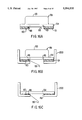
- FIG. 5 is a simplified cross sectional view of the toner refill area of a toner cartridge showing the addition of a refill cartridge for refilling the toner cartridge.
- FIG. 6 is a simplified cross sectional view of the toner refill area of a toner cartridge showing the addition of a second refill cartridge for refilling the toner cartridge.
- FIG. 7 is a simplified cross sectional view of the toner refill area of a toner cartridge showing the maximum number of refill cartridges for refilling the toner cartridge.
- FIG. 8 is a simplified cross sectional view of the refill cartridge.
- FIG. 9 is a perspective view of the refill cartridge.
- FIG. 10 is a perspective view of the toner cartridge with a refill cartridge about to be installed.
- FIG. 11 is a close-up perspective view of refill cartridge locking snaps.
- FIG. 12 is a close-up perspective view of refill cartridge.
- FIG. 13 in an alternative embodiment of a frame that includes spring action locking tabs.
- FIG. 14 shows the seal being removed.
- FIG. 15 is a perspective view an alternative embodiment for the refill cartridge.
- FIG. 16 is a cross sectional view of an alternative embodiment for the refill cartridge.
- FIG. 17 in an alternative embodiment for removing the seals when installing a refill cartridge.
- FIG. 18 is a simplified cross sectional view showing a "toner gage" to indicate an approximate amount of remaining toner.
- FIG. 19 in an alternative embodiment of the "toner gage.”
- FIG. 20 is a perspective view of an alternative embodiment showing the toner cartridge with a refill cartridge about to be installed.
- FIG. 21 is a perspective view of an alternative embodiment showing the toner cartridge.
- FIG. 22 is a cross sectional view of the refill cartridge along lines A--A of FIG. 20.
- FIG. 23 is a close-up view of the locking tab.
- FIG. 24 is a close-up perspective view of refill cartridge receiving area of the toner cartridge.
- FIG. 25 is a perspective view of another alternative embodiment showing the toner cartridge with a refill cartridge about to be installed.
- the electrophotographic printer 300 has therein feed rollers 321 and 322 for feeding the printing sheets stacked in the printing sheet cassettes 311 and 312, a pair of rollers 323 for conveying a printing sheet fed from the printing sheet cassettes 311 or 312, an exposure array 376 for emitting light to the photosensitive drum 83 for thereby forming an electrostatic latent image on the photosensitive drum 83, a transfer electrostatic charger 327 for transferring toner from the photosensitive drum 83 to the printing sheet, a pair of heat rollers 328 for fixing the toner transferred on the printing sheet and a toner cartridge 200.
- the toner cartridge 200 has an electrostatic charger 84 for electrostatic charging the photosensitive drum 83 uniformly, a cleaner 76 for eliminating the untransferred or waste toner on the photosensitive drum 83 as well as the developing roller 82 and the photosensitive drum 83.
- Charging roller 84 provides the uniform electrostatic charge on photosensitive drum 83.
- Toner 81 is applied to photosensitive drum 83 through developer 82 roller. After the electrostatic latent image is transferred from photosensitive drum 83, any waste toner is removed and stored in waste hopper 86.
- a flexible cover 85 is formed over toner 81. Flexible cover 85 collapses as toner 81 is consumed. Also shown in FIG;. 2 is cartridge seal 50. Cartridge seal 50 seals toner 81 during transportation of toner cartridge 200. Prior to inserting toner cartridge 200 into the printing apparatus 300, cartridge seal 50 must be removed. However, once cartridge seal 50 has been removed, toner 81 is allowed passage towards developer 82. With the present design of toner cartridge 200, cartridge seal 50 cannot be replaced without dissecting toner cartridge 200.
- an optional spring 90 which is attached at the upper level to a cover on the printing apparatus 300, provides positive pressure against the flexible cover 85 aiding toner 81 towards developer 82.
- the downward force created by spring 90 provides just enough force to insure that flexible cover 85 collapses as toner 81 is consumed. If the force created by spring 90 is too great, toner 81 will leak past developer 82 in an undesirable fashion.
- the exact spring force is dependent upon numerous factors, however, the predominant factor is the thickness and material type used to manufacture the flexible cover 85.
- FIG. 4 shows the position of flexible cover 85 and spring 90 when the toner cartridge 200 is ready for refilling.
- a new refill cartridge 59 attaches over the top of the consumed flexible cover 85.
- pull strip 87 seals the new refill cartridge 59.
- knife 52 punchers the flexible cover 85 thereby allowing the new toner in refill cartridge 59 to mix with the remaining old toner 81.
- Bag frame 54 seals against toner cartridge 200 during the installation of refill cartridge 59. Thus, with this operation, toner can be replenished without exposing the user to toner.
- An additional refill cartridge 61 can be added to the refill area, as shown in FIG. 6.
- the refilling area can be sized such that a maximum number of refills can be added.
- the photosensitive drum 83 has and life expectancy of 6000 pages.
- the toner cartridge 200 is originally filled with enough toner to print approximately 1000 pages and that each refill cartridge adds an additional printing capacity of 1000 pages each.
- the refilling area should accept a maximum of five additional refill cartridge. As shown in FIG. 7, once the fifth refill cartridge is added, the refill area is fully occupied.
- FIGS. 8 and 9 where a cross section view of the refill cartridge 59 is shown.
- a compressible foam 51 is formed around the bottom and outer edges of frame 54.
- compressible foam 51 forms a seal against the toner cartridge thereby, containing toner 81 within the toner cartridge 200.
- Seal 87 which is present during shipment of refill cartridge 59, prevents toner leakage until seal 87 is removed. After refill cartridge 59 is installed in toner cartridge 200 the seal 87 is removed by the user. As seal 87 is removed, cutting edge 52 punctures the underlying toner bag allowing toner 81 to enter the toner hopper in toner cartridge 200.
- FIG. 10 gives a perspective view of toner cartridge 200 and refill cartridge 59. Upon close examination of toner cartridge 200, a plurality of snaps 30 can be seen. These one-way snaps, snap against refill cartridge frame 54 when refill cartridge 59 is inserted in toner cartridge 200.
- the one way snaps 30, prevent refill cartridge 59 from being removed from toner cartridge 200 after insertion. This prevention accomplishes two important functions. First, if refill cartridge 59 were removed after pull strap 87 has been removed, there is a good chance that toner will spill out exposing the user to the messy toner. Second, as stated above during discussion of FIG. 7, many of the components within toner cartridge 200 have a limited life span. If refill cartridge 59 is removed after it has been depleted, additional toner might be added such that toner cartridge 200 is used beyond its designed life span.
- Toner cartridge 200 has a plurality of snaps 30. Also shown is cutout 90 which allows snaps 30 adjacent to cutout 90 to exhibit a slight lateral movement when additional refill cartridges are added.
- FIG. 12 the end of a refill cartridge 59 is shown.
- the refill cartridge consists of a toner bag 53, frame 54, foam 51, and seal 87.
- indent 91 is constructed to mate with the openings as shown in FIG. 11.
- FIG. 13 An alternative embodiment to frame 54 is shown in FIG. 13.
- tabs 92 as shown on frame 54, the cutout 99 of FIG. 11 can be eliminated.
- tabs 92 compress as they pass over snaps 30. Once the refill cartridge is in place, tabs 92 expand thereby locking the refill cartridge to the toner cartridge.
- the two embodiments for attaching the refill cartridge to the toner cartridge shown and described here are only exemplary, other structures that accomplish the same function as understood by one of ordinary skill could be used.
- FIG. 14 shows the seal 87 being removed from refill cartridge 59.
- the seal 87 is shown in its normal position. As the seal 87 is extracted by the user, the toner in refill cartridge 59 can escape.
- FIG. 14B indicates that the seal 87 is 50% removed.
- FIG. 15 An alternative embodiment of refill cartridge 59 is shown in FIG. 15. As before, seal 87, frame 54, and foam 51 construct the refill cartridge. In this embodiment, a pair of serrated cutting edges 55 and 49 are used to aid in tearing the previous refill cartridge.
- FIGS. 16A-16C a cross sectional view of the refill cartridge of FIG. 15 is shown. There is shown a cutting edge 55 which pivots about pivot point 48. As the refill cartridge 59 is inserted into the toner cartridge 200, tab 60 is pressed against the toner cartridge housing. As foam 51 compresses, the force on tab 60 causes the cutting edge 55 to pivot about pivot point 48. There is also shown the second cutting edge 49 which aids in cutting toner bag 53 when a subsequent refill cartridge is placed over the present refill cartridge 59 area. In FIG. 16C the cutting edge 55 has completely pivoted about pivot point 48 as foam 51 compresses. Cutting edge 55 is intended to puncture the underlying previous toner bag 53.
- blade 49 When a subsequent toner refill package is placed on top of the present refill cartridge as in FIG. 16D, blade 49 holds the present refill cartridge toner bag in place as the subsequent cutting edge pivots about its own pivot point. Thus, the upwardly thrusting cutting edge 49 provides an upward cutting force against the downward pivoting cutting action of the subsequent cartridge.
- FIG. 17 shows another embodiment to insure that toner in a new refill cartridge is allowed passage past prior refill cartridges.
- lower hook 23 attaches to upper hook 22 on the previous refill cartridge.
- seal 87 is extracted to release toner from the new refill cartridge 59. Because lower hook 23 is locked to upper hook 22, extraction of seal 87 also opens the top of toner bag 53 allowing toner to refill the empty chamber.
- a "toner gage” that provides a visual indication of an approximate amount of remaining toner can be constructed as shown in FIGS. 18 and 19.
- toner gage 220 moves down as spring 90 presses the toner out of the refill cartridge 59.
- toner gage 1002 rotates as a result of spring 1003 tension. As the toner in toner bag 1001 is consumed, toner gage 1002 pivots towards the "E" symbol. Also shown in FIG. 19 is exhausted toner bag 1000.
- FIG. 20 shows an alternative embodiment to the present invention that allows only one refill pack 153 to be added to toner cartridge 200.
- the refill pack 153 is snapped over the top of toner cartridge 200.
- tab 400 locks into receptacle 451 of cover 450.
- cover 450 shown in FIG. 21, is simultaneously removed, allowing toner in refill pack 153 to refill toner cartridge 200.
- the cover 450 is recessed so that it is only removable when refill pack 153 is installed. Also shown is the original pull strip seal 50 which the user must remove before printing with a new cartridge toner cartridge 200.
- FIG. 22 provides a cross sectional view along lines A--A of FIG. 20.
- Toner 81 is bounded by refill pack 153 and seal 187.
- Seal 187 slides into place along grooves 190A and 190B.
- Foam 191 creates a toner tight seal against toner cartridge 200 when refill pack 153 is properly installed on toner cartridge 200.
- tab 400 is more clearly shown. It should be noted that the exact shape and size of tab 400 is not important to the present invention. One skilled in the art understands that numerous embodiments exists for tab 400 provided it performs the desired function. Tab 400 must protrude through receptacle 451 and sufficiently transfer lateral forces against seal 187 to extract cover 450 along with seal 187.
- FIG. 24 provides a close up view of the docking area between toner cartridge 200 and refill pack 153.
- Receptacle 451 is tightly held in place in a similar manner as seal 187.
- the lateral force transferred to cover 450 through receptacle 451 and tab 400 causes cover 450 to climb ledge 193.
- cover 450 travels out of toner cartridge 200, the far edges of cover 450 must climb ledges 193 and ride over surface 195. Because the outer edges travel over surface 195, cover 450 experiences a slight bow.
- foam 191 on refill pack 153 seals against toner cartridge 200 and simultaneously seals opening 194, thereby forming a toner tight seal between refill pack 153 and toner cartridge 200.
- Toner cartridge 200 is arranged to receive a refill cartridge 159.
- the refill cartridge 159 consists of a seal 87 and a tab 400.
- Along the lower surface of refill cartridge 159 is a self sealing foam 51.
- Toner cartridge 200 consist of a cover 450 which includes a receptacle 451. Also shown are four guides 502 on each side of the receiving area. Along the outside receiving area, are shown four snaps 500. These snaps rigidly attach refill package 159 to the toner cartridge.
Abstract
Description
Claims (8)
Priority Applications (1)
| Application Number | Priority Date | Filing Date | Title |
|---|---|---|---|
| US08/553,218 US5594535A (en) | 1995-11-07 | 1995-11-07 | Refillable toner cartridge |
Applications Claiming Priority (1)
| Application Number | Priority Date | Filing Date | Title |
|---|---|---|---|
| US08/553,218 US5594535A (en) | 1995-11-07 | 1995-11-07 | Refillable toner cartridge |
Publications (1)
| Publication Number | Publication Date |
|---|---|
| US5594535A true US5594535A (en) | 1997-01-14 |
Family
ID=24208587
Family Applications (1)
| Application Number | Title | Priority Date | Filing Date |
|---|---|---|---|
| US08/553,218 Expired - Lifetime US5594535A (en) | 1995-11-07 | 1995-11-07 | Refillable toner cartridge |
Country Status (1)
| Country | Link |
|---|---|
| US (1) | US5594535A (en) |
Cited By (35)
| Publication number | Priority date | Publication date | Assignee | Title |
|---|---|---|---|---|
| US5761584A (en) * | 1994-12-16 | 1998-06-02 | Canon Kabushiki Kaisha | Process cartridge toner supply container mountable onto toner accommodating container and toner supply method |
| US5802431A (en) * | 1995-04-03 | 1998-09-01 | Canon Kabushiki Kaisha | Collapsible toner container |
| US5946520A (en) * | 1997-06-02 | 1999-08-31 | Hewlett-Packard Company | Anti-fraud pull tab system for printing products |
| US5960238A (en) * | 1997-04-25 | 1999-09-28 | Nec Corporation | Method of supplying toner for process cartridge and process cartridge for image forming apparatus |
| US5974288A (en) * | 1997-10-23 | 1999-10-26 | Canon Kabushiki Kaisha | Electrophotographic image forming apparatus |
| US6055388A (en) * | 1997-04-03 | 2000-04-25 | Ricoh Company, Ltd. | Image forming apparatus and method for obtaining appropriate toner density |
| US6535712B2 (en) | 2001-07-06 | 2003-03-18 | Hewlett-Packard Company | Gloss control method and apparatus with disposable toner cartridges containing clear toners |
| US6654577B1 (en) | 2002-10-24 | 2003-11-25 | Hewlett-Packard Development Company, L.P. | Toner cartridge converter |
| US6665506B1 (en) * | 2002-05-02 | 2003-12-16 | General Plastics Industrial Co., Ltd. | Developing member for an image forming apparatus |
| US6721525B2 (en) | 2001-11-12 | 2004-04-13 | General Plastics Industrial Co., Ltd. | Cartridge with a replaceable toner container for a laser printing imaging apparatus |
| US20040131392A1 (en) * | 2002-09-20 | 2004-07-08 | Junichi Matsumoto | Body member of a powder container |
| US20040247343A1 (en) * | 2002-06-05 | 2004-12-09 | Junichi Matsumoto | Developer container, developer replenishing device using the same and image forming apparatus including the same |
| US20050019045A1 (en) * | 2003-07-23 | 2005-01-27 | Adkins Christopher A. | Method for providing imaging substance for use in an imaging device via a virtual replenishment |
| US6961531B2 (en) | 2002-10-17 | 2005-11-01 | Hewlett-Packard Development Company, L.P. | Refillable print cartridge and method of refilling |
| US20060093384A1 (en) * | 2004-10-29 | 2006-05-04 | Balch Debbie A | Imaging cartridge status indicator |
| US20060182468A1 (en) * | 2004-03-19 | 2006-08-17 | Nobuo Takami | Container holding device, conveying device, image forming apparatus, and method of fixing container |
| US20080205927A1 (en) * | 2007-02-22 | 2008-08-28 | Xerox Corporation | Xerographic customer replacement unit kit |
| US20100080607A1 (en) * | 2008-09-29 | 2010-04-01 | Kyocera Mita Corporation | Developer storage container and image forming apparatus provided therewith |
| US20100189463A1 (en) * | 2004-06-04 | 2010-07-29 | Oki Data Corporation | Image forming apparatus and toner cartridge |
| EP2662733A2 (en) | 2003-12-23 | 2013-11-13 | Sagemcom Documents Sas | Toner refill cartridge system and implementing method thereof |
| US20130308972A1 (en) * | 2012-05-21 | 2013-11-21 | Canon Kabushiki Kaisha | Developer accommodating unit, process cartridge and electrophotographic image forming apparatus |
| US20130308973A1 (en) * | 2011-07-14 | 2013-11-21 | Canon Kabushiki Kaisha | Developer accommodating unit, process cartridge, electrophotographic image forming apparatus |
| US8611781B2 (en) | 2010-02-10 | 2013-12-17 | Static Control Components, Inc. | Method and device of joining multiple parts of a toner cartridge |
| US20140016961A1 (en) * | 2011-07-14 | 2014-01-16 | Canon Kabushiki Kaisha | Developer accommodating container, process cartridge, electrophotographic image forming apparatus |
| US20140064793A1 (en) * | 2012-09-04 | 2014-03-06 | Canon Kabushiki Kaisha | Developing unit, process cartridge and image forming apparatus |
| US20140212181A1 (en) * | 2013-01-25 | 2014-07-31 | Canon Kabushiki Kaisha | Cartridge, developing cartridge, process cartridge and image forming apparatus |
| US20150139684A1 (en) * | 2012-12-14 | 2015-05-21 | Canon Kabushiki Kaisha | Developer accommodating unit with frames for accommodating a developer accomodating member |
| US20150185692A1 (en) * | 2012-07-24 | 2015-07-02 | Sharp Kabushiki Kaisha | Image forming apparatus |
| JP2015222335A (en) * | 2014-05-22 | 2015-12-10 | 株式会社リコー | Toner supply apparatus, process cartridge, and image forming apparatus |
| JP2016085371A (en) * | 2014-10-27 | 2016-05-19 | キヤノン株式会社 | Reproduction method for developer storage unit |
| US20170015541A1 (en) * | 2013-11-13 | 2017-01-19 | TRV Dispense, LLC | Soft Food and Beverage Dispenser |
| US9857726B2 (en) * | 2016-03-18 | 2018-01-02 | Fuji Xerox Co., Ltd. | Accumulation device and image forming apparatus |
| US10175609B2 (en) * | 2011-07-14 | 2019-01-08 | Canon Kabushiki Kaisha | Developer accommodating unit, process cartridge and electrophotographic image forming apparatus |
| US10420355B2 (en) | 2013-11-13 | 2019-09-24 | TRV Dispense, LLC | Soft food and beverage dispenser |
| US11614697B1 (en) | 2021-10-28 | 2023-03-28 | Hewlett-Packard Development Company, L.P. | Modules with inner module spaces for print materials |
Citations (3)
| Publication number | Priority date | Publication date | Assignee | Title |
|---|---|---|---|---|
| US4816877A (en) * | 1988-02-25 | 1989-03-28 | Fred Keen | Refillable toner cartridge and method of manufacture thereof |
| US5185616A (en) * | 1989-05-18 | 1993-02-09 | Berolina Schriftbild Wilcke, Wolff, Busch & Partner Kg | Developer station for a laser printer |
| US5392963A (en) * | 1993-06-01 | 1995-02-28 | Hewlett-Packard Company | Refurbished toner cartridge |
-
1995
- 1995-11-07 US US08/553,218 patent/US5594535A/en not_active Expired - Lifetime
Patent Citations (3)
| Publication number | Priority date | Publication date | Assignee | Title |
|---|---|---|---|---|
| US4816877A (en) * | 1988-02-25 | 1989-03-28 | Fred Keen | Refillable toner cartridge and method of manufacture thereof |
| US5185616A (en) * | 1989-05-18 | 1993-02-09 | Berolina Schriftbild Wilcke, Wolff, Busch & Partner Kg | Developer station for a laser printer |
| US5392963A (en) * | 1993-06-01 | 1995-02-28 | Hewlett-Packard Company | Refurbished toner cartridge |
Cited By (63)
| Publication number | Priority date | Publication date | Assignee | Title |
|---|---|---|---|---|
| US5761584A (en) * | 1994-12-16 | 1998-06-02 | Canon Kabushiki Kaisha | Process cartridge toner supply container mountable onto toner accommodating container and toner supply method |
| US5802431A (en) * | 1995-04-03 | 1998-09-01 | Canon Kabushiki Kaisha | Collapsible toner container |
| US6055388A (en) * | 1997-04-03 | 2000-04-25 | Ricoh Company, Ltd. | Image forming apparatus and method for obtaining appropriate toner density |
| US5960238A (en) * | 1997-04-25 | 1999-09-28 | Nec Corporation | Method of supplying toner for process cartridge and process cartridge for image forming apparatus |
| US5946520A (en) * | 1997-06-02 | 1999-08-31 | Hewlett-Packard Company | Anti-fraud pull tab system for printing products |
| US5974288A (en) * | 1997-10-23 | 1999-10-26 | Canon Kabushiki Kaisha | Electrophotographic image forming apparatus |
| US6535712B2 (en) | 2001-07-06 | 2003-03-18 | Hewlett-Packard Company | Gloss control method and apparatus with disposable toner cartridges containing clear toners |
| US6721525B2 (en) | 2001-11-12 | 2004-04-13 | General Plastics Industrial Co., Ltd. | Cartridge with a replaceable toner container for a laser printing imaging apparatus |
| US6665506B1 (en) * | 2002-05-02 | 2003-12-16 | General Plastics Industrial Co., Ltd. | Developing member for an image forming apparatus |
| US6898405B2 (en) * | 2002-06-05 | 2005-05-24 | Ricoh Company, Ltd. | Developer container, developer replenishing device using the same and image forming apparatus including the same |
| US7065313B2 (en) | 2002-06-05 | 2006-06-20 | Ricoh Company, Ltd. | Developer container, developer replenishing device using the same and image forming apparatus including the same |
| US20040247343A1 (en) * | 2002-06-05 | 2004-12-09 | Junichi Matsumoto | Developer container, developer replenishing device using the same and image forming apparatus including the same |
| US20050180782A1 (en) * | 2002-06-05 | 2005-08-18 | Junichi Matsumoto | Developer container, developer replenishing device using the same and image forming apparatus including the same |
| US7257348B2 (en) | 2002-09-20 | 2007-08-14 | Ricoh Company, Ltd. | Body member of a powder container |
| US20070122207A1 (en) * | 2002-09-20 | 2007-05-31 | Junichi Matsumoto | Body member of a powder container |
| US7593674B2 (en) | 2002-09-20 | 2009-09-22 | Ricoh Company, Ltd. | Body member of a powder container |
| US20080310884A1 (en) * | 2002-09-20 | 2008-12-18 | Junichi Matsumoto | Body member of a powder container |
| US20040131392A1 (en) * | 2002-09-20 | 2004-07-08 | Junichi Matsumoto | Body member of a powder container |
| US7796914B2 (en) | 2002-09-20 | 2010-09-14 | Ricoh Company, Ltd. | Powder container having a cylindrical shutter |
| US7221891B2 (en) * | 2002-09-20 | 2007-05-22 | Ricoh Company, Ltd. | Body member of a powder container |
| US20070189813A1 (en) * | 2002-09-20 | 2007-08-16 | Junichi Matsumoto | Body member of a powder container |
| US6961531B2 (en) | 2002-10-17 | 2005-11-01 | Hewlett-Packard Development Company, L.P. | Refillable print cartridge and method of refilling |
| US6654577B1 (en) | 2002-10-24 | 2003-11-25 | Hewlett-Packard Development Company, L.P. | Toner cartridge converter |
| US20050019045A1 (en) * | 2003-07-23 | 2005-01-27 | Adkins Christopher A. | Method for providing imaging substance for use in an imaging device via a virtual replenishment |
| US7469107B2 (en) * | 2003-07-23 | 2008-12-23 | Lexmark International, Inc. | Method for providing imaging substance for use in an imaging device via a virtual replenishment |
| EP2662733A2 (en) | 2003-12-23 | 2013-11-13 | Sagemcom Documents Sas | Toner refill cartridge system and implementing method thereof |
| EP2662733A3 (en) * | 2003-12-23 | 2014-02-19 | Funai Electric Company Ltd | Toner refill cartridge system and implementing method thereof |
| US20060182468A1 (en) * | 2004-03-19 | 2006-08-17 | Nobuo Takami | Container holding device, conveying device, image forming apparatus, and method of fixing container |
| US7457564B2 (en) * | 2004-03-19 | 2008-11-25 | Ricoh Company, Ltd. | Container holding device, conveying device, image forming apparatus, and method of fixing container |
| US20100189463A1 (en) * | 2004-06-04 | 2010-07-29 | Oki Data Corporation | Image forming apparatus and toner cartridge |
| US7983602B2 (en) * | 2004-06-04 | 2011-07-19 | Oki Data Corporation | Image forming apparatus and toner cartridge |
| US7352976B2 (en) * | 2004-10-29 | 2008-04-01 | Balch Debbie A | Imaging cartridge status indicator |
| US20060093384A1 (en) * | 2004-10-29 | 2006-05-04 | Balch Debbie A | Imaging cartridge status indicator |
| US20080205927A1 (en) * | 2007-02-22 | 2008-08-28 | Xerox Corporation | Xerographic customer replacement unit kit |
| US8185012B2 (en) * | 2008-09-29 | 2012-05-22 | Kyocera Mita Corporation | Developer storage container and image forming apparatus provided therewith |
| US20100080607A1 (en) * | 2008-09-29 | 2010-04-01 | Kyocera Mita Corporation | Developer storage container and image forming apparatus provided therewith |
| US8611781B2 (en) | 2010-02-10 | 2013-12-17 | Static Control Components, Inc. | Method and device of joining multiple parts of a toner cartridge |
| US10620567B2 (en) | 2011-07-14 | 2020-04-14 | Canon Kabushiki Kaisha | Developer accommodating unit, process cartridge and electrophotographic image forming apparatus |
| US20130308973A1 (en) * | 2011-07-14 | 2013-11-21 | Canon Kabushiki Kaisha | Developer accommodating unit, process cartridge, electrophotographic image forming apparatus |
| US20140016961A1 (en) * | 2011-07-14 | 2014-01-16 | Canon Kabushiki Kaisha | Developer accommodating container, process cartridge, electrophotographic image forming apparatus |
| US10175609B2 (en) * | 2011-07-14 | 2019-01-08 | Canon Kabushiki Kaisha | Developer accommodating unit, process cartridge and electrophotographic image forming apparatus |
| CN103649844A (en) * | 2011-07-14 | 2014-03-19 | 佳能株式会社 | Developer storage unit, process cartridge, and electrophotographic image forming device |
| CN103649844B (en) * | 2011-07-14 | 2017-03-08 | 佳能株式会社 | Developer-containing unit, handle box and electrophotographic imaging forming apparatus |
| US8824918B2 (en) * | 2011-07-14 | 2014-09-02 | Canon Kabushiki Kaisha | Developer accommodating unit, process cartridge, electrophotographic image forming apparatus |
| US9152081B2 (en) * | 2011-07-14 | 2015-10-06 | Canon Kabushiki Kaisha | Developer accommodating container, process cartridge, electrophotographic image forming apparatus |
| US9146503B2 (en) * | 2012-05-21 | 2015-09-29 | Canon Kabushiki Kaisha | Developer accommodating unit, process cartridge and electrophotographic image forming apparatus |
| US9471006B2 (en) | 2012-05-21 | 2016-10-18 | Canon Kabushiki Kaisha | Developer accommodating unit, process cartridge and electrophotographic image forming apparatus |
| US20130308972A1 (en) * | 2012-05-21 | 2013-11-21 | Canon Kabushiki Kaisha | Developer accommodating unit, process cartridge and electrophotographic image forming apparatus |
| US9250604B2 (en) * | 2012-07-24 | 2016-02-02 | Sharp Kabushiki Kaisha | Image forming apparatus with high-and low-frequency working sections |
| US20150185692A1 (en) * | 2012-07-24 | 2015-07-02 | Sharp Kabushiki Kaisha | Image forming apparatus |
| US9360831B2 (en) * | 2012-09-04 | 2016-06-07 | Canon Kabushiki Kaisha | Developing unit, process cartridge and image forming apparatus |
| US20140064793A1 (en) * | 2012-09-04 | 2014-03-06 | Canon Kabushiki Kaisha | Developing unit, process cartridge and image forming apparatus |
| US20150139684A1 (en) * | 2012-12-14 | 2015-05-21 | Canon Kabushiki Kaisha | Developer accommodating unit with frames for accommodating a developer accomodating member |
| US9377714B2 (en) * | 2012-12-14 | 2016-06-28 | Canon Kabushiki Kaisha | Developer accommodating unit with frames for accommodating a developer accommodating member |
| US20140212181A1 (en) * | 2013-01-25 | 2014-07-31 | Canon Kabushiki Kaisha | Cartridge, developing cartridge, process cartridge and image forming apparatus |
| US9164424B2 (en) * | 2013-01-25 | 2015-10-20 | Canon Kabushiki Kaisha | Cartridge with flexible developer bag and elastic member for acting on the developer bag |
| US20170015541A1 (en) * | 2013-11-13 | 2017-01-19 | TRV Dispense, LLC | Soft Food and Beverage Dispenser |
| US10017371B2 (en) * | 2013-11-13 | 2018-07-10 | TRV Dispense, LLC | Soft food and beverage dispenser |
| US10420355B2 (en) | 2013-11-13 | 2019-09-24 | TRV Dispense, LLC | Soft food and beverage dispenser |
| JP2015222335A (en) * | 2014-05-22 | 2015-12-10 | 株式会社リコー | Toner supply apparatus, process cartridge, and image forming apparatus |
| JP2016085371A (en) * | 2014-10-27 | 2016-05-19 | キヤノン株式会社 | Reproduction method for developer storage unit |
| US9857726B2 (en) * | 2016-03-18 | 2018-01-02 | Fuji Xerox Co., Ltd. | Accumulation device and image forming apparatus |
| US11614697B1 (en) | 2021-10-28 | 2023-03-28 | Hewlett-Packard Development Company, L.P. | Modules with inner module spaces for print materials |
Similar Documents
| Publication | Publication Date | Title |
|---|---|---|
| US5594535A (en) | Refillable toner cartridge | |
| JPH07261492A (en) | Developer unit | |
| US20030223776A1 (en) | Developer cartridge and image forming apparatus | |
| JP2008145936A (en) | Process cartridge and image forming apparatus | |
| US9785086B2 (en) | Developer container, developing device, process cartridge, and image forming apparatus | |
| US5887232A (en) | Apparatus for dispensing toner in an electrophotographic printing system | |
| EP2610685B1 (en) | Developer storage container, image forming unit and image forming apparatus | |
| JP2011257692A (en) | Toner conveying device, and toner cartridge and cleaning unit having the same | |
| JP2003295592A (en) | Integrated toner container | |
| US5826140A (en) | Method of remanufacturing toner cartridges | |
| US7319837B2 (en) | Developing unit and electrophotographic image forming apparatus having the same | |
| US6679594B2 (en) | Imaging media cartridge having a reserve chamber | |
| EP2772807B1 (en) | Developer storage container, developing device and image forming apparatus | |
| WO1995008791A1 (en) | Toner cartridge seal | |
| JP3285738B2 (en) | Process cartridge, developing device, and image forming device | |
| EP0740220B1 (en) | Toner dispensing cartridge | |
| EP2942671B1 (en) | Developing unit, image forming unit, and image forming apparatus | |
| US6961531B2 (en) | Refillable print cartridge and method of refilling | |
| KR100611988B1 (en) | Developer device and image-forming apparatus adopting the same | |
| JP4642438B2 (en) | Image forming apparatus and toner cartridge | |
| JP2023180737A (en) | Toner container and image forming apparatus | |
| EP0740219A2 (en) | Developing unit and toner cartridge | |
| JP4037177B2 (en) | Development device | |
| JP5332385B2 (en) | Developing device, process cartridge, and image forming apparatus | |
| JP2019120850A (en) | Toner container and image forming apparatus |
Legal Events
| Date | Code | Title | Description |
|---|---|---|---|
| AS | Assignment |
Owner name: HEWLETT-PACKARD COMPANY, CALIFORNIA Free format text: ASSIGNMENT OF ASSIGNORS INTEREST;ASSIGNORS:BEAUFORT, RICHARD F.;YERGENSON, ROBIN P.;REEL/FRAME:007814/0729 Effective date: 19951107 |
|
| STCF | Information on status: patent grant |
Free format text: PATENTED CASE |
|
| FEPP | Fee payment procedure |
Free format text: PAYOR NUMBER ASSIGNED (ORIGINAL EVENT CODE: ASPN); ENTITY STATUS OF PATENT OWNER: LARGE ENTITY |
|
| FPAY | Fee payment |
Year of fee payment: 4 |
|
| AS | Assignment |
Owner name: HEWLETT-PACKARD COMPANY, COLORADO Free format text: MERGER;ASSIGNOR:HEWLETT-PACKARD COMPANY;REEL/FRAME:011523/0469 Effective date: 19980520 |
|
| FPAY | Fee payment |
Year of fee payment: 8 |
|
| FPAY | Fee payment |
Year of fee payment: 12 |
|
| REMI | Maintenance fee reminder mailed | ||
| AS | Assignment |
Owner name: HEWLETT-PACKARD DEVELOPMENT COMPANY, L.P., TEXAS Free format text: ASSIGNMENT OF ASSIGNORS INTEREST;ASSIGNOR:HEWLETT-PACKARD COMPANY;REEL/FRAME:026945/0699 Effective date: 20030131 |