US5591136A - Injection device - Google Patents
Injection device Download PDFInfo
- Publication number
- US5591136A US5591136A US08/549,641 US54964195A US5591136A US 5591136 A US5591136 A US 5591136A US 54964195 A US54964195 A US 54964195A US 5591136 A US5591136 A US 5591136A
- Authority
- US
- United States
- Prior art keywords
- plunger
- housing
- injection device
- guide member
- threaded
- Prior art date
- Legal status (The legal status is an assumption and is not a legal conclusion. Google has not performed a legal analysis and makes no representation as to the accuracy of the status listed.)
- Expired - Lifetime
Links
Images


Classifications
-
- A—HUMAN NECESSITIES
- A61—MEDICAL OR VETERINARY SCIENCE; HYGIENE
- A61M—DEVICES FOR INTRODUCING MEDIA INTO, OR ONTO, THE BODY; DEVICES FOR TRANSDUCING BODY MEDIA OR FOR TAKING MEDIA FROM THE BODY; DEVICES FOR PRODUCING OR ENDING SLEEP OR STUPOR
- A61M5/00—Devices for bringing media into the body in a subcutaneous, intra-vascular or intramuscular way; Accessories therefor, e.g. filling or cleaning devices, arm-rests
- A61M5/178—Syringes
- A61M5/31—Details
- A61M5/315—Pistons; Piston-rods; Guiding, blocking or restricting the movement of the rod or piston; Appliances on the rod for facilitating dosing ; Dosing mechanisms
- A61M5/31565—Administration mechanisms, i.e. constructional features, modes of administering a dose
- A61M5/31576—Constructional features or modes of drive mechanisms for piston rods
- A61M5/31578—Constructional features or modes of drive mechanisms for piston rods based on axial translation, i.e. components directly operatively associated and axially moved with plunger rod
- A61M5/3158—Constructional features or modes of drive mechanisms for piston rods based on axial translation, i.e. components directly operatively associated and axially moved with plunger rod performed by axially moving actuator operated by user, e.g. an injection button
-
- A—HUMAN NECESSITIES
- A61—MEDICAL OR VETERINARY SCIENCE; HYGIENE
- A61M—DEVICES FOR INTRODUCING MEDIA INTO, OR ONTO, THE BODY; DEVICES FOR TRANSDUCING BODY MEDIA OR FOR TAKING MEDIA FROM THE BODY; DEVICES FOR PRODUCING OR ENDING SLEEP OR STUPOR
- A61M5/00—Devices for bringing media into the body in a subcutaneous, intra-vascular or intramuscular way; Accessories therefor, e.g. filling or cleaning devices, arm-rests
- A61M5/178—Syringes
- A61M5/31—Details
- A61M5/315—Pistons; Piston-rods; Guiding, blocking or restricting the movement of the rod or piston; Appliances on the rod for facilitating dosing ; Dosing mechanisms
- A61M5/31533—Dosing mechanisms, i.e. setting a dose
- A61M5/31545—Setting modes for dosing
- A61M5/31548—Mechanically operated dose setting member
- A61M5/3155—Mechanically operated dose setting member by rotational movement of dose setting member, e.g. during setting or filling of a syringe
- A61M5/31553—Mechanically operated dose setting member by rotational movement of dose setting member, e.g. during setting or filling of a syringe without axial movement of dose setting member
-
- A—HUMAN NECESSITIES
- A61—MEDICAL OR VETERINARY SCIENCE; HYGIENE
- A61M—DEVICES FOR INTRODUCING MEDIA INTO, OR ONTO, THE BODY; DEVICES FOR TRANSDUCING BODY MEDIA OR FOR TAKING MEDIA FROM THE BODY; DEVICES FOR PRODUCING OR ENDING SLEEP OR STUPOR
- A61M2205/00—General characteristics of the apparatus
- A61M2205/58—Means for facilitating use, e.g. by people with impaired vision
- A61M2205/581—Means for facilitating use, e.g. by people with impaired vision by audible feedback
-
- A—HUMAN NECESSITIES
- A61—MEDICAL OR VETERINARY SCIENCE; HYGIENE
- A61M—DEVICES FOR INTRODUCING MEDIA INTO, OR ONTO, THE BODY; DEVICES FOR TRANSDUCING BODY MEDIA OR FOR TAKING MEDIA FROM THE BODY; DEVICES FOR PRODUCING OR ENDING SLEEP OR STUPOR
- A61M5/00—Devices for bringing media into the body in a subcutaneous, intra-vascular or intramuscular way; Accessories therefor, e.g. filling or cleaning devices, arm-rests
- A61M5/178—Syringes
- A61M5/24—Ampoule syringes, i.e. syringes with needle for use in combination with replaceable ampoules or carpules, e.g. automatic
-
- A—HUMAN NECESSITIES
- A61—MEDICAL OR VETERINARY SCIENCE; HYGIENE
- A61M—DEVICES FOR INTRODUCING MEDIA INTO, OR ONTO, THE BODY; DEVICES FOR TRANSDUCING BODY MEDIA OR FOR TAKING MEDIA FROM THE BODY; DEVICES FOR PRODUCING OR ENDING SLEEP OR STUPOR
- A61M5/00—Devices for bringing media into the body in a subcutaneous, intra-vascular or intramuscular way; Accessories therefor, e.g. filling or cleaning devices, arm-rests
- A61M5/178—Syringes
- A61M5/31—Details
- A61M5/315—Pistons; Piston-rods; Guiding, blocking or restricting the movement of the rod or piston; Appliances on the rod for facilitating dosing ; Dosing mechanisms
- A61M5/31533—Dosing mechanisms, i.e. setting a dose
- A61M5/31535—Means improving security or handling thereof, e.g. blocking means, means preventing insufficient dosing, means allowing correction of overset dose
- A61M5/31536—Blocking means to immobilize a selected dose, e.g. to administer equal doses
- A61M5/31538—Permanent blocking, e.g. by medical personnel
-
- A—HUMAN NECESSITIES
- A61—MEDICAL OR VETERINARY SCIENCE; HYGIENE
- A61M—DEVICES FOR INTRODUCING MEDIA INTO, OR ONTO, THE BODY; DEVICES FOR TRANSDUCING BODY MEDIA OR FOR TAKING MEDIA FROM THE BODY; DEVICES FOR PRODUCING OR ENDING SLEEP OR STUPOR
- A61M5/00—Devices for bringing media into the body in a subcutaneous, intra-vascular or intramuscular way; Accessories therefor, e.g. filling or cleaning devices, arm-rests
- A61M5/178—Syringes
- A61M5/31—Details
- A61M5/315—Pistons; Piston-rods; Guiding, blocking or restricting the movement of the rod or piston; Appliances on the rod for facilitating dosing ; Dosing mechanisms
- A61M5/31533—Dosing mechanisms, i.e. setting a dose
- A61M5/31545—Setting modes for dosing
- A61M5/31548—Mechanically operated dose setting member
- A61M5/31563—Mechanically operated dose setting member interacting with a displaceable stop member
-
- A—HUMAN NECESSITIES
- A61—MEDICAL OR VETERINARY SCIENCE; HYGIENE
- A61M—DEVICES FOR INTRODUCING MEDIA INTO, OR ONTO, THE BODY; DEVICES FOR TRANSDUCING BODY MEDIA OR FOR TAKING MEDIA FROM THE BODY; DEVICES FOR PRODUCING OR ENDING SLEEP OR STUPOR
- A61M5/00—Devices for bringing media into the body in a subcutaneous, intra-vascular or intramuscular way; Accessories therefor, e.g. filling or cleaning devices, arm-rests
- A61M5/178—Syringes
- A61M5/31—Details
- A61M5/315—Pistons; Piston-rods; Guiding, blocking or restricting the movement of the rod or piston; Appliances on the rod for facilitating dosing ; Dosing mechanisms
- A61M5/31565—Administration mechanisms, i.e. constructional features, modes of administering a dose
- A61M5/3159—Dose expelling manners
- A61M5/31593—Multi-dose, i.e. individually set dose repeatedly administered from the same medicament reservoir
Definitions
- the invention relates to an injection device having a housing serving to receive liquid to be injected, having an adjustable-length plunger which is displaceable in the injection process between a first position, hereinafter called the dosage-setting position, and a second position, hereinafter called the inactive position, in order to expel liquid to be injected, and having an adjusting device for varying the effecting length of this plunger and hence for dosing the injected quantity of liquid to be injected.
- German Patent 36 38 984 relates to a fully automatic injector with a spring system.
- it is possible to vary the operative length of the plunger in all operating positions. Hence if someone plays with the device which can never be precluded--the risk arises that by turning it, he or she will change the length of the plunger, which can lead to incorrect dosages.
- an injection device having a housing serving to receive injection liquid, having an adjustable-length plunger, which in the injection process is displaceable between a first position, hereinafter called the dosage-setting position, and a second position, hereinafter called the inactive position, in order to expel injection liquid, and having a control arrangement, which in the dosage setting position, by means of an operative connection, enables varying the effective length of the plunger and hence setting of the dosage of the quantity of injection liquid to be injected, while conversely in the inactive position, this operative connection is disabled.
- a blocking means is provided between the adjustable-length plunger and the housing, the blocking means enabling an axial displacement of the adjustable-length plunger relative to the housing from its inactive position into its dosage-setting position only in a certain rotational position or a certain rotational position range of this plunger. Accordingly, the injection device can be put into its dosage-setting position only at a predetermined rotary position of the adjustable-length plunger. Since dose setting is not possible until this dosage-setting position, it is thus achieved that dosing always begins from the same zero position, which is typically marked by a suitable symbol on the housing. Adjusting the dose is then done by actuating the control member up to the desired dose value, which can be read from a scale or in the usual manner counted from clicking sounds.
- the injection device is preferably formed such that the blocking means is not operative in a motion of the adjustable-length plunger from its dosage-setting position into its inactive position.
- this blocking means is of the kind that is operative in only one direction and does not hinder the injection process, independently of the dose set.
- this blocking means is used, the possibility is achieved in a very advantageous way of assigning the control member a stop that is operative in the dosage-setting position and that puts an upper limit on the adjustable dose.
- This stop may be adjustable, thereby making it possible to individually calibrate the maximum adjustable dose to suit the requirements of the patient.
- An upper limit can be set on the maximum dose in a very advantageous way as a result, and the physician may for instance prescribe an injection device having a predetermined maximum dose, to avert errors on the part of the patient as much as possible. Naturally, below this maximum dose, smaller dose settings continue to be possible.
- a very simple feature of the invention is characterized in that the adjustable-length plunger has a threaded spindle, guided in a thread of a threaded member, with which threaded member a guide member, formed for longitudinally guiding the threaded spindle, is rotatably connected, which guide member is located axially displaceably in the housing.
- a highly advantageous feature of the invention is characterized in that a detent arrangement is provided between the threaded member and the guide member.
- the effect of this detent arrangement is that the adjustable-length plunger reliably keeps its length, set by the user, during the injection, because except in dose setting--it prevents relative rotation between the guide member and the threaded member and as a result blocks displacement of the threaded spindle out of its set position.
- this detent arrangement enables an adjustment of the effective length of the plunger in discrete increments, for instance in increments of one unit to be injected, if the device is in its active position, and in the adjustment it produces clicking noises that can be counted by the user.
- a highly advantageous further feature of the invention is characterized in that the guide member is rotatable relative to the housing in the inactive position, but conversely is not rotatable relative to the housing in the dosage-setting position.
- the guide member is in the inactive position and as a result is rotatable, no change in the effective length of the plunger--and hence dose setting--is possible.
- the guide member is in the dosage-setting position, then it is not rotatable relative to the housing, and the dose can be set.
- connection in a manner fixed against relative rotation in the dosage-setting position can be achieved in a preferred way in that the guide member is form-fittingly or non-positively connected to the housing in the dosage-setting position, and in particular one proceeds such that the guide member is provided with an indentation or a complimentary protrusion, with which a protrusion or indentation of the housing in engagement in the dosage-setting position, but not in the inactive position, as a result of which in the inactive position, for varying the effective location of the plunger, the operative connection is interrupted.
- a very advantageous further feature of the invention is characterized in that the rotation between the threaded member and the guide member is limited to a direction of rotation which effects a lengthening of the effective length of the plunger. This prevents the dosage from being mistakenly done in the wrong direction, in which the effective length of the plunger would be shortened and the patient would consequently not receive any medication.
- the device can set a dose only in the "right" direction--in the wrong direction, the device "blocks".
- the detent arrangement it is advantageously possible for the detent arrangement to be formed to block a rotation in the undesired direction of rotation. In that case, the detent arrangement enables rotation only in a single direction, which brings about an increase in the effective length of the plunger.
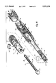
- FIG. 1 a side view of an injection device according to the invention
- FIG. 2 a longitudinal section through the injection device of FIG. 1 in its inactive position, or in other words after the conclusion of an injection;
- FIG. 3 a longitudinal section through the injection device of FIGS. 1 and 2 in its active position, but before a dose that is to be injected is set;
- FIG. 4 a longitudinal section analogous to FIG. 3, but after the setting of the dose to be injected;
- FIG. 5 a longitudinal section through the device of FIG. 4, but after the conclusion of the injection process
- FIG. 6 a perspective view of the parts of the device used for setting the dose, seen individually;
- FIG. 6A shows another embodiment of part c of FIG. 6
- FIG. 7 a perspective view of the parts of the device used for setting the dose, in the assembled state and in the position analogous to FIG. 2;
- FIG. 8 a perspective view analogous to FIG. 7, but in the position analogous to FIG. 4, or in other words when the dose to be injected is being set;
- FIG. 9 a longitudinal section through the part of the device used for setting the dose, on a enlarged scale.
- FIGS. 10-14 sections taken along the lines X--X through XIV--XIV of FIG. 9.
- proximal and distal are used in the usual way in medicine; that is, proximal means toward the patient and distal means away from the patient.
- FIG. 1 shows an injection device 10 according to the invention, seen in a side view and on a scale of approximately 1:1.
- Its left housing part 11 is made of transparent material and contains in its interior a cartridge 12, which typically is of glass and is filled with the liquid 13 to be injected, such as papaverin or insulin.
- this liquid is limited by a piston 14 of some suitable elastic material, typically rubber, that is displaceable in the axial direction. If this piston 14 is displaced to the left, then liquid is pressed out of the cartridge 12 and exits through an injection needle 15, also called a hollow needle.
- the distance by which the piston 14 is displaced to the left in an injection determines the quantity of liquid injected. The user can visually observe the location of the piston 14 through the housing part 11 and therefore knows how much injection liquid is still available.
- the cartridge 12 tapers at its left end, where it is provided with a metal cap 17 that holds a thin rubber membrane 16.
- the injection needle 15 is retained in a threaded cap 18, and when this cap is screwed onto a male thread on the proximal end of the housing part 11, the distal end of the needle 15 pierces the rubber membrane 16 and penetrates into the injection liquid 13.
- the needle 15 can thus be easily replaced by unscrewing the thread cap 18--so that a sterile needle can be available for each injection.
- the left housing part 11 is connected by detent connections 20, as shown, to a right housing part 21, which--like the left housing part 11--may be made of a suitable plastic, but in this case the plastic need not be transparent.
- the mechanism 19 for setting the quantity of liquid to be injected and for carrying out the actual injection process, that is, the process that follows the penetration of the tissue of the patient by the needle 15 and in which the liquid is injected into this tissue, are located in the housing part 21.
- a control member 23 is used, in the form of an actuation knob. As a comparison of FIG. 2 with FIG. 3 shows, this control member 23 can be displaced in an axial direction. It can also, in the dosage-setting position, hereinafter also called the active position, be rotated, as indicated by an arrow 24 in FIG. 3, in order to set the quantity of liquid to be injected.
- FIGS. 6-8 show the mechanism 19 and its parts in a perspective view, which is accordingly easier to understand.
- the mechanism 19 comprises only a few parts, which are typically inexpensively made as injection-molded parts from some suitable plastic material.
- a threaded spindle 29 Acting directly upon the piston 14 is the proximal end 28 of a threaded spindle 29 (FIG. 6, part a), which preferably has two opposed longitudinal grooves 30, 31 (FIG. 10) and which is provided on its outside with a coarse-pitch rectangular thread 32.
- the threaded spindle 29 is injection molded from plastic, and the two opposed longitudinal grooves 30, 31 prevent it from warping after being removed from the injection mold, or from becoming bent, which could interfere with its function.
- the threaded spindle 29 is inserted through an axial opening 33 of a guide member 34, (FIG. 6, part b) and it is guided longitudinally in this axial opening 33 by in a guide protrusion 36 that is provided there and runs in one of the longitudinal grooves 30 or 31 of the threaded spindle 29.
- the threaded spindle 29 is screwed into the female thread 35 of a threaded member 38 see FIG. 6, part c.
- the latter is pulled into an axial recess 40 (FIG. 9) of the guide member 34 and, once it has reached its terminal position, is secured against axial displacement relative to the guide member 34 by a locking member 43.
- the locking member 43 is introduced from the outside through an opening 44 (FIG. 6, part b) of the guide member 34 and with its inner end it engages an annular groove 45 on the proximal end of the threaded member 38.
- the threaded member 38 and the guide member 34 can be rotated relative to one another but cannot be displaced relative to one another, except for the unavoidable play in such arrangements.
- the threaded spindle 29 would also rotate with it.
- the guide member 34 in the active position is locked in a nonrotatable manner in the housing part 21, then the threaded spindle 29 cannot rotate relative to the housing part 21 but instead is forced into an axial motion.
- the rotation between the threaded member 38 and the guide member 34 is also limited, specifically by a detent arrangement having a detent pawl 48 on the guide member 34, which pawl engages a detent tooth system 49 on the threaded member 38.
- this detent arrangement 48, 49 is released by raising the detent pawl 48. It then--preferentially--enables only a counterclockwise rotation of the control member 23, looking at this control member from the distal side, but blocks against a clockwise rotation. Consequently, the threaded spindle 29 can be rotated only out of the threaded member 38, together with which it forms an adjustable-length plunger 29, 38, but cannot be rotated into the threaded member 38. This length adjustment of the plunger 29, 38 is possible, however, only if the guide member 34 at that time is secured against rotation in the housing part 21.
- FIG. 6A shows a variant of the threaded member 38 part c of FIG. 6.
- the female thread 35 is shown more clearly here.
- the detent tooth system 49' here is formed identically to that of FIGS. 9 and 11. It enables dosage setting in both directions; that is, if the patient has set the dose of his medicine too high, he can reverse the dosage setting again somewhat, which is not possible in the version of part c of FIG. 6).
- the cylindrical segment 50 adjoining the tooth system 49' in the distal direction preferably has a smaller diameter than the tooth system, as shown in FIGS. 6A and 9. This makes it easier to produce the threaded member 38 as an injection molded part. Parts 45 and 60, 61, 62 of FIG. 6A are identical with part c and therefore will not be described again.
- securing of the guide member 34 against rotation relative to the housing part 21 exists only in some of the possible axial positions of the mechanism 19; that is, the length adjustment is not possible in all positions.
- a system of external splines 55 is provided on the outside of the guide member 34 and on its distal end, and a corresponding system of internal splines 56 is associated with it in the interior of the housing part 21.
- FIG. 9 clearly shows, in the position after an injection, which can also be called the inactive position, the external tooth system 55 (on the guide member 34) is not in engagement with the internal tooth system 56 (in the interior of the housing part 21); that is, in this position, which is also shown in FIG. 2, a rotation of the control member 23 brings about only a rotation of the mechanism 19, including the threaded spindle and its proximal end 28, but not the unscrewing of the threaded spindle 29 out of the threaded member 38.
- This is important because people often unconsciously play with articles and, hence, there is a tendency to rotate this device and its parts, and because this is possible without danger in this inactive position, the setting of the device cannot be altered as a result.
- Adjusting the total length of the plunger 29, 38 in fact necessarily requires rotating the threaded member 38 relative to the guide member 34, which is possible only if the guide member 34 is restrained by the housing part 21. Yet this is not the case in the inactive position; that is, in the inactive position, setting of the injection dose is not possible.
- the threaded member 38 On its distal end region, the threaded member 38 is provided in the manner shown with a resiliently deflectable blocking member 60, which is formed on its distal side 61 as a blocking means and on its proximal side 62 with an incline; see in particular FIG. 9.
- a blocking means belt 65 in the interior of the distal end of the housing part 21 is associated with the blocking member 60 (FIG. 6, part c).
- This blocking belt 65 takes the form of a radially inwardly protruding annular bead which has an opening in the form of a longitudinal groove 66 only at one point, the cross-section shape of this groove being adapted to that of the blocking member 60. That is, only at the point of this longitudinal groove 66 can the blocking member 60 overcome the blocking belt 65, if the threaded member 38 is to be displaced out of its inactive position (FIG. 2) into its active position (FIGS. 3 and 4).
- the longitudinal groove 66 has still another function, however, because it guides the control member 23 until the control member has reached its active position, and only then enables setting of the dose. That is, as long as the blocking member 60 is located in the longitudinal groove 66, this groove prevents any rotation of the control member 23. This forces the patient to displace the control member 23 all the way into the active position, because only then is dose setting made possible.
- the blocking member 60 upon attainment of the active position, emerges from the longitudinal groove 66 and enters a frusto-conical recess 70 on the distal end of the blocking belts 65, the cone angle of which is adapted to the slope of the incline 62, so that the incline can rotate in the recess 70 and one can there, that is, after reaching the active position, set the dose by rotating the control member 23.
- the device has its zero position in this position, that is, once the blocking member 60 has left the longitudinal groove 66, and in this position, a symbol 71 (FIG. 1) provided on the control member 23 may for instance be located opposite the zero position of a scale (not shown) that is provided on the outside of the distal end region 72 of the housing part 21.
- this distal end region 72 is covered by the control member 23 and then is not visible.
- a marking 72' may additionally be provided on the housing part 21.
- the active position as shown in FIGS. 3 and 4, it is possible as in FIG. 4, by rotating the control member 23 in the direction of the rotational arrow 24, to adjust the proximal end 28 of the threaded spindle 29 in the direction of the arrow 74, that is, in the proximal direction.
- This rotation of the control member 23 in the direction of the rotational arrow 24 is preferentially possible only up to some maximum. For this reason---including when the maximum injection dose is being set---the proximal end 28 of the threaded spindle 29 keeps an adequate distance for safety from the piston 14.
- a stop 76 for the blocking member 60 may be provided on the inside of the segment 72 (of the housing part 21), and this stop 76 limits the dosage to a maximum of one rotation of the control member 23, or as needed to an even smaller angular travel, for instance a one-half rotation. This prevents overdosing with certainty.
- the arrangement can be simplified, because then the blocking member 60 and the longitudinal groove 66 can be dispensed with; but then the possibility of the stop 76 that prevents overdosage is not possible either. In that case, it is possible for the proximal end 28 of the threaded spindle 29 to be adjusted far enough that there is no longer an adequate safety distance from the piston 14. This possibility is therefore not so preferable.
- the control member 23 is secured to the distal end of the threaded member 38 by a snap connection.
- the threaded member 38 has a radial recess 80 for this purpose (FIG. 9), into which a radial protrusion 81 of a resilient axial extension 82 of the control member 23 protrudes from the inside.
- the control member 23 also has an annular axial extension 83 on the inside, which in the assembled state form-fittingly surrounds the distal end of the threaded member 38.
- the control member 23 accordingly merely has to be pressed onto the distal end of the threaded member 28, and then the radial protrusion 81 snaps into the recess 80 and brings about a firm connection between these parts. Securing of the housing part 11 to the housing part 21 is effected in a similar way by a snap connection that automatically arises when these housing parts 11, 21 are put together. This enables a very simple, inexpensive assembly.
- the injection device of FIG. 1 is produced by the manufacturer ready for use; that is, it comes to the user already loaded with a filled cartridge 12.
- the user secures a sterile needle 15 on the housing part 11 in the manner already described, puts the two markings 71, 72 (FIG. 1) opposite one another, and then pulls the actuation member 23 in the distal direction, as shown in FIG. 3.
- the blocking member 60 thereupon slides through the longitudinal groove 66, as also already described.
- FIG. 3 Only in the position shown in FIG. 3 is setting of the desired injection dose possible, and this is done by rotating the control member 23 to the point of the desired dose (arrow 24 in FIG. 4), whereupon the proximal end 28 of the threaded spindle 29 is displaced in the direction of the arrow 74 (FIG. 4), that is, in the direction toward the piston 14.
- Dose setting is possible because in the active position of FIGS. 3 and 4 the guide member 34 is not rotatable relative to the housing part 21, as has been described in detail above.
- FIG. 8 schematically shows how in this position the guide member 34, via its external tooth system 55, is in engagement with the internal tooth system 56 of the housing part 21, so that it cannot be rotated relative to the housing part 21.
- the patient then inserts the needle 15 and then presses on the control member 23 in the proximal direction (arrow 88 in FIG. 5), causing the piston 14 to be displaced in the proximal direction and causing liquid 13 to be injected through the needle 15 into the patient.
- This is indicated symbolically in FIG. 5 by the droplet 89.
- the blocking member 60 is resiliently deflected radially inward by the frustoconical segment 70 on the distal end of the blocking belt 65 and slides unhindered away along the blocking means belt 65. This is not possible in the opposite direction, because then the hook-shaped side 61 of the blocking member 60 rests against a steep shoulder 65', see FIG. 6, part d, complementary to it, on the proximal end of the blocking belt 65, which prevents an axial displacement there, except for the rotational position in which the blocking member 60 can slide through the longitudinal groove 66.
- the stop 76 (FIG. 14) prevents the control member 23 from being rotated by more than one rotation and thereby sets an upper limit to the adjustable dose.
- the stop 76 can also be selected as needed such that it enables a rotation of the control member 23 by only half a rotation, for instance.
- FIGS. 6-8 serve to explain the invention in a simple and easily understood manner. They do not match the views of FIGS. 1-5 and 9-14 in all points.
- the sectional views of FIGS. 2-5 and 9-14 show a functional device along with the dimensions and dimensional proportions to be observed for such a device.
- the device according to the invention is practical for the device according to the invention to be designed as a disposable device that is thrown away after the injection liquid 13 (in the container 12) has been used up.
- the possibility also exists, however, after one cartridge 12 has been used, of inserting a new cartridge and screwing the threaded spindle 29 all the way back into the threaded member 38 again.
- the form of the detent arrangement of FIG. 11 is recommended, which enables a rotation in both directions, while the form of the detent teeth 49 in part c, as shown in FIG. 6 enables a rotation in only a single direction.
Abstract
Description
Claims (32)
Priority Applications (1)
| Application Number | Priority Date | Filing Date | Title |
|---|---|---|---|
| US08/549,641 US5591136A (en) | 1991-04-15 | 1995-10-27 | Injection device |
Applications Claiming Priority (5)
| Application Number | Priority Date | Filing Date | Title |
|---|---|---|---|
| DE4112259.3 | 1991-04-15 | ||
| DE4112259A DE4112259A1 (en) | 1991-04-15 | 1991-04-15 | INJECTION DEVICE |
| PCT/EP1992/000831 WO1992018179A1 (en) | 1991-04-15 | 1992-04-13 | Injection device |
| US12256593A | 1993-09-30 | 1993-09-30 | |
| US08/549,641 US5591136A (en) | 1991-04-15 | 1995-10-27 | Injection device |
Related Parent Applications (1)
| Application Number | Title | Priority Date | Filing Date |
|---|---|---|---|
| US12256593A Continuation | 1991-04-15 | 1993-09-30 |
Publications (1)
| Publication Number | Publication Date |
|---|---|
| US5591136A true US5591136A (en) | 1997-01-07 |
Family
ID=6429618
Family Applications (1)
| Application Number | Title | Priority Date | Filing Date |
|---|---|---|---|
| US08/549,641 Expired - Lifetime US5591136A (en) | 1991-04-15 | 1995-10-27 | Injection device |
Country Status (6)
| Country | Link |
|---|---|
| US (1) | US5591136A (en) |
| EP (1) | EP0581788B1 (en) |
| JP (1) | JP2607817B2 (en) |
| AT (1) | ATE143610T1 (en) |
| DE (2) | DE4112259A1 (en) |
| WO (1) | WO1992018179A1 (en) |
Cited By (94)
| Publication number | Priority date | Publication date | Assignee | Title |
|---|---|---|---|---|
| US5843042A (en) * | 1996-11-06 | 1998-12-01 | Ren; Liang Chen | Oral medicine dispensing device having a metered syringe component and reservoir |
| US5938642A (en) * | 1995-03-07 | 1999-08-17 | Eli Lilly And Company | Multiple dose medication dispensing device |
| US6004298A (en) * | 1993-10-29 | 1999-12-21 | Pharmacia & Upjohn Aktiebolag | Injection devices |
| US6053893A (en) * | 1997-09-12 | 2000-04-25 | Disetronic Licensing Ag | Device for the dosed release of an injectable product |
| US6086567A (en) * | 1996-04-02 | 2000-07-11 | Disetronic Licensing Ag | Injection device |
| US6090080A (en) * | 1996-07-05 | 2000-07-18 | Disetronic Licensing Ag | Injection device for injection of liquid |
| US6106501A (en) * | 1995-11-09 | 2000-08-22 | Disetronic Licensing Ag | Injection device |
| US6183446B1 (en) | 1997-12-11 | 2001-02-06 | Disetronic Licensing Ag | Needle protection injection devices |
| US6258068B1 (en) | 1998-05-15 | 2001-07-10 | Disetronic Licensing Ag | Device for administering an injectable product |
| US6277101B1 (en) | 1996-04-02 | 2001-08-21 | Disetronic Licensing Ag | Injection device |
| US6280421B1 (en) | 1998-05-15 | 2001-08-28 | Disetronic Licensing Ag | Automatic injection device |
| US6290679B1 (en) | 1999-05-14 | 2001-09-18 | Disetronic Licensing Ag | Device for metered administration of an injectable product |
| US6413242B1 (en) | 1996-07-05 | 2002-07-02 | Disetronic Licensing Ag | Injection device for injection of liquid |
| US20030088216A1 (en) * | 2001-10-03 | 2003-05-08 | Daniel Py | Syringe and reconstitution syringe |
| US20030089743A1 (en) * | 2001-10-16 | 2003-05-15 | Daniel Py | Dispenser with sealed chamber and one-way valve for providing metered amounts of substances |
| US6673049B2 (en) | 2001-02-15 | 2004-01-06 | Disetronic Licensing Ag | Injection device for injecting fluid |
| WO2004002556A1 (en) * | 2002-06-28 | 2004-01-08 | Tecpharma Licensing Ag | Product distribution device with rapid piston rod resetting |
| US20040059299A1 (en) * | 2000-06-16 | 2004-03-25 | Moller Claus Schmidt | Injection device |
| US20040097883A1 (en) * | 2000-10-09 | 2004-05-20 | Roe Michael Joseph | Pen device for administration of parathyroid hormone |
| US20040127858A1 (en) * | 2002-10-01 | 2004-07-01 | Becton, Dickinson And Company | Medication delivery pen |
| US6793660B2 (en) | 2001-08-20 | 2004-09-21 | Synthes (U.S.A.) | Threaded syringe for delivery of a bone substitute material |
| US20040186442A1 (en) * | 2001-07-30 | 2004-09-23 | Roney Graf | Reservoir module comprising a piston rod |
| US20040186431A1 (en) * | 2001-07-30 | 2004-09-23 | Roney Graf | Administering apparatus comprising a dosing device |
| US20040236285A1 (en) * | 2001-07-16 | 2004-11-25 | Fisher Mark James | Medication dispensing apparatus configured for rotate to prime and pull/push to inject functionality |
| US20050004529A1 (en) * | 2003-04-10 | 2005-01-06 | Veasey Robert Frederick | Drive mechanisms suitable for use in drug delivery devices |
| US20050033224A1 (en) * | 2001-12-21 | 2005-02-10 | Fritz Kirchhofer | Injection apparatus with an end position-blocked dosage setting member |
| US20050055011A1 (en) * | 2001-01-05 | 2005-03-10 | Christian Enggaard | Automatic injection device with reset feature |
| US20050089358A1 (en) * | 2003-07-17 | 2005-04-28 | Daniel Py | Piston-type dispenser with one-way valve for storing and dispensing metered amounts of substances |
| US20050189379A1 (en) * | 2004-01-27 | 2005-09-01 | Daniel Py | Dispenser having variable-volume storage chamber and depressible one-way valve assembly for dispensing creams and other substances |
| US7066909B1 (en) | 1997-04-23 | 2006-06-27 | Disetronic Licensing Ag | Propelling device for a piston in a container containing a liquid medicament |
| US20060178167A1 (en) * | 1997-04-24 | 2006-08-10 | Ntt Mobile Communications Network, Inc. | Method and system for mobile communications |
| WO2006089767A1 (en) * | 2005-02-28 | 2006-08-31 | Novo Nordisk A/S | Dose setting mechanism for an injection device capable of presetting a maximum dose |
| US20060258988A1 (en) * | 2003-11-03 | 2006-11-16 | Joachim Keitel | Injection device |
| US20070093761A1 (en) * | 2003-03-03 | 2007-04-26 | Dca Design International Ltd. | Drive mechanisms suitable for use in drug delivery devices |
| US20070112310A1 (en) * | 2003-07-31 | 2007-05-17 | Sid Technologies Llc | Injecting apparatus |
| US20070162063A1 (en) * | 2006-01-12 | 2007-07-12 | Owen Mumford, Ltd. | Lancet firing device |
| US20070167921A1 (en) * | 2004-04-23 | 2007-07-19 | Stefan Burren | Injection Device with Dose Metering Mechanism with Multiple Anti-Rotation Locking System |
| US20070191784A1 (en) * | 2004-03-30 | 2007-08-16 | Jacobs Alexander T | Medication dispensing apparatus with gear set having drive member accommodating opening |
| US20070197976A1 (en) * | 2004-03-30 | 2007-08-23 | Jacobs Alexander T | Medication dispensing apparatus with spring-driven locking feature enabled by administration of final dose |
| US20080051713A1 (en) * | 2004-12-31 | 2008-02-28 | Philippe Kohlbrenner | Device for the dosed administration of a fluid product comprising a torsion spring drive |
| US20080119796A1 (en) * | 2001-07-30 | 2008-05-22 | Tecpharma Licensing Ag | Reservoir module comprising a piston rod |
| US20080135130A1 (en) * | 2005-08-01 | 2008-06-12 | Daniel Py | Dispenser with Sealed Chamber, One-Way Valve and Needle Penetrable and Laser Resealable Stopper |
| US20080142112A1 (en) * | 2003-05-12 | 2008-06-19 | Daniel Py | Dispenser and Apparatus and Method of Filling a Dispenser |
| US20080208142A1 (en) * | 2005-02-28 | 2008-08-28 | Novo Nordisk A/S | Dose Setting Mechanism for an Injection Device |
| US20090043264A1 (en) * | 2005-04-24 | 2009-02-12 | Novo Nordisk A/S | Injection Device |
| US20090054839A1 (en) * | 2004-10-21 | 2009-02-26 | Novo Nordisk A/S | Injection device with torsion spring and rotatable display |
| US20090069742A1 (en) * | 2006-03-20 | 2009-03-12 | Andre Larsen | Electronic Module for Mechanical Medication Delivery Devices |
| DE102007052013A1 (en) * | 2007-10-31 | 2009-05-07 | Tecpharma Licensing Ag | Dosing system for an injection device and injection device |
| US20090209920A1 (en) * | 2006-05-18 | 2009-08-20 | Novo Nordisk A/S | Injection Device with Mode Locking Means |
| US20090264828A1 (en) * | 2006-09-14 | 2009-10-22 | Christoph Dette | Drug Delivery Device Dose Setting Mechanism |
| US20090287345A1 (en) * | 2006-05-16 | 2009-11-19 | Rorze Corporation | Shuttle type conveying device, microplate feeding and collecting device, pickup device for microplate, cassette for microplate, and shelf for receiving microplate |
| US20100004560A1 (en) * | 2001-10-22 | 2010-01-07 | Owen Mumford, Ltd. | Confuser crown skin pricker |
| US20100022964A1 (en) * | 2006-05-16 | 2010-01-28 | Novo Nordisk A/S | Gearing Mechanism for an Injection Device |
| US20100056985A1 (en) * | 2008-08-27 | 2010-03-04 | Boston Scientific Scimed, Inc. | Electroactive polymer activation system for a medical device |
| US20100069845A1 (en) * | 2005-12-02 | 2010-03-18 | Owen Mumford, Ltd. | Injection method and apparatus |
| US20100114025A1 (en) * | 2007-03-23 | 2010-05-06 | Novo Nordisk A/S | Injection device comprising a locking nut |
| US20100114037A1 (en) * | 2007-04-23 | 2010-05-06 | Ulrich Moser | Reversely rotatable dose setting mechanism for an injection device |
| US20100145275A1 (en) * | 2006-11-16 | 2010-06-10 | Becton Dickinson France S.A.S. | Device for Automatic Delivery of Successive Doses of Product |
| WO2010097125A1 (en) | 2009-02-26 | 2010-09-02 | Shl Group Ab | Dose setting mechanism |
| USRE41956E1 (en) | 1999-09-16 | 2010-11-23 | Novo Nordisk A/S | Dose setting limiter |
| WO2010139630A1 (en) * | 2009-06-01 | 2010-12-09 | Sanofi-Aventis Deutschland Gmbh | Drug delivery dose setting mechanism with variable maximum dose |
| US20100324493A1 (en) * | 2009-06-01 | 2010-12-23 | Sanofi-Aventis Deutschland Gmbh | Inner housing for a drug delivery device |
| US20100324494A1 (en) * | 2009-06-01 | 2010-12-23 | Sanofi-Aventis Deutschland Gmbh | Drug delivery device last dose lock-out mechanism |
| US20100324496A1 (en) * | 2009-06-01 | 2010-12-23 | Sanofi-Aventis Deutschland Gmbh | Dose setting mechanism for priming a drug delivery device |
| US20100324528A1 (en) * | 2009-06-01 | 2010-12-23 | Sanofi-Aventis Deutschland Gmbh | Dose setting mechanism for priming a drug delivery device |
| US20100324495A1 (en) * | 2009-06-01 | 2010-12-23 | Sanofi-Aventis Deutschland Gmbh | Resettable drug delivery device |
| US20100324497A1 (en) * | 2009-06-01 | 2010-12-23 | Sanofi-Aventis Deutschland Gmbh | Biasing mechanism for a drug delivery device |
| US20100331789A1 (en) * | 2009-06-01 | 2010-12-30 | Sanofi-Aventis Deutschland Gmbh | Dose setting mechanism for priming a drug delivery device |
| US20100331790A1 (en) * | 2009-06-01 | 2010-12-30 | Sanofi-Aventis Deutschland Gmbh | Spindle for a drug delivery device |
| US20100331791A1 (en) * | 2009-06-01 | 2010-12-30 | Sanofi-Aventis Deutschland Gmbh | Drug delivery device with dose dial sleeve rotational stop |
| US20100331792A1 (en) * | 2009-06-01 | 2010-12-30 | Sanofi-Aventis Deutschland Gmbh | Drug delivery device inner housing having helical spline |
| US20100331786A1 (en) * | 2009-06-01 | 2010-12-30 | Sanofi-Aventis Deutschland Gmbh | Spindle and bearing combination and drug delivery device |
| US20100331788A1 (en) * | 2009-06-01 | 2010-12-30 | Sanofi-Aventis Deutschland Gmbh | Resettable drug delivery device |
| US20100331806A1 (en) * | 2009-06-01 | 2010-12-30 | Sanofi-Aventis Deutschland Gmbh | Drive mechanism for a drug delivery device |
| US20110004191A1 (en) * | 2009-06-01 | 2011-01-06 | Sanofi-Aventis Deutschland Gmbh | Dosing mechanism for a drug deliver device |
| US20110015576A1 (en) * | 2009-06-01 | 2011-01-20 | Sanofi-Aventis Deutschland Gmbh | Medicament identification system for multi-dose injection devices |
| US8298194B2 (en) | 2006-03-10 | 2012-10-30 | Novo Nordisk A/S | Injection device and a method of changing a cartridge in the device |
| USRE43834E1 (en) | 1998-01-20 | 2012-11-27 | Novo Nordisk A/S | Injection syringe |
| US20130006259A1 (en) * | 2010-04-08 | 2013-01-03 | Demas Sanger | Detailed description of exemplary embodiments |
| US8361036B2 (en) | 2006-03-10 | 2013-01-29 | Novo Nordisk A/S | Injection device having a gearing arrangement |
| US20130197446A1 (en) * | 2010-10-11 | 2013-08-01 | Shl Group Ab | Medicament Delivery Device |
| US8568366B2 (en) | 2001-07-30 | 2013-10-29 | Tecpharma Licensing Ag | Reservoir module for an administering apparatus |
| US8998855B2 (en) | 2008-11-17 | 2015-04-07 | Owen Mumford, Ltd. | Syringe and needle cover remover |
| US9265893B2 (en) | 2007-02-05 | 2016-02-23 | Novo Nordisk A/S | Injection button |
| US20160089502A1 (en) * | 2012-01-17 | 2016-03-31 | Dr. Py Institute Llc | Multiple dose syringe and method |
| US9408455B2 (en) | 2002-08-13 | 2016-08-09 | MedInstill Development, LLC | Container and valve assembly for storing and dispensing substances, and related method |
| US9533106B2 (en) | 2011-12-29 | 2017-01-03 | Novo Nordisk A/S | Torsion-spring based wind-up auto injector pen with dial-up/dial-down mechanism |
| USRE46363E1 (en) | 2004-10-21 | 2017-04-11 | Novo Nordisk A/S | Dial-down mechanism for wind-up pen |
| US9956351B2 (en) | 2009-11-20 | 2018-05-01 | Becton, Dickinson And Company | Injection device without a gearing |
| CN109283653A (en) * | 2018-11-24 | 2019-01-29 | 中国科学院长春光学精密机械与物理研究所 | Adhesive dispenser is given for space camera reflecting mirror |
| WO2020249807A1 (en) * | 2019-06-14 | 2020-12-17 | Owen Mumford Limited | Improved drug delivery device having a plunger with adjustable length |
| US20210153994A1 (en) * | 2019-11-27 | 2021-05-27 | The Procter & Gamble Company | Dosing Indicator |
| US11318191B2 (en) | 2020-02-18 | 2022-05-03 | Novo Nordisk A/S | GLP-1 compositions and uses thereof |
| US11752198B2 (en) | 2017-08-24 | 2023-09-12 | Novo Nordisk A/S | GLP-1 compositions and uses thereof |
Families Citing this family (9)
| Publication number | Priority date | Publication date | Assignee | Title |
|---|---|---|---|---|
| US5545147A (en) * | 1992-10-20 | 1996-08-13 | Eli Lilly And Company | Anti-backup improvement for hypodermic syringes |
| US5584815A (en) * | 1993-04-02 | 1996-12-17 | Eli Lilly And Company | Multi-cartridge medication injection device |
| ZA941881B (en) * | 1993-04-02 | 1995-09-18 | Lilly Co Eli | Manifold medication injection apparatus and method |
| JP3120747B2 (en) * | 1997-02-12 | 2000-12-25 | 富士電機株式会社 | Syringe pump clutch mechanism |
| DE19723647C1 (en) | 1997-06-05 | 1998-12-24 | Disetronic Licensing Ag | Fluid dosing unit indicator for e.g. insulin or for pipetting laboratory fluids |
| DE19730999C1 (en) * | 1997-07-18 | 1998-12-10 | Disetronic Licensing Ag | Injection pen dosing selected volume of fluid, especially insulin |
| GB0306642D0 (en) * | 2003-03-22 | 2003-04-30 | Dca Design Int Ltd | Improvements in and relating to an injector for a medical product |
| DE102005022532A1 (en) * | 2005-05-17 | 2006-11-23 | Tecpharma Licensing Ag | Delivery device with forced priming |
| GB2433032A (en) † | 2005-12-08 | 2007-06-13 | Owen Mumford Ltd | Syringe with dose adjustment means |
Citations (11)
| Publication number | Priority date | Publication date | Assignee | Title |
|---|---|---|---|---|
| EP0058536A1 (en) * | 1981-02-12 | 1982-08-25 | Robert Charles Turner | Dose metering plunger devices for use with syringes |
| US4592745A (en) * | 1984-02-29 | 1986-06-03 | Novo Industri A/S | Dispenser |
| US4710179A (en) * | 1986-10-27 | 1987-12-01 | Habley Medical Technology Corporation | Snap-on vernier syringe |
| EP0268191A2 (en) * | 1986-11-14 | 1988-05-25 | WILHELM HASELMEIER GMBH & CO. | Injection device |
| WO1988008725A1 (en) * | 1987-05-08 | 1988-11-17 | Wilhelm Haselmeier Gmbh + Co. | Injection device with a loading element and a second setting element |
| US4865591A (en) * | 1987-06-12 | 1989-09-12 | Hypoguard (Uk) Limited | Measured dose dispensing device |
| US4973318A (en) * | 1988-02-10 | 1990-11-27 | D.C.P. Af 1988 A/S | Disposable syringe |
| US5104380A (en) * | 1988-04-18 | 1992-04-14 | Robert Charles Turner | Syringe with dose metering device |
| US5112317A (en) * | 1988-01-22 | 1992-05-12 | Nosta Ag | Injection device |
| US5226896A (en) * | 1990-04-04 | 1993-07-13 | Eli Lilly And Company | Dose indicating injection pen |
| US5308340A (en) * | 1989-06-05 | 1994-05-03 | Eli Lilly And Company | Multiple dose injection pen |
Family Cites Families (1)
| Publication number | Priority date | Publication date | Assignee | Title |
|---|---|---|---|---|
| DE3715340C2 (en) * | 1987-05-08 | 1995-10-19 | Haselmeier Wilhelm Fa | Injection device |
-
1991
- 1991-04-15 DE DE4112259A patent/DE4112259A1/en not_active Ceased
-
1992
- 1992-04-13 WO PCT/EP1992/000831 patent/WO1992018179A1/en active IP Right Grant
- 1992-04-13 EP EP92907667A patent/EP0581788B1/en not_active Expired - Lifetime
- 1992-04-13 JP JP4507658A patent/JP2607817B2/en not_active Expired - Lifetime
- 1992-04-13 AT AT92907667T patent/ATE143610T1/en not_active IP Right Cessation
- 1992-04-13 DE DE59207292T patent/DE59207292D1/en not_active Expired - Lifetime
-
1995
- 1995-10-27 US US08/549,641 patent/US5591136A/en not_active Expired - Lifetime
Patent Citations (14)
| Publication number | Priority date | Publication date | Assignee | Title |
|---|---|---|---|---|
| EP0058536A1 (en) * | 1981-02-12 | 1982-08-25 | Robert Charles Turner | Dose metering plunger devices for use with syringes |
| US4592745A (en) * | 1984-02-29 | 1986-06-03 | Novo Industri A/S | Dispenser |
| US4710179A (en) * | 1986-10-27 | 1987-12-01 | Habley Medical Technology Corporation | Snap-on vernier syringe |
| EP0265876A2 (en) * | 1986-10-27 | 1988-05-04 | Habley Medical Technology Corporation | Snap-on vernier syringe |
| EP0268191A2 (en) * | 1986-11-14 | 1988-05-25 | WILHELM HASELMEIER GMBH & CO. | Injection device |
| US5114406A (en) * | 1986-11-14 | 1992-05-19 | Wilhelm Haselmeier Gmbh & Co. | Injection device for injection, especially self-administered injection, of medicament, including mechanisms for nulling and for selecting dosage, especially for use with multi-dose ampules |
| US5092842A (en) * | 1987-05-08 | 1992-03-03 | Wilhelm Haselmeier Gmbh & Co. | Injection device with a cocking element and a second setting element |
| WO1988008725A1 (en) * | 1987-05-08 | 1988-11-17 | Wilhelm Haselmeier Gmbh + Co. | Injection device with a loading element and a second setting element |
| US4865591A (en) * | 1987-06-12 | 1989-09-12 | Hypoguard (Uk) Limited | Measured dose dispensing device |
| US5112317A (en) * | 1988-01-22 | 1992-05-12 | Nosta Ag | Injection device |
| US4973318A (en) * | 1988-02-10 | 1990-11-27 | D.C.P. Af 1988 A/S | Disposable syringe |
| US5104380A (en) * | 1988-04-18 | 1992-04-14 | Robert Charles Turner | Syringe with dose metering device |
| US5308340A (en) * | 1989-06-05 | 1994-05-03 | Eli Lilly And Company | Multiple dose injection pen |
| US5226896A (en) * | 1990-04-04 | 1993-07-13 | Eli Lilly And Company | Dose indicating injection pen |
Cited By (284)
| Publication number | Priority date | Publication date | Assignee | Title |
|---|---|---|---|---|
| US6004298A (en) * | 1993-10-29 | 1999-12-21 | Pharmacia & Upjohn Aktiebolag | Injection devices |
| US5938642A (en) * | 1995-03-07 | 1999-08-17 | Eli Lilly And Company | Multiple dose medication dispensing device |
| US6001089A (en) * | 1995-03-07 | 1999-12-14 | Eli Lilly And Company | Multiple dose medication dispensing method |
| US6221046B1 (en) * | 1995-03-07 | 2001-04-24 | Eli Lilly And Company | Recyclable medication dispensing device |
| US6106501A (en) * | 1995-11-09 | 2000-08-22 | Disetronic Licensing Ag | Injection device |
| US6383167B2 (en) | 1996-04-02 | 2002-05-07 | Disetronic Licensing Ag | Injection device |
| US6086567A (en) * | 1996-04-02 | 2000-07-11 | Disetronic Licensing Ag | Injection device |
| US6277101B1 (en) | 1996-04-02 | 2001-08-21 | Disetronic Licensing Ag | Injection device |
| US6090080A (en) * | 1996-07-05 | 2000-07-18 | Disetronic Licensing Ag | Injection device for injection of liquid |
| US6413242B1 (en) | 1996-07-05 | 2002-07-02 | Disetronic Licensing Ag | Injection device for injection of liquid |
| US5843042A (en) * | 1996-11-06 | 1998-12-01 | Ren; Liang Chen | Oral medicine dispensing device having a metered syringe component and reservoir |
| US7066909B1 (en) | 1997-04-23 | 2006-06-27 | Disetronic Licensing Ag | Propelling device for a piston in a container containing a liquid medicament |
| US20070298804A1 (en) * | 1997-04-24 | 2007-12-27 | Ntt Mobile Communications Network, Inc. | Method and system for mobile communications |
| US7907730B2 (en) | 1997-04-24 | 2011-03-15 | Ntt Docomo, Inc. | Method and system for mobile communications |
| US20090149182A1 (en) * | 1997-04-24 | 2009-06-11 | Ntt Mobile Communications Network, Inc. | Method and system for mobile communications |
| US20080108356A1 (en) * | 1997-04-24 | 2008-05-08 | Ntt Mobile Communications Network, Inc. | Method and system for mobile communications |
| US7383045B2 (en) | 1997-04-24 | 2008-06-03 | Ntt Mobile Communications Network, Inc. | Method and system for mobile communications |
| US20090149181A1 (en) * | 1997-04-24 | 2009-06-11 | Ntt Mobile Communications Network, Inc. | Method and system for mobile communications |
| US20060251038A1 (en) * | 1997-04-24 | 2006-11-09 | Ntt Mobile Communications Network, Inc | Method and system for mobile communications |
| US20090154702A1 (en) * | 1997-04-24 | 2009-06-18 | Ntt Mobile Communications Network, Inc. | Method and system for mobile communications |
| US20060199578A1 (en) * | 1997-04-24 | 2006-09-07 | Ntt Mobile Communications Network, Inc. | Method and system for mobile communications |
| US20090191924A1 (en) * | 1997-04-24 | 2009-07-30 | Ntt Mobile Communications Network, Inc. | Method and System for Mobile Communications |
| US7953414B2 (en) | 1997-04-24 | 2011-05-31 | Ntt Docomo | Method and system for mobile communications |
| US20090197646A1 (en) * | 1997-04-24 | 2009-08-06 | Ntt Mobile Communications Network, Inc. | Method and system for mobile communications |
| US7577435B2 (en) | 1997-04-24 | 2009-08-18 | Ntt Mobile Communications Network, Inc. | Method and system for mobile communications |
| US8185158B2 (en) | 1997-04-24 | 2012-05-22 | Ntt Mobile Communications Network, Inc. | Method and system for mobile communications |
| US7630716B2 (en) | 1997-04-24 | 2009-12-08 | Ntt Docomo, Inc. | Method and system for mobile communications |
| US20090141687A1 (en) * | 1997-04-24 | 2009-06-04 | Ntt Mobile Communications Network, Inc. | Method and system for mobile communications |
| US8259675B2 (en) | 1997-04-24 | 2012-09-04 | Ntt Docomo, Inc. | Method and system for mobile communications |
| US7236787B1 (en) | 1997-04-24 | 2007-06-26 | Ntt Mobile Communications Network, Inc. | Method and system for mobile communications |
| US7664507B2 (en) | 1997-04-24 | 2010-02-16 | Ntt Docomo, Inc. | Method and system for mobile communications |
| US8275133B2 (en) | 1997-04-24 | 2012-09-25 | Ntt Docomo, Inc. | Method and system for mobile communications |
| US8542835B2 (en) | 1997-04-24 | 2013-09-24 | Ntt Docomo, Inc. | Method and system for mobile communications |
| US20060194583A1 (en) * | 1997-04-24 | 2006-08-31 | Ntt Mobile Communications Network, Inc. | Method and system for mobile communications |
| US20060264207A1 (en) * | 1997-04-24 | 2006-11-23 | Ntt Mobile Communications Network, Inc. | Method and system for mobile communications |
| US7792531B2 (en) | 1997-04-24 | 2010-09-07 | Ntt Docomo, Inc. | Method and system for mobile communications |
| US8331935B2 (en) | 1997-04-24 | 2012-12-11 | Ntt Docomo, Inc. | Method and system for mobile communications |
| US20060178167A1 (en) * | 1997-04-24 | 2006-08-10 | Ntt Mobile Communications Network, Inc. | Method and system for mobile communications |
| US6053893A (en) * | 1997-09-12 | 2000-04-25 | Disetronic Licensing Ag | Device for the dosed release of an injectable product |
| US6183446B1 (en) | 1997-12-11 | 2001-02-06 | Disetronic Licensing Ag | Needle protection injection devices |
| USRE43834E1 (en) | 1998-01-20 | 2012-11-27 | Novo Nordisk A/S | Injection syringe |
| US7931626B2 (en) | 1998-05-15 | 2011-04-26 | Tecpharma Licensing Ag | Device for administering an injectable product |
| US6620137B2 (en) | 1998-05-15 | 2003-09-16 | Disetronic Licensing Ag | Automatic injection device |
| US6258068B1 (en) | 1998-05-15 | 2001-07-10 | Disetronic Licensing Ag | Device for administering an injectable product |
| US6280421B1 (en) | 1998-05-15 | 2001-08-28 | Disetronic Licensing Ag | Automatic injection device |
| US20010044847A1 (en) * | 1998-05-15 | 2001-11-22 | Fritz Kirchhofer | Device for administering an injectable product |
| US6485470B2 (en) | 1998-05-15 | 2002-11-26 | Disetronic Licensing Ag | Device for metered administration of an injectable product |
| US7128728B2 (en) | 1998-05-15 | 2006-10-31 | Tecpharma Licensing Ag | Device for administering an injectable product |
| US7931625B2 (en) | 1998-05-15 | 2011-04-26 | Tecpharma Licensing Ag | Device for administering an injectable product |
| US20080021410A1 (en) * | 1998-05-15 | 2008-01-24 | Fritz Kirchhofer | Device for administering an injectable product |
| US20080021397A1 (en) * | 1998-05-15 | 2008-01-24 | Fritz Kirchhofer | Device for administering an injectable product |
| US6290679B1 (en) | 1999-05-14 | 2001-09-18 | Disetronic Licensing Ag | Device for metered administration of an injectable product |
| USRE41956E1 (en) | 1999-09-16 | 2010-11-23 | Novo Nordisk A/S | Dose setting limiter |
| US8267899B2 (en) | 2000-06-16 | 2012-09-18 | Novo Nordisk A/S | Injection device |
| US8206361B2 (en) | 2000-06-16 | 2012-06-26 | Novo Nordisk A/S | Injection device |
| US10245383B2 (en) | 2000-06-16 | 2019-04-02 | Novo Nordisk A/S | Injection device |
| US8202256B2 (en) | 2000-06-16 | 2012-06-19 | Novo Nordisk A/S | Injection device |
| US20080281275A1 (en) * | 2000-06-16 | 2008-11-13 | Novo Nordisk A/S | Injection Device |
| US20070244445A1 (en) * | 2000-06-16 | 2007-10-18 | Novo Nordisk A/S | Injection Device |
| US20040059299A1 (en) * | 2000-06-16 | 2004-03-25 | Moller Claus Schmidt | Injection device |
| US8333739B2 (en) | 2000-06-16 | 2012-12-18 | Novo Nordisk A/S | Injection device |
| US7241278B2 (en) | 2000-06-16 | 2007-07-10 | Novo Nordisk A/S | Injection device |
| US9022991B2 (en) | 2000-06-16 | 2015-05-05 | Novo Nordisk A/S | Injection device |
| US20050209570A1 (en) * | 2000-06-16 | 2005-09-22 | Novo Nordisk A/S | Injection device |
| US20040097883A1 (en) * | 2000-10-09 | 2004-05-20 | Roe Michael Joseph | Pen device for administration of parathyroid hormone |
| US8672898B2 (en) | 2001-01-05 | 2014-03-18 | Novo Nordisk A/S | Automatic injection device with reset feature |
| US20050055011A1 (en) * | 2001-01-05 | 2005-03-10 | Christian Enggaard | Automatic injection device with reset feature |
| US9486588B2 (en) | 2001-01-05 | 2016-11-08 | Novo Nordisk A/S | Automatic injection device with reset feature |
| US6673049B2 (en) | 2001-02-15 | 2004-01-06 | Disetronic Licensing Ag | Injection device for injecting fluid |
| US20070142789A1 (en) * | 2001-07-16 | 2007-06-21 | Fisher Mark J | Medication dispensing apparatus configured for rotate to prime and pull/push to inject functionality |
| US7704237B2 (en) | 2001-07-16 | 2010-04-27 | Eli Lilly And Company | Medication dispensing apparatus configured for rotate to prime and pull/push to inject functionality |
| US20040236285A1 (en) * | 2001-07-16 | 2004-11-25 | Fisher Mark James | Medication dispensing apparatus configured for rotate to prime and pull/push to inject functionality |
| US8939944B2 (en) | 2001-07-30 | 2015-01-27 | Tecpharma Licensing Ag | Reservoir module comprising a piston rod |
| US8007476B2 (en) | 2001-07-30 | 2011-08-30 | Tecpharma Licensing Ag | Administering apparatus comprising a dosing device |
| US20040186431A1 (en) * | 2001-07-30 | 2004-09-23 | Roney Graf | Administering apparatus comprising a dosing device |
| US20080195051A1 (en) * | 2001-07-30 | 2008-08-14 | Tecpharma Licensing Ag | Latching Block for Connecting Casing Sections of an Administering Apparatus |
| US8568366B2 (en) | 2001-07-30 | 2013-10-29 | Tecpharma Licensing Ag | Reservoir module for an administering apparatus |
| US20040186442A1 (en) * | 2001-07-30 | 2004-09-23 | Roney Graf | Reservoir module comprising a piston rod |
| US9205189B2 (en) | 2001-07-30 | 2015-12-08 | Tecpharma Licensing Ag | Reservoir module comprising a piston rod |
| US20070276341A1 (en) * | 2001-07-30 | 2007-11-29 | Roney Graf | Reservoir module comprising a piston rod |
| US7628773B2 (en) | 2001-07-30 | 2009-12-08 | Tecpharma Licensing Ag | Reservoir module comprising a piston rod |
| US20080119796A1 (en) * | 2001-07-30 | 2008-05-22 | Tecpharma Licensing Ag | Reservoir module comprising a piston rod |
| US6793660B2 (en) | 2001-08-20 | 2004-09-21 | Synthes (U.S.A.) | Threaded syringe for delivery of a bone substitute material |
| US20100276035A1 (en) * | 2001-10-03 | 2010-11-04 | Daniel Py | Device with penetrable and resealable portion |
| US7779609B2 (en) | 2001-10-03 | 2010-08-24 | Medical Instill Technologies, Inc. | Method of filling a device |
| US20070156102A1 (en) * | 2001-10-03 | 2007-07-05 | Daniel Py | Syringe and reconstitution syringe |
| US7186241B2 (en) | 2001-10-03 | 2007-03-06 | Medical Instill Technologies, Inc. | Syringe with needle penetrable and laser resealable stopper |
| US20030088216A1 (en) * | 2001-10-03 | 2003-05-08 | Daniel Py | Syringe and reconstitution syringe |
| US20050263543A1 (en) * | 2001-10-16 | 2005-12-01 | Daniel Py | Dispenser with sealed chamber, one-way valve and needle penetrable and laser resealable stopper |
| US8220507B2 (en) | 2001-10-16 | 2012-07-17 | Medical Instill Technologies, Inc. | Dispenser and method for storing and dispensing sterile product |
| US9630755B2 (en) | 2001-10-16 | 2017-04-25 | Medinstill Development Llc | Dispenser and method for storing and dispensing sterile product |
| US7290573B2 (en) | 2001-10-16 | 2007-11-06 | Medical Instill Technologies, Inc. | Dispenser with sealed chamber, one-way valve and needle penetrable and laser resealable stopper |
| US20030089743A1 (en) * | 2001-10-16 | 2003-05-15 | Daniel Py | Dispenser with sealed chamber and one-way valve for providing metered amounts of substances |
| US20100004560A1 (en) * | 2001-10-22 | 2010-01-07 | Owen Mumford, Ltd. | Confuser crown skin pricker |
| US20050033224A1 (en) * | 2001-12-21 | 2005-02-10 | Fritz Kirchhofer | Injection apparatus with an end position-blocked dosage setting member |
| US7828779B2 (en) | 2001-12-21 | 2010-11-09 | Tecpharma Licensing Ag | Injection apparatus with an end position-blocked dosage setting member |
| US20090137967A1 (en) * | 2002-06-28 | 2009-05-28 | Edgar Hommann | Product delivery device with rapid piston rod setting |
| US7842016B2 (en) | 2002-06-28 | 2010-11-30 | Tecpharma Licensing Ag | Product delivery device with rapid piston rod setting |
| WO2004002556A1 (en) * | 2002-06-28 | 2004-01-08 | Tecpharma Licensing Ag | Product distribution device with rapid piston rod resetting |
| US7445613B2 (en) | 2002-06-28 | 2008-11-04 | Tecpharma Licensing Ag | Product delivery device with rapid piston rod setting |
| DE10229138B4 (en) * | 2002-06-28 | 2008-01-31 | Tecpharma Licensing Ag | Product diverter with piston rod emergency reset |
| US9408455B2 (en) | 2002-08-13 | 2016-08-09 | MedInstill Development, LLC | Container and valve assembly for storing and dispensing substances, and related method |
| US20040127858A1 (en) * | 2002-10-01 | 2004-07-01 | Becton, Dickinson And Company | Medication delivery pen |
| US7169132B2 (en) * | 2002-10-01 | 2007-01-30 | Becton, Dickinson And Company | Medication delivery pen |
| US20140316347A1 (en) * | 2003-03-03 | 2014-10-23 | Sanofi-Aventis Deutschland Gmbh | Drive mechanisms suitable for use in drug delivery devices |
| US11554217B2 (en) | 2003-03-03 | 2023-01-17 | Sanofi-Aventis Deutschland Gmbh | Drive mechanisms suitable for use in drug delivery devices |
| US20070093761A1 (en) * | 2003-03-03 | 2007-04-26 | Dca Design International Ltd. | Drive mechanisms suitable for use in drug delivery devices |
| US20140316345A1 (en) * | 2003-03-03 | 2014-10-23 | Sanofi-Aventis Deutschland Gmbh | Drive mechanisms suitable for use in drug delivery devices |
| US20140316346A1 (en) * | 2003-03-03 | 2014-10-23 | Sanofi-Aventis Deutschland Gmbh | Drive mechanisms suitable for use in drug delivery devices |
| US20140316344A1 (en) * | 2003-03-03 | 2014-10-23 | Sanofi-Aventis Deutschland Gmbh | Relating to drive mechanisms suitable for use in drug delivery devices |
| US10729855B2 (en) | 2003-03-03 | 2020-08-04 | Sanofi-Aventis Deutschland Gmbh | Drive mechanisms suitable for use in drug delivery devices |
| US8556864B2 (en) | 2003-03-03 | 2013-10-15 | Sanofi-Aventis Deutschland Gmbh | Drive mechanisms suitable for use in drug delivery devices |
| US9011391B2 (en) | 2003-03-03 | 2015-04-21 | Sanofi-Aventis Deutschland Gmbh | Pen-type injector |
| US10653841B2 (en) | 2003-03-03 | 2020-05-19 | Sanofi-Aventis Deutschland Gmbh | Drive mechanisms suitable for use in drug delivery devices |
| US10821231B2 (en) | 2003-03-03 | 2020-11-03 | Sanofi-Aventis Deutschland Gmbh | Pen-type injector |
| US11160928B2 (en) | 2003-03-03 | 2021-11-02 | Sanofi-Aventis Deutschland Gmbh | Pen-type injector |
| US9028454B2 (en) * | 2003-03-03 | 2015-05-12 | Sanofi-Aventis Deutschland Gmbh | Drive mechanisms suitable for use in drug delivery devices |
| US9827379B2 (en) | 2003-03-03 | 2017-11-28 | Sanofi-Aventis Deutschland Gmbh | Drive mechanisms suitable for use in drug delivery devices |
| US9205197B2 (en) | 2003-03-03 | 2015-12-08 | Sanofi-Aventis Deutschland Gmbh | Drug delivery device dose setting mechanism |
| US11197959B2 (en) | 2003-03-03 | 2021-12-14 | Sanofi-Aventis Deutschland Gmbh | Drive mechanisms suitable for use in drug delivery devices |
| US9233211B2 (en) | 2003-03-03 | 2016-01-12 | Sanofi-Aventis Deutschland Gmbh | Relating to a pen-type injector |
| US9604008B2 (en) | 2003-03-03 | 2017-03-28 | Sanofi-Aventis Deutschland Gmbh | Drive mechanisms suitable for use in drug delivery devices |
| US7850662B2 (en) * | 2003-03-03 | 2010-12-14 | Sanofi-Aventis Deutschland Gmbh | Drive mechanisms suitable for use in drug delivery devices |
| US9775954B2 (en) | 2003-03-03 | 2017-10-03 | Sanofi-Aventis Deutschland Gmbh | Pen-type injector |
| US9604009B2 (en) | 2003-03-03 | 2017-03-28 | Sanofi-Aventis Deutschland Gmbh | Drive mechanisms suitable for use in drug delivery devices |
| US20090198193A1 (en) * | 2003-03-03 | 2009-08-06 | Sanofi-Aventis Deutschland Gmbh | Drive mechanisms suitable for use in drug delivery devices |
| US9623189B2 (en) * | 2003-03-03 | 2017-04-18 | Sanofi-Aventis Deutschland Gmbh | Relating to drive mechanisms suitable for use in drug delivery devices |
| US9623190B2 (en) | 2003-03-03 | 2017-04-18 | Sanofi-Aventis Deutschland Gmbh | Pen-type injector |
| US9408979B2 (en) | 2003-03-03 | 2016-08-09 | Sanofi-Aventis Deutschland Gmbh | Pen-type injector |
| US9526844B2 (en) | 2003-03-03 | 2016-12-27 | Sanofi-Aventis Deutschland Gmbh | Pen-type injector |
| US20110276009A1 (en) * | 2003-03-03 | 2011-11-10 | Sanofi-Aventis Deutschland Gmbh | Drive Mechanisms Suitable for Use in Drug Delivery Devices |
| US9533105B2 (en) * | 2003-03-03 | 2017-01-03 | Sanofi-Aventis Deutschland Gmbh | Drive mechanisms suitable for use in drug delivery devices |
| US20110178474A1 (en) * | 2003-03-03 | 2011-07-21 | Robert Frederick Veasey | Drive mechanisms suitable for use in drug delivery devices |
| US9610409B2 (en) * | 2003-03-03 | 2017-04-04 | Sanofi-Aventis Deutschland Gmbh | Drive mechanisms suitable for use in drug delivery devices |
| US7935088B2 (en) | 2003-03-03 | 2011-05-03 | Sanofi-Aventis Deutschland Gmbh | Drive mechanisms suitable for use in drug delivery devices |
| US9561331B2 (en) * | 2003-03-03 | 2017-02-07 | Sanofi-Aventis Deutschland Gmbh | Drive mechanisms suitable for use in drug delivery devices |
| US20050004529A1 (en) * | 2003-04-10 | 2005-01-06 | Veasey Robert Frederick | Drive mechanisms suitable for use in drug delivery devices |
| US7918832B2 (en) | 2003-04-10 | 2011-04-05 | Dca Design International Ltd. | Drive mechanisms suitable for use in drug delivery devices |
| US20080142112A1 (en) * | 2003-05-12 | 2008-06-19 | Daniel Py | Dispenser and Apparatus and Method of Filling a Dispenser |
| US8627861B2 (en) | 2003-05-12 | 2014-01-14 | Medical Instill Technologies, Inc. | Dispenser and apparatus and method for filling a dispenser |
| US7861750B2 (en) | 2003-05-12 | 2011-01-04 | Medical Instill Technologies, Inc. | Dispenser and apparatus and method of filling a dispenser |
| US9963288B2 (en) | 2003-05-12 | 2018-05-08 | Maej Llc | Dispenser and apparatus and method for filling a dispenser |
| US20050089358A1 (en) * | 2003-07-17 | 2005-04-28 | Daniel Py | Piston-type dispenser with one-way valve for storing and dispensing metered amounts of substances |
| US7651291B2 (en) | 2003-07-17 | 2010-01-26 | Medical Instill Technologies, Inc. | Dispenser with one-way valve for storing and dispensing metered amounts of substances |
| US20080044218A1 (en) * | 2003-07-17 | 2008-02-21 | Daniel Py | Piston-type dispenser with one-way valve for storing and dispensing metered amounts of substances |
| US9440773B2 (en) | 2003-07-17 | 2016-09-13 | Medinstill Development Llc | Device with one-way valve |
| US8240934B2 (en) | 2003-07-17 | 2012-08-14 | Medical Instill Technologies, Inc. | Dispenser with one-way valve for storing and dispensing substances |
| US7717877B2 (en) * | 2003-07-31 | 2010-05-18 | Sid Technologies, Llc | Injecting apparatus |
| US20070112310A1 (en) * | 2003-07-31 | 2007-05-17 | Sid Technologies Llc | Injecting apparatus |
| US8747367B2 (en) | 2003-11-03 | 2014-06-10 | Haselmeier Gmbh | Injection device |
| US20060258988A1 (en) * | 2003-11-03 | 2006-11-16 | Joachim Keitel | Injection device |
| US8919614B2 (en) | 2004-01-27 | 2014-12-30 | Medinstill Development Llc | Dispenser with variable-volume storage chamber, one-way valve, and manually-depressible actuator |
| US9377338B2 (en) | 2004-01-27 | 2016-06-28 | Medinstill Development Llc | Dispenser with variable-volume storage chamber, one-way valve, and manually-depressible actuator |
| US20050189379A1 (en) * | 2004-01-27 | 2005-09-01 | Daniel Py | Dispenser having variable-volume storage chamber and depressible one-way valve assembly for dispensing creams and other substances |
| US8413854B2 (en) | 2004-01-27 | 2013-04-09 | Medical Instill Technologies, Inc. | Dispenser with variable-volume storage chamber, one-way valve, and manually-depressible actuator |
| US7644842B2 (en) | 2004-01-27 | 2010-01-12 | Medical Instill Technologies, Inc. | Dispenser having variable-volume storage chamber and depressible one-way valve assembly for dispensing creams and other substances |
| US7886937B2 (en) | 2004-01-27 | 2011-02-15 | Medical Instill Technologies, Inc. | Dispenser with variable-volume storage chamber, one-way valve, and manually-depressible actuator |
| US7857791B2 (en) | 2004-03-30 | 2010-12-28 | Eli Lilly And Company | Medication dispensing apparatus with gear set having drive member accommodating opening |
| US20070197976A1 (en) * | 2004-03-30 | 2007-08-23 | Jacobs Alexander T | Medication dispensing apparatus with spring-driven locking feature enabled by administration of final dose |
| US20070191784A1 (en) * | 2004-03-30 | 2007-08-16 | Jacobs Alexander T | Medication dispensing apparatus with gear set having drive member accommodating opening |
| US7517334B2 (en) | 2004-03-30 | 2009-04-14 | Eli Lilly And Company | Medication dispensing apparatus with spring-driven locking feature enabled by administration of final dose |
| US8075534B2 (en) | 2004-04-23 | 2011-12-13 | Tecpharma Licensing Ag | Injection device with dose metering mechanism with multiple anti-rotation locking system |
| US20100286624A1 (en) * | 2004-04-23 | 2010-11-11 | Tecpharma Licensing Ag. | Injection device with dose metering mechanism with multiple anti-rotation locking system |
| US20070167921A1 (en) * | 2004-04-23 | 2007-07-19 | Stefan Burren | Injection Device with Dose Metering Mechanism with Multiple Anti-Rotation Locking System |
| US7771399B2 (en) * | 2004-04-23 | 2010-08-10 | Tecpharma Licensing Ag | Injection device with dose metering mechanism with multiple anti-rotation locking system |
| USRE46363E1 (en) | 2004-10-21 | 2017-04-11 | Novo Nordisk A/S | Dial-down mechanism for wind-up pen |
| US8357120B2 (en) | 2004-10-21 | 2013-01-22 | Novo Nordisk A/S | Injection device with torsion spring and rotatable display |
| US11446443B2 (en) | 2004-10-21 | 2022-09-20 | Novo Nordisk A/S | Injection device with torsion spring and rotatable display |
| US20090054839A1 (en) * | 2004-10-21 | 2009-02-26 | Novo Nordisk A/S | Injection device with torsion spring and rotatable display |
| US8684969B2 (en) | 2004-10-21 | 2014-04-01 | Novo Nordisk A/S | Injection device with torsion spring and rotatable display |
| US10471214B2 (en) | 2004-10-21 | 2019-11-12 | Novo Nordisk A/S | Injection device with torsion spring and rotatable display |
| US9687611B2 (en) | 2004-10-21 | 2017-06-27 | Novo Nordisk A/S | Injection device with torsion spring and rotatable display |
| US20080051712A1 (en) * | 2004-12-31 | 2008-02-28 | Patrick Fiechter | Device for the dosed administration of a fluid product, provided with a coupling |
| US20080051713A1 (en) * | 2004-12-31 | 2008-02-28 | Philippe Kohlbrenner | Device for the dosed administration of a fluid product comprising a torsion spring drive |
| US7951113B2 (en) * | 2004-12-31 | 2011-05-31 | Tecpharma Licensing Ag | Device for the dosed administration of a fluid product comprising a torsion spring drive |
| US8409148B2 (en) * | 2004-12-31 | 2013-04-02 | Tecpharma Licensing Ag | Device for the dosed administration of a fluid product, provided with a coupling |
| US9669168B2 (en) | 2005-02-28 | 2017-06-06 | Novo Nordisk A/S | Dose setting mechanism for an injection device and having a preset feature |
| US9101722B2 (en) | 2005-02-28 | 2015-08-11 | Novo Nordisk A/S | Dose setting mechanism for an injection device capable of presetting a maximum dose |
| US20080208142A1 (en) * | 2005-02-28 | 2008-08-28 | Novo Nordisk A/S | Dose Setting Mechanism for an Injection Device |
| US20080154211A1 (en) * | 2005-02-28 | 2008-06-26 | Claus Schmidt Moller | Dose Setting Mechanism for an Injection Device Capable of Presetting a Maximum Dose |
| US9387293B2 (en) | 2005-02-28 | 2016-07-12 | Novo Nordisk A/S | Dose setting mechanism for an injection device capable of presetting a maximum dose |
| WO2006089767A1 (en) * | 2005-02-28 | 2006-08-31 | Novo Nordisk A/S | Dose setting mechanism for an injection device capable of presetting a maximum dose |
| JP2008531150A (en) * | 2005-02-28 | 2008-08-14 | ノボ・ノルデイスク・エー/エス | Dose setting mechanism for infusion devices with pre-set maximum dose |
| US20100016806A1 (en) * | 2005-04-24 | 2010-01-21 | Novo Nordisk A/S | Injection Device |
| US8197450B2 (en) | 2005-04-24 | 2012-06-12 | Novo Nordisk A/S | Injection device |
| US20090043264A1 (en) * | 2005-04-24 | 2009-02-12 | Novo Nordisk A/S | Injection Device |
| US8641683B2 (en) | 2005-04-24 | 2014-02-04 | Novo Nordisk A/S | Injection device |
| US20080135130A1 (en) * | 2005-08-01 | 2008-06-12 | Daniel Py | Dispenser with Sealed Chamber, One-Way Valve and Needle Penetrable and Laser Resealable Stopper |
| US7798185B2 (en) | 2005-08-01 | 2010-09-21 | Medical Instill Technologies, Inc. | Dispenser and method for storing and dispensing sterile food product |
| US20100069845A1 (en) * | 2005-12-02 | 2010-03-18 | Owen Mumford, Ltd. | Injection method and apparatus |
| US8905971B2 (en) | 2005-12-02 | 2014-12-09 | Owen Mumford, Ltd. | Injection method and apparatus |
| US8372103B2 (en) | 2006-01-12 | 2013-02-12 | Owen Mumford, Ltd. | Lancet firing device |
| US20070162063A1 (en) * | 2006-01-12 | 2007-07-12 | Owen Mumford, Ltd. | Lancet firing device |
| US8298194B2 (en) | 2006-03-10 | 2012-10-30 | Novo Nordisk A/S | Injection device and a method of changing a cartridge in the device |
| US8361036B2 (en) | 2006-03-10 | 2013-01-29 | Novo Nordisk A/S | Injection device having a gearing arrangement |
| US9101723B2 (en) * | 2006-03-20 | 2015-08-11 | Novo Nordisk A/S | Electronic module for mechanical medication delivery devices |
| US20090069742A1 (en) * | 2006-03-20 | 2009-03-12 | Andre Larsen | Electronic Module for Mechanical Medication Delivery Devices |
| US8900204B2 (en) | 2006-05-16 | 2014-12-02 | Novo Nordisk A/S | Gearing mechanism for an injection device |
| US20100022964A1 (en) * | 2006-05-16 | 2010-01-28 | Novo Nordisk A/S | Gearing Mechanism for an Injection Device |
| US8226618B2 (en) | 2006-05-16 | 2012-07-24 | Novo Nordisk A/S | Gearing mechanism for an injection device |
| US20090287345A1 (en) * | 2006-05-16 | 2009-11-19 | Rorze Corporation | Shuttle type conveying device, microplate feeding and collecting device, pickup device for microplate, cassette for microplate, and shelf for receiving microplate |
| US20090209920A1 (en) * | 2006-05-18 | 2009-08-20 | Novo Nordisk A/S | Injection Device with Mode Locking Means |
| US9192727B2 (en) | 2006-05-18 | 2015-11-24 | Novo Nordisk A/S | Injection device with mode locking means |
| US20090264828A1 (en) * | 2006-09-14 | 2009-10-22 | Christoph Dette | Drug Delivery Device Dose Setting Mechanism |
| US20100145275A1 (en) * | 2006-11-16 | 2010-06-10 | Becton Dickinson France S.A.S. | Device for Automatic Delivery of Successive Doses of Product |
| US8568358B2 (en) * | 2006-11-16 | 2013-10-29 | Becton Dickinson France | Device for automatic delivery of successive doses of product |
| US9265893B2 (en) | 2007-02-05 | 2016-02-23 | Novo Nordisk A/S | Injection button |
| US20100114025A1 (en) * | 2007-03-23 | 2010-05-06 | Novo Nordisk A/S | Injection device comprising a locking nut |
| US8353878B2 (en) | 2007-03-23 | 2013-01-15 | Novo Nordisk A/S | Injection device comprising a locking nut |
| US9289561B2 (en) * | 2007-04-23 | 2016-03-22 | Tecpharma Licensing Ag | Reversely rotatable dose setting mechanism for an injection device |
| US20100114037A1 (en) * | 2007-04-23 | 2010-05-06 | Ulrich Moser | Reversely rotatable dose setting mechanism for an injection device |
| DE102007052013A1 (en) * | 2007-10-31 | 2009-05-07 | Tecpharma Licensing Ag | Dosing system for an injection device and injection device |
| US20100056985A1 (en) * | 2008-08-27 | 2010-03-04 | Boston Scientific Scimed, Inc. | Electroactive polymer activation system for a medical device |
| US8998855B2 (en) | 2008-11-17 | 2015-04-07 | Owen Mumford, Ltd. | Syringe and needle cover remover |
| CN102413854A (en) * | 2009-02-26 | 2012-04-11 | Shl集团有限责任公司 | Dose setting mechanism |
| US8372042B2 (en) | 2009-02-26 | 2013-02-12 | Shl Group Ab | Dose setting mechanism |
| AU2009341040B2 (en) * | 2009-02-26 | 2013-01-10 | Shl Medical Ag | Dose setting mechanism |
| CN102413854B (en) * | 2009-02-26 | 2013-08-28 | Shl集团有限责任公司 | Dose setting mechanism |
| WO2010097125A1 (en) | 2009-02-26 | 2010-09-02 | Shl Group Ab | Dose setting mechanism |
| US9457150B2 (en) | 2009-06-01 | 2016-10-04 | Sanofi-Aventis Deutschland Gmbh | Biasing mechanism for a drug delivery device |
| US20100324528A1 (en) * | 2009-06-01 | 2010-12-23 | Sanofi-Aventis Deutschland Gmbh | Dose setting mechanism for priming a drug delivery device |
| US9149583B2 (en) | 2009-06-01 | 2015-10-06 | Sanofi-Aventis Deutschland Gmbh | Drug delivery dose setting mechanism with variable maximum dose |
| US9238106B2 (en) | 2009-06-01 | 2016-01-19 | Sanofi-Aventis Deutschland Gmbh | Dose setting mechanism for priming a drug delivery device |
| US9125994B2 (en) | 2009-06-01 | 2015-09-08 | Sanofi—Aventis Deutschland GmbH | Drug delivery device with dose dial sleeve rotational stop |
| US9125993B2 (en) | 2009-06-01 | 2015-09-08 | Sanofi-Aventis Deutschland Gmbh | Inner housing for a drug delivery device |
| US11654243B2 (en) | 2009-06-01 | 2023-05-23 | Sanofi-Aventis Deutschland Gmbh | Inner housing for a drug delivery device |
| US11559628B2 (en) | 2009-06-01 | 2023-01-24 | Sanofi-Aventis Deutschland Gmbh | Drug delivery device inner housing having helical spline |
| US9345840B2 (en) * | 2009-06-01 | 2016-05-24 | Sanofi-Aventis Deutschland Gmbh | Drug delivery dose setting mechanism with variable maximum dose |
| US9352097B2 (en) | 2009-06-01 | 2016-05-31 | Sanofi-Aventis Deutschland Gmbh | Spindle for a drug delivery device |
| US9108007B2 (en) | 2009-06-01 | 2015-08-18 | Sanofi-Aventis Deutschland Gmbh | Spindle and bearing combination and drug delivery device |
| US20110015576A1 (en) * | 2009-06-01 | 2011-01-20 | Sanofi-Aventis Deutschland Gmbh | Medicament identification system for multi-dose injection devices |
| US9408978B2 (en) | 2009-06-01 | 2016-08-09 | Sanofi-Aventis Deutschland Gmbh | Dose setting mechanism for priming a drug delivery device |
| US9005171B2 (en) | 2009-06-01 | 2015-04-14 | Sanofi-Aventis Deutschland Gmbh | Resettable drug delivery device |
| US11471602B2 (en) | 2009-06-01 | 2022-10-18 | Sanofi-Aventis Deutschland Gmbh | Dose setting mechanism for priming a drug delivery device |
| US8974423B2 (en) | 2009-06-01 | 2015-03-10 | Sanofi-Aventis Deutschland Gmbh | Resettable drug delivery device |
| US8585656B2 (en) | 2009-06-01 | 2013-11-19 | Sanofi-Aventis Deutschland Gmbh | Dose setting mechanism for priming a drug delivery device |
| US9463283B2 (en) | 2009-06-01 | 2016-10-11 | Sanofi-Aventis Deutschland Gmbh | Dosing mechanism for a drug deliver device |
| AU2010255805B2 (en) * | 2009-06-01 | 2014-11-13 | Sanofi-Aventis Deutschland Gmbh | Drug delivery dose setting mechanism with variable maximum dose |
| WO2010139630A1 (en) * | 2009-06-01 | 2010-12-09 | Sanofi-Aventis Deutschland Gmbh | Drug delivery dose setting mechanism with variable maximum dose |
| US20100331806A1 (en) * | 2009-06-01 | 2010-12-30 | Sanofi-Aventis Deutschland Gmbh | Drive mechanism for a drug delivery device |
| US8317757B2 (en) | 2009-06-01 | 2012-11-27 | Sanofi-Aventis Deutschland Gmbh | Drug delivery device inner housing having helical spline |
| US9533100B2 (en) | 2009-06-01 | 2017-01-03 | Sanofi-Aventis Deutschland Gmbh | Dose setting mechanism for priming a drug delivery device |
| US20100331788A1 (en) * | 2009-06-01 | 2010-12-30 | Sanofi-Aventis Deutschland Gmbh | Resettable drug delivery device |
| US8790315B2 (en) | 2009-06-01 | 2014-07-29 | Sanofi-Aventis Deutschland Gmbh | Dose setting mechanism for a drug delivery device |
| US20100324493A1 (en) * | 2009-06-01 | 2010-12-23 | Sanofi-Aventis Deutschland Gmbh | Inner housing for a drug delivery device |
| US20100324494A1 (en) * | 2009-06-01 | 2010-12-23 | Sanofi-Aventis Deutschland Gmbh | Drug delivery device last dose lock-out mechanism |
| US20110004191A1 (en) * | 2009-06-01 | 2011-01-06 | Sanofi-Aventis Deutschland Gmbh | Dosing mechanism for a drug deliver device |
| US20100324527A1 (en) * | 2009-06-01 | 2010-12-23 | Sanofi-Aventis Deutschland Gmbh | Drug delivery dose setting mechanism with variable maximum dose |
| US9623187B2 (en) | 2009-06-01 | 2017-04-18 | Sanofi-Aventis Deutschland Gmbh | Resettable drug delivery device |
| US8257319B2 (en) | 2009-06-01 | 2012-09-04 | Sanofi-Aventis Deutschland Gmbh | Drug delivery device inner housing having helical spline |
| US8728043B2 (en) | 2009-06-01 | 2014-05-20 | Sanofi-Aventis Deutschland Gmbh | Drive mechanism for a drug delivery device |
| US20100324496A1 (en) * | 2009-06-01 | 2010-12-23 | Sanofi-Aventis Deutschland Gmbh | Dose setting mechanism for priming a drug delivery device |
| US9199040B2 (en) | 2009-06-01 | 2015-12-01 | Sanofi-Aventis Deutschland Gmbh | Drug delivery device last dose lock-out mechanism |
| US20100324495A1 (en) * | 2009-06-01 | 2010-12-23 | Sanofi-Aventis Deutschland Gmbh | Resettable drug delivery device |
| US20100324497A1 (en) * | 2009-06-01 | 2010-12-23 | Sanofi-Aventis Deutschland Gmbh | Biasing mechanism for a drug delivery device |
| CN102458525A (en) * | 2009-06-01 | 2012-05-16 | 赛诺菲-安万特德国有限公司 | Drug delivery dose setting mechanism with variable maximum dose |
| US9950116B2 (en) | 2009-06-01 | 2018-04-24 | Sanofi-Aventis Deutschland Gmbh | Dose setting mechanism for priming a drug delivery device |
| US20100331786A1 (en) * | 2009-06-01 | 2010-12-30 | Sanofi-Aventis Deutschland Gmbh | Spindle and bearing combination and drug delivery device |
| US8672896B2 (en) | 2009-06-01 | 2014-03-18 | Sanofi-Aventis Deutschland Gmbh | Inner housing for a drug delivery device |
| US10034982B2 (en) | 2009-06-01 | 2018-07-31 | Sanofi-Aventis Deutschland Gmbh | Spindle for a drug delivery device |
| US20100331792A1 (en) * | 2009-06-01 | 2010-12-30 | Sanofi-Aventis Deutschland Gmbh | Drug delivery device inner housing having helical spline |
| US10195354B2 (en) | 2009-06-01 | 2019-02-05 | Sanofi-Aventis Deutschland Gmbh | Resettable drug delivery device |
| US20100331789A1 (en) * | 2009-06-01 | 2010-12-30 | Sanofi-Aventis Deutschland Gmbh | Dose setting mechanism for priming a drug delivery device |
| US20100331791A1 (en) * | 2009-06-01 | 2010-12-30 | Sanofi-Aventis Deutschland Gmbh | Drug delivery device with dose dial sleeve rotational stop |
| US10279116B2 (en) | 2009-06-01 | 2019-05-07 | Sanofi-Aventis Deutschland Gmbh | Dose setting mechanism for priming a drug delivery device |
| US10391254B2 (en) | 2009-06-01 | 2019-08-27 | Sanofi-Aventis Deutschland Gmbh | Inner housing for a drug delivery device |
| US20100331790A1 (en) * | 2009-06-01 | 2010-12-30 | Sanofi-Aventis Deutschland Gmbh | Spindle for a drug delivery device |
| CN102458525B (en) * | 2009-06-01 | 2013-11-06 | 赛诺菲-安万特德国有限公司 | Drug delivery dose setting mechanism with variable maximum dose |
| US9956351B2 (en) | 2009-11-20 | 2018-05-01 | Becton, Dickinson And Company | Injection device without a gearing |
| US9326847B2 (en) * | 2010-04-08 | 2016-05-03 | Hoya Corporation | Ocular implant insertion apparatus and methods |
| US20130006259A1 (en) * | 2010-04-08 | 2013-01-03 | Demas Sanger | Detailed description of exemplary embodiments |
| US20130197446A1 (en) * | 2010-10-11 | 2013-08-01 | Shl Group Ab | Medicament Delivery Device |
| US9539395B2 (en) * | 2010-10-11 | 2017-01-10 | Shl Group Ab | Medicament delivery device |
| US9533106B2 (en) | 2011-12-29 | 2017-01-03 | Novo Nordisk A/S | Torsion-spring based wind-up auto injector pen with dial-up/dial-down mechanism |
| US11419987B2 (en) | 2012-01-17 | 2022-08-23 | Dr. Py Institute Llc | Multiple dose device and method |
| US10265480B2 (en) * | 2012-01-17 | 2019-04-23 | Dr. Py Institute Llc | Multiple dose device and method |
| US20160089502A1 (en) * | 2012-01-17 | 2016-03-31 | Dr. Py Institute Llc | Multiple dose syringe and method |
| US11752198B2 (en) | 2017-08-24 | 2023-09-12 | Novo Nordisk A/S | GLP-1 compositions and uses thereof |
| CN109283653A (en) * | 2018-11-24 | 2019-01-29 | 中国科学院长春光学精密机械与物理研究所 | Adhesive dispenser is given for space camera reflecting mirror |
| CN113966239A (en) * | 2019-06-14 | 2022-01-21 | 欧文蒙福德有限公司 | Improved drug delivery device with adjustable length plunger |
| WO2020249807A1 (en) * | 2019-06-14 | 2020-12-17 | Owen Mumford Limited | Improved drug delivery device having a plunger with adjustable length |
| CN113966239B (en) * | 2019-06-14 | 2023-12-12 | 欧文蒙福德有限公司 | Improved drug delivery device with length adjustable plunger |
| US20210153994A1 (en) * | 2019-11-27 | 2021-05-27 | The Procter & Gamble Company | Dosing Indicator |
| US11318191B2 (en) | 2020-02-18 | 2022-05-03 | Novo Nordisk A/S | GLP-1 compositions and uses thereof |
Also Published As
| Publication number | Publication date |
|---|---|
| ATE143610T1 (en) | 1996-10-15 |
| EP0581788A1 (en) | 1994-02-09 |
| EP0581788B1 (en) | 1996-10-02 |
| DE59207292D1 (en) | 1996-11-07 |
| WO1992018179A1 (en) | 1992-10-29 |
| DE4112259A1 (en) | 1992-10-22 |
| JP2607817B2 (en) | 1997-05-07 |
| JPH06502570A (en) | 1994-03-24 |
Similar Documents
| Publication | Publication Date | Title |
|---|---|---|
| US5591136A (en) | Injection device | |
| US4710179A (en) | Snap-on vernier syringe | |
| JP2620608B2 (en) | Syringe | |
| US6228067B1 (en) | Injection device | |
| AU667789B2 (en) | Improvements in injection devices | |
| US5092842A (en) | Injection device with a cocking element and a second setting element | |
| US5300041A (en) | Dose setting and repeating syringe | |
| US5042977A (en) | Injection device which can be cocked only in the zero position | |
| US9387293B2 (en) | Dose setting mechanism for an injection device capable of presetting a maximum dose | |
| US9320853B2 (en) | Method for administering a fluid active substance from a multi-chamber ampoule | |
| US8500701B2 (en) | Administering device comprising display drum | |
| US5480387A (en) | Injection device | |
| JP4184488B2 (en) | Drug delivery pen | |
| EP0702970B1 (en) | Medication delivery pen with variable increment dose scale | |
| CA2687041C (en) | Injection device | |
| US11524118B2 (en) | Dosing mechanism for an injection device for administering a product | |
| EP1372767B1 (en) | Drive mechanism for an injection device | |
| KR101976299B1 (en) | Dose setting mechanism and medicament delivery device comprising the dose setting mechanism | |
| JP2006521874A (en) | Drug delivery pen | |
| WO2002076537A1 (en) | Improvements in and relating to an injection device | |
| AU2002249385A1 (en) | Improvements in and relating to an injection device | |
| WO2018141636A1 (en) | Assembly for a medication delivery device and medication delivery device comprising such an assembly | |
| WO1993002723A1 (en) | Precision syringe-filling mechanism | |
| CN211536014U (en) | Injection device | |
| WO2017011926A1 (en) | Injection device with couplings |
Legal Events
| Date | Code | Title | Description |
|---|---|---|---|
| STCF | Information on status: patent grant |
Free format text: PATENTED CASE |
|
| FEPP | Fee payment procedure |
Free format text: PAT HLDR NO LONGER CLAIMS SMALL ENT STAT AS INDIV INVENTOR (ORIGINAL EVENT CODE: LSM1); ENTITY STATUS OF PATENT OWNER: LARGE ENTITY |
|
| FPAY | Fee payment |
Year of fee payment: 4 |
|
| AS | Assignment |
Owner name: B D MEDICO S.A R.L., SWITZERLAND Free format text: ASSIGNMENT OF ASSIGNORS INTEREST;ASSIGNOR:MEDICO DEVELOPMENT INVESTMENT COMPANY;REEL/FRAME:012598/0170 Effective date: 20011112 |
|
| FPAY | Fee payment |
Year of fee payment: 8 |
|
| FPAY | Fee payment |
Year of fee payment: 12 |