US5589956A - Image display apparatus - Google Patents
Image display apparatus Download PDFInfo
- Publication number
- US5589956A US5589956A US08/626,901 US62690196A US5589956A US 5589956 A US5589956 A US 5589956A US 62690196 A US62690196 A US 62690196A US 5589956 A US5589956 A US 5589956A
- Authority
- US
- United States
- Prior art keywords
- image
- image display
- hologram optical
- elementary
- elements
- Prior art date
- Legal status (The legal status is an assumption and is not a legal conclusion. Google has not performed a legal analysis and makes no representation as to the accuracy of the status listed.)
- Expired - Lifetime
Links
- 230000003287 optical effect Effects 0.000 claims abstract description 74
- 210000001747 pupil Anatomy 0.000 claims description 31
- 239000004973 liquid crystal related substance Substances 0.000 description 16
- 238000004519 manufacturing process Methods 0.000 description 9
- 239000000463 material Substances 0.000 description 8
- 238000000034 method Methods 0.000 description 7
- 230000000694 effects Effects 0.000 description 5
- 238000003384 imaging method Methods 0.000 description 5
- 239000000758 substrate Substances 0.000 description 5
- 230000005540 biological transmission Effects 0.000 description 4
- 238000005070 sampling Methods 0.000 description 4
- 239000011521 glass Substances 0.000 description 3
- 210000003128 head Anatomy 0.000 description 3
- 230000004075 alteration Effects 0.000 description 2
- 238000005286 illumination Methods 0.000 description 2
- 229920002120 photoresistant polymer Polymers 0.000 description 2
- 239000011295 pitch Substances 0.000 description 2
- 239000011248 coating agent Substances 0.000 description 1
- 238000000576 coating method Methods 0.000 description 1
- 230000003247 decreasing effect Effects 0.000 description 1
- 238000003708 edge detection Methods 0.000 description 1
- 229910052736 halogen Inorganic materials 0.000 description 1
- 150000002367 halogens Chemical class 0.000 description 1
- 230000000873 masking effect Effects 0.000 description 1
- 239000002184 metal Substances 0.000 description 1
- 230000001902 propagating effect Effects 0.000 description 1
- 230000000007 visual effect Effects 0.000 description 1
Images


Classifications
-
- G—PHYSICS
- G02—OPTICS
- G02B—OPTICAL ELEMENTS, SYSTEMS OR APPARATUS
- G02B5/00—Optical elements other than lenses
- G02B5/32—Holograms used as optical elements
-
- G—PHYSICS
- G02—OPTICS
- G02B—OPTICAL ELEMENTS, SYSTEMS OR APPARATUS
- G02B27/00—Optical systems or apparatus not provided for by any of the groups G02B1/00 - G02B26/00, G02B30/00
- G02B27/01—Head-up displays
- G02B27/0101—Head-up displays characterised by optical features
- G02B27/0103—Head-up displays characterised by optical features comprising holographic elements
-
- G—PHYSICS
- G02—OPTICS
- G02B—OPTICAL ELEMENTS, SYSTEMS OR APPARATUS
- G02B27/00—Optical systems or apparatus not provided for by any of the groups G02B1/00 - G02B26/00, G02B30/00
- G02B27/01—Head-up displays
- G02B27/017—Head mounted
- G02B27/0172—Head mounted characterised by optical features
-
- G—PHYSICS
- G02—OPTICS
- G02B—OPTICAL ELEMENTS, SYSTEMS OR APPARATUS
- G02B27/00—Optical systems or apparatus not provided for by any of the groups G02B1/00 - G02B26/00, G02B30/00
- G02B27/01—Head-up displays
- G02B27/0101—Head-up displays characterised by optical features
- G02B2027/0132—Head-up displays characterised by optical features comprising binocular systems
-
- G—PHYSICS
- G02—OPTICS
- G02B—OPTICAL ELEMENTS, SYSTEMS OR APPARATUS
- G02B27/00—Optical systems or apparatus not provided for by any of the groups G02B1/00 - G02B26/00, G02B30/00
- G02B27/01—Head-up displays
- G02B27/0101—Head-up displays characterised by optical features
- G02B2027/0145—Head-up displays characterised by optical features creating an intermediate image
-
- G—PHYSICS
- G02—OPTICS
- G02B—OPTICAL ELEMENTS, SYSTEMS OR APPARATUS
- G02B27/00—Optical systems or apparatus not provided for by any of the groups G02B1/00 - G02B26/00, G02B30/00
- G02B27/01—Head-up displays
- G02B27/0149—Head-up displays characterised by mechanical features
- G02B2027/0165—Head-up displays characterised by mechanical features associated with a head-down display
-
- G—PHYSICS
- G02—OPTICS
- G02B—OPTICAL ELEMENTS, SYSTEMS OR APPARATUS
- G02B27/00—Optical systems or apparatus not provided for by any of the groups G02B1/00 - G02B26/00, G02B30/00
- G02B27/01—Head-up displays
- G02B27/017—Head mounted
- G02B2027/0178—Eyeglass type
-
- G—PHYSICS
- G02—OPTICS
- G02B—OPTICAL ELEMENTS, SYSTEMS OR APPARATUS
- G02B27/00—Optical systems or apparatus not provided for by any of the groups G02B1/00 - G02B26/00, G02B30/00
- G02B27/01—Head-up displays
- G02B27/0101—Head-up displays characterised by optical features
-
- G—PHYSICS
- G02—OPTICS
- G02B—OPTICAL ELEMENTS, SYSTEMS OR APPARATUS
- G02B27/00—Optical systems or apparatus not provided for by any of the groups G02B1/00 - G02B26/00, G02B30/00
- G02B27/01—Head-up displays
- G02B27/017—Head mounted
-
- G—PHYSICS
- G03—PHOTOGRAPHY; CINEMATOGRAPHY; ANALOGOUS TECHNIQUES USING WAVES OTHER THAN OPTICAL WAVES; ELECTROGRAPHY; HOLOGRAPHY
- G03H—HOLOGRAPHIC PROCESSES OR APPARATUS
- G03H1/00—Holographic processes or apparatus using light, infrared or ultraviolet waves for obtaining holograms or for obtaining an image from them; Details peculiar thereto
- G03H1/22—Processes or apparatus for obtaining an optical image from holograms
- G03H1/2202—Reconstruction geometries or arrangements
- G03H2001/2223—Particular relationship between light source, hologram and observer
- G03H2001/2231—Reflection reconstruction
-
- G—PHYSICS
- G03—PHOTOGRAPHY; CINEMATOGRAPHY; ANALOGOUS TECHNIQUES USING WAVES OTHER THAN OPTICAL WAVES; ELECTROGRAPHY; HOLOGRAPHY
- G03H—HOLOGRAPHIC PROCESSES OR APPARATUS
- G03H1/00—Holographic processes or apparatus using light, infrared or ultraviolet waves for obtaining holograms or for obtaining an image from them; Details peculiar thereto
- G03H1/26—Processes or apparatus specially adapted to produce multiple sub- holograms or to obtain images from them, e.g. multicolour technique
- G03H1/30—Processes or apparatus specially adapted to produce multiple sub- holograms or to obtain images from them, e.g. multicolour technique discrete holograms only
- G03H2001/306—Tiled identical sub-holograms
Definitions
- the present invention relates to an image display apparatus and, more particularly, to an image display apparatus which can display image information displayed on an image display element with a large field of view with high definition by utilizing a hologram optical element while making the entire apparatus compact.
- an image display apparatus which allows a user to observe realistic image with a large field of view information displayed on an image display element such as a liquid crystal element as an image on a large screen
- an image display element such as a liquid crystal element as an image on a large screen
- a large-scale CRT display apparatus a projection TV apparatus, and the like are used.
- image display apparatuses suffer from the following problems. That is, such an image display apparatus requires a large space, and the surrounding area must be kept dark to satisfactorily observe image information.
- an image display apparatus wherein a light beam from an image display apparatus is directly guided to eyes (the pupils of an observer) using an optical system arranged near the face of the observer.
- a liquid crystal display (liquid crystal panel) 201 displays image information on the basis of image data sent via a signal line 206.
- a backlight light source 204 illuminates the liquid crystal display 201.
- a light beam 208 based on image information displayed on the liquid crystal display 201 is reflected by a mirror 205 via an enlarging lens unit 203 consisting of concave and convex lenses, and is incident on the eyes (observation pupils) of an observer 210 as a reflected light beam 209.
- the enlarging lens unit 203 displays, as a virtual image, image information displayed on the liquid crystal display 201 on a virtual image plane 202 a predetermined distance (e.g., 5 m) ahead of pupils 207 of the observer via the mirror 205.
- a predetermined distance e.g. 5 m
- the observer recognizes, on the virtual image plane, image information displayed on the liquid crystal display 201.
- the term "observe” is hereinafter defined as "observe with recognition”.
- FIG. 2 is a perspective view of main part of the apparatus when viewed from the obliquely lower direction.
- the apparatus includes liquid crystal color televisions 221R and 221L for the right and left eyes. Some light components of image information displayed on each of the liquid crystal color televisions 221R and 221L are reflected by a trapezoidal beam splitter 222R (and 222L, not shown) arranged in front of each eye, and are incident on a front concave mirror 223. The light beam reflected by the concave mirror 223 is transmitted through the beam splitter 222R (222L), and is incident on the corresponding eye of an observer (not shown). Thus, the observer recognizes image information displayed on the liquid crystal color televisions 221R and 221L as a virtual image at a predetermined position in front of the concave mirror 223.
- pixel positions of the liquid crystal color televisions 221R and 221L are determined, so that their pixels are shifted from each other, and pixels are sampling-displayed to be further shifted from the pixel positions.
- the image display apparatus shown in FIG. 1 has a small image display element, and the number of pixels thereof is limited. For this reason, when an image is to be displayed with a large field of view in an enlarged scale, an observer undesirably recognizes pixels, and it is difficult for the observer to observe high-quality image information.
- liquid crystal display when a compact liquid crystal display is used as an image display element, most of existing liquid crystal displays have about 300,000 pixels. For this reason, the liquid crystal display has a resolution as low as that of an NTSC signal output from a video tape recorder, and it is very difficult to display such image information with a large field of view or with high definition.
- the present invention has been made in consideration of the above-mentioned problems, and has as its object to provide an image display apparatus capable of displaying a high-definition image.
- An image display apparatus displays light beams from a plurality of image display elements as continuous single image information via a hologram optical element.
- An image display apparatus comprises a plurality of image display elements respectively assigned to image information of different partial regions of a display image, and a hologram element for diffracting a plurality of light beams from the plurality of image display elements, and displaying the diffracted light beams as continuous single image information.
- An image display apparatus comprises a plurality of image display elements each having a large number of pixels, and a hologram optical element for diffracting a plurality of image light beams from the image display elements, and forming a synthesized image, and the hologram optical elements diffracts the plurality of image light beams so as to display a synthesized image obtained by interpolating information between pixels of a plurality of images to be synthesized.
- FIG. 1 is a schematic sectional view showing the main part of a conventional image display apparatus
- FIG. 2 is a schematic perspective view showing the main part of another conventional image display apparatus
- FIG. 3 is a schematic partial plan view showing the first embodiment of the present invention.
- FIG. 4 is an explanatory view of an image display element shown in FIG. 3;
- FIG. 5 is a partial explanatory view of an optical path shown in FIG. 3;
- FIG. 6 is a schematic partial plan view when the apparatus shown in FIG. 3 is partially modified
- FIG. 7 is a schematic partial plan view showing the second embodiment of the present invention.
- FIG. 8 is an explanatory view of an image display element shown in FIG. 7;
- FIG. 9 is an explanatory view of an optical effect of a diffraction grating shown in FIG. 7;
- FIG. 10 is a schematic partial plan view showing the third embodiment of the present invention.
- FIG. 11 is an explanatory view of an image display element shown in FIG. 10;
- FIG. 12 is a schematic partial plan view showing the fourth embodiment of the present invention.
- FIG. 13 is an explanatory view of an optical path in FIG. 12;
- FIG. 14 is an explanatory view of an image display element shown in FIG. 12;
- FIG. 15 is a schematic partial plan view showing the fifth embodiment of the present invention.
- FIG. 16 is an explanatory view of an image display element shown in FIG. 15;
- FIG. 17 is a schematic partial plan view showing the sixth embodiment of the present invention.
- FIG. 18 is a partial explanatory view of an optical path shown in FIG. 17;
- FIG. 19 is a partial explanatory view of FIG. 17;
- FIG. 20 is an explanatory view of a method of manufacturing a hologram optical element shown in FIG. 17;
- FIG. 21 is an explanatory view of the method of manufacturing the hologram optical element shown in FIG. 17;
- FIG. 22 is an explanatory view of the method of manufacturing the hologram optical element shown in FIG. 17;
- FIG. 23 is an explanatory view of the method of manufacturing the hologram optical element shown in FIG. 17;
- FIG. 24 is an explanatory view of the hologram optical element shown in FIG. 17;
- FIG. 25 is a schematic view showing the main part of the seventh embodiment of the present invention.
- FIG. 26 is a schematic view showing the main part of the eighth embodiment of the present invention.
- FIGS. 27A and 27B are respectively a schematic perspective view and a schematic side view of the ninth embodiment of the present invention.
- FIGS. 28A and 28B are respectively a schematic sectional view and a schematic plan view of the tenth embodiment of the present invention.
- FIG. 3 is a partial schematic plan view showing the main part of an image display apparatus according to the first embodiment of the present invention.
- FIG. 3 illustrates a state wherein only the left eye portion of an observer 6 is observed from a position above the head of the observer 6, and does not illustrate the right eye portion.
- the apparatus is symmetrical about the center of the face of the observer 6. Note that members for supporting respective elements are not shown in FIG. 3 for the sake of simplicity.
- liquid crystal displays (to be abbreviated as "LCDs” hereinafter) 1 (1-1, 1-2, and 1-3) as image display elements are arranged on a single plane. These LCDs receive different image signals sent via signal lines (not shown) connected thereto, and display different image information.
- LCDs liquid crystal displays
- a backlight light source 4 illuminates the LCDs (1-1, 1-2, and 1-3), and light beams 8-1, 8-2, and 8-3 respectively emerge from the LCDs (1-1, 1-2, and 1-3).
- a reflection type hologram optical element (to be abbreviated as an "HOE” hereinafter) 2 is constituted by connecting three different reflection type elementary hologram optical elements (to be referred to as “elementary HOEs” hereinafter) 2-1, 2-2, and 2-3 without any gap (although the reflection type elementary HOEs are used in this embodiment, basically the same arrangement can be used even when transmission type elementary HOEs are used).
- the elementary HOE 2-1 reflects the light beam 8-1 based on image information displayed on the LCD 1-1, and guides the light beam to a pupil 7 of the left eye of the observer 6 as a reflected light beam 9-1.
- the elementary HOE 2-2 (2-3) reflects the light beam 8-2 (8-3) based on image information displayed on the LCD 1-2 (1-3), and guides the light beam to the pupil 7 of the left eye of the observer 6 as a reflected light beam 9-2 (9-3).
- the observer 6 recognizes three pieces of image information displayed on the three LCDs (1-1, 1-2, and 1-3) at a predetermined position in front of the HOE 2 as continuous single image information connected without gaps with a large field of view.
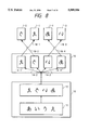
- FIG. 4 is an explanatory view of the image display element for displaying image information with a large field of view in this embodiment.
- FIG. 4 shows processing steps of dividing a large single image 11 into three images, and divisionally displaying the three images on the three LCDs 1-1, 1-2, and 1-3 (the number of divided images is not limited to 3).
- the image 11 is generated by a computer 10, and is converted into a mirror image 12. Thereafter, the mirror image 12 is supplied to an image dividing circuit 15.
- the image dividing circuit 15 divides the mirror image 12 into partial images 14 (14-1, 14-2, and 14-3) to be displayed on the LCDs (1-1, 1-2, and 1-3).
- the circuit 15 supplies the partial image 14-1 to the LCD 1-1 via a signal line 16-1, the partial image 14-2 to the LCD 1-2 via a signal line 16-2, and the partial image 14-3 to the LCD 1-3 via a signal line 16-3.
- the LCD 1 is illustrated as a plan view when the LCD 1 is viewed from the reflection type HOE 2 in FIG. 3.
- LCD frames 1-1-b, 1-2-b, and 1-3-b protect and fix the LCDs 1-1, 1-2, and 1-3, respectively, and are assembled with electronic circuits. Image information is displayed on regions 1-1-a, 1-2-a, and 1-3-a of the LCDs 1.
- the gap between the LCDs 1-1 and 1-2 is represented by L1
- the gap between the LCDs 1-2 and 1-3 is represented by L2.
- FIG. 5 is an explanatory view of an optical system for explaining the function of the reflection type HOE 2 of this embodiment.
- the reflection type HOE 2 is constituted by connecting the volume phase reflection type elementary HOEs 2-1, 2-2, and 2-3 without gaps.
- the elementary HOE 2-1 reflects light radiated from all points on the LCD 1-1, and projects the reflected light onto the pupil 7 of the left eye. Furthermore, the elementary HOE 2-1 has an optical power, and projects all the points on the LCD 1-1 on a portion 26 on a virtual image plane 21 as a virtual image.
- a light beam 17 radiated from a point 34 on the LCD 1-1 is reflected by the elementary HOE 2-1, and is incident as a reflected light beam 26 on the pupil 7 of the left eye.
- the imaginary light beam 30 obtained by extending the reflected light beam 26 in a direction opposite to the light propagation direction, the imaginary light beam 30 converges at a point 25 on the virtual image plane 21. More specifically, the observer recognizes the reflected light beam 26 as if the light beam were radiated from the point 25 on the virtual image plane 21.
- the elementary HOE 2-2 projects points on the LCD 1-2 on the pupil 7 of the left eye as points on a corresponding portion 27 on the virtual image plane 21, and the elementary HOE 2-3 projects points on the LCD 1-3 on the pupil 7 of the left eye as points on a corresponding portion 28 on the virtual image plane 21.
- a point 35-1 on the LCD 1-1 and a point 35-2 on the LCD 1-2 are an identical point on image data, as shown in FIG. 4.
- a light beam 18-1 radiated from the point 35-1 and incident on the elementary HOE 2-1 is reflected by the elementary HOE 2-1, and is incident on the pupil 7 of the left eye as a reflected light beam 27-1.
- a light beam 18-2 radiated from the point 35-2 and incident on the elementary HOE 2-2 is reflected by the elementary HOE 2-2, and is incident on the pupil 7 of the left eye as a reflected light beam 27-2.
- the elementary HOEs 2-1 and 2-2 are set, so that imaginary light beams 31-1 and 31-2 obtained by extending the reflected light beams 27-1 and 27-2 in directions opposite to their propagating directions converge at an identical point 24 on the virtual image plane 21.
- the elementary HOEs 2-1, 2-2, and 2-3 are set for all the points on the LCDs 1-1, 1-2, and 1-3 corresponding to positions on the joints of partial images in the same manner as the points 35-1 and 35-2.
- the HOE 2 may be manufactured by adhering elementary HOEs (2-1, 2-2, and 2-3) independently obtained by a known 2-beam interference exposure method, or the elementary HOEs 2-1, 2-2, and 2-3 may be manufactured by masking an unnecessary portion of a single hologram substrate, and sequentially performing exposure three times on the hologram substrate (triple exposure method).
- the HOE is recorded by the triple exposure method using a photopolymer.
- an observer recognizes three pieces of image information displayed on the LCDs 1-1, 1-2, and 1-3 as an image projected on the flat virtual image plane 21 by the reflection type elementary HOEs 2-1, 2-2, and 2-3.
- the virtual image plane 21 is not limited to a flat plane.
- the virtual image plane 21 may be a cylindrical plane, which surrounds an observer.
- the power distribution of the reflection type elementary HOEs 2-1, 2-2, and 2-3 can be set to define the virtual image plane not as a flat plane but as a cylindrical plane.
- a relief hologram on a surface of which a proper semi-transparent reflection film (e.g., a metal film) is deposited may be used.
- the three LCDs 1-1, 1-2, and 1-3 are arranged on a single plane.
- these LCDs need not always be arranged on a single plane but may be arranged on different planes.
- four or more LCDs may be arranged.
- identical image information may be displayed on the right and left eyes, or different image information having a parallax may be displayed for the right and left eyes, so that the observer can recognize a 3-dimensional image.
- image information may be set, so that one eye recognizes a background image, and the other eye recognizes a foreground image.
- image information generated by the computer is used as image information.
- image information obtained by divisionally displaying an image from a TV camera or a VTR on the three LCDs 1-1, 1-2, and 1-3 by a computer or another method may be used.
- an image obtained by divisionally displaying image information picked up using three TV cameras of the current NTSC level on the LCDs 1-1, 1-2, and 1-3, may be used.
- FIG. 6 is an explanatory view showing processing steps of displaying image information picked up by three cameras.
- Three TV cameras 61-1, 61-2, and 61-3 pick up partial images obtained by dividing a landscape 60 into three images as image information. At this time, the vertical and horizontal directions of the three TV cameras are reversed with respect to a case wherein image information is normally picked up.
- a mount for fixing the TV cameras horizontally may be used, or incident images may be converted into horizontal images by attaching prism attachments in front of photographing lenses of the TV cameras.
- distances L3 and L4 between the two adjacent TV cameras must be adjusted.
- the TV cameras are fixed by a mount with stages.
- the landscape 60 is picked up as three pieces of image information 14-1-a, 14-2-a, and 14-3-a by the TV cameras 61-1, 61-2, and 61-3, and these pieces of image information are respectively converted into mirror images 14-1-b, 14-2-b, and 14-3-b by mirror image circuits 62-1, 62-2, and 62-3. These mirror images are then supplied to and displayed on the LCDs 1-1, 1-2, and 1-3.
- the three pieces of image information displayed on the LCDs 1-1, 1-2, and 1-3 are projected onto the pupil of the observer, so that they are connected as single image information by the reflection type HOE, and are observed as an image similar to the landscape 60.
- high-definition image information can be displayed on a large screen having a remarkably large number of pixels using existing LCDs.
- FIG. 7 is a schematic partial plan view showing the second embodiment of the present invention.
- FIG. 7 illustrates elements for only the left eye of an observer as in the first embodiment shown in FIG. 3, and the same reference numerals in FIG. 7 denote the same parts as in FIG. 3.
- LCDs (1-1, 1-2, 1-3, and 1-4) are used as image display elements.
- elementary hologram optical elements (elementary HOEs) 2-1, 2-2, 2-3, and 2-4 are used as a hologram optical element 2, and are connected to each other without any gaps.
- some light components of a light beam from a point 35-1 on the LCD 1-1 are incident on an elementary HOE other than the corresponding elementary HOE 2-1, e.g., on the elementary HOE 2-2.
- the amount of light from the point 35-1 and reflected by the elementary HOE 2-2 is small due to the angular selectivity, as a volume phase type hologram, of the elementary HOE 2-2, it is difficult to perfectly cut reflected light since the point 35-1 is spatially close to a point 35-2.
- some light components of a light beam from the point 35-1 are reflected by the elementary HOE 2-2, and the reflected light may become incident on the left eye as a ghost.
- the embodiment shown in FIG. 7 can prevent generation of such a ghost.
- the four LCDs and the corresponding four elementary HOEs are arranged to have different incident angles.
- the incident angle of a light beam from an LCD (1-1, 1-2, 1-3, or 1-4) corresponding to a given elementary HOE (2-1, 2-2, 2-3, or 2-4) is largely different from the incident angles of light beams from other LCDs to the given elementary HOE, thereby eliminating generation of a ghost.
- the LCDs (1-1, 1-2, 1-3, and 1-4) display different image information, and are illuminated with a light beam from a backlight light source 4 via a diffraction grating 5.
- the diffraction grating 5 improves illumination efficiency.
- Light beams 8-1, 8-2, 8-3, and 8-4 having the image information on the LCDs 1 are incident on the corresponding elementary HOEs 2-1 to 2-4.
- the light beam 8-1 from the LCD 1-1, the light beam 8-2 from the LCD 1-2, the light beam 8-3 from the LCD 1-3, and the light beam 8-4 from the LCD 1-4 are incident on the corresponding elementary HOEs 2-1, 2-2, 2-3, and 2-4 to cross each other.
- the elementary HOEs 2-1, 2-2, 2-3, and 2-4 respectively reflect the light beams 8-1, 8-2, 8-3, and 8-4 including the image information, and project them onto a pupil 7 of the left eye as reflected light beams 9-1, 9-2, 9-3, and 9-4.
- An observer connects image information displayed on the LCDs 1-1, 1-2, 1-3, and 1-4 without any gaps on the basis of the four light beams 9-1, 9-2, 9-3, and 9-4 incident on his or her left eye without any gaps on the basis of the image information on the LCDs 1-1, 1-2, 1-3, and 1-4, and visually observes them as single large image information.
- FIG. 8 is an explanatory view showing processing steps of dividing single large image information into four pieces of information, and divisionally displaying the four pieces of information on the four LCDs 1-1, 1-2, 1-3, and 1-4 in this embodiment.
- An image 11 is generated by a computer 10, and is converted into a mirror image 12. Thereafter, the mirror image 12 is supplied to an image dividing circuit 15.
- the image dividing circuit 15 divides the mirror image 12 into partial images 14-1, 14-2, 14-3, and 14-4 to be displayed on the four LCDs 1-1, 1-2, 1-3, and 1-4.
- the partial images 14-1, 14-2, 14-3, and 14-4 are supplied to and displayed on the LCDs 1-1, 1-2, 1-3, and 1-4 via signal lines 16-1, 16-2, 16-3, and 16-4.
- the HOE 2 is constituted by connecting the elementary HOEs 2-1, 2-2, 2-3, and 2-4 as four different volume phase reflection type holograms without any gaps.
- the elementary HOE 2-1 is set to substantially cause Bragg diffraction with respect to the light beam 8-1 having image information from the LCD 1-1, thereby generating the reflected light beam 9-1.
- the elementary HOE 2-2 is set to substantially cause Bragg diffraction with respect to the light beam 8-2 having image information from the LCD 1-2, thereby generating the reflected light beam 9-2.
- the elementary HOE 2-3 is set to substantially cause Bragg diffraction with respect to the light beam 8-3 having image information from the LCD 1-3, thereby generating the reflected light beam 9-3.
- the elementary HOE 2-4 is set to substantially cause Bragg diffraction with respect to the light beam 8-4 having image information from the LCD 1-4, thereby generating the reflected light beam 9-4.
- the HOE 2 projects points on the LCDs 1-1, 1-2, 1-3, and 1-4 on a virtual image plane (not shown) in FIG. 7 as a virtual image, and allows an observer to observe an enlarged image similar to the image information shown in FIG. 8 on the virtual image plane, like in the reflection type HOE 2 in the first embodiment.
- the light beams 8-1 and 8-2 from the LCDs 1-1 and 1-2 are incident on the corresponding elementary HOEs 2-1 and 2-2 to cross each other.
- the light beams 8-3 and 8-4 from the LCDs 1-3 and 1-4 are incident on the corresponding elementary HOEs 2-3 and 2-4 to cross each other.
- the elementary HOEs 2-1, 2-2, 2-3, and 2-4 are set to substantially cause Bragg diffraction to the light beams 8-1, 8-2, 8-3, and 8-4, respectively. For this reason, stray light from LCDs other than the corresponding LCD and incident on non-corresponding elementary HOEs is not diffracted by the elementary HOEs due to the angular selectivity of the HOEs, and is transmitted therethrough. As a result, such stray light can be prevented from being incident on the pupil 7 of the left eye.
- This embodiment can effectively eliminate generation of a ghost in this manner.
- FIG. 9 is an explanatory view showing the optical function of the diffraction grating 5 of this embodiment.
- the diffraction grating 5 is constituted by connecting four blade transmission type elementary diffraction gratings 5-1, 5-2, 5-3, and 5-4.
- the elementary diffraction gratings 5-1, 5-2, 5-3, and 5-4 deflect a light beam from the backlight light source 4 to efficiently illuminate the LCDs 1-1, 1-2, 1-3, and 1-4, thereby generating the light beams 8-1, 8-2, 8-3, and 8-4.
- a volume phase type hologram may be used in place of the diffraction grating 5 in this embodiment.
- a Fresnel lens may be used.
- FIG. 10 is a schematic partial plan view showing the third embodiment of the present invention.
- FIG. 10 illustrates elements for only the left eye of an observer as in the first embodiment shown in FIG. 3, and the same reference numerals in FIG. 10 denote the same parts as in FIG. 3.
- a light beam from an image display element (LCD) 1 is reflection-diffracted twice using two reflection type hologram optical elements (HOEs 2a and 2b) so as to eliminate a chromatic aberration generated by the holograms, thus allowing observation of satisfactory image information.
- HOEs 2a and 2b reflection type hologram optical elements
- a reflection type HOE 2a is constituted by connecting two different elementary HOEs 2a-1 and 2a-2.
- a reflection type HOE 2b is constituted by connecting two different elementary HOEs 2b-1 and 2b-2 without any gaps (in the HOE 2a, the two elementary HOEs 2a-1 and 2a-2 may be arranged to be separated from each other within an allowable range or may be arranged on different planes).
- the LCDs 1-1 and 1-2 display different image information, and are effectively illuminated with a light beam from a backlight light source 4 via a diffraction grating 5.
- a light beam 8-1 (8-2) from the LCD 1-1 (1-2) is incident on the elementary HOE 2a-1 (2a-2).
- the elementary HOE 2a-1 reflects the incident light beam 8-1, and radiates it on the elementary HOE 2b-1 as a reflected light beam 9-1-a.
- the elementary HOE 2a-1 reflects the incident light beam 8-2, and radiates it onto the elementary HOE 2b-2 as a reflected light beam 9-2-a.
- the elementary HOE 2b-1 reflects the light beam 9-1-a, and guides it to a pupil 7 of the left eye as a reflected light beam 9-1-b.
- the elementary HOE 2b-2 reflects the light beam 9-2-a, and guides it to the pupil 7 of the left eye as a reflected light beam 9-2-b.
- the light beams 9-1-b and 9-2-b respectively have image information displayed on the LCDs 1-1 and 1-2. An observer can recognize image information displayed on the LCDs 1-1 and 1-2, and connected to each other without any gaps.
- FIG. 11 is an explanatory view of processing steps for dividing single large image information into two pieces of information, and divisionally displaying the two pieces of image information on the two LCDs 1-1 and 1-2.
- a computer 10 generates an image 11, and supplies it to an image dividing circuit 15.
- the image dividing circuit 15 divides the image 11 into two partial images 14-1 and 14-2 so as to display it on the LCDs 1-1 and 1-2.
- the partial image 14-1 is supplied to the LCD 1-1 via a signal line 16-1
- the partial image 14-2 is supplied to the LCD 1-2 via a signal line 16-2.
- the LCDs 1-1 and 1-2 respectively display the partial images 14-1 and 14-2.
- the elementary HOE 2a-1 is set to substantially cause Bragg diffraction of the light beam 8-1 from the LCD 1-1.
- the elementary HOE 2a-2 is set to substantially cause Bragg diffraction of the light beam 8-2 from the LCD 1-2.
- the LCDs 1-1 and 1-2, and the elementary HOEs 2a-1 and 2a-2 are arranged, so that the light beams 8-1 and 8-2 from the LCDs 1-1 and 1-2 are incident on the elementary HOEs 2a-1 and 2a-2 to cross each other. Stray light from the LCD 1-1 is incident on the elementary HOE 2a-2 at an angle considerably different from that of the regular light beam 8-2 incident from the LCD 1-2 onto the elementary HOE 2a-2.
- stray light from the LCD 1-2 is incident on the elementary HOE 2a-1 at an angle considerably different from that of the regular light beam 8-1 incident from the LCD 1-1 onto the elementary HOE 2a-1. For this reason, stray light incident from the LCD 1-2 onto the elementary HOE 2a-1 and stray light incident from the LCD 1-1 onto the elementary HOE 2a-2 are not diffracted but are transmitted through the corresponding elementary HOEs 2a-1 and 2a-2, and do not become incident on the elementary HOEs 2b-1 and 2b-2. Therefore, such stray light does not finally reach the pupil 7 of the observer. In this embodiment, generation of a ghost is prevented like in the second embodiment.
- the light beam 8-1 (8-2) having image information from the LCD 1-1 (1-2) is diffracted twice by the elementary HOEs 2a-1 and 2b-1 (the elementary HOEs 2a-2 and 2b-2), thereby providing the following effects. That is, a chromatic aberration generated upon diffraction by the HOE can be eliminated, and a mirror image of an image to be displayed need not be formed.
- FIG. 12 is a schematic partial plan view showing the fourth embodiment of the present invention.
- the entire image information to be observed by an observer is not equally displayed with high definition, and only an image area frequently observed by the observer is displayed with particularly high definition.
- image information is divided into a plurality of (five) regions, and of these regions, three image information regions are displayed with higher definition than other regions.
- LCDs 1-1 to 1-5 have the same specifications, and are illuminated with a light beam from a backlight light source (not shown) via a diffraction grating (not shown) for improving illumination efficiency in the same manner as in the above-mentioned embodiments.
- the LCDs 1-1, 1-2, and 1-3 are arranged on a plane separated by a distance L1 from a reflection type HOE 2, and the LCDs 1-4 and 1-5 are arranged on a plane separated by a distance L4 from the reflection type HOE 2.
- the LCDs 1-1 to 1-5 display different image information.
- a light beam having image information displayed on the LCD 1-1 is incident on an elementary HOE 2-1, is reflected by the elementary HOE 2-1, and is then incident on a pupil 7 of an observer.
- a light beam from the LCD 1-2 (1-3, 1-4, 1-5) is reflected by an elementary HOE 2-2 (2-3, 2-4, 2-5), and is incident on the pupil 7 of the observer.
- the observer connects five pieces of image information displayed on the LCDs 1-1 to 1-5 via the HOE 2, and observes them as continuous single large image information.
- the reflection type HOE 2 comprises a volume phase reflection type hologram, and is constituted by connecting the five elementary HOEs 2-1, 2-2, 2-3, 2-4, and 2-5 without any gaps.
- FIG. 13 is a schematic plan view showing an optical system of this embodiment when viewed from a position above the head of the observer.
- backlight light sources 4-1 to 4-5 respectively illuminate the LCDs 1-1 to 1-5.
- Diffraction gratings 5-1 to 5-5 deflect light beams from the backlight light sources 4-1 to 4-5 to effectively illuminate the LCDs 1-1 to 1-5.
- FIG. 13 does not illustrate the backlight light source 4-5, the diffraction grating 5-5, and the elementary HOEs 2-1, 2-2, 2-3, and 2-5 since they are located behind the backlight light source 4-4, the diffraction grating 5-4, and the elementary HOE 2-4 and cannot be seen.
- the LCDs (1-1 to 1-5) display different image information, and are illuminated with light beams from the backlight light sources (4-1 to 4-5) opposing the LCDs (1-1 to 1-5) via the corresponding diffraction gratings (5-1 to 5-5).
- the light beams (8-1 to 8-5) including image information of the LCDs (1-1 to 1-5) are respectively incident on the elementary HOEs (2-1 to 2-5).
- the elementary HOEs (2-1 to 2-5) respectively reflect these light beams (8-1 to 8-5), and guide them to the pupil of the observer as reflected light beams (9-1 to 9-5).
- the observer recognizes image information displayed on the LCDs (1-1 to 1-5) as single large image information connected without any gaps on the basis of the five light beams (9-1 to 9-5) having image information of the LCDs (1-1 to 1-5) and incident on the pupil 7 of the left eye without any gaps.
- a virtual image plane 21 in FIG. 13 is separated by a predetermined distance L (e.g., 1 m) from the HOE 2.
- the elementary HOEs 2-1, 2-2, 2-3, 2-4, and 2-5 respectively cause the observer to recognize points on the LCDs 1-1, 1-2, 1-3, 1-4, and 1-5 as virtual image points on the virtual image plane 21 in the same manner as the elementary HOEs in the first embodiment described above.
- FIG. 14 is an explanatory view showing processing steps of non-equally dividing single large image information into five pieces of image information, enlarging/reducing the five pieces of image information at non-equal magnifications, and divisionally displaying them on the five LCDs.
- a computer 10 generates an image 11, and the image 11 is converted into a mirror image 12. Thereafter, the mirror image 12 is supplied to an image dividing circuit 15-a.
- the image dividing circuit 15-a non-equally divides the mirror image 12 into five partial images 14-1-a, 14-2-a, 14-3-a, 14-4-a, and 14-5-a to be displayed on the LCDs 1-1, 1-2, 1-3, 1-4, and 1-5.
- each of the partial images 14-4-a and 14-5-a is constituted by m max pixels
- each of the partial images 14-1-a, 14-2-a, and 14-3-a is constituted by m min pixels.
- m max and m min are respectively defined by: ##EQU1##
- the value M obtained by converting the number of data constituting the original image 11 into the number of pixels is determined to satisfy m min ⁇ m LCD and m min ⁇ m LCD (where m LCD is the number of pixels of the LCD 1 used in this embodiment).
- the five partial images 14-1-a, 14-2-a, 14-3-a, 14-4-a, and 14-5-a divided by the image dividing circuit 15-a are supplied to a sampling circuit 15-b.
- the sampling circuit 15-b converts the partial images 14-1-a, 14-2-a, and 14-3-a into image data 14-1-b, 14-2-b, and 14-3-b having the same number of data as the number m LCD of pixels of the LCD, and supplies these image data to the LCDs 1-1, 1-2, and 1-3.
- the sampling circuit 15-b samples the partial images 14-4-a and 14-5-a to convert them into image data 14-4-b and 14-5-b having the same number of data as the number m LCD of pixels of the LCD, and supplies them to the LCDs 1-4 and 1-5. Since the distance L1 between the LCDs 1-1, 1-2, and 1-3, and the HOE 2 is larger than the distance L4 between the LCDs 1-4 and 1-5, and the HOE 2, m min and m max satisfy m max >m min , and m min ⁇ m LCD , the partial images 14-4-b and 14-5-b are converted into coarse data having a smaller number of data than that of the partial image data 14-4-a and 14-5-a before sampling.
- Images displayed on the LCDs 1-4 and 1-5 are reduced at a ratio of L4/L1 with respect to images displayed on the LCDs 1-1, 1-2, and 1-3.
- the observer recognizes image information on the LCDs 1-1, 1-2, and 1-3 as a virtual image in an enlarged scale of L/L1 on the virtual image plane, and recognizes images on the LCDs 1-4 and 1-5 as a virtual image in an enlarged scale of L/L4 on the virtual image plane.
- Images displayed on the LCDs 1-4 and 1-5 are displayed in a reduced scale of L4/L1 with respect to images displayed on the LCDs 1-1 to 1-3, and are displayed for the observer on the virtual image plane in an enlarged scale of L/L4.
- the observer recognizes that a portion to be observed by the observer based on images displayed on the LCDs 1-1, 1-2, and 1-3, and a portion to be observed by the observer based on images displayed on the LCDs 1-4 and 1-5 have different areas. However, since each of these partial images has the same number of pixels, an image portion observed based on the images displayed on the LCDs 1-1, 1-2, and 1-3 is observed by the observer as an image having higher definition than an image portion observed based on images displayed on the LCDs 1-4 and 1-5.
- FIG. 15 is a schematic partial plan view showing the fifth embodiment of the present invention.
- LCDs 1-1 and 1-2 display different image information.
- the LCDs 1-1 and 1-2 are illuminated with light beams emitted from corresponding backlight light sources 4-1 and 4-2 and focused by corresponding condenser lenses 35-1 and 35-2.
- the LCDs 1-1 and 1-2 output light beams 8-1-a and 8-2-a having image information displayed thereon.
- Imaging lenses 34-1 and 34-2 form images of the LCDs 1-1 and 1-2 as intermediate images 36-1 and 36-2, and convert the light beams 8-1-a and 8-2-a into light beams 8-1-b and 8-2-b, respectively.
- a reflection type HOE 2 is constituted by connecting elementary HOEs 2-1 and 2-2 without any gaps as in the reflection type HOE in the first embodiment described previously.
- the HOE 2 reflects the light beams 8-1-b and 8-2-b, and radiates them onto a pupil 7 of an observer as reflected light beams 9-1 and 9-2.
- an observer recognizes image information displayed on the LCDs 1-1 and 1-2 as single large image information projected onto a virtual image plane 21 and connected without any gaps.
- magnification between the LCD 1-1 and the intermediate image 36-1 is represented by m 1-a
- magnification between the LCD 1-2 and the intermediate image 36-2 is represented by m 2-a
- magnification between the intermediate image 36-1 and a virtual image on the virtual image plane 21 is represented by m 1-b
- magnification between the intermediate image 36-2 and a virtual image on the virtual image plane 21 is represented by m 2-b
- FIG. 16 is an explanatory view showing processing steps of dividing single large image into two pieces of image information, and divisionally displaying the two pieces of image information.
- a computer 10 generates an image 11, and the image 11 is converted into a mirror image 12.
- the mirror image 12 is supplied to a dividing circuit 15-a.
- the dividing circuit 15-a divides the mirror image 12 into two partial images 14-1-a and 14-2-a, and supplies these partial images to an inverting circuit 15-c.
- the inverting circuit 15-c inverts the partial images 14-1-a and 14-2-a into inverted partial images 14-1-c and 14-2-c, and supplies these inverted partial images to the LCDs 1-1 and 1-2.
- m 1-a ⁇ m 1-b and m 2-a ⁇ m 2-b may be set to have different values.
- an image on either LCD can be displayed in an enlarged scale as in the fourth embodiment of the present invention.
- FIG. 17 is a schematic view showing the main part of the sixth embodiment of the present invention.
- rays indicated by solid lines and alternate long and short dashed lines represent light beams from the central portion of an image display element
- rays indicated by broken lines and alternate long and two short dashed lines represent imaginary rays.
- Light beams emitted from backlight light sources 71 and 72 comprising, e.g., halogen lamps, fluorescent lamps, or the like are modulated by image display elements 73 and 74 such as LCD elements to be converted into image display light beams 75 and 76.
- the light beams 75 and 76 are incident on a holographic optical element (to be abbreviated as an "HOE" hereinafter) 78 formed on a glass or plastic substrate 77.
- the HOE 78 has double-exposed two-lens effects, converts the light beams 75 and 76 respectively emitted from points 79 and 80 into wavefronts as if they diverge from points 79a and 80a, and radiates the converted wavefronts onto a pupil 81 of an observer.
- the HOE 78 similarly wavefront-converts light beams from other points on the image display elements. Thus, an observer recognizes image information on the image display elements 73 and 74 as a virtual image 82.
- FIG. 17 illustrates only light beams from the central points 79 and 80 on the image display elements 73 and 74.
- FIG. 18 is a schematic optical path chart of light beams having field angles.
- points 87, 79, and 88, and points 89, 80, and 90 on the image display elements 73 and 74 correspond to points 87a, 79a, and 88a, and points 89a, 80a, and 90a on a virtual image plane 82.
- Image information to be displayed in this embodiment will be described below with reference to FIG. 19.
- an input image signal 86 is an arrow inclined through 45°.
- the input image signal 86 is input to drivers 83 and 84 under the control of a controller 85, and identical arrow images displayed (in FIG. 19, pixels are expressed by ⁇ and ⁇ marks for the sake of simplicity).
- the central points 79 and 80 on the image display elements 73 and 74 are displayed as the points 79a and 80a to be two-dimensionally shifted by half a pixel pitch on the virtual image plane 82.
- high-definition image information is displayed by interpolating information between two adjacent pixels.
- the HOE 78 used in this embodiment As a method of manufacturing the HOE 78 used in this embodiment, a known technique can be utilized. In this embodiment, a volume phase hologram recorded on a photopolymer by a 2-beam interference method using an argon-ion laser is used.
- a monochrome laser beam having a wavelength of 514.5 nm emitted from an argon-ion laser is split into two beams.
- the two beams are guided to become incident on the front and rear surfaces of a hologram photosensitive material 78, so that one beam is defined as a divergent beam from a point 79c corresponding to the point 79 in FIG. 17, and the other beam is defined as a divergent beam from a point 79d corresponding to the point 79a, or one beam is defined as a divergent beam from a point 80c corresponding to the point 80, and the other beam is defined as a divergent beam from a point 80d corresponding to the point 80a.
- the photosensitive material is exposed with the laser beam in an arrangement shown in FIG. 20, and is then exposed with the laser beam in an arrangement shown in FIG. 21. Thereafter, the hologram optical element HOE shown in FIG. 17 can be obtained by developing the hologram photosensitive material.
- the refractive index of the hologram photosensitive material almost coincides with that of the glass substrate 77.
- a so-called Lippmann hologram is recorded.
- a light beam 70A is substantially the same as a light beam 70B, except that they have slightly different incident angles onto the hologram photosensitive material.
- the light beam 70A i.e., a divergent light beam from the point 79d may be used in place of the light beam 70B in FIG. 21.
- FIGS. 22 and 23 are explanatory views showing another hologram recording optical system.
- the points 79c and 80c are the same as those in FIGS. 20 and 21, a point 79e is symmetrical with the point 79d with respect to a hologram surface, and a point 80e is symmetrical with the point 80d with respect to the hologram surface.
- Interference fringes from divergent light beams from the two points 79c and 79e in FIG. 22 are recorded, and then, interference fringes from divergent light beams from the two points 80c and 80e in FIG. 23 are recorded.
- the hologram photosensitive material is developed, and thereafter, a half mirror film 70c is coated on the glass substrate 77, as shown in FIG. 24.
- the hologram (FIG. 24) prepared in this manner is set at a position of the HOE 78 (FIG. 17), a hologram optical element having the same effect can be obtained.
- a light beam from the point 79e can be used in place of a light beam from the point 80e in FIG. 23.
- This HOE 78 is suitable for mass-production since the interference fringes to be recorded have a low spatial frequency unlike the above-mentioned Lippmann hologram. Furthermore, interference fringes are recorded using a photoresist as a photosensitive material, and the photoresist is developed to obtain a relief type hologram. A replica is formed using the obtained relief type hologram as a master hologram, and a structure obtained by coating a half mirror film on the relief structure of the replica hologram can be used at the position of the HOE 78 in FIG. 17. In this manner, a hologram combiner can be manufactured with lower cost. In the above-mentioned examples of the manufacturing method, multiple exposure is performed. Alternatively, exposure operations shown in FIGS. 20 and 21 may be performed at different positions on a single photosensitive member to manufacture a hologram. In this case, image display light beams need only be incident at different positions on a hologram.
- FIG. 25 is a schematic view showing the main part of the seventh embodiment of the present invention. This embodiment is substantially the same as the sixth embodiment, except that a transmission type HOE is used, intermediate images are formed, and an eyepiece is used.
- light beams 75 and 76 emerging from points 79 and 80 on image display elements 73 and 74 are imaged by a transmission type HOE 78 as points 79a and 80a on an intermediate imaging plane 91, and two images are synthesized, so that their pixels interpolate each other, as has been described above with reference to FIG. 19.
- a synthesized image synthesized by the HOE is a virtual image, while in this embodiment, a spatial image of a real image is synthesized on the intermediate imaging plane 91.
- the synthesized spatial image is incident on a pupil 81 of an observer using an eyepiece lens 92, and the observer can recognize a high-definition synthesized image.
- a screen may be arranged at the position of the intermediate imaging plane 91, images are synthesized on the screen, and the synthesized image may be observed using the eyepiece lens 92.
- the NA of the eyepiece lens 92 can be decreased, thus achieving a compact apparatus.
- FIG. 26 is a schematic view showing the main part of the eighth embodiment of the present invention.
- three image display elements are arranged, and three pieces of image information are synthesized to display high-definition image information.
- image information is synthesized by two HOEs, i.e., a reflection type HOE 133 adhered between prisms 135 and 136, and a reflection type HOE 134 adhered between the prisms 137 and 138.
- the most simple HOE element can be an element, which is recorded to diffract an incident plane wave at an angle slightly different from the incident angle, and has no lens function.
- the HOEs 133 and 134 are set so that a point 100A is projected on a point 100Aa via the two HOEs 133 and 134, a point 100B is projected by the reflection type HOE 133 onto a point 100Ba diffracted at an angle slightly shifted from a positive reflection angle, and a point 100C is projected onto a point 100Ca by the HOE 134.
- the points 100Aa, 100Ba, and 100Ca are set at positions to interpolate information between corresponding pixels.
- an observer can recognize high-definition synthesized image information in which information between pixels is interpolated by the three images.
- a means for adjusting the brightness levels of backlight light sources 131-a, 131-b, and 131-c in consideration of the diffraction efficiency of the HOEs 133 and 134 may be arranged.
- the diffraction efficiency of the HOE 133 is set to be 50%, and the diffraction efficiency of the HOE 134 is set to be 33.33%, three pieces of image information can have substantially equal luminance levels.
- FIGS. 27A and 27B are schematic views showing the main part of the ninth embodiment of the present invention.
- the present invention is applied to an output apparatus for a wordprocessor.
- FIG. 27A is a perspective view of the overall apparatus
- FIG. 27B is a side view of the apparatus.
- the arrangement and function of this embodiment are basically the same as those of the sixth embodiment.
- an apparatus portion including control circuits such as the controller 85, the drivers 83 and 84, and the like in the sixth embodiment is stored together in a main body portion 141.
- An output signal from a wordprocessor 142 is input to the apparatus main body 141 via a signal line 143.
- a pivotal/expandable arm 144 is attached to the side surface of the apparatus main body 141, and can be adjusted in accordance with the body dimensions or desired position of an observer.
- Driver signals to image display elements 103 and 104, power cables for backlight light sources 101 and 102, and the like are arranged in this arm 144.
- the lens effect of an HOE 108 is set, so that a virtual image 112 synthesized by the HOE is formed near a keyboard as an observation point of the observer.
- the observer can simultaneously observe an input result, a displayed figure, and the like while watching keys on the keyboard without turning away his or her eyes from the keyboard.
- the observation point, the virtual image, and the keyboard coincide with each other, a fatigue caused by focus adjustment of pupils can be reduced.
- the present invention is applied to the wordprocessor.
- the present invention can also be applied to an output apparatus for a CAD system, which requires a high-definition image display.
- the HOE can be set, so that a synthesized virtual image 112 is formed on an input device such as a digitizer.
- FIGS. 28A and 28B are schematic views showing the main part of the 10th embodiment of the present invention.
- the present invention is applied to a so-called holographic display.
- a 3-dimensional image can be observed by providing two pieces of image information having a parallax therebetween to two systems for the right and left eyes.
- An optical arrangement and its function for each eye are the same as those in the sixth embodiment, and a detailed description thereof will be omitted.
- a vergence angle ⁇ is provided between the optical axes of the optical systems for the right and left eyes, so that corresponding origins of two images cross at a point 100F at a virtual image position 112.
- a conventional head-mount display (to be referred to as an HMD hereinafter) causes fatigues of the eyes and physiological discomfort owing to parallel visual axis directions although a generated virtual image position is not an infinity position.
- this embodiment can solve such problems.
- image signals of images for the right and left eyes which images are formed by a 3-dimensional image control circuit 155, and have a parallax therebetween, are added with control signals such as proper synchronization signals, and the like, and are respectively input to image control circuits 153 and 154 for the right and left eyes.
- a plurality of image display elements for each eye (not shown in FIG. 28B; elements 103 and 104 for the left eye in FIG. 28A) are driven to display a predetermined image.
- Predetermined images on the plurality of image display elements are synthesized by HOEs 107 and 107a on the virtual image plane 112, so that pixels of these images interpolate each other, thus presenting high-definition images to corresponding pupils (eyes) 111 and 11a of the observer.
- the observer can recognize a high-definition image having a binocular parallax as a 3-dimensional view factor.
- the system displays images to have a vergence angle ⁇ therebetween.
- an apparatus for displaying a high-definition image as the characteristic feature of the present invention is not limited to this system.
- the two optical systems are arranged parallel to each other like in the conventional HMD, the same effect as in this embodiment can be provided.
- the signal cable 152 is used.
- power sources for the backlight light sources of the image display elements may be used as batteries, and signals may be transmitted using infrared rays in a wireless manner.
- an image display apparatus which can display high-definition image information on a large screen, can be provided.
- an image display apparatus which can effectively synthesize image information based on the plurality of image display elements, and can display high-definition image information on a large screen, can be provided.
Abstract
An image display apparatus includes a plurality of image display elements respectively assigned to different partial image information regions of an image to be displayed, and a hologram optical element for diffracting a plurality of light beams from the plurality of image display elements and displaying the diffracted light beams as continuous single image information. By including a plurality of image display elements, each of the image display elements having a large number of pixels, and a hologram optical element for forming a synthesized image by diffracting a plurality of image light beams from the image display elements, the hologram optical element diffracts the plurality of image light beams so as to display a synthesized image by interpolating information between pixels of a plurality of images to be synthesized.
Description
This application is a continuation of application Ser. No. 08/102,995, filed Jul. 28, 1993, now abandoned.
1. Field of the Invention
The present invention relates to an image display apparatus and, more particularly, to an image display apparatus which can display image information displayed on an image display element with a large field of view with high definition by utilizing a hologram optical element while making the entire apparatus compact.
2. Related Background Art
Conventionally, as an image display apparatus which allows a user to observe realistic image with a large field of view information displayed on an image display element such as a liquid crystal element as an image on a large screen, a large-scale CRT display apparatus, a projection TV apparatus, and the like are used.
These image display apparatuses suffer from the following problems. That is, such an image display apparatus requires a large space, and the surrounding area must be kept dark to satisfactorily observe image information.
In order to solve these problems, for example, as shown in FIG. 1, there is proposed an image display apparatus wherein a light beam from an image display apparatus is directly guided to eyes (the pupils of an observer) using an optical system arranged near the face of the observer.
Referring to FIG. 1, a liquid crystal display (liquid crystal panel) 201 displays image information on the basis of image data sent via a signal line 206. A backlight light source 204 illuminates the liquid crystal display 201. A light beam 208 based on image information displayed on the liquid crystal display 201 is reflected by a mirror 205 via an enlarging lens unit 203 consisting of concave and convex lenses, and is incident on the eyes (observation pupils) of an observer 210 as a reflected light beam 209.
At this time, the enlarging lens unit 203 displays, as a virtual image, image information displayed on the liquid crystal display 201 on a virtual image plane 202 a predetermined distance (e.g., 5 m) ahead of pupils 207 of the observer via the mirror 205. Thus, the observer recognizes, on the virtual image plane, image information displayed on the liquid crystal display 201. The term "observe" is hereinafter defined as "observe with recognition".
There is also proposed an image display apparatus, which allows an observer to personally observe image information such as a television image in an enlarged scale using an optical device 225 attached to his or her head, as shown in FIG. 2. Note that FIG. 2 is a perspective view of main part of the apparatus when viewed from the obliquely lower direction.
The main part of the image display apparatus shown in FIG. 2 will be described below. The apparatus includes liquid crystal color televisions 221R and 221L for the right and left eyes. Some light components of image information displayed on each of the liquid crystal color televisions 221R and 221L are reflected by a trapezoidal beam splitter 222R (and 222L, not shown) arranged in front of each eye, and are incident on a front concave mirror 223. The light beam reflected by the concave mirror 223 is transmitted through the beam splitter 222R (222L), and is incident on the corresponding eye of an observer (not shown). Thus, the observer recognizes image information displayed on the liquid crystal color televisions 221R and 221L as a virtual image at a predetermined position in front of the concave mirror 223.
At this time, in order to compensate for shortage of the number of pixels of the liquid crystal display panels and not to show a joint between pixels, pixel positions of the liquid crystal color televisions 221R and 221L are determined, so that their pixels are shifted from each other, and pixels are sampling-displayed to be further shifted from the pixel positions.
The image display apparatus shown in FIG. 1 has a small image display element, and the number of pixels thereof is limited. For this reason, when an image is to be displayed with a large field of view in an enlarged scale, an observer undesirably recognizes pixels, and it is difficult for the observer to observe high-quality image information.
For example, when a compact liquid crystal display is used as an image display element, most of existing liquid crystal displays have about 300,000 pixels. For this reason, the liquid crystal display has a resolution as low as that of an NTSC signal output from a video tape recorder, and it is very difficult to display such image information with a large field of view or with high definition.
In the image display apparatus shown in FIG. 2, two pieces of image information shifted from each other by about 0.5 pitches are respectively observed by the right and left eyes.
But, in general, when two pieces of image information are respectively input to the right and left eyes of a man, he or she searches and determines the corresponding origins of the two pieces of image information from his or her eyes, and thereafter, performs edge detection of each image information, differential processing for detecting a binocular parallax, and the like, thus recognizing the image information.
In view of such an image recognition mechanism of humans, it is very difficult to interpolate information between pixels by observing two pieces of pixel-shifted image information by the two eyes, and to recognize a single high-definition image.
In most of the methods of observing two pieces of pixel-shifted image information by right and left eyes, the corresponding origins of the two pieces of image information are merely determined to be shifted from each other, and it is difficult to recognize such image information as different pixel-shifted image information.
The present invention has been made in consideration of the above-mentioned problems, and has as its object to provide an image display apparatus capable of displaying a high-definition image.
An image display apparatus according to the present invention displays light beams from a plurality of image display elements as continuous single image information via a hologram optical element.
An image display apparatus according to the present invention comprises a plurality of image display elements respectively assigned to image information of different partial regions of a display image, and a hologram element for diffracting a plurality of light beams from the plurality of image display elements, and displaying the diffracted light beams as continuous single image information.
An image display apparatus according to the present invention comprises a plurality of image display elements each having a large number of pixels, and a hologram optical element for diffracting a plurality of image light beams from the image display elements, and forming a synthesized image, and the hologram optical elements diffracts the plurality of image light beams so as to display a synthesized image obtained by interpolating information between pixels of a plurality of images to be synthesized.
FIG. 1 is a schematic sectional view showing the main part of a conventional image display apparatus;
FIG. 2 is a schematic perspective view showing the main part of another conventional image display apparatus;
FIG. 3 is a schematic partial plan view showing the first embodiment of the present invention;
FIG. 4 is an explanatory view of an image display element shown in FIG. 3;
FIG. 5 is a partial explanatory view of an optical path shown in FIG. 3;
FIG. 6 is a schematic partial plan view when the apparatus shown in FIG. 3 is partially modified;
FIG. 7 is a schematic partial plan view showing the second embodiment of the present invention;
FIG. 8 is an explanatory view of an image display element shown in FIG. 7;
FIG. 9 is an explanatory view of an optical effect of a diffraction grating shown in FIG. 7;
FIG. 10 is a schematic partial plan view showing the third embodiment of the present invention;
FIG. 11 is an explanatory view of an image display element shown in FIG. 10;
FIG. 12 is a schematic partial plan view showing the fourth embodiment of the present invention;
FIG. 13 is an explanatory view of an optical path in FIG. 12;
FIG. 14 is an explanatory view of an image display element shown in FIG. 12;
FIG. 15 is a schematic partial plan view showing the fifth embodiment of the present invention;
FIG. 16 is an explanatory view of an image display element shown in FIG. 15;
FIG. 17 is a schematic partial plan view showing the sixth embodiment of the present invention;
FIG. 18 is a partial explanatory view of an optical path shown in FIG. 17;
FIG. 19 is a partial explanatory view of FIG. 17;
FIG. 20 is an explanatory view of a method of manufacturing a hologram optical element shown in FIG. 17;
FIG. 21 is an explanatory view of the method of manufacturing the hologram optical element shown in FIG. 17;
FIG. 22 is an explanatory view of the method of manufacturing the hologram optical element shown in FIG. 17;
FIG. 23 is an explanatory view of the method of manufacturing the hologram optical element shown in FIG. 17;
FIG. 24 is an explanatory view of the hologram optical element shown in FIG. 17;
FIG. 25 is a schematic view showing the main part of the seventh embodiment of the present invention;
FIG. 26 is a schematic view showing the main part of the eighth embodiment of the present invention;
FIGS. 27A and 27B are respectively a schematic perspective view and a schematic side view of the ninth embodiment of the present invention; and
FIGS. 28A and 28B are respectively a schematic sectional view and a schematic plan view of the tenth embodiment of the present invention.
FIG. 3 is a partial schematic plan view showing the main part of an image display apparatus according to the first embodiment of the present invention.
FIG. 3 illustrates a state wherein only the left eye portion of an observer 6 is observed from a position above the head of the observer 6, and does not illustrate the right eye portion. However, the apparatus is symmetrical about the center of the face of the observer 6. Note that members for supporting respective elements are not shown in FIG. 3 for the sake of simplicity.
Referring to FIG. 3, liquid crystal displays (to be abbreviated as "LCDs" hereinafter) 1 (1-1, 1-2, and 1-3) as image display elements are arranged on a single plane. These LCDs receive different image signals sent via signal lines (not shown) connected thereto, and display different image information.
A backlight light source 4 illuminates the LCDs (1-1, 1-2, and 1-3), and light beams 8-1, 8-2, and 8-3 respectively emerge from the LCDs (1-1, 1-2, and 1-3).
A reflection type hologram optical element (to be abbreviated as an "HOE" hereinafter) 2 is constituted by connecting three different reflection type elementary hologram optical elements (to be referred to as "elementary HOEs" hereinafter) 2-1, 2-2, and 2-3 without any gap (although the reflection type elementary HOEs are used in this embodiment, basically the same arrangement can be used even when transmission type elementary HOEs are used). Of these elementary HOEs, the elementary HOE 2-1 reflects the light beam 8-1 based on image information displayed on the LCD 1-1, and guides the light beam to a pupil 7 of the left eye of the observer 6 as a reflected light beam 9-1.
Similarly, the elementary HOE 2-2 (2-3) reflects the light beam 8-2 (8-3) based on image information displayed on the LCD 1-2 (1-3), and guides the light beam to the pupil 7 of the left eye of the observer 6 as a reflected light beam 9-2 (9-3). At this time, the observer 6 recognizes three pieces of image information displayed on the three LCDs (1-1, 1-2, and 1-3) at a predetermined position in front of the HOE 2 as continuous single image information connected without gaps with a large field of view.
The respective elements of the image display apparatus of this embodiment will be described below.
FIG. 4 is an explanatory view of the image display element for displaying image information with a large field of view in this embodiment.
FIG. 4 shows processing steps of dividing a large single image 11 into three images, and divisionally displaying the three images on the three LCDs 1-1, 1-2, and 1-3 (the number of divided images is not limited to 3). The image 11 is generated by a computer 10, and is converted into a mirror image 12. Thereafter, the mirror image 12 is supplied to an image dividing circuit 15. The image dividing circuit 15 divides the mirror image 12 into partial images 14 (14-1, 14-2, and 14-3) to be displayed on the LCDs (1-1, 1-2, and 1-3). Of these partial images, the circuit 15 supplies the partial image 14-1 to the LCD 1-1 via a signal line 16-1, the partial image 14-2 to the LCD 1-2 via a signal line 16-2, and the partial image 14-3 to the LCD 1-3 via a signal line 16-3.
Note that the LCD 1 is illustrated as a plan view when the LCD 1 is viewed from the reflection type HOE 2 in FIG. 3.
LCD frames 1-1-b, 1-2-b, and 1-3-b protect and fix the LCDs 1-1, 1-2, and 1-3, respectively, and are assembled with electronic circuits. Image information is displayed on regions 1-1-a, 1-2-a, and 1-3-a of the LCDs 1.
It is difficult to arrange the three LCDs (1-1, 1-2, and 1-3) without gaps, and to display three pieces of image information on the LCDs without gaps due to the presence of the LCD frames 1-1-b, 1-2-b, and 1-3-b. In FIG. 4, the gap between the LCDs 1-1 and 1-2 is represented by L1, and the gap between the LCDs 1-2 and 1-3 is represented by L2.
FIG. 5 is an explanatory view of an optical system for explaining the function of the reflection type HOE 2 of this embodiment. The reflection type HOE 2 is constituted by connecting the volume phase reflection type elementary HOEs 2-1, 2-2, and 2-3 without gaps.
Of these elementary HOEs, the elementary HOE 2-1 reflects light radiated from all points on the LCD 1-1, and projects the reflected light onto the pupil 7 of the left eye. Furthermore, the elementary HOE 2-1 has an optical power, and projects all the points on the LCD 1-1 on a portion 26 on a virtual image plane 21 as a virtual image.
For example, a light beam 17 radiated from a point 34 on the LCD 1-1 is reflected by the elementary HOE 2-1, and is incident as a reflected light beam 26 on the pupil 7 of the left eye. At this time, assuming an imaginary light beam 30 obtained by extending the reflected light beam 26 in a direction opposite to the light propagation direction, the imaginary light beam 30 converges at a point 25 on the virtual image plane 21. More specifically, the observer recognizes the reflected light beam 26 as if the light beam were radiated from the point 25 on the virtual image plane 21.
In the same manner as the elementary HOE 2-1, the elementary HOE 2-2 projects points on the LCD 1-2 on the pupil 7 of the left eye as points on a corresponding portion 27 on the virtual image plane 21, and the elementary HOE 2-3 projects points on the LCD 1-3 on the pupil 7 of the left eye as points on a corresponding portion 28 on the virtual image plane 21.
Connections of image information display screens on the LCD 1 will be described below. For example, a point 35-1 on the LCD 1-1 and a point 35-2 on the LCD 1-2 are an identical point on image data, as shown in FIG. 4.
Referring to FIG. 5, a light beam 18-1 radiated from the point 35-1 and incident on the elementary HOE 2-1 is reflected by the elementary HOE 2-1, and is incident on the pupil 7 of the left eye as a reflected light beam 27-1. A light beam 18-2 radiated from the point 35-2 and incident on the elementary HOE 2-2 is reflected by the elementary HOE 2-2, and is incident on the pupil 7 of the left eye as a reflected light beam 27-2.
In this embodiment, the elementary HOEs 2-1 and 2-2 are set, so that imaginary light beams 31-1 and 31-2 obtained by extending the reflected light beams 27-1 and 27-2 in directions opposite to their propagating directions converge at an identical point 24 on the virtual image plane 21.
Similarly, the elementary HOEs 2-1, 2-2, and 2-3 are set for all the points on the LCDs 1-1, 1-2, and 1-3 corresponding to positions on the joints of partial images in the same manner as the points 35-1 and 35-2.
Thus, three pieces of image information on the LCDs (1-1, 1-2, and 1-3) are connected without gaps, and are displayed as connected (continuous) single image information without gaps on the virtual image plane 21.
As a method of manufacturing the reflection type HOE 2, for example, the HOE 2 may be manufactured by adhering elementary HOEs (2-1, 2-2, and 2-3) independently obtained by a known 2-beam interference exposure method, or the elementary HOEs 2-1, 2-2, and 2-3 may be manufactured by masking an unnecessary portion of a single hologram substrate, and sequentially performing exposure three times on the hologram substrate (triple exposure method).
As a photosensitive material of a hologram, DCG, a photopolymer, and the like can be used. In this embodiment, the HOE is recorded by the triple exposure method using a photopolymer.
In this embodiments an observer recognizes three pieces of image information displayed on the LCDs 1-1, 1-2, and 1-3 as an image projected on the flat virtual image plane 21 by the reflection type elementary HOEs 2-1, 2-2, and 2-3. The virtual image plane 21 is not limited to a flat plane. For example, the virtual image plane 21 may be a cylindrical plane, which surrounds an observer. For this purpose, the power distribution of the reflection type elementary HOEs 2-1, 2-2, and 2-3 can be set to define the virtual image plane not as a flat plane but as a cylindrical plane.
Furthermore, as the reflection type elementary HOEs 2-1, 2-2, and 2-3 of this embodiment, a relief hologram on a surface of which a proper semi-transparent reflection film (e.g., a metal film) is deposited may be used.
In this embodiment, the three LCDs 1-1, 1-2, and 1-3 are arranged on a single plane. However, these LCDs need not always be arranged on a single plane but may be arranged on different planes. In addition, four or more LCDs may be arranged.
The same description as that of the respective elements for the left eye of the observer applies to the right eye. In this embodiment, identical image information may be displayed on the right and left eyes, or different image information having a parallax may be displayed for the right and left eyes, so that the observer can recognize a 3-dimensional image. Also, image information may be set, so that one eye recognizes a background image, and the other eye recognizes a foreground image.
In this embodiment, image information generated by the computer is used as image information. Alternatively, image information obtained by divisionally displaying an image from a TV camera or a VTR on the three LCDs 1-1, 1-2, and 1-3 by a computer or another method may be used.
In addition, as shown in FIG. 6, an image obtained by divisionally displaying image information picked up using three TV cameras of the current NTSC level on the LCDs 1-1, 1-2, and 1-3, may be used.
FIG. 6 is an explanatory view showing processing steps of displaying image information picked up by three cameras. Three TV cameras 61-1, 61-2, and 61-3 pick up partial images obtained by dividing a landscape 60 into three images as image information. At this time, the vertical and horizontal directions of the three TV cameras are reversed with respect to a case wherein image information is normally picked up.
For this purpose, a mount for fixing the TV cameras horizontally may be used, or incident images may be converted into horizontal images by attaching prism attachments in front of photographing lenses of the TV cameras. In order to input the landscape 60 divided into three partial images without omissions and overlapping portions to the three TV cameras, distances L3 and L4 between the two adjacent TV cameras must be adjusted. For this purpose, the TV cameras are fixed by a mount with stages.
The landscape 60 is picked up as three pieces of image information 14-1-a, 14-2-a, and 14-3-a by the TV cameras 61-1, 61-2, and 61-3, and these pieces of image information are respectively converted into mirror images 14-1-b, 14-2-b, and 14-3-b by mirror image circuits 62-1, 62-2, and 62-3. These mirror images are then supplied to and displayed on the LCDs 1-1, 1-2, and 1-3.
As has been described above, the three pieces of image information displayed on the LCDs 1-1, 1-2, and 1-3 are projected onto the pupil of the observer, so that they are connected as single image information by the reflection type HOE, and are observed as an image similar to the landscape 60.
As described above, according to the present invention, high-definition image information can be displayed on a large screen having a remarkably large number of pixels using existing LCDs.
FIG. 7 is a schematic partial plan view showing the second embodiment of the present invention. FIG. 7 illustrates elements for only the left eye of an observer as in the first embodiment shown in FIG. 3, and the same reference numerals in FIG. 7 denote the same parts as in FIG. 3.
In this embodiment, four LCDs (1-1, 1-2, 1-3, and 1-4) are used as image display elements. Also, four elementary hologram optical elements (elementary HOEs) 2-1, 2-2, 2-3, and 2-4 are used as a hologram optical element 2, and are connected to each other without any gaps.
Referring to FIG. 5, some light components of a light beam from a point 35-1 on the LCD 1-1 are incident on an elementary HOE other than the corresponding elementary HOE 2-1, e.g., on the elementary HOE 2-2. Although the amount of light from the point 35-1 and reflected by the elementary HOE 2-2 is small due to the angular selectivity, as a volume phase type hologram, of the elementary HOE 2-2, it is difficult to perfectly cut reflected light since the point 35-1 is spatially close to a point 35-2. As a result, some light components of a light beam from the point 35-1 are reflected by the elementary HOE 2-2, and the reflected light may become incident on the left eye as a ghost. The embodiment shown in FIG. 7 can prevent generation of such a ghost.
More specifically, in this embodiment, the four LCDs and the corresponding four elementary HOEs are arranged to have different incident angles. Thus, the incident angle of a light beam from an LCD (1-1, 1-2, 1-3, or 1-4) corresponding to a given elementary HOE (2-1, 2-2, 2-3, or 2-4) is largely different from the incident angles of light beams from other LCDs to the given elementary HOE, thereby eliminating generation of a ghost.
The characteristic feature of this embodiment will be described below.
Referring to FIG. 7, the LCDs (1-1, 1-2, 1-3, and 1-4) display different image information, and are illuminated with a light beam from a backlight light source 4 via a diffraction grating 5. The diffraction grating 5 improves illumination efficiency. Light beams 8-1, 8-2, 8-3, and 8-4 having the image information on the LCDs 1 are incident on the corresponding elementary HOEs 2-1 to 2-4.
In this case, the light beam 8-1 from the LCD 1-1, the light beam 8-2 from the LCD 1-2, the light beam 8-3 from the LCD 1-3, and the light beam 8-4 from the LCD 1-4 are incident on the corresponding elementary HOEs 2-1, 2-2, 2-3, and 2-4 to cross each other. The elementary HOEs 2-1, 2-2, 2-3, and 2-4 respectively reflect the light beams 8-1, 8-2, 8-3, and 8-4 including the image information, and project them onto a pupil 7 of the left eye as reflected light beams 9-1, 9-2, 9-3, and 9-4.
An observer connects image information displayed on the LCDs 1-1, 1-2, 1-3, and 1-4 without any gaps on the basis of the four light beams 9-1, 9-2, 9-3, and 9-4 incident on his or her left eye without any gaps on the basis of the image information on the LCDs 1-1, 1-2, 1-3, and 1-4, and visually observes them as single large image information.
FIG. 8 is an explanatory view showing processing steps of dividing single large image information into four pieces of information, and divisionally displaying the four pieces of information on the four LCDs 1-1, 1-2, 1-3, and 1-4 in this embodiment.
An image 11 is generated by a computer 10, and is converted into a mirror image 12. Thereafter, the mirror image 12 is supplied to an image dividing circuit 15. The image dividing circuit 15 divides the mirror image 12 into partial images 14-1, 14-2, 14-3, and 14-4 to be displayed on the four LCDs 1-1, 1-2, 1-3, and 1-4. The partial images 14-1, 14-2, 14-3, and 14-4 are supplied to and displayed on the LCDs 1-1, 1-2, 1-3, and 1-4 via signal lines 16-1, 16-2, 16-3, and 16-4.
The optical function of the elementary HOEs 2-1, 2-2, 2-3, and 2-4 will be described below.
Referring to FIG. 7, the HOE 2 is constituted by connecting the elementary HOEs 2-1, 2-2, 2-3, and 2-4 as four different volume phase reflection type holograms without any gaps.
Of these HOEs, the elementary HOE 2-1 is set to substantially cause Bragg diffraction with respect to the light beam 8-1 having image information from the LCD 1-1, thereby generating the reflected light beam 9-1. The elementary HOE 2-2 is set to substantially cause Bragg diffraction with respect to the light beam 8-2 having image information from the LCD 1-2, thereby generating the reflected light beam 9-2.
The elementary HOE 2-3 is set to substantially cause Bragg diffraction with respect to the light beam 8-3 having image information from the LCD 1-3, thereby generating the reflected light beam 9-3. The elementary HOE 2-4 is set to substantially cause Bragg diffraction with respect to the light beam 8-4 having image information from the LCD 1-4, thereby generating the reflected light beam 9-4. The HOE 2 projects points on the LCDs 1-1, 1-2, 1-3, and 1-4 on a virtual image plane (not shown) in FIG. 7 as a virtual image, and allows an observer to observe an enlarged image similar to the image information shown in FIG. 8 on the virtual image plane, like in the reflection type HOE 2 in the first embodiment.
In this embodiment, the light beams 8-1 and 8-2 from the LCDs 1-1 and 1-2 are incident on the corresponding elementary HOEs 2-1 and 2-2 to cross each other. Also, the light beams 8-3 and 8-4 from the LCDs 1-3 and 1-4 are incident on the corresponding elementary HOEs 2-3 and 2-4 to cross each other.
With this arrangement, stray light beams from LCDs other than the corresponding one of the LCDs 1-1, 1-2, 1-3, and 1-4 are incident on each of the elementary HOEs 2-1, 2-2, 2-3, and 2-4 at incident angles considerably different from those of the light beams 8-1, 8-2, 8-3, and 8-4 regularly incident on the corresponding HOEs.
As has been described above, the elementary HOEs 2-1, 2-2, 2-3, and 2-4 are set to substantially cause Bragg diffraction to the light beams 8-1, 8-2, 8-3, and 8-4, respectively. For this reason, stray light from LCDs other than the corresponding LCD and incident on non-corresponding elementary HOEs is not diffracted by the elementary HOEs due to the angular selectivity of the HOEs, and is transmitted therethrough. As a result, such stray light can be prevented from being incident on the pupil 7 of the left eye.
This embodiment can effectively eliminate generation of a ghost in this manner.
FIG. 9 is an explanatory view showing the optical function of the diffraction grating 5 of this embodiment. The diffraction grating 5 is constituted by connecting four blade transmission type elementary diffraction gratings 5-1, 5-2, 5-3, and 5-4. The elementary diffraction gratings 5-1, 5-2, 5-3, and 5-4 deflect a light beam from the backlight light source 4 to efficiently illuminate the LCDs 1-1, 1-2, 1-3, and 1-4, thereby generating the light beams 8-1, 8-2, 8-3, and 8-4. Note that a volume phase type hologram may be used in place of the diffraction grating 5 in this embodiment. Also, a Fresnel lens may be used.
FIG. 10 is a schematic partial plan view showing the third embodiment of the present invention. FIG. 10 illustrates elements for only the left eye of an observer as in the first embodiment shown in FIG. 3, and the same reference numerals in FIG. 10 denote the same parts as in FIG. 3.
In this embodiment, a light beam from an image display element (LCD) 1 is reflection-diffracted twice using two reflection type hologram optical elements ( HOEs 2a and 2b) so as to eliminate a chromatic aberration generated by the holograms, thus allowing observation of satisfactory image information.
Referring to FIG. 10, two LCDs 1-1 and 1-2 are arranged. A reflection type HOE 2a is constituted by connecting two different elementary HOEs 2a-1 and 2a-2. A reflection type HOE 2b is constituted by connecting two different elementary HOEs 2b-1 and 2b-2 without any gaps (in the HOE 2a, the two elementary HOEs 2a-1 and 2a-2 may be arranged to be separated from each other within an allowable range or may be arranged on different planes).
In this embodiment, the LCDs 1-1 and 1-2 display different image information, and are effectively illuminated with a light beam from a backlight light source 4 via a diffraction grating 5. A light beam 8-1 (8-2) from the LCD 1-1 (1-2) is incident on the elementary HOE 2a-1 (2a-2). The elementary HOE 2a-1 reflects the incident light beam 8-1, and radiates it on the elementary HOE 2b-1 as a reflected light beam 9-1-a. The elementary HOE 2a-1 reflects the incident light beam 8-2, and radiates it onto the elementary HOE 2b-2 as a reflected light beam 9-2-a.
Furthermore, the elementary HOE 2b-1 reflects the light beam 9-1-a, and guides it to a pupil 7 of the left eye as a reflected light beam 9-1-b. The elementary HOE 2b-2 reflects the light beam 9-2-a, and guides it to the pupil 7 of the left eye as a reflected light beam 9-2-b. The light beams 9-1-b and 9-2-b respectively have image information displayed on the LCDs 1-1 and 1-2. An observer can recognize image information displayed on the LCDs 1-1 and 1-2, and connected to each other without any gaps.
FIG. 11 is an explanatory view of processing steps for dividing single large image information into two pieces of information, and divisionally displaying the two pieces of image information on the two LCDs 1-1 and 1-2.
Referring to FIG. 11, a computer 10 generates an image 11, and supplies it to an image dividing circuit 15. The image dividing circuit 15 divides the image 11 into two partial images 14-1 and 14-2 so as to display it on the LCDs 1-1 and 1-2. Of these partial images, the partial image 14-1 is supplied to the LCD 1-1 via a signal line 16-1, and the partial image 14-2 is supplied to the LCD 1-2 via a signal line 16-2. The LCDs 1-1 and 1-2 respectively display the partial images 14-1 and 14-2.
The optical functions of the reflection type HOEs 2a and 2b will be explained below.
Referring to FIG. 10, the elementary HOE 2a-1 is set to substantially cause Bragg diffraction of the light beam 8-1 from the LCD 1-1. The elementary HOE 2a-2 is set to substantially cause Bragg diffraction of the light beam 8-2 from the LCD 1-2.
The LCDs 1-1 and 1-2, and the elementary HOEs 2a-1 and 2a-2 are arranged, so that the light beams 8-1 and 8-2 from the LCDs 1-1 and 1-2 are incident on the elementary HOEs 2a-1 and 2a-2 to cross each other. Stray light from the LCD 1-1 is incident on the elementary HOE 2a-2 at an angle considerably different from that of the regular light beam 8-2 incident from the LCD 1-2 onto the elementary HOE 2a-2.
Also, stray light from the LCD 1-2 is incident on the elementary HOE 2a-1 at an angle considerably different from that of the regular light beam 8-1 incident from the LCD 1-1 onto the elementary HOE 2a-1. For this reason, stray light incident from the LCD 1-2 onto the elementary HOE 2a-1 and stray light incident from the LCD 1-1 onto the elementary HOE 2a-2 are not diffracted but are transmitted through the corresponding elementary HOEs 2a-1 and 2a-2, and do not become incident on the elementary HOEs 2b-1 and 2b-2. Therefore, such stray light does not finally reach the pupil 7 of the observer. In this embodiment, generation of a ghost is prevented like in the second embodiment.
In this embodiment, the light beam 8-1 (8-2) having image information from the LCD 1-1 (1-2) is diffracted twice by the elementary HOEs 2a-1 and 2b-1 (the elementary HOEs 2a-2 and 2b-2), thereby providing the following effects. That is, a chromatic aberration generated upon diffraction by the HOE can be eliminated, and a mirror image of an image to be displayed need not be formed.
FIG. 12 is a schematic partial plan view showing the fourth embodiment of the present invention.
As the characteristic feature of this embodiment, the entire image information to be observed by an observer is not equally displayed with high definition, and only an image area frequently observed by the observer is displayed with particularly high definition.
In this embodiment, image information is divided into a plurality of (five) regions, and of these regions, three image information regions are displayed with higher definition than other regions.
Referring to FIG. 12, LCDs 1-1 to 1-5 have the same specifications, and are illuminated with a light beam from a backlight light source (not shown) via a diffraction grating (not shown) for improving illumination efficiency in the same manner as in the above-mentioned embodiments.
The LCDs 1-1, 1-2, and 1-3 are arranged on a plane separated by a distance L1 from a reflection type HOE 2, and the LCDs 1-4 and 1-5 are arranged on a plane separated by a distance L4 from the reflection type HOE 2. The LCDs 1-1 to 1-5 display different image information. A light beam having image information displayed on the LCD 1-1 is incident on an elementary HOE 2-1, is reflected by the elementary HOE 2-1, and is then incident on a pupil 7 of an observer.
Similarly, a light beam from the LCD 1-2 (1-3, 1-4, 1-5) is reflected by an elementary HOE 2-2 (2-3, 2-4, 2-5), and is incident on the pupil 7 of the observer.
The observer connects five pieces of image information displayed on the LCDs 1-1 to 1-5 via the HOE 2, and observes them as continuous single large image information. The reflection type HOE 2 comprises a volume phase reflection type hologram, and is constituted by connecting the five elementary HOEs 2-1, 2-2, 2-3, 2-4, and 2-5 without any gaps.
FIG. 13 is a schematic plan view showing an optical system of this embodiment when viewed from a position above the head of the observer.
Referring to FIG. 13, backlight light sources 4-1 to 4-5 respectively illuminate the LCDs 1-1 to 1-5. Diffraction gratings 5-1 to 5-5 deflect light beams from the backlight light sources 4-1 to 4-5 to effectively illuminate the LCDs 1-1 to 1-5.
Note that FIG. 13 does not illustrate the backlight light source 4-5, the diffraction grating 5-5, and the elementary HOEs 2-1, 2-2, 2-3, and 2-5 since they are located behind the backlight light source 4-4, the diffraction grating 5-4, and the elementary HOE 2-4 and cannot be seen.
In this embodiment, the LCDs (1-1 to 1-5) display different image information, and are illuminated with light beams from the backlight light sources (4-1 to 4-5) opposing the LCDs (1-1 to 1-5) via the corresponding diffraction gratings (5-1 to 5-5). The light beams (8-1 to 8-5) including image information of the LCDs (1-1 to 1-5) are respectively incident on the elementary HOEs (2-1 to 2-5). The elementary HOEs (2-1 to 2-5) respectively reflect these light beams (8-1 to 8-5), and guide them to the pupil of the observer as reflected light beams (9-1 to 9-5).
The observer recognizes image information displayed on the LCDs (1-1 to 1-5) as single large image information connected without any gaps on the basis of the five light beams (9-1 to 9-5) having image information of the LCDs (1-1 to 1-5) and incident on the pupil 7 of the left eye without any gaps.
Note that a virtual image plane 21 in FIG. 13 is separated by a predetermined distance L (e.g., 1 m) from the HOE 2. The elementary HOEs 2-1, 2-2, 2-3, 2-4, and 2-5 respectively cause the observer to recognize points on the LCDs 1-1, 1-2, 1-3, 1-4, and 1-5 as virtual image points on the virtual image plane 21 in the same manner as the elementary HOEs in the first embodiment described above.
FIG. 14 is an explanatory view showing processing steps of non-equally dividing single large image information into five pieces of image information, enlarging/reducing the five pieces of image information at non-equal magnifications, and divisionally displaying them on the five LCDs.
A computer 10 generates an image 11, and the image 11 is converted into a mirror image 12. Thereafter, the mirror image 12 is supplied to an image dividing circuit 15-a. The image dividing circuit 15-a non-equally divides the mirror image 12 into five partial images 14-1-a, 14-2-a, 14-3-a, 14-4-a, and 14-5-a to be displayed on the LCDs 1-1, 1-2, 1-3, 1-4, and 1-5.
If the number of pixels constituting the original image 11 is represented by M, this division is made, so that each of the partial images 14-4-a and 14-5-a is constituted by mmax pixels, and each of the partial images 14-1-a, 14-2-a, and 14-3-a is constituted by mmin pixels.
In this case, mmax and mmin are respectively defined by: ##EQU1##
Also, the value M obtained by converting the number of data constituting the original image 11 into the number of pixels is determined to satisfy mmin ≈mLCD and mmin ≧mLCD (where mLCD is the number of pixels of the LCD 1 used in this embodiment).
The five partial images 14-1-a, 14-2-a, 14-3-a, 14-4-a, and 14-5-a divided by the image dividing circuit 15-a are supplied to a sampling circuit 15-b. The sampling circuit 15-b converts the partial images 14-1-a, 14-2-a, and 14-3-a into image data 14-1-b, 14-2-b, and 14-3-b having the same number of data as the number mLCD of pixels of the LCD, and supplies these image data to the LCDs 1-1, 1-2, and 1-3. Also, the sampling circuit 15-b samples the partial images 14-4-a and 14-5-a to convert them into image data 14-4-b and 14-5-b having the same number of data as the number mLCD of pixels of the LCD, and supplies them to the LCDs 1-4 and 1-5. Since the distance L1 between the LCDs 1-1, 1-2, and 1-3, and the HOE 2 is larger than the distance L4 between the LCDs 1-4 and 1-5, and the HOE 2, mmin and mmax satisfy mmax >mmin, and mmin ≈mLCD, the partial images 14-4-b and 14-5-b are converted into coarse data having a smaller number of data than that of the partial image data 14-4-a and 14-5-a before sampling.
Images displayed on the LCDs 1-4 and 1-5 are reduced at a ratio of L4/L1 with respect to images displayed on the LCDs 1-1, 1-2, and 1-3.
Image information observed by an observer will be explained below.
Referring to FIG. 12, since the distance between the LCDs 1-1, 1-2, and 1-3, and the HOE 2 is L1, the distance between the LCDs 1-4 and 1-5, and the HOE 2 is L4, and the distance between the HOE 2 and a virtual image plane (not shown) in FIG. 12 is L, the observer recognizes image information on the LCDs 1-1, 1-2, and 1-3 as a virtual image in an enlarged scale of L/L1 on the virtual image plane, and recognizes images on the LCDs 1-4 and 1-5 as a virtual image in an enlarged scale of L/L4 on the virtual image plane.
Images displayed on the LCDs 1-4 and 1-5 are displayed in a reduced scale of L4/L1 with respect to images displayed on the LCDs 1-1 to 1-3, and are displayed for the observer on the virtual image plane in an enlarged scale of L/L4.
The above-mentioned reduced and enlarged scales cancel each other, and the partial images 14-1-a to 14-3-a, and the partial images 14-4-a and 14-5-a in FIG. 14 are consequently observed by an observer at an equal magnification, and an image to be observed by the observer corresponds to an image obtained by projecting the image 11 in FIG. 14 onto the virtual image plane 21 in an enlarged scale of L/L1.
In the image 11 in FIG. 14, the observer recognizes that a portion to be observed by the observer based on images displayed on the LCDs 1-1, 1-2, and 1-3, and a portion to be observed by the observer based on images displayed on the LCDs 1-4 and 1-5 have different areas. However, since each of these partial images has the same number of pixels, an image portion observed based on the images displayed on the LCDs 1-1, 1-2, and 1-3 is observed by the observer as an image having higher definition than an image portion observed based on images displayed on the LCDs 1-4 and 1-5.
FIG. 15 is a schematic partial plan view showing the fifth embodiment of the present invention.
Referring to FIG. 15, LCDs 1-1 and 1-2 display different image information. The LCDs 1-1 and 1-2 are illuminated with light beams emitted from corresponding backlight light sources 4-1 and 4-2 and focused by corresponding condenser lenses 35-1 and 35-2. The LCDs 1-1 and 1-2 output light beams 8-1-a and 8-2-a having image information displayed thereon. Imaging lenses 34-1 and 34-2 form images of the LCDs 1-1 and 1-2 as intermediate images 36-1 and 36-2, and convert the light beams 8-1-a and 8-2-a into light beams 8-1-b and 8-2-b, respectively.
A reflection type HOE 2 is constituted by connecting elementary HOEs 2-1 and 2-2 without any gaps as in the reflection type HOE in the first embodiment described previously. The HOE 2 reflects the light beams 8-1-b and 8-2-b, and radiates them onto a pupil 7 of an observer as reflected light beams 9-1 and 9-2.
Like in the embodiments described above, an observer recognizes image information displayed on the LCDs 1-1 and 1-2 as single large image information projected onto a virtual image plane 21 and connected without any gaps.
If the magnification between the LCD 1-1 and the intermediate image 36-1 is represented by m1-a, the magnification between the LCD 1-2 and the intermediate image 36-2 is represented by m2-a, the magnification between the intermediate image 36-1 and a virtual image on the virtual image plane 21 is represented by m1-b, and the magnification between the intermediate image 36-2 and a virtual image on the virtual image plane 21 is represented by m2-b, the LCDs 1-1 and 1-2, the imaging lenses 34-1 and 34-2, the elementary HOEs 2-1 and 2-2, and the like are set to satisfy m1-a ×m1-b =m2-a ×m2-b.
FIG. 16 is an explanatory view showing processing steps of dividing single large image into two pieces of image information, and divisionally displaying the two pieces of image information. A computer 10 generates an image 11, and the image 11 is converted into a mirror image 12. The mirror image 12 is supplied to a dividing circuit 15-a. The dividing circuit 15-a divides the mirror image 12 into two partial images 14-1-a and 14-2-a, and supplies these partial images to an inverting circuit 15-c. The inverting circuit 15-c inverts the partial images 14-1-a and 14-2-a into inverted partial images 14-1-c and 14-2-c, and supplies these inverted partial images to the LCDs 1-1 and 1-2.
In this embodiment, as described above, since m1-a ×m1-b =m2-a ×m2-b is satisfied, the observer recognizes image information displayed on the LCDs 1-1 and 1-2 as a virtual image enlarged at an equal magnification on the virtual image plane 21.
Also, m1-a ×m1-b and m2-a ×m2-b may be set to have different values. In this case, an image on either LCD can be displayed in an enlarged scale as in the fourth embodiment of the present invention.
FIG. 17 is a schematic view showing the main part of the sixth embodiment of the present invention. In FIG. 17, rays indicated by solid lines and alternate long and short dashed lines represent light beams from the central portion of an image display element, and rays indicated by broken lines and alternate long and two short dashed lines represent imaginary rays.
Light beams emitted from backlight light sources 71 and 72 comprising, e.g., halogen lamps, fluorescent lamps, or the like are modulated by image display elements 73 and 74 such as LCD elements to be converted into image display light beams 75 and 76. The light beams 75 and 76 are incident on a holographic optical element (to be abbreviated as an "HOE" hereinafter) 78 formed on a glass or plastic substrate 77. The HOE 78 has double-exposed two-lens effects, converts the light beams 75 and 76 respectively emitted from points 79 and 80 into wavefronts as if they diverge from points 79a and 80a, and radiates the converted wavefronts onto a pupil 81 of an observer.
The HOE 78 similarly wavefront-converts light beams from other points on the image display elements. Thus, an observer recognizes image information on the image display elements 73 and 74 as a virtual image 82.
FIG. 17 illustrates only light beams from the central points 79 and 80 on the image display elements 73 and 74.
FIG. 18 is a schematic optical path chart of light beams having field angles. Referring to FIG. 18, points 87, 79, and 88, and points 89, 80, and 90 on the image display elements 73 and 74 correspond to points 87a, 79a, and 88a, and points 89a, 80a, and 90a on a virtual image plane 82.
Image information to be displayed in this embodiment will be described below with reference to FIG. 19.
Assume that an input image signal 86 is an arrow inclined through 45°. The input image signal 86 is input to drivers 83 and 84 under the control of a controller 85, and identical arrow images displayed (in FIG. 19, pixels are expressed by ◯ and □ marks for the sake of simplicity).
Since the identical arrow images are formed at points slightly shared by the HOE 78, arrows of ◯ and □ marks are displayed to overlap each other in a synthesized image synthesized on the virtual image plane 82 in FIG. 17, as indicated by 82 in FIG. 19.
In this embodiment, the central points 79 and 80 on the image display elements 73 and 74 are displayed as the points 79a and 80a to be two-dimensionally shifted by half a pixel pitch on the virtual image plane 82. Thus, high-definition image information is displayed by interpolating information between two adjacent pixels.
As a method of manufacturing the HOE 78 used in this embodiment, a known technique can be utilized. In this embodiment, a volume phase hologram recorded on a photopolymer by a 2-beam interference method using an argon-ion laser is used.
More specifically, as shown in FIGS. 20 and 21, a monochrome laser beam having a wavelength of 514.5 nm emitted from an argon-ion laser is split into two beams. The two beams are guided to become incident on the front and rear surfaces of a hologram photosensitive material 78, so that one beam is defined as a divergent beam from a point 79c corresponding to the point 79 in FIG. 17, and the other beam is defined as a divergent beam from a point 79d corresponding to the point 79a, or one beam is defined as a divergent beam from a point 80c corresponding to the point 80, and the other beam is defined as a divergent beam from a point 80d corresponding to the point 80a.
First, the photosensitive material is exposed with the laser beam in an arrangement shown in FIG. 20, and is then exposed with the laser beam in an arrangement shown in FIG. 21. Thereafter, the hologram optical element HOE shown in FIG. 17 can be obtained by developing the hologram photosensitive material. In this case, the refractive index of the hologram photosensitive material almost coincides with that of the glass substrate 77. In this arrangement, a so-called Lippmann hologram is recorded.
In this hologram recording arrangement, the points 79d and 80d are shifted by half a pixel, and a light beam 70A is substantially the same as a light beam 70B, except that they have slightly different incident angles onto the hologram photosensitive material.
Therefore, as a hologram recording system, the light beam 70A, i.e., a divergent light beam from the point 79d may be used in place of the light beam 70B in FIG. 21.
FIGS. 22 and 23 are explanatory views showing another hologram recording optical system. Although the points 79c and 80c are the same as those in FIGS. 20 and 21, a point 79e is symmetrical with the point 79d with respect to a hologram surface, and a point 80e is symmetrical with the point 80d with respect to the hologram surface.
Interference fringes from divergent light beams from the two points 79c and 79e in FIG. 22 are recorded, and then, interference fringes from divergent light beams from the two points 80c and 80e in FIG. 23 are recorded. The hologram photosensitive material is developed, and thereafter, a half mirror film 70c is coated on the glass substrate 77, as shown in FIG. 24. When the hologram (FIG. 24) prepared in this manner is set at a position of the HOE 78 (FIG. 17), a hologram optical element having the same effect can be obtained. Of course, a light beam from the point 79e can be used in place of a light beam from the point 80e in FIG. 23.
This HOE 78 is suitable for mass-production since the interference fringes to be recorded have a low spatial frequency unlike the above-mentioned Lippmann hologram. Furthermore, interference fringes are recorded using a photoresist as a photosensitive material, and the photoresist is developed to obtain a relief type hologram. A replica is formed using the obtained relief type hologram as a master hologram, and a structure obtained by coating a half mirror film on the relief structure of the replica hologram can be used at the position of the HOE 78 in FIG. 17. In this manner, a hologram combiner can be manufactured with lower cost. In the above-mentioned examples of the manufacturing method, multiple exposure is performed. Alternatively, exposure operations shown in FIGS. 20 and 21 may be performed at different positions on a single photosensitive member to manufacture a hologram. In this case, image display light beams need only be incident at different positions on a hologram.
FIG. 25 is a schematic view showing the main part of the seventh embodiment of the present invention. This embodiment is substantially the same as the sixth embodiment, except that a transmission type HOE is used, intermediate images are formed, and an eyepiece is used.
Referring to FIG. 25, light beams 75 and 76 emerging from points 79 and 80 on image display elements 73 and 74 are imaged by a transmission type HOE 78 as points 79a and 80a on an intermediate imaging plane 91, and two images are synthesized, so that their pixels interpolate each other, as has been described above with reference to FIG. 19.
In the sixth embodiment, a synthesized image synthesized by the HOE is a virtual image, while in this embodiment, a spatial image of a real image is synthesized on the intermediate imaging plane 91. The synthesized spatial image is incident on a pupil 81 of an observer using an eyepiece lens 92, and the observer can recognize a high-definition synthesized image.
In this embodiment, a screen may be arranged at the position of the intermediate imaging plane 91, images are synthesized on the screen, and the synthesized image may be observed using the eyepiece lens 92. In this case, since an observer can recognize light of the synthesized image scattered by the screen, the NA of the eyepiece lens 92 can be decreased, thus achieving a compact apparatus.
FIG. 26 is a schematic view showing the main part of the eighth embodiment of the present invention. In this embodiment, three image display elements are arranged, and three pieces of image information are synthesized to display high-definition image information.
In this embodiment, image information is synthesized by two HOEs, i.e., a reflection type HOE 133 adhered between prisms 135 and 136, and a reflection type HOE 134 adhered between the prisms 137 and 138.
In this embodiment, the most simple HOE element can be an element, which is recorded to diffract an incident plane wave at an angle slightly different from the incident angle, and has no lens function.
More specifically, the HOEs 133 and 134 are set so that a point 100A is projected on a point 100Aa via the two HOEs 133 and 134, a point 100B is projected by the reflection type HOE 133 onto a point 100Ba diffracted at an angle slightly shifted from a positive reflection angle, and a point 100C is projected onto a point 100Ca by the HOE 134.
At this time, the points 100Aa, 100Ba, and 100Ca are set at positions to interpolate information between corresponding pixels. As a result, an observer can recognize high-definition synthesized image information in which information between pixels is interpolated by the three images.
In order to obtain uniform brightness of each image information to be synthesized, a means for adjusting the brightness levels of backlight light sources 131-a, 131-b, and 131-c in consideration of the diffraction efficiency of the HOEs 133 and 134 may be arranged.
Alternatively, when the backlight light sources are set to have an equal brightness level, the diffraction efficiency of the HOE 133 is set to be 50%, and the diffraction efficiency of the HOE 134 is set to be 33.33%, three pieces of image information can have substantially equal luminance levels.
FIGS. 27A and 27B are schematic views showing the main part of the ninth embodiment of the present invention. In this embodiment, the present invention is applied to an output apparatus for a wordprocessor.
FIG. 27A is a perspective view of the overall apparatus, and FIG. 27B is a side view of the apparatus. The arrangement and function of this embodiment are basically the same as those of the sixth embodiment.
In this embodiment, an apparatus portion including control circuits such as the controller 85, the drivers 83 and 84, and the like in the sixth embodiment is stored together in a main body portion 141. An output signal from a wordprocessor 142 is input to the apparatus main body 141 via a signal line 143. A pivotal/expandable arm 144 is attached to the side surface of the apparatus main body 141, and can be adjusted in accordance with the body dimensions or desired position of an observer. Driver signals to image display elements 103 and 104, power cables for backlight light sources 101 and 102, and the like are arranged in this arm 144.
In this embodiment, the lens effect of an HOE 108 is set, so that a virtual image 112 synthesized by the HOE is formed near a keyboard as an observation point of the observer.
As a result, the observer can simultaneously observe an input result, a displayed figure, and the like while watching keys on the keyboard without turning away his or her eyes from the keyboard. In addition, since the observation point, the virtual image, and the keyboard coincide with each other, a fatigue caused by focus adjustment of pupils can be reduced.
In this embodiment, the present invention is applied to the wordprocessor. The present invention can also be applied to an output apparatus for a CAD system, which requires a high-definition image display. In this case, the HOE can be set, so that a synthesized virtual image 112 is formed on an input device such as a digitizer.
FIGS. 28A and 28B are schematic views showing the main part of the 10th embodiment of the present invention. In this embodiment, the present invention is applied to a so-called holographic display.
A 3-dimensional image can be observed by providing two pieces of image information having a parallax therebetween to two systems for the right and left eyes. An optical arrangement and its function for each eye are the same as those in the sixth embodiment, and a detailed description thereof will be omitted.
In this embodiment, a vergence angle θ is provided between the optical axes of the optical systems for the right and left eyes, so that corresponding origins of two images cross at a point 100F at a virtual image position 112. A conventional head-mount display (to be referred to as an HMD hereinafter) causes fatigues of the eyes and physiological discomfort owing to parallel visual axis directions although a generated virtual image position is not an infinity position. However, this embodiment can solve such problems.
in this embodiment, image signals of images for the right and left eyes, which images are formed by a 3-dimensional image control circuit 155, and have a parallax therebetween, are added with control signals such as proper synchronization signals, and the like, and are respectively input to image control circuits 153 and 154 for the right and left eyes. A plurality of image display elements for each eye (not shown in FIG. 28B; elements 103 and 104 for the left eye in FIG. 28A) are driven to display a predetermined image.
Predetermined images on the plurality of image display elements are synthesized by HOEs 107 and 107a on the virtual image plane 112, so that pixels of these images interpolate each other, thus presenting high-definition images to corresponding pupils (eyes) 111 and 11a of the observer. In this manner, the observer can recognize a high-definition image having a binocular parallax as a 3-dimensional view factor.
In this embodiment, the system displays images to have a vergence angle θ therebetween. However, an apparatus for displaying a high-definition image as the characteristic feature of the present invention is not limited to this system. For example, even when the two optical systems are arranged parallel to each other like in the conventional HMD, the same effect as in this embodiment can be provided.
In this embodiment, the signal cable 152 is used. Alternatively, power sources for the backlight light sources of the image display elements may be used as batteries, and signals may be transmitted using infrared rays in a wireless manner.
According to the present invention, as described above, when a plurality of image display elements, and respective elements such as a hologram optical element, and the like are properly arranged, an image display apparatus, which can display high-definition image information on a large screen, can be provided.
In addition, according to the present invention, when a plurality of image display elements each consisting of a large number of pixels, and respective elements such as a hologram optical element, and the like are properly arranged, an image display apparatus, which can effectively synthesize image information based on the plurality of image display elements, and can display high-definition image information on a large screen, can be provided.
Claims (15)
1. An image display apparatus comprising:
a plurality of image display elements; and
a hologram optical element provided with a plurality of elementary hologram optical elements having an optical power corresponding to said plurality of image display elements, wherein
each of said elementary hologram optical elements diffracts light from a corresponding one of said image display elements, said plurality of diffracted light traveling to a single pupil of an observer positioned at a predetermined position with respect to said hologram optical element, so that a virtual image by each said image display element is formed on the same virtual image plane to allow the observer to observe the virtual image as a single continuous virtual image.
2. An apparatus according to claim 1, wherein each of said elementary hologram optical elements is a volume phase type hologram.
3. An apparatus according to claim 1, wherein an incident angle formed when a light beam from one of said image display elements not corresponding to a certain elementary hologram optical element is incident on said certain elementary hologram optical element is different from a predetermined incident angle determined by angular selectivity characteristics of said one elementary hologram optical element.
4. An apparatus according to claim 1, wherein a spatial arrangement of said plurality of image display elements is different from a spatial arrangement of said plurality of elementary hologram optical elements corresponding to said image display elements.
5. An image display apparatus comprising:
a plurality of image display elements respectively assigned to different partial image information regions of an image to be displayed; and
a hologram optical element provided with a plurality of elementary hologram optical elements having an optical power corresponding to said plurality of image display elements, wherein
each of said elementary hologram optical elements diffracts light from a corresponding one of said image display elements, said plurality of diffracted light traveling to a single pupil of an observer positioned at a predetermined position with respect to said hologram optical element, so that a virtual image by each said image display element is formed on the same virtual image plane to allow the observer to observe the virtual image as a single continuous virtual image.
6. An apparatus according to claim 5, wherein a pixel density of said image display element assigned to a central image information region of the image to be displayed is different from pixel densities of said image display elements assigned to other partial image information regions.
7. An apparatus according to claim 5 a distance between said hologram optical element and said image display element assigned to a central image information region of the image to be displayed is different from distances between said hologram optical element and said image display elements assigned to other partial image information regions.
8. An image display apparatus comprising:
a plurality of image display elements, each of said image display elements having a plurality of pixels; and
a hologram optical element provided with a plurality of elementary hologram optical elements having an optical power corresponding to said plurality of image display elements, wherein
each of said elementary hologram optical elements diffracts light from a corresponding one of said image display elements, said plurality of diffracted light traveling to a single pupil of an observer positioned at a predetermined position with respect to said hologram optical element, so that a virtual image by each said image display element is formed on the same virtual image plane to allow the observer to observe the virtual image as a single continuous virtual image, and
wherein said hologram optical element diffracts the plurality of image light beams so as to display a synthesized image by interpolating information between pixels of a plurality of images to be synthesized.
9. An apparatus according to claim 8, wherein the synthesized image is displayed on a predetermined plane via said hologram optical element as a virtual image.
10. An apparatus according to claim 8, wherein said hologram optical element is formed by multiple exposure.
11. An apparatus according to claim 8, wherein said elementary hologram optical elements correspond in number to said plurality of image display elements.
12. An apparatus according to claim 8, wherein said hologram optical element has selectivity of wave length for reflexively-diffracting only a light beam having a specific wavelength component of light beams from said image display elements, and transmitting light beams having other wavelength components.
13. An image display apparatus according to claim 8, wherein the synthesized image is displayed on a predetermined plane via said hologram optical element as a real image.
14. A 3-dimensional image display apparatus, which allows recognition of a 3-dimensional image by presenting two pieces of image information having a parallax therebetween to two systems for right and left eyes, comprising:
first image display means for the right eye;
second image display means for the left eye;
each of said first and second image display means having a plurality of image display elements, and said plurality of image display elements being assigned to different partial image information regions of an image to be displayed,
first deflection means for the right eye; and
second deflection means for the left eye,
each of said first and second deflection means having a plurality of elementary hologram optical elements having an optical power corresponding to said plurality of image display elements, wherein
each of said elementary hologram optical elements diffracts light from a corresponding one of said image display elements, said plurality of diffracted light traveling to a single pupil of an observer positioned at a predetermined position with respect to said first and second deflection means, so that a virtual image by each said image display element is formed on the same virtual image plane to allow the observer to observe the virtual image as a single continuous virtual image.
15. A 3-dimensional image display apparatus, which allows recognition of a 3-dimensional image by presenting two pieces of image information having a parallax therebetween to two systems for right and left eyes, comprising:
first image display means for the right eye;
second image display means for the left eye;
each of said first and second image display means having a plurality of image display elements, and each of said plurality of image display elements having a plurality of pixels,
first deflection means for the right eye; and
second deflection means for the left eye,
each of said first and second deflection means having a plurality of elementary hologram optical elements having an optical power corresponding to said plurality of image display elements, wherein
each of said elementary hologram optical elements diffracts light from a corresponding one of said image display elements, said plurality of diffracted light traveling to a single pupil of an observer disposed at a predetermined position with respect to said first and second deflection means, so that a virtual image by each said each image display element is formed on the same virtual image plane to allow the observer to observe the virtual image as a single continuous virtual image.
Priority Applications (1)
| Application Number | Priority Date | Filing Date | Title |
|---|---|---|---|
| US08/626,901 US5589956A (en) | 1992-07-31 | 1996-04-04 | Image display apparatus |
Applications Claiming Priority (4)
| Application Number | Priority Date | Filing Date | Title |
|---|---|---|---|
| JP4-224869 | 1992-07-31 | ||
| JP22486992A JP3151766B2 (en) | 1992-07-31 | 1992-07-31 | Image display device |
| US10299593A | 1993-07-28 | 1993-07-28 | |
| US08/626,901 US5589956A (en) | 1992-07-31 | 1996-04-04 | Image display apparatus |
Related Parent Applications (1)
| Application Number | Title | Priority Date | Filing Date |
|---|---|---|---|
| US10299593A Continuation | 1992-07-31 | 1993-07-28 |
Publications (1)
| Publication Number | Publication Date |
|---|---|
| US5589956A true US5589956A (en) | 1996-12-31 |
Family
ID=16820447
Family Applications (1)
| Application Number | Title | Priority Date | Filing Date |
|---|---|---|---|
| US08/626,901 Expired - Lifetime US5589956A (en) | 1992-07-31 | 1996-04-04 | Image display apparatus |
Country Status (5)
| Country | Link |
|---|---|
| US (1) | US5589956A (en) |
| EP (1) | EP0582229B1 (en) |
| JP (1) | JP3151766B2 (en) |
| AT (1) | ATE172033T1 (en) |
| DE (1) | DE69321425T2 (en) |
Cited By (90)
| Publication number | Priority date | Publication date | Assignee | Title |
|---|---|---|---|---|
| US5726671A (en) * | 1996-10-07 | 1998-03-10 | Hughes Electronics | Helmet/head mounted projector system |
| US5790284A (en) * | 1993-06-01 | 1998-08-04 | Canon Kabushiki Kaisha | Display apparatus and displaying method for image display producing stereoscopic effect |
| US5907312A (en) * | 1995-08-11 | 1999-05-25 | Sharp Kabushiki Kaisha | Three-dimensional image display device |
| US5917459A (en) * | 1996-09-07 | 1999-06-29 | Korea Institute Of Science And Technology | Holographic head up display |
| US6055027A (en) * | 1995-12-14 | 2000-04-25 | Semiconductor Energy Laboratory Co., Ltd. | Display unit and display system thereof |
| US6088140A (en) * | 1998-02-05 | 2000-07-11 | Zebra Imaging, Inc. | Segmented display system for large, continuous autostereoscopic images |
| US6091394A (en) * | 1997-09-04 | 2000-07-18 | Lucent Technologies Inc. | Technique for holographic representation of images |
| US6160527A (en) * | 1996-09-02 | 2000-12-12 | Canon Kabushiki Kaisha | Stereoscopic image display apparatus |
| US6211976B1 (en) | 1998-09-14 | 2001-04-03 | Digilens, Inc. | Holographic projection system |
| US6211848B1 (en) * | 1998-05-15 | 2001-04-03 | Massachusetts Institute Of Technology | Dynamic holographic video with haptic interaction |
| US20010012054A1 (en) * | 1997-02-20 | 2001-08-09 | Toshiyuki Sudo | Image display system information processing apparatus, and method of controlling the same |
| US20010038361A1 (en) * | 2000-04-27 | 2001-11-08 | Yasushi Tanijiri | Image display apparatus |
| US6337724B1 (en) * | 1995-12-08 | 2002-01-08 | Mitsubishi Denki Kabushiki Kaisha | Image display system |
| US6339486B1 (en) | 1998-10-16 | 2002-01-15 | Digilens, Inc. | Holographic technique for illumination of image displays using ambient illumination |
| US6377370B1 (en) * | 1997-03-18 | 2002-04-23 | Matsushita Electric Industrial Co., Ltd. | Optical display apparatus |
| US6407724B2 (en) | 1996-03-15 | 2002-06-18 | Digilens, Inc. | Method of and apparatus for viewing an image |
| US6421109B1 (en) | 1998-10-16 | 2002-07-16 | Digilens, Inc. | Method and system for display resolution multiplication |
| US6424437B1 (en) | 2000-10-10 | 2002-07-23 | Digilens, Inc. | Projection display employing switchable holographic optical elements |
| US20020135674A1 (en) * | 2001-03-26 | 2002-09-26 | Eiji Shimizu | Video providing apparatus |
| US6490095B2 (en) | 2000-03-23 | 2002-12-03 | Canon Kabushiki Kaisha | Image display apparatus |
| US6490086B2 (en) | 1996-12-09 | 2002-12-03 | Canon Kabushiki Kaisha | Image display apparatus |
| US6504629B1 (en) | 1999-03-23 | 2003-01-07 | Digilens, Inc. | Method and apparatus for illuminating a display |
| US6507419B1 (en) | 1999-03-23 | 2003-01-14 | Digilens, Inc. | Illumination system using optical feedback |
| US6522311B1 (en) * | 1997-09-26 | 2003-02-18 | Denso Corporation | Image information displaying system and hologram display apparatus |
| US6540363B1 (en) * | 2000-09-01 | 2003-04-01 | Rockwell Collins, Inc. | High reliability display system |
| US20030067422A1 (en) * | 1998-05-21 | 2003-04-10 | Nippon Telegraph And Telephone Corporation | Three-dimensional representation method and an apparatus thereof |
| US6552854B2 (en) | 2000-04-28 | 2003-04-22 | Canon Kabushiki Kaisha | Image display apparatus and optical system |
| US6594085B2 (en) | 2000-04-28 | 2003-07-15 | Canon Kabushiki Kaisha | Image display apparatus and optical system |
| US20030137731A1 (en) * | 2002-01-22 | 2003-07-24 | Susumu Takahashi | Three-dimensional observation apparatus and three-dimensional observation system |
| US6646809B1 (en) | 2000-05-10 | 2003-11-11 | Canon Kabushiki Kaisha | Image display apparatus, image display system, and image display element |
| US6678078B1 (en) | 1999-01-07 | 2004-01-13 | Digilens, Inc. | Optical filter employing holographic optical elements and image generating system incorporating the optical filter |
| US6717728B2 (en) | 1999-12-08 | 2004-04-06 | Neurok Llc | System and method for visualization of stereo and multi aspect images |
| US20040184000A1 (en) * | 2002-12-04 | 2004-09-23 | Takefumi Hayashi | Ophthalmologic apparatus |
| US6814442B2 (en) | 2000-04-28 | 2004-11-09 | Canon Kabushiki Kaisha | Image display apparatus and optical system |
| US20050154256A1 (en) * | 2004-01-14 | 2005-07-14 | Precision Optics Corporation | Convergence optics for stereoscopic imaging systems |
| US7091929B2 (en) * | 2001-03-16 | 2006-08-15 | Hewlett-Packard Development Company, L.P. | Method and apparatus for displaying images |
| US20080309754A1 (en) * | 2004-10-25 | 2008-12-18 | Columbia University | Systems and Methods for Displaying Three-Dimensional Images |
| US7478050B1 (en) * | 1995-02-23 | 2009-01-13 | Fujitsu Limited | System for managing resources used among groups |
| US20100188638A1 (en) * | 2000-10-07 | 2010-07-29 | Metaio Gmbh | Information system and method for providing information using a holographic element |
| US20110261465A1 (en) * | 2008-12-09 | 2011-10-27 | Hassan Moussa | Diffractive combiner for multicolor and monochrome display, method of manufacture and head-up display device using same |
| US8213064B2 (en) * | 2000-03-28 | 2012-07-03 | Elbit Systems Ltd. | Personal display system with extended field of view |
| US20120243103A1 (en) * | 2009-12-03 | 2012-09-27 | Shimadzu Corporation | Head-mounted display system |
| CN102834767A (en) * | 2010-03-18 | 2012-12-19 | 矢崎总业株式会社 | Head-up display device |
| US20130141527A1 (en) * | 2010-06-07 | 2013-06-06 | Konica Minolta Advances Layers, Inc. | Video Display Device, Head-Mounted Display and Head-up Display |
| US20140177017A1 (en) * | 2011-08-31 | 2014-06-26 | Pioneer Corporation | Image display device |
| US20150301335A1 (en) * | 2012-05-28 | 2015-10-22 | Commissariat A L'energie Atomique Et Aux Energies Alternatives | Compact and energy-efficient head-up display |
| US20160327796A1 (en) * | 2015-05-04 | 2016-11-10 | Thalmic Labs Inc. | Systems, devices, and methods for eyeboxes with heterogeneous exit pupils |
| US9703101B2 (en) | 2012-10-23 | 2017-07-11 | Lusospace, Projectos Engenharia Lda | See-through head or helmet mounted display device |
| US20180074323A1 (en) * | 2016-09-13 | 2018-03-15 | Oculus Vr, Llc | Fresnel Lens with Dynamic Draft for Reduced Optical Artifacts |
| US20180129166A1 (en) * | 2016-11-10 | 2018-05-10 | Samsung Electronics Co., Ltd. | Holographic display apparatus for providing expanded viewing window |
| US9983408B2 (en) | 2013-03-26 | 2018-05-29 | Lusospace, Projectos Engenharia Lda | Display device |
| US20180149863A1 (en) * | 2016-11-30 | 2018-05-31 | Thalmic Labs Inc. | Systems, devices, and methods for laser eye tracking in wearable heads-up displays |
| US10012829B2 (en) | 2014-06-25 | 2018-07-03 | Thalmic Labs Inc. | Systems, devices, and methods for wearable heads-up displays |
| US10025101B2 (en) | 2016-09-13 | 2018-07-17 | Oculus Vr, Llc | Dynamic draft for Fresnel lenses |
| US10031338B2 (en) | 2015-02-17 | 2018-07-24 | Thalmic Labs Inc. | Systems, devices, and methods for eyebox expansion in wearable heads-up displays |
| US10073268B2 (en) | 2015-05-28 | 2018-09-11 | Thalmic Labs Inc. | Display with integrated visible light eye tracking |
| US10126815B2 (en) | 2016-01-20 | 2018-11-13 | Thalmic Labs Inc. | Systems, devices, and methods for proximity-based eye tracking |
| US10133076B2 (en) | 2016-09-13 | 2018-11-20 | Facebook Technologies, Llc | Hybrid fresnel lens with reduced artifacts |
| WO2018214394A1 (en) * | 2017-05-25 | 2018-11-29 | 苏州苏大维格光电科技股份有限公司 | Head up display system and automobile |
| US10151926B2 (en) | 2016-01-29 | 2018-12-11 | North Inc. | Systems, devices, and methods for preventing eyebox degradation in a wearable heads-up display |
| US20190025645A1 (en) * | 2016-01-28 | 2019-01-24 | Hewlett Packard Enterprise Development Lp | Augmented reality see-through display |
| US10209519B2 (en) | 2014-07-10 | 2019-02-19 | Lusospace, Projectos Engenharia Lda | Display device with a collimated light beam |
| US10215987B2 (en) | 2016-11-10 | 2019-02-26 | North Inc. | Systems, devices, and methods for astigmatism compensation in a wearable heads-up display |
| US10228558B2 (en) | 2015-10-23 | 2019-03-12 | North Inc. | Systems, devices, and methods for laser eye tracking |
| US10230929B2 (en) | 2016-07-27 | 2019-03-12 | North Inc. | Systems, devices, and methods for laser projectors |
| EP3502765A4 (en) * | 2016-08-16 | 2019-06-26 | Konica Minolta, Inc. | Image display device |
| US10365492B2 (en) | 2016-12-23 | 2019-07-30 | North Inc. | Systems, devices, and methods for beam combining in wearable heads-up displays |
| US10365549B2 (en) | 2016-04-13 | 2019-07-30 | North Inc. | Systems, devices, and methods for focusing laser projectors |
| US10371952B2 (en) | 2016-09-13 | 2019-08-06 | Facebook Technologies, Llc | Fresnel lens with dynamic pitch |
| US10379348B2 (en) | 2016-09-13 | 2019-08-13 | Facebook Technologies, Llc | Hybrid fresnel lens with increased field of view |
| US10437073B2 (en) | 2017-01-25 | 2019-10-08 | North Inc. | Systems, devices, and methods for beam combining in laser projectors |
| US10459223B2 (en) | 2016-08-12 | 2019-10-29 | North Inc. | Systems, devices, and methods for variable luminance in wearable heads-up displays |
| US10488662B2 (en) | 2015-09-04 | 2019-11-26 | North Inc. | Systems, articles, and methods for integrating holographic optical elements with eyeglass lenses |
| US10528135B2 (en) | 2013-01-14 | 2020-01-07 | Ctrl-Labs Corporation | Wearable muscle interface systems, devices and methods that interact with content displayed on an electronic display |
| US10656822B2 (en) | 2015-10-01 | 2020-05-19 | North Inc. | Systems, devices, and methods for interacting with content displayed on head-mounted displays |
| US10684692B2 (en) | 2014-06-19 | 2020-06-16 | Facebook Technologies, Llc | Systems, devices, and methods for gesture identification |
| US10802190B2 (en) | 2015-12-17 | 2020-10-13 | Covestro Llc | Systems, devices, and methods for curved holographic optical elements |
| US10901216B2 (en) | 2017-10-23 | 2021-01-26 | Google Llc | Free space multiple laser diode modules |
| US11079846B2 (en) | 2013-11-12 | 2021-08-03 | Facebook Technologies, Llc | Systems, articles, and methods for capacitive electromyography sensors |
| US11222555B1 (en) * | 2019-07-09 | 2022-01-11 | Rockwell Collins, Inc. | Spherical display system |
| US11447065B2 (en) | 2014-11-07 | 2022-09-20 | Dai Nippon Printing Co., Ltd. | Timing control unit for controlling an illumination device with coherent light source |
| US11635736B2 (en) | 2017-10-19 | 2023-04-25 | Meta Platforms Technologies, Llc | Systems and methods for identifying biological structures associated with neuromuscular source signals |
| US11644799B2 (en) | 2013-10-04 | 2023-05-09 | Meta Platforms Technologies, Llc | Systems, articles and methods for wearable electronic devices employing contact sensors |
| US20230168503A1 (en) * | 2015-02-05 | 2023-06-01 | Carl Zeiss Jena Gmbh | Methods and devices for data projection |
| US11666264B1 (en) | 2013-11-27 | 2023-06-06 | Meta Platforms Technologies, Llc | Systems, articles, and methods for electromyography sensors |
| US11797087B2 (en) | 2018-11-27 | 2023-10-24 | Meta Platforms Technologies, Llc | Methods and apparatus for autocalibration of a wearable electrode sensor system |
| US11868531B1 (en) | 2021-04-08 | 2024-01-09 | Meta Platforms Technologies, Llc | Wearable device providing for thumb-to-finger-based input gestures detected based on neuromuscular signals, and systems and methods of use thereof |
| US11907423B2 (en) | 2019-11-25 | 2024-02-20 | Meta Platforms Technologies, Llc | Systems and methods for contextualized interactions with an environment |
| US11921471B2 (en) | 2013-08-16 | 2024-03-05 | Meta Platforms Technologies, Llc | Systems, articles, and methods for wearable devices having secondary power sources in links of a band for providing secondary power in addition to a primary power source |
| US11961494B1 (en) | 2019-03-29 | 2024-04-16 | Meta Platforms Technologies, Llc | Electromagnetic interference reduction in extended reality environments |
Families Citing this family (17)
| Publication number | Priority date | Publication date | Assignee | Title |
|---|---|---|---|---|
| US6097543A (en) | 1992-02-07 | 2000-08-01 | I-O Display Systems Llc | Personal visual display |
| DE69427136T2 (en) | 1993-06-30 | 2001-09-06 | Canon Kk | Image display device |
| JPH09508711A (en) * | 1994-02-07 | 1997-09-02 | バーチュアル・アイ/オゥ・インコーポレイテッド | Personal visual display system |
| JP3752707B2 (en) * | 1995-08-31 | 2006-03-08 | セイコーエプソン株式会社 | Head-mounted display device |
| WO1998010322A1 (en) * | 1996-09-05 | 1998-03-12 | Holakovszky Laszlo | Head worn stereoscopic display device, particularly for displaying television pictures |
| EP0849649A3 (en) * | 1996-12-20 | 1999-05-12 | Denso Corporation | Hologram device and method for producing the same |
| DE19758395C2 (en) * | 1997-12-23 | 2002-01-03 | Marcel Rogalla | Method and viewing device for holographic visualization of virtual images and patterns |
| JP4604379B2 (en) | 2000-09-11 | 2011-01-05 | コニカミノルタホールディングス株式会社 | Video display device |
| JP2002365675A (en) * | 2001-06-04 | 2002-12-18 | Stanley Electric Co Ltd | Optical member and display device |
| JP4591006B2 (en) * | 2004-09-21 | 2010-12-01 | コニカミノルタホールディングス株式会社 | Observation optical system and image display device having holographic reflection surface |
| JP4906680B2 (en) * | 2007-11-02 | 2012-03-28 | キヤノン株式会社 | Image display device |
| JP5062432B2 (en) * | 2008-07-22 | 2012-10-31 | 大日本印刷株式会社 | Head mounted display |
| JP2010092061A (en) * | 2009-11-13 | 2010-04-22 | Konica Minolta Holdings Inc | Video display device |
| WO2017077965A1 (en) * | 2015-11-04 | 2017-05-11 | コニカミノルタ株式会社 | Image display device |
| DE102016213335A1 (en) * | 2016-07-21 | 2018-01-25 | Robert Bosch Gmbh | Projection element, projection system and method for projecting |
| WO2023119041A1 (en) * | 2021-12-24 | 2023-06-29 | 株式会社半導体エネルギー研究所 | Electronic apparatus |
| WO2023204023A1 (en) * | 2022-04-19 | 2023-10-26 | ソニーグループ株式会社 | Display device and display device module |
Citations (19)
| Publication number | Priority date | Publication date | Assignee | Title |
|---|---|---|---|---|
| US3737212A (en) * | 1970-12-14 | 1973-06-05 | Gen Electric | Diffraction optics head up display |
| US4547037A (en) * | 1980-10-16 | 1985-10-15 | Regents Of The University Of Minnesota | Holographic method for producing desired wavefront transformations |
| EP0216692A2 (en) * | 1985-09-10 | 1987-04-01 | Saint-Gobain Vitrage International | Windscreen having a particular reflection direction to reflect optical signals into the field of vision of the driver |
| US4688879A (en) * | 1985-07-08 | 1987-08-25 | Kaiser Optical Systems, Inc. | Holographic multi-combiner for head-up display |
| GB2206421A (en) * | 1987-06-29 | 1989-01-05 | Marconi Gec Ltd | Binocular stereoscopic head-up display system |
| US4818048A (en) * | 1987-01-06 | 1989-04-04 | Hughes Aircraft Company | Holographic head-up control panel |
| GB2211646A (en) * | 1987-10-23 | 1989-07-05 | Yazaki Corp | Holographic multidisplay apparatus |
| DE3908300A1 (en) * | 1988-03-14 | 1989-09-28 | Hughes Aircraft Co | METHOD AND DEVICE FOR CREATING MULTIPLE EXPOSURE HOLOGRAMS WITH MINIMIZED Crosstalk |
| US5035473A (en) * | 1988-05-25 | 1991-07-30 | Canon Kabushiki Kaisha | Display apparatus |
| JPH03203478A (en) * | 1989-12-28 | 1991-09-05 | Sony Corp | Visual device fitting face |
| JPH0434512A (en) * | 1990-05-31 | 1992-02-05 | Shimadzu Corp | Video display device |
| US5089903A (en) * | 1988-06-03 | 1992-02-18 | Canon Kabushiki Kaisha | Display apparatus |
| US5128780A (en) * | 1989-08-30 | 1992-07-07 | Hughes Aircraft Company | Enhanced-resolution, multiply-exposed reflection hologram |
| US5162928A (en) * | 1988-11-02 | 1992-11-10 | Canon Kabushiki Kaisha | Head-up display apparatus |
| US5186533A (en) * | 1990-01-30 | 1993-02-16 | Nissan Motor Co., Ltd. | Lamp arrangement for motor vehicle |
| US5210626A (en) * | 1989-09-27 | 1993-05-11 | Canon Kabushiki Kaisha | Head-up display device |
| US5224198A (en) * | 1991-09-30 | 1993-06-29 | Motorola, Inc. | Waveguide virtual image display |
| US5257094A (en) * | 1991-07-30 | 1993-10-26 | Larussa Joseph | Helmet mounted display system |
| US5379133A (en) * | 1992-06-19 | 1995-01-03 | Atl Corporation | Synthetic aperture based real time holographic imaging |
-
1992
- 1992-07-31 JP JP22486992A patent/JP3151766B2/en not_active Expired - Fee Related
-
1993
- 1993-07-30 AT AT93112231T patent/ATE172033T1/en not_active IP Right Cessation
- 1993-07-30 EP EP93112231A patent/EP0582229B1/en not_active Expired - Lifetime
- 1993-07-30 DE DE69321425T patent/DE69321425T2/en not_active Expired - Lifetime
-
1996
- 1996-04-04 US US08/626,901 patent/US5589956A/en not_active Expired - Lifetime
Patent Citations (20)
| Publication number | Priority date | Publication date | Assignee | Title |
|---|---|---|---|---|
| US3737212A (en) * | 1970-12-14 | 1973-06-05 | Gen Electric | Diffraction optics head up display |
| US4547037A (en) * | 1980-10-16 | 1985-10-15 | Regents Of The University Of Minnesota | Holographic method for producing desired wavefront transformations |
| US4688879A (en) * | 1985-07-08 | 1987-08-25 | Kaiser Optical Systems, Inc. | Holographic multi-combiner for head-up display |
| EP0216692A2 (en) * | 1985-09-10 | 1987-04-01 | Saint-Gobain Vitrage International | Windscreen having a particular reflection direction to reflect optical signals into the field of vision of the driver |
| US4818048A (en) * | 1987-01-06 | 1989-04-04 | Hughes Aircraft Company | Holographic head-up control panel |
| GB2206421A (en) * | 1987-06-29 | 1989-01-05 | Marconi Gec Ltd | Binocular stereoscopic head-up display system |
| GB2211646A (en) * | 1987-10-23 | 1989-07-05 | Yazaki Corp | Holographic multidisplay apparatus |
| DE3908300A1 (en) * | 1988-03-14 | 1989-09-28 | Hughes Aircraft Co | METHOD AND DEVICE FOR CREATING MULTIPLE EXPOSURE HOLOGRAMS WITH MINIMIZED Crosstalk |
| US4889780A (en) * | 1988-03-14 | 1989-12-26 | Hughes Aircraft Company | Multiple exposure hologram for minimizing crosstalk |
| US5035473A (en) * | 1988-05-25 | 1991-07-30 | Canon Kabushiki Kaisha | Display apparatus |
| US5089903A (en) * | 1988-06-03 | 1992-02-18 | Canon Kabushiki Kaisha | Display apparatus |
| US5162928A (en) * | 1988-11-02 | 1992-11-10 | Canon Kabushiki Kaisha | Head-up display apparatus |
| US5128780A (en) * | 1989-08-30 | 1992-07-07 | Hughes Aircraft Company | Enhanced-resolution, multiply-exposed reflection hologram |
| US5210626A (en) * | 1989-09-27 | 1993-05-11 | Canon Kabushiki Kaisha | Head-up display device |
| JPH03203478A (en) * | 1989-12-28 | 1991-09-05 | Sony Corp | Visual device fitting face |
| US5186533A (en) * | 1990-01-30 | 1993-02-16 | Nissan Motor Co., Ltd. | Lamp arrangement for motor vehicle |
| JPH0434512A (en) * | 1990-05-31 | 1992-02-05 | Shimadzu Corp | Video display device |
| US5257094A (en) * | 1991-07-30 | 1993-10-26 | Larussa Joseph | Helmet mounted display system |
| US5224198A (en) * | 1991-09-30 | 1993-06-29 | Motorola, Inc. | Waveguide virtual image display |
| US5379133A (en) * | 1992-06-19 | 1995-01-03 | Atl Corporation | Synthetic aperture based real time holographic imaging |
Cited By (152)
| Publication number | Priority date | Publication date | Assignee | Title |
|---|---|---|---|---|
| US5790284A (en) * | 1993-06-01 | 1998-08-04 | Canon Kabushiki Kaisha | Display apparatus and displaying method for image display producing stereoscopic effect |
| US7478050B1 (en) * | 1995-02-23 | 2009-01-13 | Fujitsu Limited | System for managing resources used among groups |
| US5907312A (en) * | 1995-08-11 | 1999-05-25 | Sharp Kabushiki Kaisha | Three-dimensional image display device |
| US6337724B1 (en) * | 1995-12-08 | 2002-01-08 | Mitsubishi Denki Kabushiki Kaisha | Image display system |
| US6211927B1 (en) * | 1995-12-14 | 2001-04-03 | Semiconductor Energy Laboratory Co., Ltd. | Display system for viewing images on the front and back surfaces of a screen |
| US6055027A (en) * | 1995-12-14 | 2000-04-25 | Semiconductor Energy Laboratory Co., Ltd. | Display unit and display system thereof |
| US6407724B2 (en) | 1996-03-15 | 2002-06-18 | Digilens, Inc. | Method of and apparatus for viewing an image |
| US6160527A (en) * | 1996-09-02 | 2000-12-12 | Canon Kabushiki Kaisha | Stereoscopic image display apparatus |
| US5917459A (en) * | 1996-09-07 | 1999-06-29 | Korea Institute Of Science And Technology | Holographic head up display |
| US5726671A (en) * | 1996-10-07 | 1998-03-10 | Hughes Electronics | Helmet/head mounted projector system |
| US6490086B2 (en) | 1996-12-09 | 2002-12-03 | Canon Kabushiki Kaisha | Image display apparatus |
| US20010012054A1 (en) * | 1997-02-20 | 2001-08-09 | Toshiyuki Sudo | Image display system information processing apparatus, and method of controlling the same |
| US7030903B2 (en) | 1997-02-20 | 2006-04-18 | Canon Kabushiki Kaisha | Image display system, information processing apparatus, and method of controlling the same |
| US6377370B1 (en) * | 1997-03-18 | 2002-04-23 | Matsushita Electric Industrial Co., Ltd. | Optical display apparatus |
| US6091394A (en) * | 1997-09-04 | 2000-07-18 | Lucent Technologies Inc. | Technique for holographic representation of images |
| US6522311B1 (en) * | 1997-09-26 | 2003-02-18 | Denso Corporation | Image information displaying system and hologram display apparatus |
| US6268942B1 (en) | 1998-02-05 | 2001-07-31 | Zebra Imaging, Inc. | Segmented display system for large, continuous autostereoscopic images |
| US6088140A (en) * | 1998-02-05 | 2000-07-11 | Zebra Imaging, Inc. | Segmented display system for large, continuous autostereoscopic images |
| US6211848B1 (en) * | 1998-05-15 | 2001-04-03 | Massachusetts Institute Of Technology | Dynamic holographic video with haptic interaction |
| US20030067422A1 (en) * | 1998-05-21 | 2003-04-10 | Nippon Telegraph And Telephone Corporation | Three-dimensional representation method and an apparatus thereof |
| US7148859B2 (en) | 1998-05-21 | 2006-12-12 | Nippon Telegraph And Telephone Corporation | Three-dimensional representation method and an apparatus thereof |
| EP1657585A3 (en) * | 1998-05-21 | 2006-05-24 | Nippon Telegraph & Telephone Corporation | A three dimensional representation method and an apparatus thereof |
| US6211976B1 (en) | 1998-09-14 | 2001-04-03 | Digilens, Inc. | Holographic projection system |
| US6421109B1 (en) | 1998-10-16 | 2002-07-16 | Digilens, Inc. | Method and system for display resolution multiplication |
| US6339486B1 (en) | 1998-10-16 | 2002-01-15 | Digilens, Inc. | Holographic technique for illumination of image displays using ambient illumination |
| US6678078B1 (en) | 1999-01-07 | 2004-01-13 | Digilens, Inc. | Optical filter employing holographic optical elements and image generating system incorporating the optical filter |
| US6507419B1 (en) | 1999-03-23 | 2003-01-14 | Digilens, Inc. | Illumination system using optical feedback |
| US6504629B1 (en) | 1999-03-23 | 2003-01-07 | Digilens, Inc. | Method and apparatus for illuminating a display |
| US6717728B2 (en) | 1999-12-08 | 2004-04-06 | Neurok Llc | System and method for visualization of stereo and multi aspect images |
| US6490095B2 (en) | 2000-03-23 | 2002-12-03 | Canon Kabushiki Kaisha | Image display apparatus |
| US8213064B2 (en) * | 2000-03-28 | 2012-07-03 | Elbit Systems Ltd. | Personal display system with extended field of view |
| US6816132B2 (en) * | 2000-04-27 | 2004-11-09 | Minolta Co., Ltd. | Image display apparatus |
| US20010038361A1 (en) * | 2000-04-27 | 2001-11-08 | Yasushi Tanijiri | Image display apparatus |
| US6594085B2 (en) | 2000-04-28 | 2003-07-15 | Canon Kabushiki Kaisha | Image display apparatus and optical system |
| US6814442B2 (en) | 2000-04-28 | 2004-11-09 | Canon Kabushiki Kaisha | Image display apparatus and optical system |
| US6552854B2 (en) | 2000-04-28 | 2003-04-22 | Canon Kabushiki Kaisha | Image display apparatus and optical system |
| US6646809B1 (en) | 2000-05-10 | 2003-11-11 | Canon Kabushiki Kaisha | Image display apparatus, image display system, and image display element |
| US6540363B1 (en) * | 2000-09-01 | 2003-04-01 | Rockwell Collins, Inc. | High reliability display system |
| US10188288B2 (en) | 2000-10-07 | 2019-01-29 | Apple Inc. | Information system and method for providing information using a holographic element |
| US8944602B2 (en) | 2000-10-07 | 2015-02-03 | Metaio Gmbh | Information system and method for providing information using a holographic element |
| US8016421B2 (en) * | 2000-10-07 | 2011-09-13 | Metaio Gmbh | Information system and method for providing information using a holographic element |
| US20100188638A1 (en) * | 2000-10-07 | 2010-07-29 | Metaio Gmbh | Information system and method for providing information using a holographic element |
| US9427154B2 (en) | 2000-10-07 | 2016-08-30 | Metaio Gmbh | Information system and method for providing information using a holographic element |
| US6424437B1 (en) | 2000-10-10 | 2002-07-23 | Digilens, Inc. | Projection display employing switchable holographic optical elements |
| US7091929B2 (en) * | 2001-03-16 | 2006-08-15 | Hewlett-Packard Development Company, L.P. | Method and apparatus for displaying images |
| US20020135674A1 (en) * | 2001-03-26 | 2002-09-26 | Eiji Shimizu | Video providing apparatus |
| US20030137731A1 (en) * | 2002-01-22 | 2003-07-24 | Susumu Takahashi | Three-dimensional observation apparatus and three-dimensional observation system |
| US7130119B2 (en) * | 2002-01-22 | 2006-10-31 | Olympus Corporation | Three-dimensional observation apparatus and three-dimensional observation system |
| CN100366209C (en) * | 2002-12-04 | 2008-02-06 | 拓普康株式会社 | Ophthalmologic apparatus |
| US7216983B2 (en) * | 2002-12-04 | 2007-05-15 | Kabushiki Kaisha Topcon | Ophthalmologic apparatus |
| US20040184000A1 (en) * | 2002-12-04 | 2004-09-23 | Takefumi Hayashi | Ophthalmologic apparatus |
| US20050154256A1 (en) * | 2004-01-14 | 2005-07-14 | Precision Optics Corporation | Convergence optics for stereoscopic imaging systems |
| US7621868B2 (en) | 2004-01-14 | 2009-11-24 | Precision Optics Corporation | Convergence optics for stereoscopic imaging systems |
| US20080309754A1 (en) * | 2004-10-25 | 2008-12-18 | Columbia University | Systems and Methods for Displaying Three-Dimensional Images |
| US7703924B2 (en) | 2004-10-25 | 2010-04-27 | The Trustees Of Columbia University In The City Of New York | Systems and methods for displaying three-dimensional images |
| US20110261465A1 (en) * | 2008-12-09 | 2011-10-27 | Hassan Moussa | Diffractive combiner for multicolor and monochrome display, method of manufacture and head-up display device using same |
| US8477424B2 (en) * | 2008-12-09 | 2013-07-02 | Delphi Technologies, Inc. | Diffractive combiner for multicolor and monochrome display, method of manufacture and head-up display device using same |
| US8908279B2 (en) * | 2009-12-03 | 2014-12-09 | Shimadzu Corporation | Head-mounted display system |
| US20120243103A1 (en) * | 2009-12-03 | 2012-09-27 | Shimadzu Corporation | Head-mounted display system |
| CN102834767B (en) * | 2010-03-18 | 2016-04-13 | 矢崎总业株式会社 | Head-up display |
| US8941924B2 (en) | 2010-03-18 | 2015-01-27 | Yazaki Corporation | Head-up display device |
| CN102834767A (en) * | 2010-03-18 | 2012-12-19 | 矢崎总业株式会社 | Head-up display device |
| US9529323B2 (en) * | 2010-06-07 | 2016-12-27 | Konica Minolta Advanced Layers, Inc. | Video display device, head-mounted display and head-up display |
| US20130141527A1 (en) * | 2010-06-07 | 2013-06-06 | Konica Minolta Advances Layers, Inc. | Video Display Device, Head-Mounted Display and Head-up Display |
| US20140177017A1 (en) * | 2011-08-31 | 2014-06-26 | Pioneer Corporation | Image display device |
| US20150301335A1 (en) * | 2012-05-28 | 2015-10-22 | Commissariat A L'energie Atomique Et Aux Energies Alternatives | Compact and energy-efficient head-up display |
| US9541759B2 (en) * | 2012-05-28 | 2017-01-10 | Commissariat A L'energie Atomique Et Aux Energies Alternatives | Compact and energy-efficient head-up display |
| US9703101B2 (en) | 2012-10-23 | 2017-07-11 | Lusospace, Projectos Engenharia Lda | See-through head or helmet mounted display device |
| US10528135B2 (en) | 2013-01-14 | 2020-01-07 | Ctrl-Labs Corporation | Wearable muscle interface systems, devices and methods that interact with content displayed on an electronic display |
| US11009951B2 (en) | 2013-01-14 | 2021-05-18 | Facebook Technologies, Llc | Wearable muscle interface systems, devices and methods that interact with content displayed on an electronic display |
| US9983408B2 (en) | 2013-03-26 | 2018-05-29 | Lusospace, Projectos Engenharia Lda | Display device |
| US11921471B2 (en) | 2013-08-16 | 2024-03-05 | Meta Platforms Technologies, Llc | Systems, articles, and methods for wearable devices having secondary power sources in links of a band for providing secondary power in addition to a primary power source |
| US11644799B2 (en) | 2013-10-04 | 2023-05-09 | Meta Platforms Technologies, Llc | Systems, articles and methods for wearable electronic devices employing contact sensors |
| US11079846B2 (en) | 2013-11-12 | 2021-08-03 | Facebook Technologies, Llc | Systems, articles, and methods for capacitive electromyography sensors |
| US11666264B1 (en) | 2013-11-27 | 2023-06-06 | Meta Platforms Technologies, Llc | Systems, articles, and methods for electromyography sensors |
| US10684692B2 (en) | 2014-06-19 | 2020-06-16 | Facebook Technologies, Llc | Systems, devices, and methods for gesture identification |
| US10067337B2 (en) | 2014-06-25 | 2018-09-04 | Thalmic Labs Inc. | Systems, devices, and methods for wearable heads-up displays |
| US10012829B2 (en) | 2014-06-25 | 2018-07-03 | Thalmic Labs Inc. | Systems, devices, and methods for wearable heads-up displays |
| US10054788B2 (en) | 2014-06-25 | 2018-08-21 | Thalmic Labs Inc. | Systems, devices, and methods for wearable heads-up displays |
| US10209519B2 (en) | 2014-07-10 | 2019-02-19 | Lusospace, Projectos Engenharia Lda | Display device with a collimated light beam |
| US11447065B2 (en) | 2014-11-07 | 2022-09-20 | Dai Nippon Printing Co., Ltd. | Timing control unit for controlling an illumination device with coherent light source |
| US20230168503A1 (en) * | 2015-02-05 | 2023-06-01 | Carl Zeiss Jena Gmbh | Methods and devices for data projection |
| US10613331B2 (en) | 2015-02-17 | 2020-04-07 | North Inc. | Systems, devices, and methods for splitter optics in wearable heads-up displays |
| US10031338B2 (en) | 2015-02-17 | 2018-07-24 | Thalmic Labs Inc. | Systems, devices, and methods for eyebox expansion in wearable heads-up displays |
| US20160327796A1 (en) * | 2015-05-04 | 2016-11-10 | Thalmic Labs Inc. | Systems, devices, and methods for eyeboxes with heterogeneous exit pupils |
| US10175488B2 (en) | 2015-05-04 | 2019-01-08 | North Inc. | Systems, devices, and methods for spatially-multiplexed holographic optical elements |
| US10197805B2 (en) * | 2015-05-04 | 2019-02-05 | North Inc. | Systems, devices, and methods for eyeboxes with heterogeneous exit pupils |
| US10133075B2 (en) | 2015-05-04 | 2018-11-20 | Thalmic Labs Inc. | Systems, devices, and methods for angle- and wavelength-multiplexed holographic optical elements |
| US10114222B2 (en) | 2015-05-28 | 2018-10-30 | Thalmic Labs Inc. | Integrated eye tracking and laser projection methods with holographic elements of varying optical powers |
| US10180578B2 (en) | 2015-05-28 | 2019-01-15 | North Inc. | Methods that integrate visible light eye tracking in scanning laser projection displays |
| US10488661B2 (en) | 2015-05-28 | 2019-11-26 | North Inc. | Systems, devices, and methods that integrate eye tracking and scanning laser projection in wearable heads-up displays |
| US10139633B2 (en) | 2015-05-28 | 2018-11-27 | Thalmic Labs Inc. | Eyebox expansion and exit pupil replication in wearable heads-up display having integrated eye tracking and laser projection |
| US10078219B2 (en) | 2015-05-28 | 2018-09-18 | Thalmic Labs Inc. | Wearable heads-up display with integrated eye tracker and different optical power holograms |
| US10078220B2 (en) | 2015-05-28 | 2018-09-18 | Thalmic Labs Inc. | Wearable heads-up display with integrated eye tracker |
| US10073268B2 (en) | 2015-05-28 | 2018-09-11 | Thalmic Labs Inc. | Display with integrated visible light eye tracking |
| US10488662B2 (en) | 2015-09-04 | 2019-11-26 | North Inc. | Systems, articles, and methods for integrating holographic optical elements with eyeglass lenses |
| US10718945B2 (en) | 2015-09-04 | 2020-07-21 | North Inc. | Systems, articles, and methods for integrating holographic optical elements with eyeglass lenses |
| US10890765B2 (en) | 2015-09-04 | 2021-01-12 | Google Llc | Systems, articles, and methods for integrating holographic optical elements with eyeglass lenses |
| US10877272B2 (en) | 2015-09-04 | 2020-12-29 | Google Llc | Systems, articles, and methods for integrating holographic optical elements with eyeglass lenses |
| US10705342B2 (en) | 2015-09-04 | 2020-07-07 | North Inc. | Systems, articles, and methods for integrating holographic optical elements with eyeglass lenses |
| US10656822B2 (en) | 2015-10-01 | 2020-05-19 | North Inc. | Systems, devices, and methods for interacting with content displayed on head-mounted displays |
| US10228558B2 (en) | 2015-10-23 | 2019-03-12 | North Inc. | Systems, devices, and methods for laser eye tracking |
| US10606072B2 (en) | 2015-10-23 | 2020-03-31 | North Inc. | Systems, devices, and methods for laser eye tracking |
| US10802190B2 (en) | 2015-12-17 | 2020-10-13 | Covestro Llc | Systems, devices, and methods for curved holographic optical elements |
| US10241572B2 (en) | 2016-01-20 | 2019-03-26 | North Inc. | Systems, devices, and methods for proximity-based eye tracking |
| US10303246B2 (en) | 2016-01-20 | 2019-05-28 | North Inc. | Systems, devices, and methods for proximity-based eye tracking |
| US10126815B2 (en) | 2016-01-20 | 2018-11-13 | Thalmic Labs Inc. | Systems, devices, and methods for proximity-based eye tracking |
| US20190025645A1 (en) * | 2016-01-28 | 2019-01-24 | Hewlett Packard Enterprise Development Lp | Augmented reality see-through display |
| US10613376B2 (en) * | 2016-01-28 | 2020-04-07 | Hewlett Packard Enterprise Development Lp | Augmented reality see-through display |
| US10451881B2 (en) | 2016-01-29 | 2019-10-22 | North Inc. | Systems, devices, and methods for preventing eyebox degradation in a wearable heads-up display |
| US10151926B2 (en) | 2016-01-29 | 2018-12-11 | North Inc. | Systems, devices, and methods for preventing eyebox degradation in a wearable heads-up display |
| US10437067B2 (en) | 2016-01-29 | 2019-10-08 | North Inc. | Systems, devices, and methods for preventing eyebox degradation in a wearable heads-up display |
| US10365548B2 (en) | 2016-04-13 | 2019-07-30 | North Inc. | Systems, devices, and methods for focusing laser projectors |
| US10365550B2 (en) | 2016-04-13 | 2019-07-30 | North Inc. | Systems, devices, and methods for focusing laser projectors |
| US10365549B2 (en) | 2016-04-13 | 2019-07-30 | North Inc. | Systems, devices, and methods for focusing laser projectors |
| US10230929B2 (en) | 2016-07-27 | 2019-03-12 | North Inc. | Systems, devices, and methods for laser projectors |
| US10250856B2 (en) | 2016-07-27 | 2019-04-02 | North Inc. | Systems, devices, and methods for laser projectors |
| US10277874B2 (en) | 2016-07-27 | 2019-04-30 | North Inc. | Systems, devices, and methods for laser projectors |
| US10459223B2 (en) | 2016-08-12 | 2019-10-29 | North Inc. | Systems, devices, and methods for variable luminance in wearable heads-up displays |
| US10459221B2 (en) | 2016-08-12 | 2019-10-29 | North Inc. | Systems, devices, and methods for variable luminance in wearable heads-up displays |
| US10459222B2 (en) | 2016-08-12 | 2019-10-29 | North Inc. | Systems, devices, and methods for variable luminance in wearable heads-up displays |
| EP3502765A4 (en) * | 2016-08-16 | 2019-06-26 | Konica Minolta, Inc. | Image display device |
| US10379360B2 (en) | 2016-09-13 | 2019-08-13 | Facebook Technologies, Llc | Fresnel lens with dynamic draft for variable gaze |
| US10379348B2 (en) | 2016-09-13 | 2019-08-13 | Facebook Technologies, Llc | Hybrid fresnel lens with increased field of view |
| US10371952B2 (en) | 2016-09-13 | 2019-08-06 | Facebook Technologies, Llc | Fresnel lens with dynamic pitch |
| US10025101B2 (en) | 2016-09-13 | 2018-07-17 | Oculus Vr, Llc | Dynamic draft for Fresnel lenses |
| US20180074323A1 (en) * | 2016-09-13 | 2018-03-15 | Oculus Vr, Llc | Fresnel Lens with Dynamic Draft for Reduced Optical Artifacts |
| US10379359B2 (en) * | 2016-09-13 | 2019-08-13 | Facebook Technologies, Llc | Fresnel lens with dynamic draft for reduced optical artifacts |
| US10133076B2 (en) | 2016-09-13 | 2018-11-20 | Facebook Technologies, Llc | Hybrid fresnel lens with reduced artifacts |
| US10809664B2 (en) * | 2016-11-10 | 2020-10-20 | Samsung Electronics Co., Ltd. | Holographic display apparatus for providing expanded viewing window |
| US10215987B2 (en) | 2016-11-10 | 2019-02-26 | North Inc. | Systems, devices, and methods for astigmatism compensation in a wearable heads-up display |
| US20180129166A1 (en) * | 2016-11-10 | 2018-05-10 | Samsung Electronics Co., Ltd. | Holographic display apparatus for providing expanded viewing window |
| US10345596B2 (en) | 2016-11-10 | 2019-07-09 | North Inc. | Systems, devices, and methods for astigmatism compensation in a wearable heads-up display |
| US10409057B2 (en) * | 2016-11-30 | 2019-09-10 | North Inc. | Systems, devices, and methods for laser eye tracking in wearable heads-up displays |
| US20180149863A1 (en) * | 2016-11-30 | 2018-05-31 | Thalmic Labs Inc. | Systems, devices, and methods for laser eye tracking in wearable heads-up displays |
| US10459220B2 (en) | 2016-11-30 | 2019-10-29 | North Inc. | Systems, devices, and methods for laser eye tracking in wearable heads-up displays |
| US10365492B2 (en) | 2016-12-23 | 2019-07-30 | North Inc. | Systems, devices, and methods for beam combining in wearable heads-up displays |
| US10663732B2 (en) | 2016-12-23 | 2020-05-26 | North Inc. | Systems, devices, and methods for beam combining in wearable heads-up displays |
| US10718951B2 (en) | 2017-01-25 | 2020-07-21 | North Inc. | Systems, devices, and methods for beam combining in laser projectors |
| US10437073B2 (en) | 2017-01-25 | 2019-10-08 | North Inc. | Systems, devices, and methods for beam combining in laser projectors |
| US10437074B2 (en) | 2017-01-25 | 2019-10-08 | North Inc. | Systems, devices, and methods for beam combining in laser projectors |
| WO2018214394A1 (en) * | 2017-05-25 | 2018-11-29 | 苏州苏大维格光电科技股份有限公司 | Head up display system and automobile |
| CN108931851A (en) * | 2017-05-25 | 2018-12-04 | 苏州苏大维格光电科技股份有限公司 | Head-up-display system and automobile |
| US11635736B2 (en) | 2017-10-19 | 2023-04-25 | Meta Platforms Technologies, Llc | Systems and methods for identifying biological structures associated with neuromuscular source signals |
| US10901216B2 (en) | 2017-10-23 | 2021-01-26 | Google Llc | Free space multiple laser diode modules |
| US11300788B2 (en) | 2017-10-23 | 2022-04-12 | Google Llc | Free space multiple laser diode modules |
| US11797087B2 (en) | 2018-11-27 | 2023-10-24 | Meta Platforms Technologies, Llc | Methods and apparatus for autocalibration of a wearable electrode sensor system |
| US11941176B1 (en) | 2018-11-27 | 2024-03-26 | Meta Platforms Technologies, Llc | Methods and apparatus for autocalibration of a wearable electrode sensor system |
| US11961494B1 (en) | 2019-03-29 | 2024-04-16 | Meta Platforms Technologies, Llc | Electromagnetic interference reduction in extended reality environments |
| US11222555B1 (en) * | 2019-07-09 | 2022-01-11 | Rockwell Collins, Inc. | Spherical display system |
| US11907423B2 (en) | 2019-11-25 | 2024-02-20 | Meta Platforms Technologies, Llc | Systems and methods for contextualized interactions with an environment |
| US11868531B1 (en) | 2021-04-08 | 2024-01-09 | Meta Platforms Technologies, Llc | Wearable device providing for thumb-to-finger-based input gestures detected based on neuromuscular signals, and systems and methods of use thereof |
Also Published As
| Publication number | Publication date |
|---|---|
| DE69321425T2 (en) | 1999-04-29 |
| EP0582229A1 (en) | 1994-02-09 |
| ATE172033T1 (en) | 1998-10-15 |
| DE69321425D1 (en) | 1998-11-12 |
| JPH0651239A (en) | 1994-02-25 |
| JP3151766B2 (en) | 2001-04-03 |
| EP0582229B1 (en) | 1998-10-07 |
Similar Documents
| Publication | Publication Date | Title |
|---|---|---|
| US5589956A (en) | Image display apparatus | |
| US5694230A (en) | Diffractive optical elements as combiners | |
| US6078427A (en) | Smooth transition device for area of interest head-mounted display | |
| JP3376023B2 (en) | Stereoscopic image display method and image display device | |
| JP5698297B2 (en) | Substrate guided optical beam expander | |
| US5943166A (en) | Stereoscopic image display apparatus including a parallax barrier and an optical element including diffraction means | |
| EP0566000B1 (en) | Virtual image display system | |
| US7483604B2 (en) | Diffractive grating element for balancing diffraction efficiency | |
| US5625493A (en) | Image display apparatus having a beam combiner for superimposing first and second lights | |
| US6906836B2 (en) | Full color holographic image combiner system | |
| US5561537A (en) | Stereoscopic display method and apparatus | |
| US5037166A (en) | Holographic optical element for instrument panel displays | |
| US20100073376A1 (en) | Electronic imaging device and method of electronically rendering a wavefront | |
| Kress et al. | Optical architecture of HoloLens mixed reality headset | |
| US6542265B2 (en) | Method for producing a hologram and a display device using the same | |
| US7317564B2 (en) | Replay optics for holographic displays | |
| JP2005504339A (en) | Flat projection display | |
| US7031067B2 (en) | Head-up display | |
| JPH0850255A (en) | Head-up display device and head-down display device using holography stereoscopic image | |
| US20220107501A1 (en) | Near-eye display device, augented reality glasses including same, and operating method therefor | |
| US20070139767A1 (en) | Stereoscopic image display apparatus | |
| WO2020136007A1 (en) | Volumetric display arrangement for presenting a virtual image, and method therefor | |
| US20020101657A1 (en) | Stereoscopic display device | |
| JP3336687B2 (en) | Glasses-type display device | |
| US4798426A (en) | Holographic optical element for instrument panel displays |
Legal Events
| Date | Code | Title | Description |
|---|---|---|---|
| STCF | Information on status: patent grant |
Free format text: PATENTED CASE |
|
| CC | Certificate of correction | ||
| FEPP | Fee payment procedure |
Free format text: PAYOR NUMBER ASSIGNED (ORIGINAL EVENT CODE: ASPN); ENTITY STATUS OF PATENT OWNER: LARGE ENTITY Free format text: PAYER NUMBER DE-ASSIGNED (ORIGINAL EVENT CODE: RMPN); ENTITY STATUS OF PATENT OWNER: LARGE ENTITY |
|
| FPAY | Fee payment |
Year of fee payment: 4 |
|
| FPAY | Fee payment |
Year of fee payment: 8 |
|
| FPAY | Fee payment |
Year of fee payment: 12 |