US5584412A - Box disposed in a car trunk - Google Patents
Box disposed in a car trunk Download PDFInfo
- Publication number
- US5584412A US5584412A US08/641,421 US64142196A US5584412A US 5584412 A US5584412 A US 5584412A US 64142196 A US64142196 A US 64142196A US 5584412 A US5584412 A US 5584412A
- Authority
- US
- United States
- Prior art keywords
- walls
- separate board
- box
- extending
- plate
- Prior art date
- Legal status (The legal status is an assumption and is not a legal conclusion. Google has not performed a legal analysis and makes no representation as to the accuracy of the status listed.)
- Expired - Fee Related
Links
- 230000002093 peripheral effect Effects 0.000 claims abstract description 6
- 230000004048 modification Effects 0.000 description 1
- 238000012986 modification Methods 0.000 description 1
Images


Classifications
-
- B—PERFORMING OPERATIONS; TRANSPORTING
- B60—VEHICLES IN GENERAL
- B60R—VEHICLES, VEHICLE FITTINGS, OR VEHICLE PARTS, NOT OTHERWISE PROVIDED FOR
- B60R7/00—Stowing or holding appliances inside vehicle primarily intended for personal property smaller than suit-cases, e.g. travelling articles, or maps
- B60R7/02—Stowing or holding appliances inside vehicle primarily intended for personal property smaller than suit-cases, e.g. travelling articles, or maps in separate luggage compartment
-
- B—PERFORMING OPERATIONS; TRANSPORTING
- B65—CONVEYING; PACKING; STORING; HANDLING THIN OR FILAMENTARY MATERIAL
- B65D—CONTAINERS FOR STORAGE OR TRANSPORT OF ARTICLES OR MATERIALS, e.g. BAGS, BARRELS, BOTTLES, BOXES, CANS, CARTONS, CRATES, DRUMS, JARS, TANKS, HOPPERS, FORWARDING CONTAINERS; ACCESSORIES, CLOSURES, OR FITTINGS THEREFOR; PACKAGING ELEMENTS; PACKAGES
- B65D25/00—Details of other kinds or types of rigid or semi-rigid containers
- B65D25/02—Internal fittings
- B65D25/04—Partitions
-
- Y—GENERAL TAGGING OF NEW TECHNOLOGICAL DEVELOPMENTS; GENERAL TAGGING OF CROSS-SECTIONAL TECHNOLOGIES SPANNING OVER SEVERAL SECTIONS OF THE IPC; TECHNICAL SUBJECTS COVERED BY FORMER USPC CROSS-REFERENCE ART COLLECTIONS [XRACs] AND DIGESTS
- Y10—TECHNICAL SUBJECTS COVERED BY FORMER USPC
- Y10S—TECHNICAL SUBJECTS COVERED BY FORMER USPC CROSS-REFERENCE ART COLLECTIONS [XRACs] AND DIGESTS
- Y10S224/00—Package and article carriers
- Y10S224/925—Carrier for grocery bag
Definitions
- the present invention relates to a box and more particularly, to a box disposed in a trunk and having a plurality of separate boards disposed therein so as to suitably receive goods in the box.
- trunk Most of cars have a trunk disposed in rear end of the car and the trunk is simply a space covered by a trunk cover, the trunk is designed for receiving luggage or goods therein.
- the trunk provides simply an empty space such that when a user puts goods bought from a supermarket into the trunk, the goods may include different shapes of packs, bottles or bags and there is no suitable position means to secure the goods in position, impact between goods may happen to contaminate or even to damage the goods.
- the present invention intends to provide a box disposed in the trunk and the box has a plurality of separate boards selectably disposed therein such that goods can be put in a limited and controlled space separated by the separate boards so as to mitigate and/or obviate the above-mentioned problems.
- the present invention provides a box disposed in a car trunk and the box includes a bottom, two opposite first walls and two opposite second walls wherein the first walls and the second walls extend upwardly from the bottom.
- Each of the first walls and the second walls has a flange extending transversely from an upper edge thereof.
- Each of the two first walls has at least one protrusion extending from an inner peripheral surface thereof and each of the protrusions has a first hole defined in a distal end thereof.
- Each of the first walls and the second walls has at least one first position hole defined therein near the upper edge thereof, a second position hole defined in the flange corresponding to the first position hole.
- At least one first separate board which has two ends, an upper edge and a lower edge, each of the two ends thereof having a stud extending longitudinally therefrom for being received in the first hole of the corresponding protrusion.
- Each one of two ends of the upper edge of the first separate board has a first lower surface formed therein and each of the first lower surfaces has a first plate extending upwardly therefrom, a first boss extending upwardly from the first plate and a first wing part extending laterally from each one of two sides of the first plate.
- a sliding member has two side walls, a rear wall connected to the two side walls, a resilient upper cap extending from the rear wall and an open bottom for receiving the first plate therefrom.
- Each of the two side walls has a slot defined therein for receiving the corresponding first wing part therein, the upper cap having an engaging portion formed thereto so as to be engaged with the second position hole via the first position hole.
- a second separate board is disposed between the first separate board and the second wall.
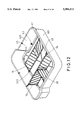
- FIG. 1 is a perspective view of a box, with two first separate boards and two second separate boards disposed therein, in accordance with the present invention
- FIG. 2 is an exploded view of the box and the separate boards in accordance with the present invention.
- FIG. 3 is a top plan view of the box
- FIG. 4 is an exploded view of the first separate board, the second separate board and two sliding members
- FIG. 5 is a side elevational view, partly in section, of the sliding member
- FIG. 6 is a end elevational view of the sliding member
- FIG. 7 is an illustrative view to show the sliding member and a part of the box
- FIG. 8 is an illustrative view to show the sliding member engaged with the position holes of the box
- FIG. 9 is an exploded view of the first separate board and the second separate board
- FIG. 10 is a perspective view to show the engagement between the first separate board and the second separate board
- FIG. 11 is a perspective view of the box wherein a second separate board is pivoted to adjacent to a first separate board;
- FIG. 12 is a perspective view of the box wherein the first separate board is pivoted to lie on the bottom of the box, and
- FIG. 13 is a perspective view of the box wherein the two first separate boards both lie on the bottom of the box.
- a box in accordance with the present invention generally includes a bottom 40, two opposite first walls 401 and two opposite second walls 402 wherein the first walls 401 and the second walls 402 extend upwardly from the bottom 40 which has two slits 405 defined therein.
- Each of the first walls 401 and the second walls 402 has a flange 41 extending transversely from an upper edge thereof.
- Each of the first walls 401 has two protrusions 403 extending from an inner peripheral surface thereof and each of the protrusions 403 has a first hole 4031 defined in a distal end thereof.
- Each of the first walls 401 and the second walls 402 has two first position holes 44 defined therein near the upper edge thereof, a second position hole 45 defined in the flange 41 and located corresponding to the first position hole 44.
- Each of the second walls 402 has two rails 42 extending from an inner peripheral surface thereof.
- Two first separate boards 10 each have two ends, an upper edge and a lower edge, each of the two ends thereof having a stud 11 extending longitudinally from a lower portion thereof for being received in the first hole 4031 of the corresponding protrusion 403.
- Each of the first separate board 10 has a plurality of loop elements 13 disposed to each one of two sides thereof and located to a middle part of the first separate board 10.
- Each one of two ends of the upper edge of the first separate board 10 has a first lower surface 101 formed therein and each of the first lower surfaces 101 has a first plate 31 extending upwardly therefrom.
- a semicircular resilient member 32 is disposed to an upper side of the first plate 31 and a first boss 320 extending upwardly from the resilient member 32.
- a first wing part 33 extends laterally from each one of two sides of the first plate 31.
- a sliding member 34 has two side walls 340, a rear wall 346 connected to the two side walls 340 and, a resilient upper cap 342 extending from the rear wall 346 and an open bottom for receiving the first plate 31 therefrom such that the sliding member 34 can be slid along the first plate 31.
- Each of the two side walls 340 has a slot 341 defined therein for receiving the corresponding first wing part 33 therein, the upper cap 342 having an engaging portion formed thereto which includes a shoulder portion 343 extending from the resilient upper cap 342 and a nose portion 344 extending from a distal end of the resilient upper cap 342 wherein a distance is defined between the shoulder portion 343 and the nose portion 344.
- the resilient upper cap 342 has two recesses 345 defined in an under side thereof for receiving the first boss 320 of the first plate 31 when the sliding member 34 is slidably disposed to the first plate 31.
- the first separate board 10 when the first separate board 10 is disposed in the box, the two studs 11 are respectively received in the first holes 4031 of the corresponding protrusions 403 and the first separate board 10 has two inserting plates 12 extending downwardly from the lower edge thereof so as to insert the inserting plates 12 into the slits 405 of the bottom 40.
- the sliding member 34 is slid toward the first wall 401 corresponding thereto and the nose portion 344 is inserted through the first position hole 44 and then is engaged with the second position hole 45 wherein the first boss 320 is received in the recess 345 near the rear wall 346, the first separate board is thereby securely positioned.
- two second separate boards 20 each have two ends, an upper edge and a lower edge, the second separate board 20 having a plurality of hooks 21 disposed to one of two ends thereof so as to hook the hooks 21 to the loop elements 13 of the first separate board 10.
- the other end of the second separate board 20 is inserted a groove defined between the two rails 42.
- each of the second separate boards 20 has a second lower surface 201 formed to an upper edge of the other end thereof, the second lower surface 201 having a second plate 202 extending upwardly therefrom, a semi-circular resilient member 203 disposed to an upper side of the second plate 202 and a second boss 204 extending upwardly from the resilient member 203.
- a second wing part 205 extends laterally from each one of two sides of the second plate 202.
- Another sliding member 34 is slidably disposed to the second plate 202 and is engaged to the second position hole 45 of the second wall 402 by the same operations as the sliding member 34 used on the first separate board 10.
- the second separate board 20 can be pivoted about an axis of the hooks 21 to disposed adjacent the first separate board 10 to change the space separated by the first and the second separate boards 10, 20.
- the first separate board 10 is able to pivoted about an axis connected between the two protrusions 403 to lie on the bottom 40 as shown in FIG. 12 or if needed, the two first separate boards 10 can be disposed to lie one the bottom 40 as shown in FIG. 13.
- the box in accordance with the present invention provides a driver to put his/her goods with a efficient and reliable way which prevent the goods from being damaged due to am impact in a car trunk.
Abstract
A box disposed in a car trunk includes a bottom, two opposite first walls and two opposite second walls, the bottom having at least one slit defined therein, each of two first walls having a protrusion extending from an inner peripheral surface thereof and the protrusion having a first hole defined in a distal end thereof for a first separate board pivotally engaged between the two protrusions wherein the first separate board is positioned by inserting an inserting plate extending from an lower edge of the first separate board into the slit, each of the first walls and the second walls having a flange extending transversely from an upper edge thereof and a first position hole defined in the second walls near the flange and a second position hole defined in the flange corresponding the first position hole, a sliding member disposed to each of two ends of the first separate board and engaged with the second position hole via the first position hole, at least one second separate board disposed between the second wall and the first separate board, the second separate board having a plurality of hooks disposed to one end thereof so as to hook to a plurality of loops disposed to a middle portion of the first separate board and the other end of the second separate board received in a groove defined in the second walls.
Description
1. Field of the Invention
The present invention relates to a box and more particularly, to a box disposed in a trunk and having a plurality of separate boards disposed therein so as to suitably receive goods in the box.
2. Brief Description of the Prior Art
Most of cars have a trunk disposed in rear end of the car and the trunk is simply a space covered by a trunk cover, the trunk is designed for receiving luggage or goods therein. However, because the trunk provides simply an empty space such that when a user puts goods bought from a supermarket into the trunk, the goods may include different shapes of packs, bottles or bags and there is no suitable position means to secure the goods in position, impact between goods may happen to contaminate or even to damage the goods.
The present invention intends to provide a box disposed in the trunk and the box has a plurality of separate boards selectably disposed therein such that goods can be put in a limited and controlled space separated by the separate boards so as to mitigate and/or obviate the above-mentioned problems.
The present invention provides a box disposed in a car trunk and the box includes a bottom, two opposite first walls and two opposite second walls wherein the first walls and the second walls extend upwardly from the bottom. Each of the first walls and the second walls has a flange extending transversely from an upper edge thereof. Each of the two first walls has at least one protrusion extending from an inner peripheral surface thereof and each of the protrusions has a first hole defined in a distal end thereof. Each of the first walls and the second walls has at least one first position hole defined therein near the upper edge thereof, a second position hole defined in the flange corresponding to the first position hole.
At least one first separate board which has two ends, an upper edge and a lower edge, each of the two ends thereof having a stud extending longitudinally therefrom for being received in the first hole of the corresponding protrusion. Each one of two ends of the upper edge of the first separate board has a first lower surface formed therein and each of the first lower surfaces has a first plate extending upwardly therefrom, a first boss extending upwardly from the first plate and a first wing part extending laterally from each one of two sides of the first plate.
A sliding member has two side walls, a rear wall connected to the two side walls, a resilient upper cap extending from the rear wall and an open bottom for receiving the first plate therefrom. Each of the two side walls has a slot defined therein for receiving the corresponding first wing part therein, the upper cap having an engaging portion formed thereto so as to be engaged with the second position hole via the first position hole.
A second separate board is disposed between the first separate board and the second wall.
It is an object of the present invention to provide a box disposed in a car trunk and the box has first separate boards and second separate boards disposed therein so as to receive goods in the a controlled space defined by separate boards and prevent goods from being damaged due to an impact therebetween.
Other objects, advantages, and novel features of the invention will become more apparent from the following detailed description when taken in conjunction with the accompanying drawings.
FIG. 1 is a perspective view of a box, with two first separate boards and two second separate boards disposed therein, in accordance with the present invention;
FIG. 2 is an exploded view of the box and the separate boards in accordance with the present invention;
FIG. 3 is a top plan view of the box;
FIG. 4 is an exploded view of the first separate board, the second separate board and two sliding members;
FIG. 5 is a side elevational view, partly in section, of the sliding member;
FIG. 6 is a end elevational view of the sliding member;
FIG. 7 is an illustrative view to show the sliding member and a part of the box; FIG. 8 is an illustrative view to show the sliding member engaged with the position holes of the box;
FIG. 9 is an exploded view of the first separate board and the second separate board;
FIG. 10 is a perspective view to show the engagement between the first separate board and the second separate board;
FIG. 11 is a perspective view of the box wherein a second separate board is pivoted to adjacent to a first separate board;
FIG. 12 is a perspective view of the box wherein the first separate board is pivoted to lie on the bottom of the box, and
FIG. 13 is a perspective view of the box wherein the two first separate boards both lie on the bottom of the box.
Referring to the drawings and initially to FIGS. 1 through 3, a box in accordance with the present invention generally includes a bottom 40, two opposite first walls 401 and two opposite second walls 402 wherein the first walls 401 and the second walls 402 extend upwardly from the bottom 40 which has two slits 405 defined therein. Each of the first walls 401 and the second walls 402 has a flange 41 extending transversely from an upper edge thereof. Each of the first walls 401 has two protrusions 403 extending from an inner peripheral surface thereof and each of the protrusions 403 has a first hole 4031 defined in a distal end thereof. Each of the first walls 401 and the second walls 402 has two first position holes 44 defined therein near the upper edge thereof, a second position hole 45 defined in the flange 41 and located corresponding to the first position hole 44. Each of the second walls 402 has two rails 42 extending from an inner peripheral surface thereof.
Two first separate boards 10 each have two ends, an upper edge and a lower edge, each of the two ends thereof having a stud 11 extending longitudinally from a lower portion thereof for being received in the first hole 4031 of the corresponding protrusion 403. Each of the first separate board 10 has a plurality of loop elements 13 disposed to each one of two sides thereof and located to a middle part of the first separate board 10. Each one of two ends of the upper edge of the first separate board 10 has a first lower surface 101 formed therein and each of the first lower surfaces 101 has a first plate 31 extending upwardly therefrom. A semicircular resilient member 32 is disposed to an upper side of the first plate 31 and a first boss 320 extending upwardly from the resilient member 32. A first wing part 33 extends laterally from each one of two sides of the first plate 31.
Referring to FIGS. 4, 5 and 6, a sliding member 34 has two side walls 340, a rear wall 346 connected to the two side walls 340 and, a resilient upper cap 342 extending from the rear wall 346 and an open bottom for receiving the first plate 31 therefrom such that the sliding member 34 can be slid along the first plate 31. Each of the two side walls 340 has a slot 341 defined therein for receiving the corresponding first wing part 33 therein, the upper cap 342 having an engaging portion formed thereto which includes a shoulder portion 343 extending from the resilient upper cap 342 and a nose portion 344 extending from a distal end of the resilient upper cap 342 wherein a distance is defined between the shoulder portion 343 and the nose portion 344. The resilient upper cap 342 has two recesses 345 defined in an under side thereof for receiving the first boss 320 of the first plate 31 when the sliding member 34 is slidably disposed to the first plate 31.
Referring further to FIGS. 7 and 8, when the first separate board 10 is disposed in the box, the two studs 11 are respectively received in the first holes 4031 of the corresponding protrusions 403 and the first separate board 10 has two inserting plates 12 extending downwardly from the lower edge thereof so as to insert the inserting plates 12 into the slits 405 of the bottom 40. The sliding member 34 is slid toward the first wall 401 corresponding thereto and the nose portion 344 is inserted through the first position hole 44 and then is engaged with the second position hole 45 wherein the first boss 320 is received in the recess 345 near the rear wall 346, the first separate board is thereby securely positioned.
Referring to FIGS. 2, 4, 9 and 10, two second separate boards 20 each have two ends, an upper edge and a lower edge, the second separate board 20 having a plurality of hooks 21 disposed to one of two ends thereof so as to hook the hooks 21 to the loop elements 13 of the first separate board 10. The other end of the second separate board 20 is inserted a groove defined between the two rails 42. Furthermore, each of the second separate boards 20 has a second lower surface 201 formed to an upper edge of the other end thereof, the second lower surface 201 having a second plate 202 extending upwardly therefrom, a semi-circular resilient member 203 disposed to an upper side of the second plate 202 and a second boss 204 extending upwardly from the resilient member 203. A second wing part 205 extends laterally from each one of two sides of the second plate 202. Another sliding member 34 is slidably disposed to the second plate 202 and is engaged to the second position hole 45 of the second wall 402 by the same operations as the sliding member 34 used on the first separate board 10.
Referring now to FIG. 11, the second separate board 20 can be pivoted about an axis of the hooks 21 to disposed adjacent the first separate board 10 to change the space separated by the first and the second separate boards 10, 20. The first separate board 10 is able to pivoted about an axis connected between the two protrusions 403 to lie on the bottom 40 as shown in FIG. 12 or if needed, the two first separate boards 10 can be disposed to lie one the bottom 40 as shown in FIG. 13.
Accordingly, the box in accordance with the present invention provides a driver to put his/her goods with a efficient and reliable way which prevent the goods from being damaged due to am impact in a car trunk.
Although the invention has been explained in relation to its preferred embodiment, it is to be understood that many other possible modifications and variations can be made without departing from the spirit and scope of the invention as hereinafter claimed.
Claims (6)
1. A box disposed in a car trunk and comprising:
a bottom, two opposite first walls and two opposite second walls wherein said first walls and said second walls extend upwardly from said bottom, each of said first walls and said second walls having a flange extending transversely from an upper edge thereof, each of said first walls having at least one protrusion extending from an inner peripheral surface thereof and each of said protrusions having a first hole defined in a distal end thereof, each of said first wails and said second walls having at least one first position hole defined therein near said upper edge thereof, a second position hole defined in said flange and located corresponding to said first position hole;
at least one first separate board having two ends, an upper edge and a lower edge, each of said two ends thereof having a stud extending longitudinally therefrom for being received in said first hole of said corresponding protrusion, each one of two ends of said upper edge of said first separate board having a first lower surface formed therein and each of said first lower surfaces having a first plate extending upwardly therefrom, a first boss extending upwardly from said first plate and a first wing part extending laterally from each one of two sides of said first plate, and
a sliding member having two side walls, a rear wall connected to said two side walls, a resilient upper cap extending from said rear wall and an open bottom for receiving said first plate therefrom, each of said two side walls having a slot defined therein for receiving said corresponding first wing part therein, said resilient upper cap having an engaging portion formed thereto so as to be engaged with said second position hole via said first position hole.
2. The box as claimed in claim 1 wherein said bottom of said box has at least one slit defined therein and said first separate board has an inserting plate extending downwardly from said lower edge thereof so as to be inserted into said slit.
3. The box as claimed in claim 1 further comprises at least one second separate board, said second separate board having two ends, an upper edge and a lower edge, said second separate board having a plurality of hooks disposed to one of two ends thereof and said first separate board having a plurality of loop elements disposed to each one of two sides thereof such that said second separate board is engaged to said first separate board by hooking said hooks to said loop elements of said first separate board.
4. The box as claimed in claim 3 wherein said second separate board has a second lower surface formed to an upper edge of the other end thereof, said second lower surface having a second plate extending upwardly therefrom, a second boss extending upwardly from said second plate and a second wing part extending laterally from each one of two sides of said second plate.
5. The box as claimed in claim 1 or 3 wherein each of said second walls of said box has at least two rails extending from an inner peripheral surface thereof so as to receive said second separate board in a groove defined between said two rails.
6. The box as claimed in claim 1 wherein said resilient upper cap has two recesses defined in an under side thereof for receiving said first boss of said first plate.
Priority Applications (1)
| Application Number | Priority Date | Filing Date | Title |
|---|---|---|---|
| US08/641,421 US5584412A (en) | 1996-05-01 | 1996-05-01 | Box disposed in a car trunk |
Applications Claiming Priority (1)
| Application Number | Priority Date | Filing Date | Title |
|---|---|---|---|
| US08/641,421 US5584412A (en) | 1996-05-01 | 1996-05-01 | Box disposed in a car trunk |
Publications (1)
| Publication Number | Publication Date |
|---|---|
| US5584412A true US5584412A (en) | 1996-12-17 |
Family
ID=24572305
Family Applications (1)
| Application Number | Title | Priority Date | Filing Date |
|---|---|---|---|
| US08/641,421 Expired - Fee Related US5584412A (en) | 1996-05-01 | 1996-05-01 | Box disposed in a car trunk |
Country Status (1)
| Country | Link |
|---|---|
| US (1) | US5584412A (en) |
Cited By (77)
| Publication number | Priority date | Publication date | Assignee | Title |
|---|---|---|---|---|
| GB2316053A (en) * | 1996-08-09 | 1998-02-18 | Kevin Burgess | Space divider |
| US5749616A (en) * | 1996-10-30 | 1998-05-12 | Thomas Body Parts, Inc. | Hose bed divider for a fire truck |
| USD419951S (en) * | 1999-03-08 | 2000-02-01 | Penda Corporation | Truck bed tray |
| WO2000021794A1 (en) * | 1998-10-13 | 2000-04-20 | Neocon International Inc. | Vehicle cargo compartment liner |
| US6109847A (en) * | 1997-10-28 | 2000-08-29 | Peregrine Incorporated | Organizer for vehicle cargo areas |
| US6231099B1 (en) | 1999-10-15 | 2001-05-15 | Delphi Technologies, Inc. | Reconfigurable glove box bin |
| US6268564B1 (en) * | 1998-03-18 | 2001-07-31 | Yazaki Corporation | Connector fixing construction of connector bracket |
| EP1321335A1 (en) | 2001-12-20 | 2003-06-25 | Renault s.a.s. | Carpet for vehicle |
| US6752304B1 (en) * | 1999-07-07 | 2004-06-22 | Johnson Controls Technology Company | Rear cargo storage assembly |
| US6763985B1 (en) * | 2000-08-11 | 2004-07-20 | Newlyn Stephenson, Sr. | Truck bed cargo stabilizer and organizer apparatus |
| US20060022004A1 (en) * | 2004-08-02 | 2006-02-02 | Mazzone Thomas J | Platform for automobile trunks |
| US20060056742A1 (en) * | 2004-09-04 | 2006-03-16 | Fenster David S | Collapsible container with drainage opening |
| US20060065560A1 (en) * | 2004-09-30 | 2006-03-30 | Tom Dickinson | Reversible gun rest |
| US20060108368A1 (en) * | 2004-10-13 | 2006-05-25 | Claude Dube | Storing container |
| US20060169701A1 (en) * | 2005-02-01 | 2006-08-03 | Meissen Cynthia R | Storage container |
| EP1690739A1 (en) * | 2005-02-14 | 2006-08-16 | Novetud | Liner tray for vehicle boot for motor vehicles or the like |
| US20060250062A1 (en) * | 2005-05-06 | 2006-11-09 | Janda Timothy M | Movable divider for a refrigerated drawer |
| US20070007787A1 (en) * | 2005-07-05 | 2007-01-11 | Hyundai Mobis Co., Ltd. | Vehicle glove box having a rotary-type partition |
| US20070051728A1 (en) * | 2005-09-06 | 2007-03-08 | Bradford Company | Container with locking strips |
| US20070095826A1 (en) * | 2005-10-27 | 2007-05-03 | Truong Thai V | Collapsible Cargo Organizer |
| EP1845024A1 (en) * | 2006-04-13 | 2007-10-17 | BITO-LAGERTECHNIK BITTMANN GmbH | Compartment division arrangement for dividing the interior of a container |
| WO2008013574A2 (en) * | 2006-07-27 | 2008-01-31 | Norseman Plastics Ltd. | Tray with drain channels and scalloped handles |
| US20080074013A1 (en) * | 2006-09-06 | 2008-03-27 | Target Brands, Inc. | Storage and organization system and components thereof |
| US20080099500A1 (en) * | 2006-10-30 | 2008-05-01 | Horst-Werner Maier-Hunke | Sheet material dispenser |
| US20080302843A1 (en) * | 2004-07-28 | 2008-12-11 | Kaneka Corporation | Automotive Luggage Box |
| US20090014019A1 (en) * | 2007-07-09 | 2009-01-15 | Park Keith K | Humidor |
| DE102008005618A1 (en) | 2008-01-23 | 2009-07-30 | GM Global Technology Operations, Inc., Detroit | Oddments tray for use in glove compartment of vehicle i.e. passenger car, has spring unit for pre-stressing separating element toward one position, and removable locking unit for locking separating element in another position |
| US20090294585A1 (en) * | 2008-05-30 | 2009-12-03 | Airbus Deutschland Gmbh | Assembly for storing objects in the cabin of a vehicle |
| US20100138206A1 (en) * | 2005-04-22 | 2010-06-03 | Syngenta Participations Ag | Methods, systems, and computer program products for producing theoretical mass spectral fragmentation patterns of chemical structures |
| US20100237754A1 (en) * | 2009-03-17 | 2010-09-23 | Target Brands, Inc. | Storage and organization system with stackable shells |
| US20100270821A1 (en) * | 2009-04-23 | 2010-10-28 | Greg Ulita | Vehicle Trunk Compartment Cargo Management System |
| US20110220655A1 (en) * | 2010-03-12 | 2011-09-15 | Simplehuman, Llc | Trash can |
| US20120037520A1 (en) * | 2010-08-13 | 2012-02-16 | Larry Robert Cline | School desk organizer |
| USD663118S1 (en) | 2009-03-17 | 2012-07-10 | Target Brands, Inc. | Storage unit |
| DE102011111332A1 (en) * | 2011-08-23 | 2013-02-28 | GM Global Technology Operations LLC (n. d. Gesetzen des Staates Delaware) | Loading system for load of motor car, has load units including plug systems, where one of load units is formed as load bay floor arranged in connection assembly in position or connecting assembly in another position |
| US20130105489A1 (en) * | 2011-10-27 | 2013-05-02 | Rubbermaid Incorporated | Container with divider |
| US20140062272A1 (en) * | 2012-08-31 | 2014-03-06 | Hon Hai Precision Industry Co., Ltd. | Electronic device |
| US8807355B2 (en) * | 2011-06-28 | 2014-08-19 | Thomas B. Merey | Expandible container |
| US20150022071A1 (en) * | 2013-07-16 | 2015-01-22 | Hon Hai Precision Industry Co., Ltd. | Bracket supporting apparatus of vending machine |
| USD730008S1 (en) | 2014-03-12 | 2015-05-19 | Simplehuman, Llc | Trash can |
| US9051093B2 (en) | 2013-03-01 | 2015-06-09 | Simplehuman, Llc | Receptacle with motion damper near lid |
| US20150203046A1 (en) * | 2014-01-22 | 2015-07-23 | Ford Global Technologies, Llc | Multi-function automotive trunk storage drawer |
| US20160059791A1 (en) * | 2014-09-02 | 2016-03-03 | Hyundai Motor Company | Variable partition apparatus for trunk of vehicle |
| US20160129482A1 (en) * | 2014-11-11 | 2016-05-12 | Boe Technology Group Co., Ltd. | Glass substrate detergent tank and cleaning device |
| USD759934S1 (en) | 2015-03-05 | 2016-06-21 | Simplehuman, Llc | Trash can trim component |
| US9481515B2 (en) | 2012-03-09 | 2016-11-01 | Simplehuman, Llc | Trash cans with features to aid in actuation |
| USD771344S1 (en) | 2015-03-05 | 2016-11-08 | Simplehuman, Llc | Trash can |
| US20160347503A1 (en) * | 2015-05-29 | 2016-12-01 | Sam Tung Tsui | Collapsible Heatable Liquid Containers |
| US9573759B2 (en) | 2007-03-09 | 2017-02-21 | Simplehuman, Llc | Trash can |
| US9586755B1 (en) | 2014-03-14 | 2017-03-07 | Simplehuman, Llc | Dual sensing receptacles |
| CN106627386A (en) * | 2016-09-28 | 2017-05-10 | 东莞市联洲知识产权运营管理有限公司 | New energy automobile trunk with separation device |
| USD793642S1 (en) | 2016-03-04 | 2017-08-01 | Simplehuman, Llc | Trash can |
| USD798016S1 (en) | 2016-03-04 | 2017-09-19 | Simplehuman, Llc | Trash can |
| US9790025B2 (en) | 2012-03-09 | 2017-10-17 | Simplehuman, Llc | Trash can with clutch mechanism |
| US20170320442A1 (en) * | 2016-05-09 | 2017-11-09 | Ford Global Technologies, Llc | Article storage device in a vehicle |
| USD804133S1 (en) | 2015-12-09 | 2017-11-28 | Simplehuman, Llc | Trash can |
| US9856080B2 (en) | 2014-03-14 | 2018-01-02 | Simplehuman, Llc | Containers with multiple sensors |
| USD813776S1 (en) * | 2016-12-07 | 2018-03-27 | Eduardo Jaimes | Cargo liner |
| FR3062583A1 (en) * | 2017-02-07 | 2018-08-10 | Thierry Leroy | IMPROVEMENT FURNITURE SORTING |
| USD835376S1 (en) | 2016-11-14 | 2018-12-04 | Simplehuman, Llc | Trash can |
| US10150420B2 (en) * | 2017-03-21 | 2018-12-11 | Ford Global Technologies, Llc | Doors off storage |
| USD839647S1 (en) * | 2012-08-30 | 2019-02-05 | Bsh Home Appliances Corporation | Drawer divider |
| US10279996B2 (en) | 2011-09-16 | 2019-05-07 | Simplehuman, Llc | Receptacle with low friction and low noise motion damper for lid |
| US10279997B2 (en) | 2014-03-14 | 2019-05-07 | Simplehuman, Llc | Trash can assembly |
| US20190184904A1 (en) * | 2017-12-14 | 2019-06-20 | Anhui Marretoo Auto Accessory Co., Ltd. | Pickup truck storage box |
| USD855919S1 (en) | 2017-06-22 | 2019-08-06 | Simplehuman, Llc | Trash can |
| USD858024S1 (en) | 2018-01-12 | 2019-08-27 | Simplehuman, Llc | Trash can |
| USD858923S1 (en) | 2018-01-12 | 2019-09-03 | Simplehuman, Llc | Trash can |
| US10494175B2 (en) | 2016-03-03 | 2019-12-03 | Simplehuman, Llc | Receptacle assemblies with motion dampers |
| US10723549B2 (en) | 2014-10-01 | 2020-07-28 | Simplehuman, Llc | Trash cans with adaptive dampening |
| USD901815S1 (en) | 2019-05-16 | 2020-11-10 | Simplehuman, Llc | Slim trash can |
| US11109704B2 (en) * | 2018-11-09 | 2021-09-07 | Kiki Business Ventures, Llc | Baby accessory storage assembly |
| US11242198B2 (en) | 2015-11-10 | 2022-02-08 | Simplehuman, Llc | Household goods with antimicrobial coatings and methods of making thereof |
| USD963277S1 (en) | 2020-08-26 | 2022-09-06 | Simplehuman, Llc | Waste receptacle |
| USD969291S1 (en) | 2020-08-26 | 2022-11-08 | Simplehuman, Llc | Odor pod |
| US11535449B2 (en) | 2018-03-07 | 2022-12-27 | Simplehuman, Llc | Trash can assembly |
| DE102022107330A1 (en) | 2022-03-29 | 2023-10-05 | Bayerische Motoren Werke Aktiengesellschaft | Container for a luggage compartment of a vehicle |
Citations (8)
| Publication number | Priority date | Publication date | Assignee | Title |
|---|---|---|---|---|
| US1116184A (en) * | 1913-12-18 | 1914-11-03 | Yawman & Erbe Mfg Co | Follower for filing-receptacles. |
| US1677544A (en) * | 1926-07-12 | 1928-07-17 | Gen Fireproofing Co | Adjustable-compartment metal drawer |
| US1799831A (en) * | 1929-05-22 | 1931-04-07 | Peter C Pauls | Adjustable springboard for dough troughs |
| US1948935A (en) * | 1931-04-14 | 1934-02-27 | Remington Rand Inc | Follower for filing devices |
| US3710974A (en) * | 1970-10-07 | 1973-01-16 | Gen Fireproofing Co | Drawer divider |
| US4261465A (en) * | 1979-08-29 | 1981-04-14 | C. R. Daniels, Inc. | Tote box for carrying different length circuit boards |
| US4358035A (en) * | 1979-07-02 | 1982-11-09 | Hanns Heidecker | Systems for holding small articles in a load compartment |
| US5381940A (en) * | 1990-04-23 | 1995-01-17 | Durakon Industries, Inc. | Tray combinations |
-
1996
- 1996-05-01 US US08/641,421 patent/US5584412A/en not_active Expired - Fee Related
Patent Citations (8)
| Publication number | Priority date | Publication date | Assignee | Title |
|---|---|---|---|---|
| US1116184A (en) * | 1913-12-18 | 1914-11-03 | Yawman & Erbe Mfg Co | Follower for filing-receptacles. |
| US1677544A (en) * | 1926-07-12 | 1928-07-17 | Gen Fireproofing Co | Adjustable-compartment metal drawer |
| US1799831A (en) * | 1929-05-22 | 1931-04-07 | Peter C Pauls | Adjustable springboard for dough troughs |
| US1948935A (en) * | 1931-04-14 | 1934-02-27 | Remington Rand Inc | Follower for filing devices |
| US3710974A (en) * | 1970-10-07 | 1973-01-16 | Gen Fireproofing Co | Drawer divider |
| US4358035A (en) * | 1979-07-02 | 1982-11-09 | Hanns Heidecker | Systems for holding small articles in a load compartment |
| US4261465A (en) * | 1979-08-29 | 1981-04-14 | C. R. Daniels, Inc. | Tote box for carrying different length circuit boards |
| US5381940A (en) * | 1990-04-23 | 1995-01-17 | Durakon Industries, Inc. | Tray combinations |
Cited By (122)
| Publication number | Priority date | Publication date | Assignee | Title |
|---|---|---|---|---|
| GB2316053A (en) * | 1996-08-09 | 1998-02-18 | Kevin Burgess | Space divider |
| US5749616A (en) * | 1996-10-30 | 1998-05-12 | Thomas Body Parts, Inc. | Hose bed divider for a fire truck |
| US6109847A (en) * | 1997-10-28 | 2000-08-29 | Peregrine Incorporated | Organizer for vehicle cargo areas |
| US6268564B1 (en) * | 1998-03-18 | 2001-07-31 | Yazaki Corporation | Connector fixing construction of connector bracket |
| WO2000021794A1 (en) * | 1998-10-13 | 2000-04-20 | Neocon International Inc. | Vehicle cargo compartment liner |
| USD419951S (en) * | 1999-03-08 | 2000-02-01 | Penda Corporation | Truck bed tray |
| US6752304B1 (en) * | 1999-07-07 | 2004-06-22 | Johnson Controls Technology Company | Rear cargo storage assembly |
| US6231099B1 (en) | 1999-10-15 | 2001-05-15 | Delphi Technologies, Inc. | Reconfigurable glove box bin |
| US6763985B1 (en) * | 2000-08-11 | 2004-07-20 | Newlyn Stephenson, Sr. | Truck bed cargo stabilizer and organizer apparatus |
| EP1321335A1 (en) | 2001-12-20 | 2003-06-25 | Renault s.a.s. | Carpet for vehicle |
| FR2833904A1 (en) * | 2001-12-20 | 2003-06-27 | Renault | RETRACTABLE STORAGE DEVICE IN A VEHICLE TRUNK |
| US20080302843A1 (en) * | 2004-07-28 | 2008-12-11 | Kaneka Corporation | Automotive Luggage Box |
| US20060022004A1 (en) * | 2004-08-02 | 2006-02-02 | Mazzone Thomas J | Platform for automobile trunks |
| US20060056742A1 (en) * | 2004-09-04 | 2006-03-16 | Fenster David S | Collapsible container with drainage opening |
| US20060065560A1 (en) * | 2004-09-30 | 2006-03-30 | Tom Dickinson | Reversible gun rest |
| US20060108368A1 (en) * | 2004-10-13 | 2006-05-25 | Claude Dube | Storing container |
| US7588162B2 (en) * | 2004-10-13 | 2009-09-15 | Rousseau Metal Inc. | Storing container |
| US20060169701A1 (en) * | 2005-02-01 | 2006-08-03 | Meissen Cynthia R | Storage container |
| EP1690739A1 (en) * | 2005-02-14 | 2006-08-16 | Novetud | Liner tray for vehicle boot for motor vehicles or the like |
| FR2882010A1 (en) * | 2005-02-14 | 2006-08-18 | Novetud Sa | BAC FOR CARRIAGE OF VEHICLE BOXES FOR MOTOR VEHICLES OR THE LIKE |
| US20100138206A1 (en) * | 2005-04-22 | 2010-06-03 | Syngenta Participations Ag | Methods, systems, and computer program products for producing theoretical mass spectral fragmentation patterns of chemical structures |
| US20060250062A1 (en) * | 2005-05-06 | 2006-11-09 | Janda Timothy M | Movable divider for a refrigerated drawer |
| US7566105B2 (en) * | 2005-05-06 | 2009-07-28 | Whirlpool Corporation | Movable divider for a refrigerated drawer |
| US20070007787A1 (en) * | 2005-07-05 | 2007-01-11 | Hyundai Mobis Co., Ltd. | Vehicle glove box having a rotary-type partition |
| US7431369B2 (en) * | 2005-07-05 | 2008-10-07 | Hyundai Mobis Co., Ltd. | Vehicle glove box having a rotary-type partition |
| US7654408B2 (en) * | 2005-09-06 | 2010-02-02 | Bradford Company | Container with locking strips |
| US20070051728A1 (en) * | 2005-09-06 | 2007-03-08 | Bradford Company | Container with locking strips |
| US7784632B2 (en) * | 2005-10-27 | 2010-08-31 | Thai Vo Truong | Collapsible cargo organizer |
| US20070095826A1 (en) * | 2005-10-27 | 2007-05-03 | Truong Thai V | Collapsible Cargo Organizer |
| EP1845024A1 (en) * | 2006-04-13 | 2007-10-17 | BITO-LAGERTECHNIK BITTMANN GmbH | Compartment division arrangement for dividing the interior of a container |
| WO2008013574A2 (en) * | 2006-07-27 | 2008-01-31 | Norseman Plastics Ltd. | Tray with drain channels and scalloped handles |
| US20080023426A1 (en) * | 2006-07-27 | 2008-01-31 | Norseman Plastics, Ltd. | Two position nestable tray with drain channels and scalloped handles |
| US8833594B2 (en) * | 2006-07-27 | 2014-09-16 | Orbis Canada Limited | Two position nestable tray with drain channels and scalloped handles |
| WO2008013574A3 (en) * | 2006-07-27 | 2008-12-04 | Norseman Plastics Ltd | Tray with drain channels and scalloped handles |
| US7866769B2 (en) * | 2006-09-06 | 2011-01-11 | Target Brands, Inc. | Storage and organization system and components thereof |
| US20080074013A1 (en) * | 2006-09-06 | 2008-03-27 | Target Brands, Inc. | Storage and organization system and components thereof |
| US20110074255A1 (en) * | 2006-09-06 | 2011-03-31 | Target Brands, Inc. | Storage bin and associated system |
| US8708433B2 (en) | 2006-09-06 | 2014-04-29 | Target Brands, Inc. | Storage and organization system and components thereof |
| US8418874B2 (en) * | 2006-09-06 | 2013-04-16 | Target Brands, Inc. | Storage bin and associated system |
| US20080099500A1 (en) * | 2006-10-30 | 2008-05-01 | Horst-Werner Maier-Hunke | Sheet material dispenser |
| US7909182B2 (en) * | 2006-10-30 | 2011-03-22 | Durable Hunke & Jochheim Gmbh & Co. Kg | Sheet material dispenser |
| US9573759B2 (en) | 2007-03-09 | 2017-02-21 | Simplehuman, Llc | Trash can |
| US20090014019A1 (en) * | 2007-07-09 | 2009-01-15 | Park Keith K | Humidor |
| DE102008005618A1 (en) | 2008-01-23 | 2009-07-30 | GM Global Technology Operations, Inc., Detroit | Oddments tray for use in glove compartment of vehicle i.e. passenger car, has spring unit for pre-stressing separating element toward one position, and removable locking unit for locking separating element in another position |
| US20090294585A1 (en) * | 2008-05-30 | 2009-12-03 | Airbus Deutschland Gmbh | Assembly for storing objects in the cabin of a vehicle |
| US9211843B2 (en) * | 2008-05-30 | 2015-12-15 | Airbus Operations Gmbh | Assembly for storing objects in the cabin of a vehicle |
| USD663118S1 (en) | 2009-03-17 | 2012-07-10 | Target Brands, Inc. | Storage unit |
| US8573716B2 (en) | 2009-03-17 | 2013-11-05 | Target Brands, Inc. | Storage and organization system and connectivity of the components therein |
| US8186776B2 (en) | 2009-03-17 | 2012-05-29 | Target Brands, Inc. | Storage and organization system and connectivity of the components therein |
| US8113600B2 (en) | 2009-03-17 | 2012-02-14 | Target Brands, Inc. | Storage and organization system with stackable shells |
| US8414092B2 (en) | 2009-03-17 | 2013-04-09 | Target Brands, Inc. | Storage and organization system with stackable shells |
| US20100237754A1 (en) * | 2009-03-17 | 2010-09-23 | Target Brands, Inc. | Storage and organization system with stackable shells |
| US20100270821A1 (en) * | 2009-04-23 | 2010-10-28 | Greg Ulita | Vehicle Trunk Compartment Cargo Management System |
| US8215693B2 (en) * | 2009-04-23 | 2012-07-10 | Greg Ulita | Vehicle trunk compartment cargo management system |
| US9434538B2 (en) * | 2010-03-12 | 2016-09-06 | Simplehuman, Llc | Trash can |
| US20110220655A1 (en) * | 2010-03-12 | 2011-09-15 | Simplehuman, Llc | Trash can |
| US20120037520A1 (en) * | 2010-08-13 | 2012-02-16 | Larry Robert Cline | School desk organizer |
| US8807355B2 (en) * | 2011-06-28 | 2014-08-19 | Thomas B. Merey | Expandible container |
| DE102011111332A1 (en) * | 2011-08-23 | 2013-02-28 | GM Global Technology Operations LLC (n. d. Gesetzen des Staates Delaware) | Loading system for load of motor car, has load units including plug systems, where one of load units is formed as load bay floor arranged in connection assembly in position or connecting assembly in another position |
| US10279996B2 (en) | 2011-09-16 | 2019-05-07 | Simplehuman, Llc | Receptacle with low friction and low noise motion damper for lid |
| US20130105489A1 (en) * | 2011-10-27 | 2013-05-02 | Rubbermaid Incorporated | Container with divider |
| US8727172B2 (en) * | 2011-10-27 | 2014-05-20 | Rubbermaid Incorporated | Container with divider |
| US10683165B2 (en) | 2012-03-09 | 2020-06-16 | Simplehuman, Llc | Trash can assembly |
| US11136186B2 (en) | 2012-03-09 | 2021-10-05 | Simplehuman, Llc | Trash can assembly |
| US11603263B2 (en) | 2012-03-09 | 2023-03-14 | Simplehuman, Llc | Trash can assembly |
| US9790025B2 (en) | 2012-03-09 | 2017-10-17 | Simplehuman, Llc | Trash can with clutch mechanism |
| US9481515B2 (en) | 2012-03-09 | 2016-11-01 | Simplehuman, Llc | Trash cans with features to aid in actuation |
| USD839647S1 (en) * | 2012-08-30 | 2019-02-05 | Bsh Home Appliances Corporation | Drawer divider |
| US8931858B2 (en) * | 2012-08-31 | 2015-01-13 | ScienBiziP Consulting(Shenzhen)Co., Ltd. | Electronic device |
| US20140062272A1 (en) * | 2012-08-31 | 2014-03-06 | Hon Hai Precision Industry Co., Ltd. | Electronic device |
| US9051093B2 (en) | 2013-03-01 | 2015-06-09 | Simplehuman, Llc | Receptacle with motion damper near lid |
| US20150022071A1 (en) * | 2013-07-16 | 2015-01-22 | Hon Hai Precision Industry Co., Ltd. | Bracket supporting apparatus of vending machine |
| US9630562B2 (en) | 2014-01-22 | 2017-04-25 | Ford Global Technologies, Llc | Multi-function automotive trunk storage drawer |
| US9321402B2 (en) * | 2014-01-22 | 2016-04-26 | Ford Global Technologies, Llc | Multi-function automotive trunk storage drawer |
| US20150203046A1 (en) * | 2014-01-22 | 2015-07-23 | Ford Global Technologies, Llc | Multi-function automotive trunk storage drawer |
| USD730008S1 (en) | 2014-03-12 | 2015-05-19 | Simplehuman, Llc | Trash can |
| USD930933S1 (en) | 2014-03-14 | 2021-09-14 | Simplehuman, Llc | Trash can |
| US9586755B1 (en) | 2014-03-14 | 2017-03-07 | Simplehuman, Llc | Dual sensing receptacles |
| US11801996B2 (en) | 2014-03-14 | 2023-10-31 | Simplehuman, Llc | Trash can assembly |
| US9751692B2 (en) | 2014-03-14 | 2017-09-05 | Simplehuman, Llc | Dual sensing receptacles |
| US11027916B2 (en) | 2014-03-14 | 2021-06-08 | Simplehuman, Llc | Containers with multiple sensors |
| US10472170B2 (en) | 2014-03-14 | 2019-11-12 | Simplehuman, Llc | Containers with multiple sensors |
| US9856080B2 (en) | 2014-03-14 | 2018-01-02 | Simplehuman, Llc | Containers with multiple sensors |
| US10279997B2 (en) | 2014-03-14 | 2019-05-07 | Simplehuman, Llc | Trash can assembly |
| US20160059791A1 (en) * | 2014-09-02 | 2016-03-03 | Hyundai Motor Company | Variable partition apparatus for trunk of vehicle |
| US9925925B2 (en) * | 2014-09-02 | 2018-03-27 | Hyundai Motor Company | Variable partition apparatus for trunk of vehicle |
| US10723549B2 (en) | 2014-10-01 | 2020-07-28 | Simplehuman, Llc | Trash cans with adaptive dampening |
| US20160129482A1 (en) * | 2014-11-11 | 2016-05-12 | Boe Technology Group Co., Ltd. | Glass substrate detergent tank and cleaning device |
| US9993850B2 (en) * | 2014-11-11 | 2018-06-12 | Boe Technology Group Co., Ltd. | Glass substrate detergent tank and cleaning device |
| USD773145S1 (en) | 2015-03-05 | 2016-11-29 | Simplehuman, Llc | Trash can |
| USD771344S1 (en) | 2015-03-05 | 2016-11-08 | Simplehuman, Llc | Trash can |
| USD759934S1 (en) | 2015-03-05 | 2016-06-21 | Simplehuman, Llc | Trash can trim component |
| US20160347503A1 (en) * | 2015-05-29 | 2016-12-01 | Sam Tung Tsui | Collapsible Heatable Liquid Containers |
| US10464711B2 (en) * | 2015-05-29 | 2019-11-05 | Sam Tung Tsui | Collapsible heatable liquid containers |
| US11242198B2 (en) | 2015-11-10 | 2022-02-08 | Simplehuman, Llc | Household goods with antimicrobial coatings and methods of making thereof |
| USD804133S1 (en) | 2015-12-09 | 2017-11-28 | Simplehuman, Llc | Trash can |
| USD829400S1 (en) | 2015-12-09 | 2018-09-25 | Simplehuman, Llc | Trash can |
| US11279555B2 (en) | 2016-03-03 | 2022-03-22 | Simplehuman, Llc | Receptacle assemblies with motion dampers |
| US10494175B2 (en) | 2016-03-03 | 2019-12-03 | Simplehuman, Llc | Receptacle assemblies with motion dampers |
| USD835374S1 (en) | 2016-03-04 | 2018-12-04 | Simplehuman, Llc | Trash can |
| USD793642S1 (en) | 2016-03-04 | 2017-08-01 | Simplehuman, Llc | Trash can |
| USD798016S1 (en) | 2016-03-04 | 2017-09-19 | Simplehuman, Llc | Trash can |
| US20170320442A1 (en) * | 2016-05-09 | 2017-11-09 | Ford Global Technologies, Llc | Article storage device in a vehicle |
| US10124736B2 (en) * | 2016-05-09 | 2018-11-13 | Ford Global Technologies, Llc | Article storage device in a vehicle |
| CN106627386B (en) * | 2016-09-28 | 2018-09-14 | 东莞市联洲知识产权运营管理有限公司 | A kind of boot of the new-energy automobile with separating device |
| CN106627386A (en) * | 2016-09-28 | 2017-05-10 | 东莞市联洲知识产权运营管理有限公司 | New energy automobile trunk with separation device |
| USD835376S1 (en) | 2016-11-14 | 2018-12-04 | Simplehuman, Llc | Trash can |
| USD813776S1 (en) * | 2016-12-07 | 2018-03-27 | Eduardo Jaimes | Cargo liner |
| FR3062583A1 (en) * | 2017-02-07 | 2018-08-10 | Thierry Leroy | IMPROVEMENT FURNITURE SORTING |
| WO2018146414A1 (en) * | 2017-02-07 | 2018-08-16 | Thierry Leroy | Improved furniture item for sorting objects |
| US10150420B2 (en) * | 2017-03-21 | 2018-12-11 | Ford Global Technologies, Llc | Doors off storage |
| USD855919S1 (en) | 2017-06-22 | 2019-08-06 | Simplehuman, Llc | Trash can |
| US20190184904A1 (en) * | 2017-12-14 | 2019-06-20 | Anhui Marretoo Auto Accessory Co., Ltd. | Pickup truck storage box |
| USD858923S1 (en) | 2018-01-12 | 2019-09-03 | Simplehuman, Llc | Trash can |
| USD858024S1 (en) | 2018-01-12 | 2019-08-27 | Simplehuman, Llc | Trash can |
| US11535449B2 (en) | 2018-03-07 | 2022-12-27 | Simplehuman, Llc | Trash can assembly |
| US11109704B2 (en) * | 2018-11-09 | 2021-09-07 | Kiki Business Ventures, Llc | Baby accessory storage assembly |
| USD901815S1 (en) | 2019-05-16 | 2020-11-10 | Simplehuman, Llc | Slim trash can |
| USD963277S1 (en) | 2020-08-26 | 2022-09-06 | Simplehuman, Llc | Waste receptacle |
| USD969291S1 (en) | 2020-08-26 | 2022-11-08 | Simplehuman, Llc | Odor pod |
| USD1004069S1 (en) | 2020-08-26 | 2023-11-07 | Simplehuman, Llc | Odor pod receptacle |
| DE102022107330A1 (en) | 2022-03-29 | 2023-10-05 | Bayerische Motoren Werke Aktiengesellschaft | Container for a luggage compartment of a vehicle |
Similar Documents
| Publication | Publication Date | Title |
|---|---|---|
| US5584412A (en) | Box disposed in a car trunk | |
| US4634004A (en) | Magnetic tape security housing | |
| US3463309A (en) | Reusable package | |
| US6135527A (en) | Cargo compartment organizer | |
| US5114007A (en) | Tool box with drawer member | |
| US4923153A (en) | Strip clamp | |
| US6412637B1 (en) | Food storage containers | |
| US5890648A (en) | Carton with sauce holder | |
| US6044973A (en) | Case with split panels | |
| EP0342029B1 (en) | Container | |
| US5803254A (en) | Tool case with multiple storage compartments | |
| EP2364820B1 (en) | Storage container | |
| JPS5962476A (en) | Single piece case for encasing large number of slender type tool part | |
| US4787515A (en) | Tote container with removable hinged lid and combined handgrip/stacking frame | |
| US7240778B2 (en) | Personalizing luggage | |
| US6231099B1 (en) | Reconfigurable glove box bin | |
| US3612635A (en) | Tackle box | |
| CN108202770B (en) | Storage compartment of rear railing panel | |
| US20080099485A1 (en) | Sortables storage container | |
| US5941386A (en) | Portable tool holder with theft prevention | |
| US5758769A (en) | Tool case | |
| US20020117947A1 (en) | Toolbox module | |
| US20090000975A1 (en) | File organizer with multiple dividers | |
| US5291996A (en) | Reusable display sheath with frangible latch means | |
| US5794953A (en) | Shopping cart with advertising card mount to plastic basket in improved manner |
Legal Events
| Date | Code | Title | Description |
|---|---|---|---|
| AS | Assignment |
Owner name: KUAN TONG INDUSRIAL CO., LTD., TAIWAN Free format text: ASSIGNMENT OF ASSIGNORS INTEREST;ASSIGNOR:WANG, CHU TUNG;REEL/FRAME:008017/0146 Effective date: 19960420 |
|
| REMI | Maintenance fee reminder mailed | ||
| LAPS | Lapse for failure to pay maintenance fees | ||
| FP | Lapsed due to failure to pay maintenance fee |
Effective date: 20001217 |
|
| STCH | Information on status: patent discontinuation |
Free format text: PATENT EXPIRED DUE TO NONPAYMENT OF MAINTENANCE FEES UNDER 37 CFR 1.362 |