US5576956A - Auxiliary steering angle control system for vehicle - Google Patents
Auxiliary steering angle control system for vehicle Download PDFInfo
- Publication number
- US5576956A US5576956A US08/340,403 US34040394A US5576956A US 5576956 A US5576956 A US 5576956A US 34040394 A US34040394 A US 34040394A US 5576956 A US5576956 A US 5576956A
- Authority
- US
- United States
- Prior art keywords
- vehicle
- road
- auxiliary steering
- steering angle
- condition
- Prior art date
- Legal status (The legal status is an assumption and is not a legal conclusion. Google has not performed a legal analysis and makes no representation as to the accuracy of the status listed.)
- Expired - Lifetime
Links
Images


Classifications
-
- B—PERFORMING OPERATIONS; TRANSPORTING
- B62—LAND VEHICLES FOR TRAVELLING OTHERWISE THAN ON RAILS
- B62D—MOTOR VEHICLES; TRAILERS
- B62D6/00—Arrangements for automatically controlling steering depending on driving conditions sensed and responded to, e.g. control circuits
-
- B—PERFORMING OPERATIONS; TRANSPORTING
- B62—LAND VEHICLES FOR TRAVELLING OTHERWISE THAN ON RAILS
- B62D—MOTOR VEHICLES; TRAILERS
- B62D7/00—Steering linkage; Stub axles or their mountings
- B62D7/06—Steering linkage; Stub axles or their mountings for individually-pivoted wheels, e.g. on king-pins
- B62D7/14—Steering linkage; Stub axles or their mountings for individually-pivoted wheels, e.g. on king-pins the pivotal axes being situated in more than one plane transverse to the longitudinal centre line of the vehicle, e.g. all-wheel steering
- B62D7/15—Steering linkage; Stub axles or their mountings for individually-pivoted wheels, e.g. on king-pins the pivotal axes being situated in more than one plane transverse to the longitudinal centre line of the vehicle, e.g. all-wheel steering characterised by means varying the ratio between the steering angles of the steered wheels
- B62D7/159—Steering linkage; Stub axles or their mountings for individually-pivoted wheels, e.g. on king-pins the pivotal axes being situated in more than one plane transverse to the longitudinal centre line of the vehicle, e.g. all-wheel steering characterised by means varying the ratio between the steering angles of the steered wheels characterised by computing methods or stabilisation processes or systems, e.g. responding to yaw rate, lateral wind, load, road condition
Definitions
- the present invention relates to improvements in an auxiliary steering angle control system for a wheeled vehicle, and more particularly to an auxiliary steering angle control system which executes an auxiliary steering angle control with a feedback compensation.
- Japanese Patent Provisional Publication No. 62-247979 discloses a typical auxiliary steering angle control system where an auxiliary steering control is executed by applying a feedback control and a feed-forward control to a vehicle motion variable.
- a conventional auxiliary steering angle control system is arranged to execute the feedback control during a vehicle running condition regardless of a road condition. Therefore, in case that the road condition is suddenly changed from a bad-conditioned surface such as a bumpy road to a good-conditioned surface, unexpected vehicle motion variable is occurred in the vehicle and impresses a strange feeling to a driver. That is, in case that the vehicle is traveling on an extremely bad-conditioned (bumpy) road, the tire contact area on a road surface is decreased. Accordingly, the cornering force of the tires is decreased and therefore the yaw rate generated by the steering operation becomes difficult to be change.
- Another object of the present invention is to provide an auxiliary steering angle control system which includes an advantageous road condition detecting means.
- an auxiliary steering angle control system for a vehicle comprises a vehicle condition detecting means, a desired vehicle motion variable calculating means, an actual vehicle motion variable detecting means, an auxiliary steering angle feedback control-input determining means, a road condition detecting means and an auxiliary steering feedback control-input correcting means.
- the vehicle condition detecting means detects a vehicle condition.
- the desired vehicle motion variable calculating means calculates a desired value of the vehicle motion variable actually generated to the vehicle from the detected vehicle condition.
- the actual vehicle motion variable detecting means detects an actual vehicle motion variable actually generated in the vehicle.
- the auxiliary steering angle feedback control-input determining means determines an auxiliary steering feedback control-input according to the difference between the desired vehicle motion variable and the detected actual vehicle motion variable.
- the road condition detecting means detects a road variable indicative of a condition of a road on which the vehicle is traveling.
- the auxiliary steering feedback control-input correcting means reduces the auxiliary steering angle feedback control-input when the road condition detecting means outputs a signal indicative that the vehicle is traveling on a bad-conditioned road.
- FIG. 1 is a schematic structural view of a four-wheel steering vehicle where an auxiliary steering angle control system according to the present invention is applied;
- FIG. 2 is a block diagram showing an electronic system of the control system to the present invention
- FIG. 3 is a flow chart which shows a procedure of the rear wheel steering angle control by a controller of the auxiliary steering angle control system according to the present invention
- FIG. 4 is a flow chart which shows a procedure of the calculation of a vehicle motion variable and a correction factor
- FIG. 5 is a map for obtaining the correction factor with respect to a road condition variable
- FIG. 6 is a characteristic chart of the vehicle motion variable, a generated yaw rate and a high frequency component thereof which are the result of an actual traveling of a road;
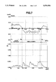
- FIG. 7 is a characteristic chart similar to that of FIG. 6 in another road condition
- FIGS. 8A and 8B are a characteristic chart of a front wheel steering angle and a yaw rate generated by disturbance which are a preset condition for a simulation of the vehicle.
- FIGS. 9A and 9B are characteristic chart which shows a result of the simulation of FIGS. 8A and 8B.
- FIG. 1 shows a schematic structural view of a wheeled vehicle WV to which the auxiliary steering control system is applied.
- the auxiliary steering angle control system for the wheeled vehicle WV such as an automotive vehicle, comprises a steering angle actuator 6, a controller 7, steering angle sensor 8, a vehicle speed sensor 9, and a yaw rate sensor 10, and a rear wheel steered angle sensor 11.
- the wheeled vehicle WV is provided with a pair of front wheels 1 and 2 which are steered by a driver through a steering wheel 8a and a mechanical link type steering device 3. Further, a pair of rear wheels 4 and 5 are steered by an electrically controlled steering angle actuator 6. Each of the wheels 1, 2, 4 and 5 is provided with a tire directly in contact with a road surface.
- the controller 7 is constituted by a micro-computer or electrical circuits.
- the controller 7 receives a signal indicative of a steering angle ⁇ of the front wheels 1 and 2 from the steering angle sensor 8, a signal indicative of a vehicle speed V from the vehicle speed sensor 9, a signal indicative of a yaw rate d ⁇ from a yaw rate sensor 10, and a signal indicative of an actual rear wheel steered angle ⁇ R.
- the controller 7 executes predetermined calculating operations for obtaining a desired auxiliary steering angle control-input ⁇ REF by which the steering angle of the rear wheels 4 and 5 are controlled.
- the controller 7 outputs a drive command to the auxiliary steering angle actuator 6 so as to set the steering angle of the rear wheels 3 and 4 to the determined steering angle.
- FIG. 2 shows a block diagram of operations executed by the controller 7.
- the controller 7 includes a desired yaw rate calculating section 21, an auxiliary steering angle feed-forward control-input calculating section 22, an auxiliary steering angle feedback control-input calculating section 23, a road condition detecting section 24, an auxiliary steering angle feedback control-input correcting section 25 and a desired auxiliary steering angle control-input calculation section 26.
- FIG. 3 shows a flow chart which shows a procedure of a rear wheel steering angle control executed by the controller 7.
- a step S101 the controller 7 judges whether a predetermined time period corresponding to a control preparing time period has elapsed or not. When an answer in the step S101 is NO, the routine repeats the step S101. When the answer is YES, the routine proceeds to a step S102 wherein the controller 7 receives the signal indicative of the steering angle ⁇ of the steering wheel 8a from the steering angle sensor 8, the signal indicative of the vehicle speed V from the vehicle speed sensor 9 and the signal indicative of the yaw rate d ⁇ from the yaw rate sensor 10.
- a step S103 the desired yaw rate calculating section 21 of the controller 7 calculates the desired yaw rate d ⁇ M functioning as a desired vehicle motion variable according to the inputted signals in the step S102.
- a step S105 the road condition detecting section 24 of the controller 7 calculates a road variable R from the generated yaw rate d ⁇ .
- the road variable R indicates a degree of a bumpiness of the road surface.
- a step S106 the road condition detecting section 24 of the controller 7 calculates a correction factor Kp for correcting the auxiliary feedback control-input ⁇ F/B by using the road variable R.
- a step S107 the auxiliary steering angle feedback control-input correcting section 25 of the controller 7 calculates the correction value ⁇ F/BM for the auxiliary steering angle control-input from the auxiliary steering angle feedback control-input ⁇ F/B and the correction factor Kp.
- the generated yaw rate d ⁇ detected by the yaw rate sensor 10 includes a lot of signals indicative of high-frequency component d ⁇ H whose degree is larger than that in case of the traveling on a well-conditioned road. Accordingly, it is possible to judge the road condition from the high-frequency component d ⁇ H of the generated yaw rate d ⁇ .
- the road condition detecting section 24 judges the road condition from the high-frequency component d ⁇ H which is extracted from the generated yaw rate d ⁇ .
- a high-pass filter which is expressed by the following equations (1) and (2) is known.
- ⁇ is a damping factor
- ⁇ n is a cut-off frequency
- s is Laplace operator
- the road condition detecting section 24 calculates the road variable R and decides the correction factor Kp according to the obtained road variable R.
- One of method for obtaining the road variable R is a so-called square-integration of d ⁇ H which is derived from the following equations.
- d ⁇ th is a threshold value
- RLMT is an upper limit of the road variable
- n is a present time
- C1 is a constant.
- a calculating method of the road variable R may be a method of filtering the square of d ⁇ H by the following equation (7):
- ⁇ is a filter time constant
- s is Laplace operator
- a value C2 is determined from the calculated road variable R and a map shown in FIG. 5. Then, the correction factor Kp for correcting the auxiliary steering angle feedback control-input dF/B is determined by the following equation.
- the above method for calculating the road variable R and the correction factor Kp is corresponding to the steps S105 and S106, and a flow chart of FIG. 4 shows a procedure thereof.
- a step S201 the controller 7 receives the generated yaw rate d ⁇ detected by the yaw rate sensor 10.
- a step S202 the controller 7 derives the high-frequency component d ⁇ H of the generated yaw rate d ⁇ from the above equations (1) and (2).
- a step S210 the correction factor Kp is determined from the road variable R calculated in one of the steps S205, S206, S208 and S209, the map shown in FIG. 5, and the equation (8).
- FIGS. 6 and 7 show characteristics charts where the generated yaw rate d ⁇ which was detected during an actual traveling of the vehicle, the high-frequency component d ⁇ H which has been filtered by a digital high-pass filter, and the road variable R calculated by the method shown in FIG. 4.
- FIGS. 6 and 7 the road condition actually traveled by the vehicle was changed as shown in the following table 1.
- FIG. 8 shows characteristic charts of a front wheel steering characteristic and the yaw rate generated by the disturbance which are a preset condition for the simulation. Further, in this simulation, it was assumed that the vehicle travels on bumpy road by which the contact area of the tires is decreased during a turning.
- FIG. 9 shows a generated yaw rate characteristic chart, a rear wheel steering angle characteristics chart, and an auxiliary steering angle feedback control-input characteristic chart.
- continuous line shows characteristics in case that the contact area of the tires to road surface is constant.
- a broken line shows a characteristic chart of a conventional method where the contact area of tires of the wheels is varied according to the road condition.
- An alternate long and short dash line shows a characteristic chart of the method according to the present invention where the contact area of the tires is varied according to the road condition.
- the result of the simulation indicates that in case the contact area of the tires is constant, it is possible to suppress the generation of the yaw rate caused by the disturbance by means of a feedback control.
- the contact area of the tires is varied by bumps on the road surface (during a period from 0.5 second point to 0.65 second point, tire contact feeling is lost)
- the feedback control is executed directly, the generated yaw rate is largely varied at a time that the contact of tires is recovered. Therefore, a driver of the vehicle receives strange feeling.
- the auxiliary steering angle feedback control-input ⁇ F/B is decreasingly corrected. Accordingly, when the tire contact is recovered, the generated yaw rate is smoothly converged into a predetermined generated yaw rate level. This prevents the generation of strange feeling.
- the road condition detecting section 24 is provided to detect the correction factor Kp for correcting the auxiliary steering angle feedback control-input ⁇ F/B
- the auxiliary steering angle feedback control-input correcting section 25 is provided to decrease the auxiliary steering angle control-input ⁇ F/B according to the road condition. Therefore, even during a road including a bad-conditioned surface, a driver of a vehicle equipped with this system can continue driving without having a strange feeling.
- the road condition detecting section 24 is arranged to detect a road variable from the degree of high-frequency component included in the detected yaw rate signal, this system according to the present invention ensures a merit in a cost.
- control system has been applied to the rear wheels, it will be understood that the invention is applicable to a front-wheel auxiliary steering control system and a four-wheel auxiliary steering control system.
- yaw rate has been used as a vehicle motion variable in the embodiment of the invention
- a lateral acceleration, a side velocity or a yaw rate plus a side velocity may be used as a vehicle motion variable.
- the auxiliary steering angle has been controlled by the feed-forward control plus feedback control, the auxiliary steering angle may be controlled only by the feedback control.
- a vertical vibration detector may be applied to a means for detecting a road condition.
Abstract
An auxiliary steering angle control system for a vehicle comprises a vehicle condition detecting section for detecting a vehicle condition, a desired motion variable calculating section for calculating a desired value of the motion variable actually generated to the vehicle from the detected vehicle condition, an actual motion variable detecting section for detecting an actual motion variable actually generated in the vehicle, an auxiliary steering angle feedback control-input determining section for determining an auxiliary steering feedback control-input according to the difference between the desired motion variable and the detected actual-vehicle motion variable, a road condition detecting section for detecting a road variable indicative of a condition of a road on which the vehicle is traveling, and an auxiliary steering feedback control-input correcting section for reducing the auxiliary steering angle feedback control-input when the road condition detecting section outputs a signal indicative that the vehicle is traveling on a bad-conditioned road.
Description
1. Field of the Invention
The present invention relates to improvements in an auxiliary steering angle control system for a wheeled vehicle, and more particularly to an auxiliary steering angle control system which executes an auxiliary steering angle control with a feedback compensation.
2. Description of the Prior Art
Various auxiliary steering angle control systems for vehicles have been proposed and in practical use. Japanese Patent Provisional Publication No. 62-247979 discloses a typical auxiliary steering angle control system where an auxiliary steering control is executed by applying a feedback control and a feed-forward control to a vehicle motion variable.
However, such a conventional auxiliary steering angle control system is arranged to execute the feedback control during a vehicle running condition regardless of a road condition. Therefore, in case that the road condition is suddenly changed from a bad-conditioned surface such as a bumpy road to a good-conditioned surface, unexpected vehicle motion variable is occurred in the vehicle and impresses a strange feeling to a driver. That is, in case that the vehicle is traveling on an extremely bad-conditioned (bumpy) road, the tire contact area on a road surface is decreased. Accordingly, the cornering force of the tires is decreased and therefore the yaw rate generated by the steering operation becomes difficult to be change.
It is an object of the present invention to provide an improved auxiliary steering angle control system which applies a suitable steering feeling to a driver even during a traveling on a road having a variously changing surface.
Another object of the present invention is to provide an auxiliary steering angle control system which includes an advantageous road condition detecting means.
According to the present invention, an auxiliary steering angle control system for a vehicle comprises a vehicle condition detecting means, a desired vehicle motion variable calculating means, an actual vehicle motion variable detecting means, an auxiliary steering angle feedback control-input determining means, a road condition detecting means and an auxiliary steering feedback control-input correcting means. The vehicle condition detecting means detects a vehicle condition. The desired vehicle motion variable calculating means calculates a desired value of the vehicle motion variable actually generated to the vehicle from the detected vehicle condition. The actual vehicle motion variable detecting means detects an actual vehicle motion variable actually generated in the vehicle. The auxiliary steering angle feedback control-input determining means determines an auxiliary steering feedback control-input according to the difference between the desired vehicle motion variable and the detected actual vehicle motion variable. The road condition detecting means detects a road variable indicative of a condition of a road on which the vehicle is traveling. The auxiliary steering feedback control-input correcting means reduces the auxiliary steering angle feedback control-input when the road condition detecting means outputs a signal indicative that the vehicle is traveling on a bad-conditioned road.
FIG. 1 is a schematic structural view of a four-wheel steering vehicle where an auxiliary steering angle control system according to the present invention is applied;
FIG. 2 is a block diagram showing an electronic system of the control system to the present invention;
FIG. 3 is a flow chart which shows a procedure of the rear wheel steering angle control by a controller of the auxiliary steering angle control system according to the present invention;
FIG. 4 is a flow chart which shows a procedure of the calculation of a vehicle motion variable and a correction factor;
FIG. 5 is a map for obtaining the correction factor with respect to a road condition variable;
FIG. 6 is a characteristic chart of the vehicle motion variable, a generated yaw rate and a high frequency component thereof which are the result of an actual traveling of a road;
FIG. 7 is a characteristic chart similar to that of FIG. 6 in another road condition;
FIGS. 8A and 8B are a characteristic chart of a front wheel steering angle and a yaw rate generated by disturbance which are a preset condition for a simulation of the vehicle; and
FIGS. 9A and 9B are characteristic chart which shows a result of the simulation of FIGS. 8A and 8B.
Referring now to FIGS. 1 to 9, there is shown an embodiment of an auxiliary steering angle control system according to the present invention. FIG. 1 shows a schematic structural view of a wheeled vehicle WV to which the auxiliary steering control system is applied.
As shown in FIG. 1, the auxiliary steering angle control system for the wheeled vehicle WV, such as an automotive vehicle, comprises a steering angle actuator 6, a controller 7, steering angle sensor 8, a vehicle speed sensor 9, and a yaw rate sensor 10, and a rear wheel steered angle sensor 11.
The wheeled vehicle WV is provided with a pair of front wheels 1 and 2 which are steered by a driver through a steering wheel 8a and a mechanical link type steering device 3. Further, a pair of rear wheels 4 and 5 are steered by an electrically controlled steering angle actuator 6. Each of the wheels 1, 2, 4 and 5 is provided with a tire directly in contact with a road surface.
The controller 7 is constituted by a micro-computer or electrical circuits. The controller 7 receives a signal indicative of a steering angle θ of the front wheels 1 and 2 from the steering angle sensor 8, a signal indicative of a vehicle speed V from the vehicle speed sensor 9, a signal indicative of a yaw rate dψ from a yaw rate sensor 10, and a signal indicative of an actual rear wheel steered angle δR. Upon receipt of these signals, the controller 7 executes predetermined calculating operations for obtaining a desired auxiliary steering angle control-input δREF by which the steering angle of the rear wheels 4 and 5 are controlled. Then, the controller 7 outputs a drive command to the auxiliary steering angle actuator 6 so as to set the steering angle of the rear wheels 3 and 4 to the determined steering angle.
FIG. 2 shows a block diagram of operations executed by the controller 7. The controller 7 includes a desired yaw rate calculating section 21, an auxiliary steering angle feed-forward control-input calculating section 22, an auxiliary steering angle feedback control-input calculating section 23, a road condition detecting section 24, an auxiliary steering angle feedback control-input correcting section 25 and a desired auxiliary steering angle control-input calculation section 26.
The manner of operation of the auxiliary steering angle control apparatus according to the present invention will be discussed hereinafter.
FIG. 3 shows a flow chart which shows a procedure of a rear wheel steering angle control executed by the controller 7.
In a step S101 the controller 7 judges whether a predetermined time period corresponding to a control preparing time period has elapsed or not. When an answer in the step S101 is NO, the routine repeats the step S101. When the answer is YES, the routine proceeds to a step S102 wherein the controller 7 receives the signal indicative of the steering angle θ of the steering wheel 8a from the steering angle sensor 8, the signal indicative of the vehicle speed V from the vehicle speed sensor 9 and the signal indicative of the yaw rate dψ from the yaw rate sensor 10.
In a step S103 the desired yaw rate calculating section 21 of the controller 7 calculates the desired yaw rate dψM functioning as a desired vehicle motion variable according to the inputted signals in the step S102.
In a step S104 the auxiliary steering angle feed-forward control-input calculating section 22 of the controller 7 calculates an auxiliary steering angle feed-forward control-input δF/F which is a feed-forward value for the desired yaw rate, according to the output from the desired yaw rate calculating section 21. Further, the auxiliary steering angle feed-back control-input calculating section 23 of the controller 7 calculates an auxiliary steering angle feedback control-input δF/B upon obtaining a difference e=|dψM-dψ| from the desired yaw rate dψ M and the generated yaw rate dψ.
In a step S105 the road condition detecting section 24 of the controller 7 calculates a road variable R from the generated yaw rate dψ. The road variable R indicates a degree of a bumpiness of the road surface.
In a step S106 the road condition detecting section 24 of the controller 7 calculates a correction factor Kp for correcting the auxiliary feedback control-input δF/B by using the road variable R.
In a step S107 the auxiliary steering angle feedback control-input correcting section 25 of the controller 7 calculates the correction value δF/BM for the auxiliary steering angle control-input from the auxiliary steering angle feedback control-input δF/B and the correction factor Kp.
In a step S108 the desired auxiliary steering angle control-input calculating section 26 of the controller 7 calculates the desired auxiliary steering angle control-input δREF by adding the correction value δF/BM to the auxiliary steering angle feed-forward control-input δF/F (δREF=δF/F+δF/BM). Further, the desired auxiliary steering angle control-input calculating section 26 outputs a drive command to the steering angle actuator 6 so as to apply the calculated desired auxiliary steering angle control-input δREF to the rear wheels 4 and 5.
Next, a method for detecting a road condition which method is applied to the auxiliary steering control system according to the present invention will be discussed.
In case that the wheeled vehicle WV is traveling on a bad-conditioned road, the generated yaw rate dψ detected by the yaw rate sensor 10 includes a lot of signals indicative of high-frequency component dψH whose degree is larger than that in case of the traveling on a well-conditioned road. Accordingly, it is possible to judge the road condition from the high-frequency component dψH of the generated yaw rate dψ. The road condition detecting section 24 judges the road condition from the high-frequency component dψH which is extracted from the generated yaw rate dψ. Generally, as an extracting means of the high-frequency component, for example, a high-pass filter which is expressed by the following equations (1) and (2) is known.
GH(s)=S.sup.2 /(s.sup.2 +2ζω.sub.n s+ω.sub.n.sup.2)(1)
dψH(s)=GH(s)·dψ(s) (2)
where ζ is a damping factor, ωn is a cut-off frequency, and s is Laplace operator.
Furthermore, the road condition detecting section 24 calculates the road variable R and decides the correction factor Kp according to the obtained road variable R. One of method for obtaining the road variable R is a so-called square-integration of dψH which is derived from the following equations.
In a condition dψH>dψth,
if R(n-1)<RLMT, R(n)=Σ(dψH).sup.2 (3)
if R(n-1)=RLMT, R(n)=R(n-1) (4)
In a condition dψH<dψth,
if R(n-1)>0, R(n)=R(n-1)-C1 (5)
if R(n-1)=0, R(n)=R(n-1) (6)
where dψth is a threshold value, RLMT is an upper limit of the road variable, n is a present time, and C1 is a constant.
Further, a calculating method of the road variable R may be a method of filtering the square of dψH by the following equation (7):
GL(s)=1/(τs+l) (7)
where τ is a filter time constant, and s is Laplace operator.
Further, a value C2 is determined from the calculated road variable R and a map shown in FIG. 5. Then, the correction factor Kp for correcting the auxiliary steering angle feedback control-input dF/B is determined by the following equation.
Kp=C2* (constant) (8)
The above method for calculating the road variable R and the correction factor Kp is corresponding to the steps S105 and S106, and a flow chart of FIG. 4 shows a procedure thereof.
In a step S201 the controller 7 receives the generated yaw rate dψ detected by the yaw rate sensor 10.
In a step S202 the controller 7 derives the high-frequency component dψH of the generated yaw rate dψ from the above equations (1) and (2).
In a step S203 the controller 7 judges whether dψH>dψth or not. If the answer in the step S203 is YES, the routine proceeds to a step S207. If the answer is NO, the routine proceeds to a step S204 wherein it is judged whether R(n-1)=0 or not. If the answer in the step S204 is YES, the routine jumps to a step S206 wherein the equation (4) is applied to the derivation of the road variable R (R(n)=R(n-1)). If the answer is NO, the routine proceeds to a step S205 wherein the equation (5) is applied to the derivation of the road variable R (R(n)=R(n-1)-C1).
In the step S207 the controller judges whether R(n-1)=RLMT or not. If the answer in the step S207 is NO (R(n-1)<RLMT), the routine proceeds to a step S208 wherein the equation (3) is applied to the derivation of the road variable R (R(n)=Σ(dψH)2). If the answer is YES, the routine proceeds to a step S209 wherein the equation (4) is applied to the derivation of the road variable R(R(n)=RLMT).
In a step S210 the correction factor Kp is determined from the road variable R calculated in one of the steps S205, S206, S208 and S209, the map shown in FIG. 5, and the equation (8).
FIGS. 6 and 7 show characteristics charts where the generated yaw rate dψ which was detected during an actual traveling of the vehicle, the high-frequency component dψH which has been filtered by a digital high-pass filter, and the road variable R calculated by the method shown in FIG. 4.
In FIGS. 6 and 7 the road condition actually traveled by the vehicle was changed as shown in the following table 1.
              TABLE 1
______________________________________
                          CALCULATED
             ACTUAL ROAD  QUANTITY OF
INTERVAL     CONDITION    ROAD CONDITION
______________________________________
FIG. 7
      A1 to B1   good-conditioned
                              micro value
                 road
      B1 to C1   bad-conditioned
                              increase (peak
                 road of large
                              value 1.5)
                 bumps
      C1 to D1   good-conditioned
                              decrease
                 road
      D1 to E1   bad-conditioned
                              increase (peak
                 road of small
                              value 0.6)
                 bumps
FIG. 8
      A2 to B2   bad conditioned
                              increase (peak
                 road of small
                              value 0.3)
                 bumps
      B2 to C2   bad-conditioned
                              several peaks
                 road of scattered
                              (0.6˜0.8)
                 small bumps
______________________________________
In FIG. 6, at A point the road variable R is increasing according to the equation (3). At B point the road condition is kept at an upper limit according to the equation (4). At C point the road condition R is decreasing according to the equation (5). These charts was derived from the experiment using the detected actual values, and indicates that it is possible to judge the road condition by means of the rod condition detecting section 24.
Next, the result of the simulation will be discussed.
FIG. 8 shows characteristic charts of a front wheel steering characteristic and the yaw rate generated by the disturbance which are a preset condition for the simulation. Further, in this simulation, it was assumed that the vehicle travels on bumpy road by which the contact area of the tires is decreased during a turning.
FIG. 9 shows a generated yaw rate characteristic chart, a rear wheel steering angle characteristics chart, and an auxiliary steering angle feedback control-input characteristic chart. In these charts continuous line shows characteristics in case that the contact area of the tires to road surface is constant. A broken line shows a characteristic chart of a conventional method where the contact area of tires of the wheels is varied according to the road condition. An alternate long and short dash line shows a characteristic chart of the method according to the present invention where the contact area of the tires is varied according to the road condition.
The result of the simulation indicates that in case the contact area of the tires is constant, it is possible to suppress the generation of the yaw rate caused by the disturbance by means of a feedback control. However, in case that the contact area of the tires is varied by bumps on the road surface (during a period from 0.5 second point to 0.65 second point, tire contact feeling is lost), if the feedback control is executed directly, the generated yaw rate is largely varied at a time that the contact of tires is recovered. Therefore, a driver of the vehicle receives strange feeling. In contrast, according to the present invention, the auxiliary steering angle feedback control-input δF/B is decreasingly corrected. Accordingly, when the tire contact is recovered, the generated yaw rate is smoothly converged into a predetermined generated yaw rate level. This prevents the generation of strange feeling.
With the thus arranged auxiliary steering angle control system, the road condition detecting section 24 is provided to detect the correction factor Kp for correcting the auxiliary steering angle feedback control-input δF/B, and the auxiliary steering angle feedback control-input correcting section 25 is provided to decrease the auxiliary steering angle control-input δF/B according to the road condition. Therefore, even during a road including a bad-conditioned surface, a driver of a vehicle equipped with this system can continue driving without having a strange feeling.
Furthermore, since the road condition detecting section 24 is arranged to detect a road variable from the degree of high-frequency component included in the detected yaw rate signal, this system according to the present invention ensures a merit in a cost.
While the embodiment of the present invention has been shown and described according to the drawings, it will be understood that the invention is not limited by any of the details of description and that various changes and modifications may be made in the invention without departing from the spirit and scope thereof.
Although in the embodiment of the invention the control system has been applied to the rear wheels, it will be understood that the invention is applicable to a front-wheel auxiliary steering control system and a four-wheel auxiliary steering control system. Further, although the yaw rate has been used as a vehicle motion variable in the embodiment of the invention, a lateral acceleration, a side velocity or a yaw rate plus a side velocity may be used as a vehicle motion variable. Also, while in the embodiment of the invention the auxiliary steering angle has been controlled by the feed-forward control plus feedback control, the auxiliary steering angle may be controlled only by the feedback control.
Furthermore, although the preferred embodiment of the present invention has been shown and described such that the road condition is calculated from the yaw rate, it will be understood that a vertical vibration detector may be applied to a means for detecting a road condition.
Claims (10)
1. An auxiliary steering angle control system for a vehicle, comprising:
vehicle condition detecting means for detecting a vehicle condition;
desired vehicle motion variable calculating means for calculating a desired value of the vehicle motion variable actually generated to the vehicle from the detected vehicle condition;
actual vehicle motion variable detecting means for detecting an actual vehicle motion variable actually generated in the vehicle;
auxiliary steering angle feedback control-input determining means for determining an auxiliary steering feedback control-input according to the difference between the desired motion variable and the detected actual vehicle motion variable;
road condition detecting means for detecting a road variable indicative of a condition of a road on which the vehicle is traveling; and
auxiliary steering feedback control-input correcting means for reducing the auxiliary steering angle feedback control-input when said road condition detecting means outputs a signal indicative that the vehicle is traveling on a bad-conditioned road.
2. An auxiliary steering angle control system as claimed in claim 1, wherein said road condition detecting means detects a degree of a bumpiness of the road as said road condition.
3. An auxiliary steering angle control system as claimed in claim 1, wherein said road condition detecting means includes means for extracting high-frequency component in the signal from said actual vehicle motion variable detecting means and for detecting the road condition from the extracted high-frequency component.
4. An auxiliary steering angle control system as claimed in claim 1, wherein said vehicle condition detecting means includes a steering angle sensor and a vehicle speed sensor, and said actual vehicle motion variable detecting means includes a yaw rate sensor.
5. An auxiliary steering angle control system as claimed in claim 1, wherein said road condition detecting means includes a yaw rate sensor.
6. An auxiliary steering angle control system as claimed in claim 2, wherein the means for detecting the road condition from the extracted high-frequency component judges the road condition according to a degree of the high-frequency component included in the signal indicative of the yaw rate.
7. An auxiliary steering angle control system as claimed in claim 1, further comprising auxiliary steering angle feed-forward control-input calculating means for calculating an auxiliary steering feed-forward control-input according to the desired vehicle motion variable.
8. A road-condition evaluating apparatus for a vehicle control system, comprising:
a yaw rate sensor detecting a yaw rate generated in a vehicle during a traveling and outputting a signal indicative of the yaw rate;
a filter extracting as high-frequency component from the signal from the yaw rate sensor; and
a processor calculating a road variable indicative of a road condition by using a predetermined equation and a value indicative of the high-frequency component obtained in said filter.
9. An auxiliary steering angle control system for steering a pair of rear wheels for a four wheel steered vehicle, said auxiliary steering angle control system comprising:
vehicle condition detecting means for detecting a vehicle condition and generating a vehicle motion variable;
desired vehicle motion variable calculating means for calculating a desired value of the vehicle motion variable actually generated to the vehicle from the detected vehicle condition;
actual vehicle motion variable detecting means for detecting an actual vehicle motion variable actually generated in the vehicle;
auxiliary steering angle feedback control-input determining means for determining an auxiliary steering angle feedback control-input according to a difference between the desired value of the vehicle motion variable and the detected actual vehicle motion variable;
road condition detecting means for detecting a road variable indicative of a condition of a road on which the vehicle is traveling; and
auxiliary steering feedback control-input correcting means for reducing the auxiliary steering angle feed back control-input when said road condition detecting means outputs a signal indicative that the vehicle is traveling on a bad-conditioned road.
10. An auxiliary steering angle control system for steering a pair of rear wheels for a four wheel steered vehicle, said auxiliary steering angle control system comprising:
vehicle condition detecting means for detecting a vehicle condition and generating a vehicle motion variable;
desired vehicle motion variable calculating means for calculating a desired value of the vehicle motion variable actually generated to the vehicle from the detected vehicle condition;
actual vehicle motion variable detecting means for detecting an actual vehicle motion variable actually generated in the vehicle;
auxiliary steering angle feedback control-input determining means for determining an auxiliary steering angle feedback control-input according to a difference between the desired value of the vehicle motion variable and the detected actual vehicle motion variable;
road condition detecting means for detecting a road variable indicative of a condition of a road on which the vehicle is traveling, said road condition detecting means including:
a yaw rate sensor for detecting a yaw rate generated in the vehicle during traveling and outputting a signal indicative of the yaw rate,
a filter for extracting a high-frequency component from the signal outputted from the yaw rate sensor, and
a processor which calculates a road variable indicative of a road condition by using a predetermined equation and a value indicative of the high-frequency component extracted by said filter; and
auxiliary steering feedback control-input correcting means for reducing the auxiliary steering angle feed back control-input when said road condition detecting means outputs a signal indicative that the vehicle is traveling on a bad-conditioned road.
Applications Claiming Priority (2)
| Application Number | Priority Date | Filing Date | Title |
|---|---|---|---|
| JP5286873A JP2979932B2 (en) | 1993-11-16 | 1993-11-16 | Auxiliary steering angle control device for vehicles |
| JP5-286873 | 1993-11-16 |
Publications (1)
| Publication Number | Publication Date |
|---|---|
| US5576956A true US5576956A (en) | 1996-11-19 |
Family
ID=17710109
Family Applications (1)
| Application Number | Title | Priority Date | Filing Date |
|---|---|---|---|
| US08/340,403 Expired - Lifetime US5576956A (en) | 1993-11-16 | 1994-11-15 | Auxiliary steering angle control system for vehicle |
Country Status (3)
| Country | Link |
|---|---|
| US (1) | US5576956A (en) |
| JP (1) | JP2979932B2 (en) |
| DE (1) | DE4440374C2 (en) |
Cited By (7)
| Publication number | Priority date | Publication date | Assignee | Title |
|---|---|---|---|---|
| USH1846H (en) * | 1999-02-02 | 2000-04-04 | Caterpillar Inc. | Electro-hydraulic steering system for an articulated vehicle |
| US6122568A (en) * | 1998-12-22 | 2000-09-19 | Ford Global Technologies, Inc. | Method and apparatus for determining the dynamic stability of an automotive vehicle |
| US6564897B2 (en) | 2000-02-29 | 2003-05-20 | Crown Equipment Corporation | Synchronized/variable force feedback power steering |
| US7073620B2 (en) | 2003-06-06 | 2006-07-11 | Oshkosh Truck Corporation | Vehicle steering system having a rear steering control mechanism |
| US20080162000A1 (en) * | 2006-12-28 | 2008-07-03 | James Donald Dattilo | Motion-control system |
| US20080172151A1 (en) * | 2007-01-15 | 2008-07-17 | Denso Corporation | Tire condition notification apparatus |
| US20090198416A1 (en) * | 2008-02-05 | 2009-08-06 | Crown Equipment Corporation | Materials handling vehicle having a control apparatus for determining an acceleration value |
Families Citing this family (1)
| Publication number | Priority date | Publication date | Assignee | Title |
|---|---|---|---|---|
| JP2023141562A (en) * | 2022-03-24 | 2023-10-05 | 日野自動車株式会社 | Steering control device |
Citations (14)
| Publication number | Priority date | Publication date | Assignee | Title |
|---|---|---|---|---|
| JPS6137515A (en) * | 1984-07-31 | 1986-02-22 | Nissan Motor Co Ltd | Road surface judging device |
| US4679808A (en) * | 1985-03-15 | 1987-07-14 | Nissan Motor Co., Ltd. | Vehicle motion estimating system |
| US4690431A (en) * | 1984-09-10 | 1987-09-01 | Nissan Motor Co., Ltd. | System for controlling cornering characteristics of wheeled vehicle |
| JPS62247979A (en) * | 1986-04-22 | 1987-10-29 | Nissan Motor Co Ltd | Actual steering angle control device for vehicle |
| US4733878A (en) * | 1985-06-17 | 1988-03-29 | Mazda Motor Corporation | Four-wheel steering system for vehicle |
| US4757870A (en) * | 1985-02-20 | 1988-07-19 | Nissan Motor Co., Ltd. | Four wheel drive system having driving force distribution control responsive to front and rear wheel speed difference |
| US4837727A (en) * | 1985-03-04 | 1989-06-06 | Nippon Soken, Inc. | Road surface detecting device for vehicle |
| US4842089A (en) * | 1988-06-27 | 1989-06-27 | General Motors Corporation | Four wheel steering system with closed-loop feedback and open-loop feedforward |
| US4878557A (en) * | 1984-01-31 | 1989-11-07 | Nissan Motor Co., Ltd. | Auxiliary steering system for wheeled vehicle |
| DE3930445A1 (en) * | 1988-09-13 | 1990-03-22 | Aisin Seiki | METHOD AND DEVICE FOR STEERING CONTROL |
| US4984163A (en) * | 1988-07-29 | 1991-01-08 | Aisin Seiki Kabushiki Kaisha | Road surface condition detecting and anti-skid controlling device in car |
| US5001636A (en) * | 1987-03-09 | 1991-03-19 | Honda Giken Kogyo Kabushiki Kaisha | Yaw motion control device |
| DE4133238A1 (en) * | 1991-10-05 | 1993-04-08 | Bosch Gmbh Robert | Signal derivation system for real=time evaluation of road surface profile under motor vehicle - has monitors for vertical deflections of wheels and with data reduction signal processing to classify profiles |
| US5373911A (en) * | 1991-12-18 | 1994-12-20 | Aisin Seiki Kabushiki Kaisha | Vehicle guidance control system |
-
1993
- 1993-11-16 JP JP5286873A patent/JP2979932B2/en not_active Expired - Fee Related
-
1994
- 1994-11-11 DE DE4440374A patent/DE4440374C2/en not_active Expired - Fee Related
- 1994-11-15 US US08/340,403 patent/US5576956A/en not_active Expired - Lifetime
Patent Citations (15)
| Publication number | Priority date | Publication date | Assignee | Title |
|---|---|---|---|---|
| US4878557A (en) * | 1984-01-31 | 1989-11-07 | Nissan Motor Co., Ltd. | Auxiliary steering system for wheeled vehicle |
| JPS6137515A (en) * | 1984-07-31 | 1986-02-22 | Nissan Motor Co Ltd | Road surface judging device |
| US4690431A (en) * | 1984-09-10 | 1987-09-01 | Nissan Motor Co., Ltd. | System for controlling cornering characteristics of wheeled vehicle |
| US4757870A (en) * | 1985-02-20 | 1988-07-19 | Nissan Motor Co., Ltd. | Four wheel drive system having driving force distribution control responsive to front and rear wheel speed difference |
| US4837727A (en) * | 1985-03-04 | 1989-06-06 | Nippon Soken, Inc. | Road surface detecting device for vehicle |
| US4679808A (en) * | 1985-03-15 | 1987-07-14 | Nissan Motor Co., Ltd. | Vehicle motion estimating system |
| US4733878A (en) * | 1985-06-17 | 1988-03-29 | Mazda Motor Corporation | Four-wheel steering system for vehicle |
| JPS62247979A (en) * | 1986-04-22 | 1987-10-29 | Nissan Motor Co Ltd | Actual steering angle control device for vehicle |
| US5001636A (en) * | 1987-03-09 | 1991-03-19 | Honda Giken Kogyo Kabushiki Kaisha | Yaw motion control device |
| US4842089A (en) * | 1988-06-27 | 1989-06-27 | General Motors Corporation | Four wheel steering system with closed-loop feedback and open-loop feedforward |
| US4984163A (en) * | 1988-07-29 | 1991-01-08 | Aisin Seiki Kabushiki Kaisha | Road surface condition detecting and anti-skid controlling device in car |
| DE3930445A1 (en) * | 1988-09-13 | 1990-03-22 | Aisin Seiki | METHOD AND DEVICE FOR STEERING CONTROL |
| US4941097A (en) * | 1988-09-13 | 1990-07-10 | Aisin Seiki Kabushiki Kaisha | Steering control methods and apparatus |
| DE4133238A1 (en) * | 1991-10-05 | 1993-04-08 | Bosch Gmbh Robert | Signal derivation system for real=time evaluation of road surface profile under motor vehicle - has monitors for vertical deflections of wheels and with data reduction signal processing to classify profiles |
| US5373911A (en) * | 1991-12-18 | 1994-12-20 | Aisin Seiki Kabushiki Kaisha | Vehicle guidance control system |
Cited By (17)
| Publication number | Priority date | Publication date | Assignee | Title |
|---|---|---|---|---|
| US6122568A (en) * | 1998-12-22 | 2000-09-19 | Ford Global Technologies, Inc. | Method and apparatus for determining the dynamic stability of an automotive vehicle |
| USH1846H (en) * | 1999-02-02 | 2000-04-04 | Caterpillar Inc. | Electro-hydraulic steering system for an articulated vehicle |
| US6564897B2 (en) | 2000-02-29 | 2003-05-20 | Crown Equipment Corporation | Synchronized/variable force feedback power steering |
| US7073620B2 (en) | 2003-06-06 | 2006-07-11 | Oshkosh Truck Corporation | Vehicle steering system having a rear steering control mechanism |
| US20080162000A1 (en) * | 2006-12-28 | 2008-07-03 | James Donald Dattilo | Motion-control system |
| US7881841B2 (en) * | 2006-12-28 | 2011-02-01 | Caterpillar Inc. | Motion-control system |
| US20080172151A1 (en) * | 2007-01-15 | 2008-07-17 | Denso Corporation | Tire condition notification apparatus |
| US7693627B2 (en) * | 2007-01-15 | 2010-04-06 | Denso Corporation | Tire condition notification apparatus |
| US20090194358A1 (en) * | 2008-02-05 | 2009-08-06 | Crown Equipment Corporation | Materials handling vehicle with a module capable of changing a steerable wheel to control handle position ratio |
| US20090194357A1 (en) * | 2008-02-05 | 2009-08-06 | Crown Equipment Corporation | Materials handling vehicle having a steer system including a tactile feedback device |
| US7849955B2 (en) | 2008-02-05 | 2010-12-14 | Crown Equipment Corporation | Materials handling vehicle having a steer system including a tactile feedback device |
| US20090198416A1 (en) * | 2008-02-05 | 2009-08-06 | Crown Equipment Corporation | Materials handling vehicle having a control apparatus for determining an acceleration value |
| US7980352B2 (en) | 2008-02-05 | 2011-07-19 | Crown Equipment Corporation | Materials handling vehicle having a steer system including a tactile feedback device |
| US8172033B2 (en) | 2008-02-05 | 2012-05-08 | Crown Equipment Corporation | Materials handling vehicle with a module capable of changing a steerable wheel to control handle position ratio |
| US8412431B2 (en) | 2008-02-05 | 2013-04-02 | Crown Equipment Corporation | Materials handling vehicle having a control apparatus for determining an acceleration value |
| US8718890B2 (en) | 2008-02-05 | 2014-05-06 | Crown Equipment Corporation | Materials handling vehicle having a control apparatus for determining an acceleration value |
| US9421963B2 (en) | 2008-02-05 | 2016-08-23 | Crown Equipment Corporation | Materials handling vehicle having a control apparatus for determining an acceleration value |
Also Published As
| Publication number | Publication date |
|---|---|
| DE4440374A1 (en) | 1995-05-18 |
| JP2979932B2 (en) | 1999-11-22 |
| DE4440374C2 (en) | 2000-01-27 |
| JPH07137648A (en) | 1995-05-30 |
Similar Documents
| Publication | Publication Date | Title |
|---|---|---|
| JP2600986B2 (en) | Rear wheel steering control method | |
| US7308351B2 (en) | Method for coordinating a vehicle dynamics control system with an active normal force adjustment system | |
| JP2955015B2 (en) | Vehicle steering system | |
| EP2627525B1 (en) | Continuous correction for steering wheel angle offset | |
| US6865461B2 (en) | Method and device for controlling driving dynamics | |
| US5627754A (en) | Method for controlling a front and rear wheel steering vehicle | |
| US5333058A (en) | Yaw motion control device | |
| JP3426000B2 (en) | Control method of vehicle stability in curve running | |
| US8255120B2 (en) | Steering apparatus, automotive vehicle with the same, and steering control method | |
| JP2982595B2 (en) | Actual steering angle control device for vehicle | |
| JP2641743B2 (en) | Rear wheel control method for four-wheel steering vehicles | |
| US20040015284A1 (en) | Method for controlling yaw and transversal dynamics in a road vehicle | |
| US7315772B2 (en) | Motion control apparatus and method for automotive vehicle | |
| JPH06171540A (en) | Control device for front and rear wheel steering vehicle | |
| JPH1067216A (en) | Damping control device for stabilizer bar | |
| US5576956A (en) | Auxiliary steering angle control system for vehicle | |
| US5515275A (en) | Control system for steering a road vehicle having both front-wheel steering and rear wheel steering | |
| JPH05256866A (en) | Method and apparatus for generating signal representing lateral motion of vehicle | |
| JP3374348B2 (en) | Control device for controlling vehicle movement of four-wheel vehicle | |
| JP2005502068A (en) | Method and apparatus for detecting traveling road surface inclined laterally with respect to traveling direction | |
| JPH06207951A (en) | Abnormality detector for yaw rate sensor | |
| JP2977277B2 (en) | Vehicle wheel control angle adjustment device | |
| JP3341156B2 (en) | Method of suppressing high frequency vibration of axle steered by vehicle | |
| JP2623930B2 (en) | Vehicle horizontal behavior control device | |
| JP2646802B2 (en) | Auxiliary steering system for vehicles |
Legal Events
| Date | Code | Title | Description |
|---|---|---|---|
| AS | Assignment |
Owner name: NISSAN MOTOR CO., LTD., JAPAN Free format text: ASSIGNMENT OF ASSIGNORS INTEREST;ASSIGNORS:ASHIZAWA, HIROYUKI;ADACHI, KAZUTAKA;REEL/FRAME:007266/0200 Effective date: 19941101 |
|
| STCF | Information on status: patent grant |
Free format text: PATENTED CASE |
|
| FEPP | Fee payment procedure |
Free format text: PAYOR NUMBER ASSIGNED (ORIGINAL EVENT CODE: ASPN); ENTITY STATUS OF PATENT OWNER: LARGE ENTITY |
|
| FPAY | Fee payment |
Year of fee payment: 4 |
|
| FPAY | Fee payment |
Year of fee payment: 8 |
|
| FPAY | Fee payment |
Year of fee payment: 12 |