US5573339A - Active radiometer for self-calibrated furnace temperature measurements - Google Patents
Active radiometer for self-calibrated furnace temperature measurements Download PDFInfo
- Publication number
- US5573339A US5573339A US08/181,706 US18170694A US5573339A US 5573339 A US5573339 A US 5573339A US 18170694 A US18170694 A US 18170694A US 5573339 A US5573339 A US 5573339A
- Authority
- US
- United States
- Prior art keywords
- probe beam
- temperature
- receiver
- radiation
- waveguide
- Prior art date
- Legal status (The legal status is an assumption and is not a legal conclusion. Google has not performed a legal analysis and makes no representation as to the accuracy of the status listed.)
- Expired - Fee Related
Links
- 238000009529 body temperature measurement Methods 0.000 title claims abstract description 11
- 239000000523 sample Substances 0.000 claims abstract description 25
- 230000005855 radiation Effects 0.000 claims abstract description 15
- OKTJSMMVPCPJKN-UHFFFAOYSA-N Carbon Chemical group [C] OKTJSMMVPCPJKN-UHFFFAOYSA-N 0.000 claims description 14
- 229910002804 graphite Inorganic materials 0.000 claims description 14
- 239000010439 graphite Substances 0.000 claims description 14
- 238000006243 chemical reaction Methods 0.000 claims description 2
- 230000000903 blocking effect Effects 0.000 claims 1
- 238000005259 measurement Methods 0.000 abstract description 2
- 230000005540 biological transmission Effects 0.000 description 6
- 239000000463 material Substances 0.000 description 6
- 238000002310 reflectometry Methods 0.000 description 6
- 230000001427 coherent effect Effects 0.000 description 4
- RYGMFSIKBFXOCR-UHFFFAOYSA-N Copper Chemical compound [Cu] RYGMFSIKBFXOCR-UHFFFAOYSA-N 0.000 description 3
- 239000004809 Teflon Substances 0.000 description 3
- 229920006362 Teflon® Polymers 0.000 description 3
- 229910052802 copper Inorganic materials 0.000 description 3
- 239000010949 copper Substances 0.000 description 3
- 238000012544 monitoring process Methods 0.000 description 3
- 230000003287 optical effect Effects 0.000 description 3
- 238000012935 Averaging Methods 0.000 description 2
- 239000011449 brick Substances 0.000 description 2
- 239000004020 conductor Substances 0.000 description 2
- 238000013461 design Methods 0.000 description 2
- 238000001514 detection method Methods 0.000 description 2
- 230000000694 effects Effects 0.000 description 2
- 231100001261 hazardous Toxicity 0.000 description 2
- 239000002184 metal Substances 0.000 description 2
- 229910052751 metal Inorganic materials 0.000 description 2
- 238000012986 modification Methods 0.000 description 2
- 230000004048 modification Effects 0.000 description 2
- 230000001902 propagating effect Effects 0.000 description 2
- 239000011819 refractory material Substances 0.000 description 2
- 239000004698 Polyethylene Substances 0.000 description 1
- 239000011358 absorbing material Substances 0.000 description 1
- 238000004458 analytical method Methods 0.000 description 1
- 238000011161 development Methods 0.000 description 1
- 238000010586 diagram Methods 0.000 description 1
- 238000009826 distribution Methods 0.000 description 1
- 230000005670 electromagnetic radiation Effects 0.000 description 1
- 230000007613 environmental effect Effects 0.000 description 1
- 239000007789 gas Substances 0.000 description 1
- 230000010354 integration Effects 0.000 description 1
- 238000004519 manufacturing process Methods 0.000 description 1
- 238000000034 method Methods 0.000 description 1
- 238000005457 optimization Methods 0.000 description 1
- 239000002245 particle Substances 0.000 description 1
- -1 polyethylene Polymers 0.000 description 1
- 229920000573 polyethylene Polymers 0.000 description 1
- 230000000644 propagated effect Effects 0.000 description 1
- 239000010453 quartz Substances 0.000 description 1
- 238000005067 remediation Methods 0.000 description 1
- VYPSYNLAJGMNEJ-UHFFFAOYSA-N silicon dioxide Inorganic materials O=[Si]=O VYPSYNLAJGMNEJ-UHFFFAOYSA-N 0.000 description 1
- 239000000779 smoke Substances 0.000 description 1
- 238000012546 transfer Methods 0.000 description 1
- 230000007704 transition Effects 0.000 description 1
- 239000002699 waste material Substances 0.000 description 1
Images


Classifications
-
- G—PHYSICS
- G01—MEASURING; TESTING
- G01K—MEASURING TEMPERATURE; MEASURING QUANTITY OF HEAT; THERMALLY-SENSITIVE ELEMENTS NOT OTHERWISE PROVIDED FOR
- G01K17/00—Measuring quantity of heat
- G01K17/003—Measuring quantity of heat for measuring the power of light beams, e.g. laser beams
-
- G—PHYSICS
- G01—MEASURING; TESTING
- G01J—MEASUREMENT OF INTENSITY, VELOCITY, SPECTRAL CONTENT, POLARISATION, PHASE OR PULSE CHARACTERISTICS OF INFRARED, VISIBLE OR ULTRAVIOLET LIGHT; COLORIMETRY; RADIATION PYROMETRY
- G01J5/00—Radiation pyrometry, e.g. infrared or optical thermometry
- G01J5/52—Radiation pyrometry, e.g. infrared or optical thermometry using comparison with reference sources, e.g. disappearing-filament pyrometer
- G01J5/53—Reference sources, e.g. standard lamps; Black bodies
-
- G—PHYSICS
- G01—MEASURING; TESTING
- G01K—MEASURING TEMPERATURE; MEASURING QUANTITY OF HEAT; THERMALLY-SENSITIVE ELEMENTS NOT OTHERWISE PROVIDED FOR
- G01K11/00—Measuring temperature based upon physical or chemical changes not covered by groups G01K3/00, G01K5/00, G01K7/00 or G01K9/00
- G01K11/006—Measuring temperature based upon physical or chemical changes not covered by groups G01K3/00, G01K5/00, G01K7/00 or G01K9/00 using measurement of the effect of a material on microwaves or longer electromagnetic waves, e.g. measuring temperature via microwaves emitted by the object
-
- G—PHYSICS
- G01—MEASURING; TESTING
- G01K—MEASURING TEMPERATURE; MEASURING QUANTITY OF HEAT; THERMALLY-SENSITIVE ELEMENTS NOT OTHERWISE PROVIDED FOR
- G01K11/00—Measuring temperature based upon physical or chemical changes not covered by groups G01K3/00, G01K5/00, G01K7/00 or G01K9/00
- G01K11/12—Measuring temperature based upon physical or chemical changes not covered by groups G01K3/00, G01K5/00, G01K7/00 or G01K9/00 using changes in colour, translucency or reflectance
Definitions
- This invention relates to method and apparatus for measuring the temperature of surfaces, and more particularly to the inside surfaces of an operating furnace.
- thermocouples require electrical wires being brought into the furnace which have a limited high temperature capability, are prone to failure and, would be a hazard in electric furnace applications.
- a radiometer for temperature measurements includes a heterodyne millimeter/sub-millimeter-wave receiver including a millimeter/submillimeter probe beam superimposed on its filed-of-view.
- the probe beam would be produced by the heterodyne receiver local oscillator.
- the receiver is adapted to receive radiation from a surface whose temperature is to be measured.
- the radiation includes a surface emission portion and a surface reflection portion which includes the probe beam energy reflected from the surface.
- the surface emission portion is related to the surface temperature and the surface reflection portion is related to the emissivity of the surface.
- a waveguide is provided for delivering the radiation to the receiver.
- a preferred waveguide is a quasi-optical graphite waveguide having internal corrugations and mirrors.
- a further corrugated metal waveguide is provided for conversion of TE 11 to HE 11 modes.
- This embodiment also includes a chopper which periodically blocks the receiver field-of-view.
- a phase splitter is provided to eliminate standing wave interference that would result from the use of a coherent probe beam. It is also preferred that the surface whose temperature is being measured include retroreflectors to insure a return reflection of the probe beam that is not sensitive to alignment.
- Yet another aspect of the invention is a furnace temperature measuring system which includes a furnace having a surface whose temperature is to be measured.
- a waveguide is disposed within the furnace for directing radiation through a window to a heterodyne receiver disposed outside the furnace.
- the receiver includes a source of millimeter/sub-millimeter-wave probe beam energy, and the radiation includes a surface emission portion and a surface reflection portion which includes the probe beam energy reflected from the surface.
- Apparatus is provided for determining the temperature of the surface from the surface emission portion and the surface reflection portion.
- millimeter-wave radiometers can see through atmospheres that are visibly opaque such as fog and smoke. Their wavelength is still short enough for good spatial resolution.
- the use of a quasi-optical graphite antenna system is suitable for placement inside a hot furnace environment. Graphite components can be used at temperatures as high as 3000° C.
- the use of the output leakage of the radiometer's own local oscillator as a probe beam provides for a surface reflection measurement which can be related to the surface emissivity to calibrate the temperature measurement.
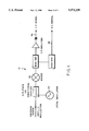
- FIG. 1 is a schematic illustration of the active radiometer of the present invention.
- FIG. 2a is a plan view of a phase splitter for use in conjunction with the invention.
- FIG. 2b is a cross-sectional view of the phase splitter of FIG. 2a.
- FIG. 3 is a cross-sectional view of a surface whose temperature is to be measured.
- FIG. 4 is a block diagram of the millimeter/sub-millimeter receiver used in the invention.
- the present invention is based on using a millimeter/sub-millimeter-wave radiometer to detect the electromagnetic radiation from furnace walls.
- Millimeter-wave radiometers are commonly used for measuring temperature in the environment. See, J. H. Rainwater, "Radiometers: Electronic Eyes that See Noise," Microwaves, pp. 58-62, September 1978. Such radiometers, however, have not been used in the hot, hostile environment present within a furnace.
- the active radiometer system 10 of the invention includes a millimeter/sub-millimeter-wave receiver 12.
- the receiver 12 receives energy through a waveguide taper and transition 14 which serves as an interface between the fundamental waveguide 16 of the receiver and a more efficient overmoded transmission line 18.
- This interface may also be optical, via a lens or focusing mirror if the receiver 12 mixer uses a quasi-optical antenna such as a corner cube.
- a quasi-optical antenna such as a corner cube.
- a smooth walled metal waveguide such as a cylindrical copper tube as shown at 18 is used as the transmission line to propagate a transverse electric (TE) field mode
- a mode converter 20 to convert the TE transmission line mode to an HE 11 mode. See, M. Tumm, "Computer-aided Analysis and Design of Corrugated TE 11 to HE 11 Mode Converters in Highly Overmoded Waveguides," Intern: J. of Infrared and Millimeter Waves, Vol. 6, pp. 577-597, 1985.
- a mode converter such as the mode converter 20 is not necessary if the receiver field-of-view is already in an optical beam such as from a corner cube antenna.
- the HE 11 mode is the most efficient waveguide mode that can be propagated by waveguide and efficiently couples to a free space Gaussian beam.
- a Gaussian beam is the best free space propagating mode for achieving diffraction limited spatial resolution.
- Propagating an HE 11 mode in waveguide requires either a dielectric waveguide or a corrugated internal surface for a waveguide made from a conductor material. It is the properties of the HE 11 mode which forms the basis for the use of a graphite waveguide material inside a furnace 22 and for achieving the best possible spatial resolution.
- the inventors herein have found that graphite is a good conductor in the millimeter/sub-millimeter wavelength range and can be made into an efficient corrugated waveguide for HE 11 mode propagation over short distances.
- a chopper 24 which periodically blocks the receiver 12 field-of-view into the furnace 22 by means of room temperature blades 26.
- the blades 26 are covered with a millimeter/sub-millimeter-wave absorbing material such as EccosorbTM to provide a room temperature black-body reference signal as in a Dicke receiver. See, J. D. Krauss, Radio Astronomy, Chapter 7 by M. E. Tiuri, "Radio-Telescope Receivers," McGraw Hill, New York, 1975.
- the chopper 24 provides reference signals 28 and 30 corresponding to the chopping frequency to lock in amplifiers 32 and 34.
- the lock in amplifier 32 is provided for the detection of the intermediate frequency (IF) signal 36 from the receiver 12 corresponding to surface emission and the lock in amplifier 34 is provided for the detection of the chopper modulated DC signal 38 from the receiver 12 corresponding to surface reflection.
- signal 38 could be an IF signal at a different frequency from IF signal 36 if the probe beam is at a different frequency relative to the local oscillator.
- a signal processor or computer 39 operates on signals from the amplifiers 32 and 34 to produce the temperature measurement. Those skilled in the art will recognize that such a signal processor or computer is well known and widely used for applications such as for the radiometer system of the invention.
- a phase splitter 40 is disposed between the chopper 24 and a window 42 in a graphite waveguide 44.
- the phase splitter 40 will be described in more detail below in conjunction with FIGS. 2a and 2b.
- the window 42 spans the waveguide 44 to seal the furnace 22.
- the window 42 is made of a material that is transparent in the millimeter/sub-millimeter-wave range such as teflon, polyethylene, or quartz. Teflon is the preferred choice at the longer wavelength end of the millimeter/sub-millimeter-wave range because of its low index of refraction which minimizes window surface reflection losses. Window reflection losses can also further be minimized by corrugating the surfaces (See, S. J. Wilson and M. C. Hutley, "The Optical Properties of Moth Eye Antireflection Surfaces," Optica Acta, Vol. 29, pp. 993-1009, 1982) or Brewster's angle placement.
- the corrugated HE 11 graphite waveguide 44 because of the higher resistivity of graphite, is of a larger diameter than the copper transmission line 18 to keep transmission losses low. As will be appreciated by those skilled in the art, transmission line losses are inversely proportional to the third power of the waveguide radius. Another advantage of a larger diameter waveguide at the furnace end is that the divergence of the receiver 12 field-of-view is minimized for good spatial resolution.
- a waveguide taper is used to increase the guide diameter. In FIG. 1, this taper is shown in the graphite waveguide 44 on the furnace side of the window 42 but it could also be made of copper on the outside of the furnace window.
- a graphite mirror 46 is used to direct receiver 12 field-of-view toward the hot furnace surface 48 to be monitored for temperature.
- the graphite waveguide 44 and the mirror 46 may be rotated to scan a temperature profile.
- a further function of the mirror 46 is to block the window 42 from having a direct view of the hot surface 48 which keeps the window 42 cleaner and cooler. Deposits, however, on the window 42 or mirror 46 are not critical because of the millimeter/submillimeter wavelength of operation.
- the receiver 12 includes a local oscillator or other source for a probe beam.
- the purpose of the phase splitter 40 is to compensate for the coherent nature of the probe beam. Instrumental standing wave interference effects are averaged out with the phase splitter 40.
- the phase splitter 40 is positioned so that the step precisely cuts through the middle of the radiometer beam so that half the beam goes through the thicker part and the other half goes through the thinner part.
- the two halves of the beam are 180° out of phase with each other. If the top half of the beam is on an interference peak, the bottom half will be on an interference minimum, and conversely. Therefore the coherent interference in the local oscillator beam is always automatically averaged out. More than one step can be used to reduce the requirement for precise positioning of the phase splitter.
- the hot surface 48 whose temperature is to be measured is preferably made up of 90° corners or retroreflectors in a refractory material such as bricks 49 used for lining the wall of the furnace 22.
- An orientation angle represented by ⁇ can be skewed so that the comers are machined in a direction from which the radiometer beam 50 is coming.
- the 90° corners shown in FIG. 3 do not have to be three-dimensional if the radiometer beam 50 is in the same plane as the corners.
- the reflectivity of a flat sample of brick material 49 is first calibrated at room temperature; then this value is used to calibrate the room temperature reflectivity of the corner reflector.
- the corner reflection signal is generally equal to the flat surface reflectivity squared.
- Alternative retroreflector designs can include focusing mirror surfaces machined into refractory material.
- the step of phasesplitter 40 would be oriented orthogonal to the valley of corners 48.
- the receiver 12 has two outputs, namely the IF signal 36 and the DC signal 38.
- the two outputs 36 and 38 correspond to the intermediate frequency signal and to the direct current level on a mixer 52.
- the IF signal 36 has a wide bandwidth (approximately 1-10 GHz) double sideband and is the down shifted emission frequency from the hot surface 48 being monitored. This signal 36 is linearly proportional to the temperature of the surface 48. Wide bandwidth operation is important for good signal-to-noise ratio since the signal-to-noise ratio is proportional to the square root of the bandwidth.
- the DC signal 38 has a component that is proportional to the reflection from the hot surface 48 of a local oscillator (LO) 54 beam 55 (FIG. 1 ).
- the DC signal 38 is modulated by the chopper 24 and therefore is readily distinguishable from the LO and DC bias levels on the mixer 52.
- the present invention takes advantage of the back reflection of a part of the local oscillator 54 signal 55 incident on the mixer 52 back along the receiver field-of-view after reflection from the hot surface 48.
- a source different from the local oscillator could be used for the probe beam.
- signal 38 would be an IF signal with the surface reflection signal and signal 36 would be the IF signal without the surface reflection signal.
- the reflectivity of the hot surface is related to its emissivity through Kirchhoff's law. See, F. P. Incropera and D. P. DeWitt, Introduction to Heat Transfer, 2nd Ed. , Chapter 12, Section 12.6, John Wiley and Sons, New York, 1990.
- the emissivity of a surface must be known in order to interpret the surface emission, as measured by the surface emission IF signal, as a temperature.
- the present invention provides for simultaneous surface emissivity calibration.
- an alternative scheme frequency modulates the local oscillator.
- the frequency sweep of the modulation should be as great as or greater than where c is the speed of light and L is the path length from the receiver 12 to the hot surface 48 which is being observed. Such a frequency sweep should be made rapidly compared to signal integration time.
- the received signal will then be an average of the instrumental interference peaks and minima.
- This alternative scheme for compensation for local oscillator 54 coherence is averaging in the time domain whereas the phase splitter 40 effects averaging in the spatial domain. A combination of both of these coherence compensation schemes may be used.
- energy 57 from the hot surface 48 is directed into the graphite waveguide 44.
- This energy 57 is a combination of energy emitted from the hot surface 48 and portion 55 of the local oscillator 54 energy reflected from the hot surface 48.
- This combined emission and reflection energy 57 passes through the window 42 and phase splitter 40 and is chopped by the chopper 24.
- the energy proceeds through the mode converter 20 into the waveguide 18 and subsequently through the fundamental waveguide 16 to the receiver 12.
- the receiver 12 has an IF output 36 and a DC output 38.
- the IF signal 36 is linearly proportional to the temperature of the surface and the DC signal 38 is proportional to the reflectivity of the hot surface 48.
- the reflectivity is related to its emissivity through Kirchhoff's law.
- the IF signal 36 and the DC signal 38 are processed in the signal processor 39 to generate the temperature measurement.
- the active radiometer of the invention is being continuously calibrated for any changes in emissivity which result from surface deposits or other factors.
- the present invention provides reliable, robust temperature measurement instrumentation for the monitoring, control and development of furnaces. It is recognized that modifications and variations of the invention disclosed herein will occur to those skilled in the art and it is intended that all such modifications and variations be included within the scope of the appended claims.
Abstract
Description
Claims (11)
Priority Applications (6)
| Application Number | Priority Date | Filing Date | Title |
|---|---|---|---|
| US08/181,706 US5573339A (en) | 1994-01-14 | 1994-01-14 | Active radiometer for self-calibrated furnace temperature measurements |
| PCT/US1995/000404 WO1995019575A1 (en) | 1994-01-14 | 1995-01-12 | Active radiometer for self-calibrated furnace temperature measurements |
| EP95907398A EP0689678A1 (en) | 1994-01-14 | 1995-01-12 | Active radiometer for self-calibrated furnace temperature measurements |
| JP7519104A JPH08511107A (en) | 1994-01-14 | 1995-01-12 | Active radiometer for self-calibrating furnace temperature measurement |
| CA002158146A CA2158146A1 (en) | 1994-01-14 | 1995-01-12 | Active radiometer for self-calibrated furnace temperature measurements |
| US08/539,818 US5785426A (en) | 1994-01-14 | 1995-10-06 | Self-calibrated active pyrometer for furnace temperature measurements |
Applications Claiming Priority (1)
| Application Number | Priority Date | Filing Date | Title |
|---|---|---|---|
| US08/181,706 US5573339A (en) | 1994-01-14 | 1994-01-14 | Active radiometer for self-calibrated furnace temperature measurements |
Related Child Applications (1)
| Application Number | Title | Priority Date | Filing Date |
|---|---|---|---|
| US08/539,818 Continuation-In-Part US5785426A (en) | 1994-01-14 | 1995-10-06 | Self-calibrated active pyrometer for furnace temperature measurements |
Publications (1)
| Publication Number | Publication Date |
|---|---|
| US5573339A true US5573339A (en) | 1996-11-12 |
Family
ID=22665439
Family Applications (1)
| Application Number | Title | Priority Date | Filing Date |
|---|---|---|---|
| US08/181,706 Expired - Fee Related US5573339A (en) | 1994-01-14 | 1994-01-14 | Active radiometer for self-calibrated furnace temperature measurements |
Country Status (5)
| Country | Link |
|---|---|
| US (1) | US5573339A (en) |
| EP (1) | EP0689678A1 (en) |
| JP (1) | JPH08511107A (en) |
| CA (1) | CA2158146A1 (en) |
| WO (1) | WO1995019575A1 (en) |
Cited By (14)
| Publication number | Priority date | Publication date | Assignee | Title |
|---|---|---|---|---|
| US5785426A (en) * | 1994-01-14 | 1998-07-28 | Massachusetts Institute Of Technology | Self-calibrated active pyrometer for furnace temperature measurements |
| WO1998041826A1 (en) * | 1997-01-27 | 1998-09-24 | Regents Of The University Of California | Single-fiber multi-color pyrometry |
| WO2001053434A1 (en) | 2000-01-21 | 2001-07-26 | Integrated Environmental Technologies, Llc. | Methods and apparatus for treating waste |
| US6352192B1 (en) * | 2000-02-29 | 2002-03-05 | Motorola, Inc. | System and method to control solder reflow furnace with wafer surface characterization |
| US6682216B1 (en) * | 1999-12-16 | 2004-01-27 | The Regents Of The University Of California | Single-fiber multi-color pyrometry |
| US7059765B2 (en) * | 2000-03-10 | 2006-06-13 | The University Court Of The University Of Glasgow | Temperature measuring apparatus and related improvements |
| US20080290265A1 (en) * | 2007-05-21 | 2008-11-27 | Robert Patrick Daly | System and method of calibrating a millimeter wave radiometer using an optical chopper |
| US20090286346A1 (en) * | 2008-05-14 | 2009-11-19 | International Business Machines Corporation | Methods For Forming Anti-Reflection Structures For CMOS Image Sensors |
| US20090283807A1 (en) * | 2008-05-14 | 2009-11-19 | International Business Machines Corporation | Anti-Reflection Structures For CMOS Image Sensors |
| US20100008395A1 (en) * | 2008-07-11 | 2010-01-14 | Daniel William E | Milliwave melter monitoring system |
| US20140035779A1 (en) * | 2012-07-31 | 2014-02-06 | Radiometrics Corporation | Highly accurate calibration of microwave radiometry devices |
| US10876898B2 (en) | 2018-08-08 | 2020-12-29 | National Technology & Engineering Solutions Of Sandia, Llc | Passive millimeter wave radiometer system for calibration of infrared cameras |
| CN112729605A (en) * | 2021-02-26 | 2021-04-30 | 王世有 | Optical fiber temperature measurement system based on spectrum absorption principle |
| US11187587B1 (en) * | 2020-08-12 | 2021-11-30 | Rohde & Schwarz Gmbh & Co. Kg | Calibration device and method of calibrating a microwave radiometer |
Families Citing this family (1)
| Publication number | Priority date | Publication date | Assignee | Title |
|---|---|---|---|---|
| ATE376879T1 (en) * | 2003-04-01 | 2007-11-15 | Shell Int Research | OLEFIN EPOXIDATION PROCESS AND CATALYST FOR USE IN THE PROCESS |
Citations (19)
| Publication number | Priority date | Publication date | Assignee | Title |
|---|---|---|---|---|
| GB1436180A (en) * | 1972-07-27 | 1976-05-19 | Bbc Brown Boveri & Cie | Process for contactless and material independent temperature measurement on surface |
| US4235107A (en) * | 1978-01-27 | 1980-11-25 | U.S. Philips Corporation | Method and arrangement for measuring the physical temperature of an object by means of microwaves |
| JPS56109844A (en) * | 1980-01-31 | 1981-08-31 | Daiichi Kasei Kk | Surface treatment of glass fiber |
| US4292638A (en) * | 1971-06-17 | 1981-09-29 | Sperry Corporation | Augmented radiometric system |
| JPS57161521A (en) * | 1981-03-31 | 1982-10-05 | Chino Works Ltd | Radiation thermometer |
| JPS58171643A (en) * | 1982-04-01 | 1983-10-08 | Nippon Steel Corp | Method and apparatus for measuring temperature of tube-like substance |
| US4568199A (en) * | 1983-04-06 | 1986-02-04 | Shell Oil Company | Microwave pyrometer |
| US4708493A (en) * | 1986-05-19 | 1987-11-24 | Quantum Logic Corporation | Apparatus for remote measurement of temperatures |
| US4919542A (en) * | 1988-04-27 | 1990-04-24 | Ag Processing Technologies, Inc. | Emissivity correction apparatus and method |
| US4956538A (en) * | 1988-09-09 | 1990-09-11 | Texas Instruments, Incorporated | Method and apparatus for real-time wafer temperature measurement using infrared pyrometry in advanced lamp-heated rapid thermal processors |
| US4979134A (en) * | 1988-07-15 | 1990-12-18 | Minolta Camera Kabushiki Kaisha | Method for measuring surface temperature of semiconductor wafer substrate, and heat-treating apparatus |
| US4979133A (en) * | 1988-02-08 | 1990-12-18 | Minolta Camera Kabushiki Kaisha | Pyrometer |
| US4984902A (en) * | 1989-04-13 | 1991-01-15 | Peak Systems, Inc. | Apparatus and method for compensating for errors in temperature measurement of semiconductor wafers during rapid thermal processing |
| US5029117A (en) * | 1989-04-24 | 1991-07-02 | Tektronix, Inc. | Method and apparatus for active pyrometry |
| US5036289A (en) * | 1989-03-17 | 1991-07-30 | Infrared Systems, Inc. | Method and apparatus for synchronously demodulating detector output of a radiometer |
| US5255286A (en) * | 1991-05-17 | 1993-10-19 | Texas Instruments Incorporated | Multi-point pyrometry with real-time surface emissivity compensation |
| US5305416A (en) * | 1993-04-02 | 1994-04-19 | At&T Bell Laboratories | Semiconductor processing technique, including pyrometric measurement of radiantly heated bodies |
| US5308161A (en) * | 1993-02-11 | 1994-05-03 | Quantum Logic Corporation | Pyrometer apparatus for use in rapid thermal processing of semiconductor wafers |
| US5326173A (en) * | 1993-01-11 | 1994-07-05 | Alcan International Limited | Apparatus and method for remote temperature measurement |
Family Cites Families (1)
| Publication number | Priority date | Publication date | Assignee | Title |
|---|---|---|---|---|
| JPS56108944A (en) * | 1980-02-01 | 1981-08-28 | Mitsubishi Electric Corp | Microwave radiometer |
-
1994
- 1994-01-14 US US08/181,706 patent/US5573339A/en not_active Expired - Fee Related
-
1995
- 1995-01-12 WO PCT/US1995/000404 patent/WO1995019575A1/en not_active Application Discontinuation
- 1995-01-12 JP JP7519104A patent/JPH08511107A/en active Pending
- 1995-01-12 CA CA002158146A patent/CA2158146A1/en not_active Abandoned
- 1995-01-12 EP EP95907398A patent/EP0689678A1/en not_active Withdrawn
Patent Citations (19)
| Publication number | Priority date | Publication date | Assignee | Title |
|---|---|---|---|---|
| US4292638A (en) * | 1971-06-17 | 1981-09-29 | Sperry Corporation | Augmented radiometric system |
| GB1436180A (en) * | 1972-07-27 | 1976-05-19 | Bbc Brown Boveri & Cie | Process for contactless and material independent temperature measurement on surface |
| US4235107A (en) * | 1978-01-27 | 1980-11-25 | U.S. Philips Corporation | Method and arrangement for measuring the physical temperature of an object by means of microwaves |
| JPS56109844A (en) * | 1980-01-31 | 1981-08-31 | Daiichi Kasei Kk | Surface treatment of glass fiber |
| JPS57161521A (en) * | 1981-03-31 | 1982-10-05 | Chino Works Ltd | Radiation thermometer |
| JPS58171643A (en) * | 1982-04-01 | 1983-10-08 | Nippon Steel Corp | Method and apparatus for measuring temperature of tube-like substance |
| US4568199A (en) * | 1983-04-06 | 1986-02-04 | Shell Oil Company | Microwave pyrometer |
| US4708493A (en) * | 1986-05-19 | 1987-11-24 | Quantum Logic Corporation | Apparatus for remote measurement of temperatures |
| US4979133A (en) * | 1988-02-08 | 1990-12-18 | Minolta Camera Kabushiki Kaisha | Pyrometer |
| US4919542A (en) * | 1988-04-27 | 1990-04-24 | Ag Processing Technologies, Inc. | Emissivity correction apparatus and method |
| US4979134A (en) * | 1988-07-15 | 1990-12-18 | Minolta Camera Kabushiki Kaisha | Method for measuring surface temperature of semiconductor wafer substrate, and heat-treating apparatus |
| US4956538A (en) * | 1988-09-09 | 1990-09-11 | Texas Instruments, Incorporated | Method and apparatus for real-time wafer temperature measurement using infrared pyrometry in advanced lamp-heated rapid thermal processors |
| US5036289A (en) * | 1989-03-17 | 1991-07-30 | Infrared Systems, Inc. | Method and apparatus for synchronously demodulating detector output of a radiometer |
| US4984902A (en) * | 1989-04-13 | 1991-01-15 | Peak Systems, Inc. | Apparatus and method for compensating for errors in temperature measurement of semiconductor wafers during rapid thermal processing |
| US5029117A (en) * | 1989-04-24 | 1991-07-02 | Tektronix, Inc. | Method and apparatus for active pyrometry |
| US5255286A (en) * | 1991-05-17 | 1993-10-19 | Texas Instruments Incorporated | Multi-point pyrometry with real-time surface emissivity compensation |
| US5326173A (en) * | 1993-01-11 | 1994-07-05 | Alcan International Limited | Apparatus and method for remote temperature measurement |
| US5308161A (en) * | 1993-02-11 | 1994-05-03 | Quantum Logic Corporation | Pyrometer apparatus for use in rapid thermal processing of semiconductor wafers |
| US5305416A (en) * | 1993-04-02 | 1994-04-19 | At&T Bell Laboratories | Semiconductor processing technique, including pyrometric measurement of radiantly heated bodies |
Non-Patent Citations (14)
| Title |
|---|
| F. P. Incropera and D. P. DeWitt, "Introduction to Heat Transfer", 2nd Ed., Chapter 12, Section 12.6, John Wiley and Sons, New York, 1990. |
| F. P. Incropera and D. P. DeWitt, Introduction to Heat Transfer , 2nd Ed., Chapter 12, Section 12.6, John Wiley and Sons, New York, 1990. * |
| H. R. Fetterman et al., "Far-ir Heterodyne Radiometric Measurements With Quasioptical Schottky Diode Mixers", Appl. Phys. Lett., vol. 33, pp. 151-154, 1978. |
| H. R. Fetterman et al., Far ir Heterodyne Radiometric Measurements With Quasioptical Schottky Diode Mixers , Appl. Phys. Lett., vol. 33, pp. 151 154, 1978. * |
| J. D. Kraus, "Radio Astronomy", Chapter 7 by M. E. Tiuri, Radio-Telescope Receivers, McGraw Hill, New York, 1975. |
| J. D. Kraus, Radio Astronomy , Chapter 7 by M. E. Tiuri, Radio Telescope Receivers, McGraw Hill, New York, 1975. * |
| J. H. Rainwater, "Radiometers: Electronic Eyes that `See` Noise", Microwaves, pp. 58-62, Sep. 1978. |
| J. H. Rainwater, Radiometers: Electronic Eyes that See Noise , Microwaves, pp. 58 62, Sep. 1978. * |
| M. Tumm, "Computer-aided Analysis and Design of Corrugated TE11 to HE11 Mode Converters In Highly Overmoded Waveguides", Intern. J. of Infrared and Millimeter Waves, vol. 6, pp. 577-597, 1985. |
| M. Tumm, Computer aided Analysis and Design of Corrugated TE 11 to HE 11 Mode Converters In Highly Overmoded Waveguides , Intern. J. of Infrared and Millimeter Waves, vol. 6, pp. 577 597, 1985. * |
| Ma et al. "Night Moth Eye Window for the Millimetre and Sub-Millimetre Wave Region" Optica Acta, 30(12), 1685-1695 (1983). |
| Ma et al. Night Moth Eye Window for the Millimetre and Sub Millimetre Wave Region Optica Acta , 30(12), 1685 1695 (1983). * |
| Richard et al., "Mesure de temperature par radiometric hertzienne", Measures Regulation Automatisme, vol. 9, p. 85-94 (Sep. 1964). |
| Richard et al., Mesure de temp e rature par radiometric hertzienne , Measures Regulation Automatisme, vol. 9, p. 85 94 (Sep. 1964). * |
Cited By (24)
| Publication number | Priority date | Publication date | Assignee | Title |
|---|---|---|---|---|
| US5785426A (en) * | 1994-01-14 | 1998-07-28 | Massachusetts Institute Of Technology | Self-calibrated active pyrometer for furnace temperature measurements |
| WO1998041826A1 (en) * | 1997-01-27 | 1998-09-24 | Regents Of The University Of California | Single-fiber multi-color pyrometry |
| US6012840A (en) * | 1997-01-27 | 2000-01-11 | The Regents Of The University Of California | Single-fiber multi-color pyrometry |
| US6682216B1 (en) * | 1999-12-16 | 2004-01-27 | The Regents Of The University Of California | Single-fiber multi-color pyrometry |
| WO2001053434A1 (en) | 2000-01-21 | 2001-07-26 | Integrated Environmental Technologies, Llc. | Methods and apparatus for treating waste |
| US6352192B1 (en) * | 2000-02-29 | 2002-03-05 | Motorola, Inc. | System and method to control solder reflow furnace with wafer surface characterization |
| US7059765B2 (en) * | 2000-03-10 | 2006-06-13 | The University Court Of The University Of Glasgow | Temperature measuring apparatus and related improvements |
| US20080290265A1 (en) * | 2007-05-21 | 2008-11-27 | Robert Patrick Daly | System and method of calibrating a millimeter wave radiometer using an optical chopper |
| US20100264473A1 (en) * | 2008-05-14 | 2010-10-21 | International Business Machines Corporation | Anti-reflection structures for cmos image sensors |
| US8138534B2 (en) | 2008-05-14 | 2012-03-20 | International Business Machines Corporation | Anti-reflection structures for CMOS image sensors |
| US8742560B2 (en) | 2008-05-14 | 2014-06-03 | International Business Machines Corporation | Anti-reflection structures for CMOS image sensors |
| US7759755B2 (en) | 2008-05-14 | 2010-07-20 | International Business Machines Corporation | Anti-reflection structures for CMOS image sensors |
| US20090286346A1 (en) * | 2008-05-14 | 2009-11-19 | International Business Machines Corporation | Methods For Forming Anti-Reflection Structures For CMOS Image Sensors |
| US8716771B2 (en) | 2008-05-14 | 2014-05-06 | International Business Machines Corporation | Anti-reflection structures for CMOS image sensors |
| US8003425B2 (en) | 2008-05-14 | 2011-08-23 | International Business Machines Corporation | Methods for forming anti-reflection structures for CMOS image sensors |
| US20090283807A1 (en) * | 2008-05-14 | 2009-11-19 | International Business Machines Corporation | Anti-Reflection Structures For CMOS Image Sensors |
| US8409904B2 (en) | 2008-05-14 | 2013-04-02 | International Business Machines Corporation | Methods for forming anti-reflection structures for CMOS image sensors |
| US7997121B2 (en) | 2008-07-11 | 2011-08-16 | Savannah River Nuclear Solutions, Llc | Milliwave melter monitoring system |
| US20100008395A1 (en) * | 2008-07-11 | 2010-01-14 | Daniel William E | Milliwave melter monitoring system |
| US20140035779A1 (en) * | 2012-07-31 | 2014-02-06 | Radiometrics Corporation | Highly accurate calibration of microwave radiometry devices |
| US10876898B2 (en) | 2018-08-08 | 2020-12-29 | National Technology & Engineering Solutions Of Sandia, Llc | Passive millimeter wave radiometer system for calibration of infrared cameras |
| US11187587B1 (en) * | 2020-08-12 | 2021-11-30 | Rohde & Schwarz Gmbh & Co. Kg | Calibration device and method of calibrating a microwave radiometer |
| CN114112072A (en) * | 2020-08-12 | 2022-03-01 | 罗德施瓦兹两合股份有限公司 | Calibration device and method for calibrating microwave radiometer |
| CN112729605A (en) * | 2021-02-26 | 2021-04-30 | 王世有 | Optical fiber temperature measurement system based on spectrum absorption principle |
Also Published As
| Publication number | Publication date |
|---|---|
| WO1995019575A1 (en) | 1995-07-20 |
| CA2158146A1 (en) | 1995-07-20 |
| JPH08511107A (en) | 1996-11-19 |
| EP0689678A1 (en) | 1996-01-03 |
Similar Documents
| Publication | Publication Date | Title |
|---|---|---|
| US5785426A (en) | Self-calibrated active pyrometer for furnace temperature measurements | |
| US5573339A (en) | Active radiometer for self-calibrated furnace temperature measurements | |
| WO1997013128A9 (en) | Active pyrometer for self-calibrated furnace temperature measurements | |
| Määttä et al. | Profiling of hot surfaces by pulsed time-of-flight laser range finder techniques | |
| Woskov et al. | Corrugated waveguide and directional coupler for CW 250-GHz gyrotron DNP experiments | |
| Chen et al. | Terahertz electrometry via infrared spectroscopy of atomic vapor | |
| US11906368B2 (en) | Temperature measurement system and method using optical signal transmission through an optical interferometer | |
| Hanson et al. | ATF two‐frequency correlation reflectometer | |
| JP2008064653A (en) | Spectrometer | |
| JPH0259414B2 (en) | ||
| Woskov et al. | Thermal return reflection method for resolving emissivity and temperature in radiometric measurements | |
| CN112558001B (en) | Pulse high-power field calibration device and method | |
| Samson | Analysis of the wavelength dependence of Raman backscatter in optical fibre thermometry | |
| Woskov et al. | Active millimeter‐wave pyrometer | |
| Lengyel | A Michelson-type interferometer for microwave measurements | |
| Pyrometer et al. | “Pacific Northwest Laboratories, Richland, WA 99352 | |
| US10876898B2 (en) | Passive millimeter wave radiometer system for calibration of infrared cameras | |
| Zaitsev et al. | A calorimeter for measuring the energy of high-power electromagnetic pulses | |
| Malygin et al. | Determination of the mode content in spurious microwave radiation of the gyrotron with a straight axisymmetric output | |
| Harvey | Instruments for use in the microwave band | |
| Austin et al. | Conceptual Design of the ITER ECE Diagnostic–An Update | |
| Fellers | Measurements in the millimeter to micron range | |
| IT1228039B (en) | SENSOR AND EQUIPMENT FOR MEASURING RADIANT ENERGY, IN PARTICULAR THE ENERGY ASSOCIATED WITH RADIOFREQUENCY SIGNALS, MICROWAVES AND LIGHT RADIATIONS | |
| Sasao et al. | ECE diagnostics in the high density plasma in LHD | |
| Vorobjov et al. | A device for experimental research on wave electromagnetic processes in multiply connected quasi-optical systems with periodic inhomogeneities |
Legal Events
| Date | Code | Title | Description |
|---|---|---|---|
| AS | Assignment |
Owner name: MASSACHUSETTS INSTITUTE OF TECHNOLOGY, MASSACHUSET Free format text: ASSIGNMENT OF ASSIGNORS INTEREST;ASSIGNORS:WOSKOV, PAUL P.;COHN, DANIEL R.;H. TITUS, CHARLES;AND OTHERS;REEL/FRAME:007184/0600;SIGNING DATES FROM 19940330 TO 19940510 |
|
| AS | Assignment |
Owner name: BATTELLE MEMORIAL INSTITUTE, WASHINGTON Free format text: ASSIGNMENT OF ASSIGNORS INTEREST;ASSIGNOR:SURMA, JEFFREY E.;REEL/FRAME:007637/0375 Effective date: 19950426 |
|
| AS | Assignment |
Owner name: ELECTRO-PYROLYSIS, INCORPORATED, PENNSYLVANIA Free format text: ASSIGNMENT OF ASSIGNORS INTEREST;ASSIGNOR:WITTLE, J. KENNETH;REEL/FRAME:007874/0606 Effective date: 19960318 |
|
| CC | Certificate of correction | ||
| FEPP | Fee payment procedure |
Free format text: PAYOR NUMBER ASSIGNED (ORIGINAL EVENT CODE: ASPN); ENTITY STATUS OF PATENT OWNER: SMALL ENTITY |
|
| FPAY | Fee payment |
Year of fee payment: 4 |
|
| SULP | Surcharge for late payment | ||
| REMI | Maintenance fee reminder mailed | ||
| FPAY | Fee payment |
Year of fee payment: 8 |
|
| SULP | Surcharge for late payment |
Year of fee payment: 7 |
|
| REMI | Maintenance fee reminder mailed | ||
| LAPS | Lapse for failure to pay maintenance fees | ||
| STCH | Information on status: patent discontinuation |
Free format text: PATENT EXPIRED DUE TO NONPAYMENT OF MAINTENANCE FEES UNDER 37 CFR 1.362 |
|
| FP | Lapsed due to failure to pay maintenance fee |
Effective date: 20081112 |