US5572592A - Remote control audio apparatus for hunters - Google Patents

Remote control audio apparatus for hunters Download PDF

Info

Publication number
US5572592A
US5572592A US08/452,885 US45288595A US5572592A US 5572592 A US5572592 A US 5572592A US 45288595 A US45288595 A US 45288595A US 5572592 A US5572592 A US 5572592A
Authority
US
United States
Prior art keywords
remote control
radio
audio
speaker
receiver
Prior art date
Legal status (The legal status is an assumption and is not a legal conclusion. Google has not performed a legal analysis and makes no representation as to the accuracy of the status listed.)
Expired - Fee Related
Application number
US08/452,885
Inventor
Bruce Muckelrath
Current Assignee (The listed assignees may be inaccurate. Google has not performed a legal analysis and makes no representation or warranty as to the accuracy of the list.)
R & L RESEARCH LLC
Original Assignee
Muckelrath; Bruce
Priority date (The priority date is an assumption and is not a legal conclusion. Google has not performed a legal analysis and makes no representation as to the accuracy of the date listed.)
Filing date
Publication date
US case filed in California Central District Court litigation Critical https://portal.unifiedpatents.com/litigation/California%20Central%20District%20Court/case/8%3A07-cv-01199 Source: District Court Jurisdiction: California Central District Court "Unified Patents Litigation Data" by Unified Patents is licensed under a Creative Commons Attribution 4.0 International License.
Application filed by Muckelrath; Bruce filed Critical Muckelrath; Bruce
Priority to US08/452,885 priority Critical patent/US5572592A/en
Application granted granted Critical
Publication of US5572592A publication Critical patent/US5572592A/en
Assigned to R & L RESEARCH , LLC reassignment R & L RESEARCH , LLC ASSIGNMENT OF ASSIGNORS INTEREST (SEE DOCUMENT FOR DETAILS). Assignors: CASTAGNO, JOE, MUCKELRATH, BRUCE
Assigned to CASTAGNO, JOE reassignment CASTAGNO, JOE ASSIGNMENT OF ASSIGNORS INTEREST (SEE DOCUMENT FOR DETAILS). Assignors: MUCKELRATH, BRUCE
Anticipated expiration legal-status Critical
Expired - Fee Related legal-status Critical Current

Links

Images

Classifications

    • HELECTRICITY
    • H04ELECTRIC COMMUNICATION TECHNIQUE
    • H04RLOUDSPEAKERS, MICROPHONES, GRAMOPHONE PICK-UPS OR LIKE ACOUSTIC ELECTROMECHANICAL TRANSDUCERS; DEAF-AID SETS; PUBLIC ADDRESS SYSTEMS
    • H04R27/00Public address systems

Definitions

  • the present invention relates to an audio apparatus for use by hunters and, in particular, for an audio apparatus having the capability of either recording or reproducing predator calls, game calls and the like.
  • the present invention further relates to an audio apparatus for use by hunters which may be operated by radio remote control using a detachable radio receiver mounted to the audio apparatus.
  • a more sophisticated type of game call employs the same type of mechanical apparatus but introduces the additional feature of remote control. This allows the hunter to be stationed some distance from the source of the sound so as to reduce the potential for warning the animal away by the near presence of the hunter.
  • An example of a remote control decoy is found in U.S. Pat. No. 4,965,953 issued to McKinney on Oct. 30, 1990 for "Remote Controlled Turkey Decoy.” McKinney discloses a wild turkey decoy having a control line attached to head and neck members whereby a pull on the control line causes the decoy to simulate the motions of a feeding bird.
  • McKinney discloses remote control of a decoy apparatus, it does not disclose remotely controlling production of the sound of the game animal.
  • a remote control game calling device is disclosed in U.S. Pat. No. 4,862,625 issued to Dolan on Sep. 5, 1989 for "Remotely Controlled Turkey Calling Device.”
  • Dolan discloses a trigger device which provides for a push-pull motion of a cable which activates a remotely located game calling device.
  • Dolan is strictly a mechanical device relying on direct connection between the operator controlled trigger mechanism and the mechanical sound reproduction apparatus.
  • Overholt discloses a turkey decoy having a mechanical type turkey call.
  • the turkey call and the motion of the decoy are remotely controlled using a radio transmitter mechanically operated by the hunter which transmits radio signals to a receiver on the decoy to operate both the game call and the motion of the decoy.
  • radio remote control so that the hunter may operate the apparatus from a distance so as not to disturb the predator or game animals by the near presence of the hunter. It is desirable to provide for a detachable radio receiver controlling the capabilities of the audio apparatus.
  • a detachable radio receiver allows the option of manual operation of the audio apparatus.
  • a detachable radio receiver may be employed on more than one device with the attendant savings in costs and with greater flexibility.
  • Detachable radio remote control receivers have been employed in unrelated arts but the inventor is unaware of the use of detachable radio remote control receivers on an audio apparatus adapted for use by hunters.
  • U.S. Pat. No. 4,549,179 issued to Stendardo on Oct. 22, 1985 discloses a radio remote control unit for use on home electronic equipment possessing an audio output.
  • Stendardo's radio remote control receiver unit includes its own speaker which replaces the disabled internal speaker of the equipment to be controlled.
  • a hand-held remote control transmitter is used to control the volume of the speaker in the remote control receiver unit.
  • an audio apparatus having means for recording and/or reproducing predator calls, game calls and the like is disposed within a weather resistant case so that the apparatus may be deployed by a hunter for either recording the sound of animals in their natural environment or for reproducing predator calls, game calls and the like. Both recording and reproduction capabilities may be present in a given embodiment of the present invention or only recording or reproduction may be required in a particular application.
  • the present invention further provides for remote control of the audio apparatus through a remote radio transmitter operated by the hunter and communicating with a radio receiver to control the operation of the audio apparatus.
  • the present invention further provides for detachability of the radio remote control receiver.
  • FIG. 1 is a perspective view of the present invention as deployed for operation with the detachable radio remote control receiver in position and the external speaker disposed on the exterior surface of the weather resistant enclosure.
  • FIG. 2 is a perspective view of the present invention with the weather resistant enclosure open to show the radio transmitter, detachable remote control receiver and external speaker in the stored position.
  • FIG. 3 is an electrical schematic of the TX-66 radio receiver.
  • FIG. 4 is an electrical schematic of the interface circuitry for the TX-66 radio transmitter.
  • FIG. 5 is an electrical schematic of the circuitry of the RE-66 radio receiver.
  • FIGS. 6 is electrical schematics of the interface circuitry for the RE-66 receiver.
  • FIGS. 7 is electrical schematics of the control circuitry.
  • FIG. 8 is a block diagram of the interconnections among the electrical components.
  • a weather resistant case 10 is provided to house a cassette recorder 11 which provides either recording or playback of audio information.
  • the weather resistant case 10 includes a bottom section 12 and a lid 13.
  • the bottom section 12 and the lid 13 are each of molded one piece construction so as to present a continuous barrier to moisture infiltration into the interior of the case 10.
  • a seal 14 between the bottom section 12 and the lid 13 provide for additional security against the entry of moisture and thus render the entire case 10 weather resistant when closed as shown in FIG. 1.
  • the lid 13 is latched closed by means of latches 15 and since it is intended to be portable, it is provided with a handle 16.
  • a pressure relief valve 17 may be actuated to allow air into the interior of the case 10 so as to allow for opening of the lid 13.
  • FIG. 2 shows the radio transmitter 20 and the detachable radio receiver 21 stowed within the lid 13.
  • the radio transmitter 20 and the radio receiver 21 may be attached to the lid 13 by means of hook and loop type fasteners of the velcro type or similar means.
  • the radio receiver 21 is provided with an antenna 22. Sufficient space is provided within the lid 13 for stowing the antenna 22 with a minimal degree of bending.
  • the case 10 further provides storage space in the bottom section 12 for the external speaker 23.
  • the external speaker 23 may be attached to the bottom section 12 using velcro type fasteners as described above with reference to the radio transmitter 20 and radio receiver 21.
  • the preferred fastener is the dual-lock material manufactured by 3M.
  • the dual-lock material is also preferred for attaching the external speaker 23 to the exterior of the case 10 as shown on FIG. 1.
  • a dual-lock pad 24 is affixed to the top surface 25 of the lid 13.
  • a complementary portion of dual-lock material is fastened to the base 26 of the external speaker 23.
  • the external speaker 23 is thus removably attached to the exterior of the case 10 and may be removed for storage as shown in FIG. 2.
  • FIG. 1 shows the present invention as deployed for use.
  • the external speaker 23 is attached to the top surface 25 of the lid 13.
  • the lid 13 is firmly closed so as to render the interior of the case 10 weather tight thereby protecting the cassette recorder 11 and additional circuitry located within the case 10 as will be described more completely hereafter.
  • a 4-pin electrical connector 28 is disposed with a screw-on, waterproof cap 29.
  • the 4-pin connector 28 is electrically connected to the circuitry in the interior of the case 10 and provides a point of connection for the speaker plug 30 which is electrically connected via a cable 31 to the external speaker 23.
  • an 8-pin connector 32 having a screw-on, waterproof cap 33.
  • the 8-pin connector 32 is electrically connected to the circuitry in the interior of the case 10 and provides a point of connection for the detachable radio remote control receiver 21.
  • the exterior 27 of the bottom portion 12 also contains a volume control knob 34 which is electrically connected to the circuitry located in the interior of the case 10 for manual control when the radio remote control receiver 21 is not in use.
  • the latches 15 are released and the lid 13 raised to provide access to the interior of the case 10.
  • the external speaker 23 is removed from the interior of the case 10 and by means of the dual-lock connectors disposed on the exterior surface 25 of the lid 13.
  • the screw-on cap 29 of the 4-pin connector 28 is removed and the speaker plug 30 is plugged into the 4-pin connector 28.
  • the screw-on cap 33 of the 8-pin connector 32 is removed.
  • the detachable radio remote control receiver 21 is removed from the lid 13 and plugged into the 8-pin connector 32 by means of an 8-pin plug 35 which is electrically connected to the circuitry of the radio remote control receiver 21 as will be described more completely hereafter.
  • the radio remote control transmitter is removed and retained by the user.
  • the lid 13 is then placed in position against the seal 14 and the latch is operated to provide a complete weather resistant enclosure.
  • the apparatus may then be placed in position by the hunter as appropriate.
  • the hunter then retires to a distance from the apparatus.
  • the hunter may then manually operate the radio remote control transmitter 20 so as to send signals to the remote control receiver 21.
  • the remote control receiver 21 then transmits electrical signals to the interior circuitry of the case 10 in a manner that will be more completely described hereinafter so as to operate the cassette recorder 11.
  • the output of the cassette recorder 11 is electrically connected to the external speaker 23 for reproduction of those sounds that have been recorded on the cassette recorder.
  • the cassette recorder 11 may contain a tape having selected predator calls, game calls or the like.
  • the radio remote control transmitter 20 may be used to turn the cassette recorder on and off and to adjust volume up and down.
  • the external speaker 23 may be replaced or supplemented by an external microphone.
  • the apparatus When the cassette recorder is in the record mode the apparatus may be used to record sounds in the vicinity of the apparatus as opposed to reproducing sounds. In either embodiment, the apparatus may be operated manually as well as by means of the radio remote control receiver.
  • the radio remote control receiver 21 may be detached from one unit and used on another unit. It is thus possible to use a single remote control receiver in conjunction with more than one unit. This may be desirable for reasons of economy.
  • the radio transmitter 20 may be programmed to activate more than one remote control receiver. The apparatus, therefore, may be used flexibly in a number of operational configurations.
  • the electronic circuitry of the present invention may be described generally with reference to FIG. 8.
  • the radio transmitter 20 has been found to operate successfully based around a radio transmitter circuit available from Ming Engineering and Products, Inc., 17921 Rowland Street, City of Industry, Calif. 91748, known as the TX-66.
  • the TX-66 is a 310 megahertz AM super-regenerative transmitter.
  • the TX-66 accepts serial data sent from an encoder and transmits it to the receiver.
  • the circuitry of the TX-66 transmitter 40 is described in FIG. 3.
  • the encoding of the serial data transmitted to the TX-66 transmitter 40 is by means of the TX-66 interface circuitry 41 shown in FIG. 4.
  • serial data is generated by HT-12E chip for transmission to the TX-66 transmitter 40.
  • the TX-66 transmitter generates the radio signals 42 which are received by the antenna 22 of the radio remote control receiver 21.
  • the radio remote control receiver 21 comprises a receiver circuit based on the RE-66 receiver 43 manufactured by Ming Engineering and Products, Inc.
  • the RE-66 receiver 43 is designed to receive serial data from the TX-66 transmitter 40.
  • the serial data received by the RE-66 receiver is decoded by the RE-66 interface 44.
  • the detailed circuitry of the RE-66 receiver 43 is shown in FIG. 5.
  • the RE-66 interface 44 is shown in FIGS. 6a and 6b.
  • the serial data decoded by the RE-66 interface 44 is transmitted to the control circuitry 45 which is physically situated in the interior of the case 10.
  • the control circuitry is shown in detail in FIGS. 7a through 7d.
  • the serial data received by the receiver 43 is supplied to the control circuitry 45 for decoding so as to produce control signals for the cassette recorder 11.
  • the output of the control circuitry 45 is transmitted to the cassette recorder 11 in order to control the functions of the cassette recorder. While the receiver and transmitter circuits have been described in terms of the particular circuitry available from Ming Engineering and Products, Inc., the scope of the present invention is not so limited.
  • the prior art provides various forms of radio transmission, reception, and remote control circuitry which could be employed in the present invention as would be readily understood by one skilled in the art.

Abstract

A remote control audio apparatus for use by hunters having the capability of either recording or reproducing predator calls, game calls and the like. Audio reproduction and/or recording apparatus is disposed within a weather resistant enclosure. A radio transmitter and receiver is provided for generating, transmitting and receiving operating radio signals under manual control for remotely operating the audio apparatus. The radio remote control receiver is detachable from the audio apparatus. In one embodiment, a weather resistant external speaker may be stored within the weather resistant enclosure or detachably mounted to the exterior of the weather resistant enclosure.

Description

BACKGROUND OF THE INVENTION
The present invention relates to an audio apparatus for use by hunters and, in particular, for an audio apparatus having the capability of either recording or reproducing predator calls, game calls and the like. The present invention further relates to an audio apparatus for use by hunters which may be operated by radio remote control using a detachable radio receiver mounted to the audio apparatus.
Hunters have adopted many devices which incorporate the principal of sound reproduction to attract game, predators or the like. The most commonly known sound reproduction devices are the mechanical calls employed by hunters to reproduce as nearly as possible the calls made by particular animals. Examples of these types of game calls are found in U.S. Pat. No. 4,612,001 and U.S. Pat. No. 4,050,186. Calls of this type, intended to attract predator or game animals, are basically hand held, mouth-blown devices which imitate the natural call of the animal.
A more sophisticated type of game call employs the same type of mechanical apparatus but introduces the additional feature of remote control. This allows the hunter to be stationed some distance from the source of the sound so as to reduce the potential for warning the animal away by the near presence of the hunter. An example of a remote control decoy is found in U.S. Pat. No. 4,965,953 issued to McKinney on Oct. 30, 1990 for "Remote Controlled Turkey Decoy." McKinney discloses a wild turkey decoy having a control line attached to head and neck members whereby a pull on the control line causes the decoy to simulate the motions of a feeding bird. While McKinney discloses remote control of a decoy apparatus, it does not disclose remotely controlling production of the sound of the game animal. A remote control game calling device is disclosed in U.S. Pat. No. 4,862,625 issued to Dolan on Sep. 5, 1989 for "Remotely Controlled Turkey Calling Device." Dolan discloses a trigger device which provides for a push-pull motion of a cable which activates a remotely located game calling device. Dolan is strictly a mechanical device relying on direct connection between the operator controlled trigger mechanism and the mechanical sound reproduction apparatus.
A more sophisticated remote control game calling apparatus is disclosed in U.S. Pat. No. 5,233,780 issued to Overholt on Aug. 10, 1993 for "Remotely Controlled Decoy and Method." Overholt discloses a turkey decoy having a mechanical type turkey call. The turkey call and the motion of the decoy are remotely controlled using a radio transmitter mechanically operated by the hunter which transmits radio signals to a receiver on the decoy to operate both the game call and the motion of the decoy.
All of the cited prior art employs mechanical type game calls. While hunting regulations may place certain limitations on the use of calls reproduced by an audio recording apparatus, such as a tape recorder, certain localities allow for the use of such sound reproduction under certain conditions. It is, therefore, desirable to provide for an audio recording and sound reproduction apparatus useful under the conditions encountered by hunters in the game woods. A sound recording device for use by hunters is disclosed in U.S. Pat. No. 5,239,587 issued to the inventor of the present invention. The previous invention provided for an audio recording apparatus disposed within a weather resistant case. The sound recording apparatus operated under timer control in order to sample selected time intervals in order to monitor sound (and therefore game) activity in a particular hunting area.
In addition to providing for an audio apparatus having sound recording and/or sound reproduction capabilities, it is desirable to provide for radio remote control so that the hunter may operate the apparatus from a distance so as not to disturb the predator or game animals by the near presence of the hunter. It is desirable to provide for a detachable radio receiver controlling the capabilities of the audio apparatus. A detachable radio receiver allows the option of manual operation of the audio apparatus. Furthermore, a detachable radio receiver may be employed on more than one device with the attendant savings in costs and with greater flexibility.
Detachable radio remote control receivers have been employed in unrelated arts but the inventor is unaware of the use of detachable radio remote control receivers on an audio apparatus adapted for use by hunters. For example, U.S. Pat. No. 4,549,179 issued to Stendardo on Oct. 22, 1985 discloses a radio remote control unit for use on home electronic equipment possessing an audio output. Stendardo's radio remote control receiver unit includes its own speaker which replaces the disabled internal speaker of the equipment to be controlled. A hand-held remote control transmitter is used to control the volume of the speaker in the remote control receiver unit.
Another such detachable radio remote control receiver is disclosed in U.S. Pat. No. 4,760,547 issued to Duxbury on Jul. 26, 1988. Duxbury discloses an irrigation remote control system.
SUMMARY OF THE INVENTION
In the present invention an audio apparatus having means for recording and/or reproducing predator calls, game calls and the like is disposed within a weather resistant case so that the apparatus may be deployed by a hunter for either recording the sound of animals in their natural environment or for reproducing predator calls, game calls and the like. Both recording and reproduction capabilities may be present in a given embodiment of the present invention or only recording or reproduction may be required in a particular application.
The present invention further provides for remote control of the audio apparatus through a remote radio transmitter operated by the hunter and communicating with a radio receiver to control the operation of the audio apparatus.
The present invention further provides for detachability of the radio remote control receiver.
Further objects and advantages of the present invention may best be understood by reference to the following detailed description of the preferred embodiments in connection with the accompanying drawings.
BRIEF DESCRIPTION OF THE DRAWINGS
FIG. 1 is a perspective view of the present invention as deployed for operation with the detachable radio remote control receiver in position and the external speaker disposed on the exterior surface of the weather resistant enclosure.
FIG. 2 is a perspective view of the present invention with the weather resistant enclosure open to show the radio transmitter, detachable remote control receiver and external speaker in the stored position.
FIG. 3 is an electrical schematic of the TX-66 radio receiver.
FIG. 4 is an electrical schematic of the interface circuitry for the TX-66 radio transmitter.
FIG. 5 is an electrical schematic of the circuitry of the RE-66 radio receiver.
FIGS. 6 is electrical schematics of the interface circuitry for the RE-66 receiver.
FIGS. 7 is electrical schematics of the control circuitry.
FIG. 8 is a block diagram of the interconnections among the electrical components.
DETAILED DESCRIPTION OF THE PREFERRED EMBODIMENTS
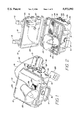
The major components of the present invention may be described with reference to FIGS. 1 and 2. A weather resistant case 10 is provided to house a cassette recorder 11 which provides either recording or playback of audio information. The weather resistant case 10 includes a bottom section 12 and a lid 13. The bottom section 12 and the lid 13 are each of molded one piece construction so as to present a continuous barrier to moisture infiltration into the interior of the case 10. A seal 14 between the bottom section 12 and the lid 13 provide for additional security against the entry of moisture and thus render the entire case 10 weather resistant when closed as shown in FIG. 1. The lid 13 is latched closed by means of latches 15 and since it is intended to be portable, it is provided with a handle 16. Since the case 10 is tightly sealed, changes in pressure inside and outside the case 10 can result in a lower air pressure inside the closed case 10 relative to the exterior atmosphere. As a result, a pressure relief valve 17 may be actuated to allow air into the interior of the case 10 so as to allow for opening of the lid 13.
For storage or transportation various components may be stowed within the case 10. FIG. 2 shows the radio transmitter 20 and the detachable radio receiver 21 stowed within the lid 13. The radio transmitter 20 and the radio receiver 21 may be attached to the lid 13 by means of hook and loop type fasteners of the velcro type or similar means. The radio receiver 21 is provided with an antenna 22. Sufficient space is provided within the lid 13 for stowing the antenna 22 with a minimal degree of bending.
The case 10 further provides storage space in the bottom section 12 for the external speaker 23. The external speaker 23 may be attached to the bottom section 12 using velcro type fasteners as described above with reference to the radio transmitter 20 and radio receiver 21. However, since the external speaker 23 is a rather heavy and bulky object, the preferred fastener is the dual-lock material manufactured by 3M. The dual-lock material is also preferred for attaching the external speaker 23 to the exterior of the case 10 as shown on FIG. 1. A dual-lock pad 24 is affixed to the top surface 25 of the lid 13. A complementary portion of dual-lock material is fastened to the base 26 of the external speaker 23. The external speaker 23 is thus removably attached to the exterior of the case 10 and may be removed for storage as shown in FIG. 2.
FIG. 1 shows the present invention as deployed for use. As noted above, the external speaker 23 is attached to the top surface 25 of the lid 13. The lid 13 is firmly closed so as to render the interior of the case 10 weather tight thereby protecting the cassette recorder 11 and additional circuitry located within the case 10 as will be described more completely hereafter. On the exterior 27 of the bottom portion 12, a 4-pin electrical connector 28 is disposed with a screw-on, waterproof cap 29. The 4-pin connector 28 is electrically connected to the circuitry in the interior of the case 10 and provides a point of connection for the speaker plug 30 which is electrically connected via a cable 31 to the external speaker 23.
Also disposed on the exterior 27 of the bottom portion 12 is an 8-pin connector 32 having a screw-on, waterproof cap 33. The 8-pin connector 32 is electrically connected to the circuitry in the interior of the case 10 and provides a point of connection for the detachable radio remote control receiver 21.
The exterior 27 of the bottom portion 12 also contains a volume control knob 34 which is electrically connected to the circuitry located in the interior of the case 10 for manual control when the radio remote control receiver 21 is not in use.
In order to convert the apparatus from the stored configuration shown in FIG. 2 to the operational configuration shown in FIG. 1, the latches 15 are released and the lid 13 raised to provide access to the interior of the case 10. The external speaker 23 is removed from the interior of the case 10 and by means of the dual-lock connectors disposed on the exterior surface 25 of the lid 13. The screw-on cap 29 of the 4-pin connector 28 is removed and the speaker plug 30 is plugged into the 4-pin connector 28. The screw-on cap 33 of the 8-pin connector 32 is removed. The detachable radio remote control receiver 21 is removed from the lid 13 and plugged into the 8-pin connector 32 by means of an 8-pin plug 35 which is electrically connected to the circuitry of the radio remote control receiver 21 as will be described more completely hereafter. The radio remote control transmitter is removed and retained by the user. The lid 13 is then placed in position against the seal 14 and the latch is operated to provide a complete weather resistant enclosure. The apparatus may then be placed in position by the hunter as appropriate. The hunter then retires to a distance from the apparatus. The hunter may then manually operate the radio remote control transmitter 20 so as to send signals to the remote control receiver 21. The remote control receiver 21 then transmits electrical signals to the interior circuitry of the case 10 in a manner that will be more completely described hereinafter so as to operate the cassette recorder 11. The output of the cassette recorder 11 is electrically connected to the external speaker 23 for reproduction of those sounds that have been recorded on the cassette recorder. The cassette recorder 11 may contain a tape having selected predator calls, game calls or the like. The radio remote control transmitter 20 may be used to turn the cassette recorder on and off and to adjust volume up and down.
In an alternative embodiment of the present invention, the external speaker 23 may be replaced or supplemented by an external microphone. When the cassette recorder is in the record mode the apparatus may be used to record sounds in the vicinity of the apparatus as opposed to reproducing sounds. In either embodiment, the apparatus may be operated manually as well as by means of the radio remote control receiver.
In addition, the radio remote control receiver 21 may be detached from one unit and used on another unit. It is thus possible to use a single remote control receiver in conjunction with more than one unit. This may be desirable for reasons of economy. Furthermore, the radio transmitter 20 may be programmed to activate more than one remote control receiver. The apparatus, therefore, may be used flexibly in a number of operational configurations.
The electronic circuitry of the present invention may be described generally with reference to FIG. 8. The radio transmitter 20 has been found to operate successfully based around a radio transmitter circuit available from Ming Engineering and Products, Inc., 17921 Rowland Street, City of Industry, Calif. 91748, known as the TX-66. The TX-66 is a 310 megahertz AM super-regenerative transmitter. The TX-66 accepts serial data sent from an encoder and transmits it to the receiver. The circuitry of the TX-66 transmitter 40 is described in FIG. 3. The encoding of the serial data transmitted to the TX-66 transmitter 40 is by means of the TX-66 interface circuitry 41 shown in FIG. 4. By manual operation of the switches, serial data is generated by HT-12E chip for transmission to the TX-66 transmitter 40. The TX-66 transmitter generates the radio signals 42 which are received by the antenna 22 of the radio remote control receiver 21. The radio remote control receiver 21 comprises a receiver circuit based on the RE-66 receiver 43 manufactured by Ming Engineering and Products, Inc. The RE-66 receiver 43 is designed to receive serial data from the TX-66 transmitter 40. The serial data received by the RE-66 receiver is decoded by the RE-66 interface 44. The detailed circuitry of the RE-66 receiver 43 is shown in FIG. 5. The RE-66 interface 44 is shown in FIGS. 6a and 6b. The serial data decoded by the RE-66 interface 44 is transmitted to the control circuitry 45 which is physically situated in the interior of the case 10. The control circuitry is shown in detail in FIGS. 7a through 7d. The serial data received by the receiver 43 is supplied to the control circuitry 45 for decoding so as to produce control signals for the cassette recorder 11. The output of the control circuitry 45 is transmitted to the cassette recorder 11 in order to control the functions of the cassette recorder. While the receiver and transmitter circuits have been described in terms of the particular circuitry available from Ming Engineering and Products, Inc., the scope of the present invention is not so limited. The prior art provides various forms of radio transmission, reception, and remote control circuitry which could be employed in the present invention as would be readily understood by one skilled in the art.
The present invention has been described with reference to certain preferred and alternative embodiments which are intended to be exemplary only and not limiting to the full scope of the present invention as embodied in the appended claims.

Claims (3)

What is claimed is:
1. A remote control audio apparatus for hunters, comprising:
a weather resistant enclosure having an exterior surface and an interior space;
audio means disposed within said interior space for reproduction and/or recording of predator calls, game calls and the like;
radio transmitter means for generating and transmitting operating radio signals under manual control;
radio receiver means for receiving said operating radio signals and generating electronic output signals responsive thereto;
control means disposed within said interior space and electronically communicating with said audio means and said radio receiver means, said control means being adapted to receiving said electronic output signals and to controlling operation of said audio means in response to said electronic output signal; and
an electronic plug connector disposed on said exterior surface and communicating electronically with said control means; and said radio receiver means further comprising a plug for detachable electronic connection to said plug connector whereby said electronic output signals are communicated to said control means.
2. The apparatus of claim 1, further comprising an external weather resistant speaker having a speaker plug means for detachably mounting said external speaker to said exterior surface, and a speaker plug connector disposed on said exterior surface and communicating electronically with said audio means whereby said speaker plug may be electronically connected to said audio means.
3. The apparatus of claim 2 further comprising storage means for removably storing said external speaker in said interior space.
US08/452,885 1995-05-30 1995-05-30 Remote control audio apparatus for hunters Expired - Fee Related US5572592A (en)

Priority Applications (1)

Application Number Priority Date Filing Date Title
US08/452,885 US5572592A (en) 1995-05-30 1995-05-30 Remote control audio apparatus for hunters

Applications Claiming Priority (1)

Application Number Priority Date Filing Date Title
US08/452,885 US5572592A (en) 1995-05-30 1995-05-30 Remote control audio apparatus for hunters

Publications (1)

Publication Number Publication Date
US5572592A true US5572592A (en) 1996-11-05

Family

ID=23798353

Family Applications (1)

Application Number Title Priority Date Filing Date
US08/452,885 Expired - Fee Related US5572592A (en) 1995-05-30 1995-05-30 Remote control audio apparatus for hunters

Country Status (1)

Country Link
US (1) US5572592A (en)

Cited By (31)

* Cited by examiner, † Cited by third party
Publication number Priority date Publication date Assignee Title
US6072392A (en) * 1998-08-10 2000-06-06 Jose Armando Coronado Apparatus and method for monitoring and recording the audible environment of a child, patient, older person or pet left in the care of a third person or persons
US6427070B1 (en) 1999-03-04 2002-07-30 Black & Decker Inc. Heavy-duty audio equipment
WO2004003871A2 (en) * 2002-06-27 2004-01-08 Stephen Cass Electronic training aide
US6757574B2 (en) 2000-01-14 2004-06-29 G&B Patent Holdings, Llc Methods and apparatus for producing animal sounds to lure animals
US6755714B1 (en) 2000-08-30 2004-06-29 Jerry R. Huddleston Remotely operable game caller
US20040147295A1 (en) * 1997-12-12 2004-07-29 Joseph Domes Ruggedized tradesworkers radio
US20050075045A1 (en) * 2003-07-28 2005-04-07 Williamson Zack A. Audio device for luring wildlife
US20050094825A1 (en) * 2003-10-30 2005-05-05 Loness Gene A. Remotely controlled sound generator
US20050102722A1 (en) * 2003-11-07 2005-05-12 Futaba Corporation Radio remote control unit with a playback function
US20060256973A1 (en) * 2005-04-19 2006-11-16 Eric Kirsten Method and apparatus for correlation and mobile playback of bird songs and animals calls
US20070033010A1 (en) * 2005-08-05 2007-02-08 Jones Lawrence P Remote audio surveillance for detection & analysis of wildlife sounds
US20070222623A1 (en) * 2006-03-20 2007-09-27 Mark Wiliams Method and system for producing animal sounds
US20080022322A1 (en) * 2006-06-30 2008-01-24 Sbc Knowledge Ventures L.P. System and method for home audio and video communication
US20080060249A1 (en) * 2006-07-18 2008-03-13 Dennis Stillwell Universal decoy system
US20080095382A1 (en) * 2006-10-06 2008-04-24 Mott Shannon R Audio system housed by an enclosure with a substantially waterproof seal
US7373110B1 (en) 2004-12-09 2008-05-13 Mcclain John Personal communication system, device and method
US20080159079A1 (en) * 2006-10-17 2008-07-03 Designlink, Llc Remotely Operable Game Call or Monitoring Apparatus
US20080170741A1 (en) * 2007-01-11 2008-07-17 Sceery Edward J Convenient electronic sound producing device
WO2009155348A1 (en) 2008-06-17 2009-12-23 Pandion Systems, Inc. System and method for detecting bats and their impact on wind facilities
US7741809B2 (en) 2006-01-06 2010-06-22 Milwaukee Electric Tool Corporation Electrical component including a battery receptacle for including a battery
US7835534B2 (en) 2003-10-14 2010-11-16 Robert Bosch Gmbh Battery charging jobsite lunchbox
US7868590B2 (en) 2001-11-09 2011-01-11 Milwaukee Electric Tool Corporation Electrical component, such as a radio, MP3 player, audio component, battery charger, radio/charger, MP3 player/radio, MP3 player/charger or MP3 player/radio/charger, having a selectively connectable battery charger
US20110113672A1 (en) * 2009-11-19 2011-05-19 Larry Holmberg Remote controlled decoy
US20120008464A1 (en) * 2010-07-09 2012-01-12 Barley Christopher B Electronic wildlife call
US8604752B2 (en) 2003-10-14 2013-12-10 Robert Bosch Gmbh Portable battery charging and audio unit
US20140304447A1 (en) * 2013-04-08 2014-10-09 Robert Louis Fils Method, system and apparatus for communicating with an electronic device and a stereo housing
US20140304446A1 (en) * 2013-04-08 2014-10-09 Robert Louis Fils Method,system and apparatus for communicating with an electronic device and stereo housing
US20160227758A1 (en) * 2015-02-11 2016-08-11 Paul Peoples Remote robotic can call system
US9762987B2 (en) 2015-09-09 2017-09-12 Wildlife Acoustics, Inc. Enclosure for supporting acoustic equipment
USD801683S1 (en) * 2015-09-09 2017-11-07 Wildlife Acoustics, Inc. Apparatus for supporting acoustic equipment
US9933810B2 (en) 2007-07-25 2018-04-03 Aquatic Av, Inc. Docking station for an electronic device

Citations (9)

* Cited by examiner, † Cited by third party
Publication number Priority date Publication date Assignee Title
US4050186A (en) * 1976-08-02 1977-09-27 Shults Otto C Sound producer
US4517564A (en) * 1981-09-21 1985-05-14 Tokyo Shibaura Denki Kabushiki Kaisha Cordless remote control apparatus
US4549179A (en) * 1983-03-04 1985-10-22 Stendardo William J Apparatus for remote control of volume and power on electronic equipment possessing an audio output
US4612001A (en) * 1984-11-28 1986-09-16 Burnham Bros. Game call
US4760547A (en) * 1985-09-24 1988-07-26 Duxbury Jonathan W Remote controlled multi-station irrigation system with DTMF transmitter
US4862625A (en) * 1988-11-25 1989-09-05 Dolan Rex H Remotely controlled turkey calling device
US4965953A (en) * 1989-07-10 1990-10-30 Mckinney Richard H Remote controlled turkey decoy
US5233780A (en) * 1992-04-24 1993-08-10 Overholt Dallas L Remotely controlled decoy and method
US5239587A (en) * 1992-02-14 1993-08-24 Bruce Muckelrath Sound recording device for use by hunters

Patent Citations (9)

* Cited by examiner, † Cited by third party
Publication number Priority date Publication date Assignee Title
US4050186A (en) * 1976-08-02 1977-09-27 Shults Otto C Sound producer
US4517564A (en) * 1981-09-21 1985-05-14 Tokyo Shibaura Denki Kabushiki Kaisha Cordless remote control apparatus
US4549179A (en) * 1983-03-04 1985-10-22 Stendardo William J Apparatus for remote control of volume and power on electronic equipment possessing an audio output
US4612001A (en) * 1984-11-28 1986-09-16 Burnham Bros. Game call
US4760547A (en) * 1985-09-24 1988-07-26 Duxbury Jonathan W Remote controlled multi-station irrigation system with DTMF transmitter
US4862625A (en) * 1988-11-25 1989-09-05 Dolan Rex H Remotely controlled turkey calling device
US4965953A (en) * 1989-07-10 1990-10-30 Mckinney Richard H Remote controlled turkey decoy
US5239587A (en) * 1992-02-14 1993-08-24 Bruce Muckelrath Sound recording device for use by hunters
US5233780A (en) * 1992-04-24 1993-08-10 Overholt Dallas L Remotely controlled decoy and method

Non-Patent Citations (5)

* Cited by examiner, † Cited by third party
Title
Brochure, Ming Engineering & Product, Inc., RE 66 310 MH 2 AM RF Receiver. *
Brochure, Ming Engineering & Product, Inc., RE-66 310 MH2 AM RF Receiver.
Brochure, Ming Engineering & Products, Inc., TX 66 310 MH 2 AM SAW Super Regenerative RE Transmitter. *
Brochure, Ming Engineering & Products, Inc., TX-66 310 MH2 AM SAW Super-Regenerative RE Transmitter.
Hunting, p. 24, Feb. 1996. *

Cited By (42)

* Cited by examiner, † Cited by third party
Publication number Priority date Publication date Assignee Title
USRE44557E1 (en) 1997-12-12 2013-10-22 Black & Decker Inc. Ruggedized tradesworkers radio
US20040147295A1 (en) * 1997-12-12 2004-07-29 Joseph Domes Ruggedized tradesworkers radio
US7043283B2 (en) 1997-12-12 2006-05-09 Black & Decker Inc. Ruggedized tradesworkers radio
US6072392A (en) * 1998-08-10 2000-06-06 Jose Armando Coronado Apparatus and method for monitoring and recording the audible environment of a child, patient, older person or pet left in the care of a third person or persons
US6427070B1 (en) 1999-03-04 2002-07-30 Black & Decker Inc. Heavy-duty audio equipment
US6757574B2 (en) 2000-01-14 2004-06-29 G&B Patent Holdings, Llc Methods and apparatus for producing animal sounds to lure animals
US20040243263A1 (en) * 2000-01-14 2004-12-02 G&B Patent Holdings, Llc Method and apparatus for producing animal sounds to lure animals
US6755714B1 (en) 2000-08-30 2004-06-29 Jerry R. Huddleston Remotely operable game caller
US7868590B2 (en) 2001-11-09 2011-01-11 Milwaukee Electric Tool Corporation Electrical component, such as a radio, MP3 player, audio component, battery charger, radio/charger, MP3 player/radio, MP3 player/charger or MP3 player/radio/charger, having a selectively connectable battery charger
US8203307B2 (en) 2001-11-09 2012-06-19 Milwaukee Electric Tool Corporation Audio and charging system with audio device, power tool battery, and external battery charger
WO2004003871A2 (en) * 2002-06-27 2004-01-08 Stephen Cass Electronic training aide
WO2004003871A3 (en) * 2002-06-27 2004-05-06 Stephen Cass Electronic training aide
US20050075045A1 (en) * 2003-07-28 2005-04-07 Williamson Zack A. Audio device for luring wildlife
US8604752B2 (en) 2003-10-14 2013-12-10 Robert Bosch Gmbh Portable battery charging and audio unit
US7835534B2 (en) 2003-10-14 2010-11-16 Robert Bosch Gmbh Battery charging jobsite lunchbox
US20050094825A1 (en) * 2003-10-30 2005-05-05 Loness Gene A. Remotely controlled sound generator
US20050102722A1 (en) * 2003-11-07 2005-05-12 Futaba Corporation Radio remote control unit with a playback function
US7373110B1 (en) 2004-12-09 2008-05-13 Mcclain John Personal communication system, device and method
US20060256973A1 (en) * 2005-04-19 2006-11-16 Eric Kirsten Method and apparatus for correlation and mobile playback of bird songs and animals calls
US8457962B2 (en) 2005-08-05 2013-06-04 Lawrence P. Jones Remote audio surveillance for detection and analysis of wildlife sounds
US20070033010A1 (en) * 2005-08-05 2007-02-08 Jones Lawrence P Remote audio surveillance for detection & analysis of wildlife sounds
US7741809B2 (en) 2006-01-06 2010-06-22 Milwaukee Electric Tool Corporation Electrical component including a battery receptacle for including a battery
US20070222623A1 (en) * 2006-03-20 2007-09-27 Mark Wiliams Method and system for producing animal sounds
US20080022322A1 (en) * 2006-06-30 2008-01-24 Sbc Knowledge Ventures L.P. System and method for home audio and video communication
US8051598B2 (en) * 2006-07-18 2011-11-08 Expedite International Universal decoy system
US20080060249A1 (en) * 2006-07-18 2008-03-13 Dennis Stillwell Universal decoy system
US7945067B2 (en) * 2006-10-06 2011-05-17 Shannon R. Mott Audio system housed by an enclosure with a substantially waterproof seal
US20080095382A1 (en) * 2006-10-06 2008-04-24 Mott Shannon R Audio system housed by an enclosure with a substantially waterproof seal
US20080159079A1 (en) * 2006-10-17 2008-07-03 Designlink, Llc Remotely Operable Game Call or Monitoring Apparatus
US20080170741A1 (en) * 2007-01-11 2008-07-17 Sceery Edward J Convenient electronic sound producing device
US9933810B2 (en) 2007-07-25 2018-04-03 Aquatic Av, Inc. Docking station for an electronic device
EP2316006A4 (en) * 2008-06-17 2017-03-08 Normandeau Associates, Inc. System and method for detecting bats and their impact on wind facilities
WO2009155348A1 (en) 2008-06-17 2009-12-23 Pandion Systems, Inc. System and method for detecting bats and their impact on wind facilities
US20110113672A1 (en) * 2009-11-19 2011-05-19 Larry Holmberg Remote controlled decoy
US20120008464A1 (en) * 2010-07-09 2012-01-12 Barley Christopher B Electronic wildlife call
US9042204B2 (en) * 2010-07-09 2015-05-26 Wgi Innovations, Ltd. Electronic wildlife call
US20140304447A1 (en) * 2013-04-08 2014-10-09 Robert Louis Fils Method, system and apparatus for communicating with an electronic device and a stereo housing
US20140304446A1 (en) * 2013-04-08 2014-10-09 Robert Louis Fils Method,system and apparatus for communicating with an electronic device and stereo housing
US9565851B2 (en) * 2015-02-11 2017-02-14 Paul Peoples Remote robotic can call system
US20160227758A1 (en) * 2015-02-11 2016-08-11 Paul Peoples Remote robotic can call system
US9762987B2 (en) 2015-09-09 2017-09-12 Wildlife Acoustics, Inc. Enclosure for supporting acoustic equipment
USD801683S1 (en) * 2015-09-09 2017-11-07 Wildlife Acoustics, Inc. Apparatus for supporting acoustic equipment

Similar Documents

Publication Publication Date Title
US5572592A (en) Remote control audio apparatus for hunters
US5838808A (en) Acoustical chair system
US4967696A (en) Dog collar
US6757574B2 (en) Methods and apparatus for producing animal sounds to lure animals
US10034457B2 (en) E-dog training mat
US5588398A (en) Remotely controlled dog muzzle
US5239587A (en) Sound recording device for use by hunters
WO1981000654A1 (en) Housing for electronic apparatus with elastomer outer layer
JPH0282968A (en) Method and apparatus for displaying delivery
US20040206310A1 (en) Voice receiver and annunciator for pets
US4833709A (en) Remote telephone signaling circuitry and device
US5828761A (en) Sound amplification system having a submersible microphone
US6885305B2 (en) System for locating and sending messages to pets
US5511560A (en) Method and apparatus for signaling parturition in large farm animals
GB2289604A (en) Bite indication system for anglers
US5409380A (en) System to assist the guiding of the non-sighted
GB2471410A (en) Handheld signal detector used for monitoring signal strength in a wireless alarm system
CN112602619A (en) Pet electronic collar based on image recognition
JP3115768U (en) Security camera device for dogs
GB2434070A (en) An accoustic animal deterrent device
US20030217442A1 (en) Remote control locating apparatus
JPH018124Y2 (en)
GB2221070A (en) An alarm adaptor for the deaf
JPH03128976U (en)
JP2009053881A (en) Crime prevention warning device

Legal Events

Date Code Title Description
AS Assignment

Owner name: R & L RESEARCH , LLC, ARKANSAS

Free format text: ASSIGNMENT OF ASSIGNORS INTEREST;ASSIGNORS:MUCKELRATH, BRUCE;CASTAGNO, JOE;REEL/FRAME:008307/0734

Effective date: 19961227

Owner name: CASTAGNO, JOE, ARKANSAS

Free format text: ASSIGNMENT OF ASSIGNORS INTEREST;ASSIGNOR:MUCKELRATH, BRUCE;REEL/FRAME:008307/0721

Effective date: 19961227

FPAY Fee payment

Year of fee payment: 4

REMI Maintenance fee reminder mailed
REFU Refund

Free format text: REFUND - PAYMENT OF MAINTENANCE FEE, 8TH YEAR, LARGE ENTITY (ORIGINAL EVENT CODE: R1552); ENTITY STATUS OF PATENT OWNER: LARGE ENTITY

Free format text: REFUND - 7.5 YR SURCHARGE - LATE PMT W/IN 6 MO, LARGE ENTITY (ORIGINAL EVENT CODE: R1555); ENTITY STATUS OF PATENT OWNER: LARGE ENTITY

REMI Maintenance fee reminder mailed
LAPS Lapse for failure to pay maintenance fees
STCH Information on status: patent discontinuation

Free format text: PATENT EXPIRED DUE TO NONPAYMENT OF MAINTENANCE FEES UNDER 37 CFR 1.362

FP Lapsed due to failure to pay maintenance fee

Effective date: 20081105