US5561544A - Laser scanning system with reflecting optics - Google Patents
Laser scanning system with reflecting optics Download PDFInfo
- Publication number
- US5561544A US5561544A US08/398,738 US39873895A US5561544A US 5561544 A US5561544 A US 5561544A US 39873895 A US39873895 A US 39873895A US 5561544 A US5561544 A US 5561544A
- Authority
- US
- United States
- Prior art keywords
- mirror
- laser beam
- mirrors
- optical path
- distance
- Prior art date
- Legal status (The legal status is an assumption and is not a legal conclusion. Google has not performed a legal analysis and makes no representation as to the accuracy of the status listed.)
- Ceased
Links
Images

Classifications
-
- B—PERFORMING OPERATIONS; TRANSPORTING
- B23—MACHINE TOOLS; METAL-WORKING NOT OTHERWISE PROVIDED FOR
- B23K—SOLDERING OR UNSOLDERING; WELDING; CLADDING OR PLATING BY SOLDERING OR WELDING; CUTTING BY APPLYING HEAT LOCALLY, e.g. FLAME CUTTING; WORKING BY LASER BEAM
- B23K26/00—Working by laser beam, e.g. welding, cutting or boring
- B23K26/02—Positioning or observing the workpiece, e.g. with respect to the point of impact; Aligning, aiming or focusing the laser beam
- B23K26/06—Shaping the laser beam, e.g. by masks or multi-focusing
-
- B—PERFORMING OPERATIONS; TRANSPORTING
- B23—MACHINE TOOLS; METAL-WORKING NOT OTHERWISE PROVIDED FOR
- B23K—SOLDERING OR UNSOLDERING; WELDING; CLADDING OR PLATING BY SOLDERING OR WELDING; CUTTING BY APPLYING HEAT LOCALLY, e.g. FLAME CUTTING; WORKING BY LASER BEAM
- B23K26/00—Working by laser beam, e.g. welding, cutting or boring
- B23K26/08—Devices involving relative movement between laser beam and workpiece
- B23K26/082—Scanning systems, i.e. devices involving movement of the laser beam relative to the laser head
-
- B—PERFORMING OPERATIONS; TRANSPORTING
- B23—MACHINE TOOLS; METAL-WORKING NOT OTHERWISE PROVIDED FOR
- B23K—SOLDERING OR UNSOLDERING; WELDING; CLADDING OR PLATING BY SOLDERING OR WELDING; CUTTING BY APPLYING HEAT LOCALLY, e.g. FLAME CUTTING; WORKING BY LASER BEAM
- B23K26/00—Working by laser beam, e.g. welding, cutting or boring
- B23K26/08—Devices involving relative movement between laser beam and workpiece
- B23K26/0869—Devices involving movement of the laser head in at least one axial direction
-
- G—PHYSICS
- G02—OPTICS
- G02B—OPTICAL ELEMENTS, SYSTEMS OR APPARATUS
- G02B26/00—Optical devices or arrangements for the control of light using movable or deformable optical elements
- G02B26/08—Optical devices or arrangements for the control of light using movable or deformable optical elements for controlling the direction of light
- G02B26/10—Scanning systems
- G02B26/105—Scanning systems with one or more pivoting mirrors or galvano-mirrors
-
- G—PHYSICS
- G02—OPTICS
- G02B—OPTICAL ELEMENTS, SYSTEMS OR APPARATUS
- G02B26/00—Optical devices or arrangements for the control of light using movable or deformable optical elements
- G02B26/08—Optical devices or arrangements for the control of light using movable or deformable optical elements for controlling the direction of light
- G02B26/10—Scanning systems
- G02B26/12—Scanning systems using multifaceted mirrors
- G02B26/124—Details of the optical system between the light source and the polygonal mirror
Definitions
- This invention relates to laser equipment which can both scan a laser beam and adjust the optical path to achieve a variable focal length of the laser beam.
- Laser scanning systems typically utilize galvanometer motors to change the angle of scanning mirrors. Usually the X and Y direction is scanned by separate motors. In many applications a laser beam is scanned on a work piece. To achieve a high power density, the laser beam is usually focused on this work piece. Specialized lens have been developed to achieve a good focus on a flat surface work piece even at a high transmission angle. However, some applications require that the laser beam can be independently focused to accommodate a contoured surface. Normally this focusing is accomplished by translating one or more lenses in an optical system to achieve a variable focal length. Unfortunately, high powered CO 2 lasers can cause a thermal distortion in lenses which degrades the quality of the laser beam. Furthermore, lenses are not as durable as metal mirrors for high power laser beam applications.
- the present invention is a laser scanning system with reflective optics. To achieve an adjustable focal length on the scanned laser beam it is necessary to produce an optical path length change between two mirrors which exhibit optical power (curved mirror surfaces). To achieve this, two additional flat mirrors oriented perpendicular to each other, are placed in the optical path between the curved mirrors. A displacement of the two perpendicular mirrors in a predetermined direction will change the optical path length between the curved mirrors and in turn produce an adjustable focus in the scanned beam without producing additional deviation to the scanned beam.
- FIG. 1 is a perspective view of an all reflective laser scanning system.
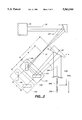
- FIG. 2 is a top view of an all reflective laser scanning system illustrating the optical components prior to the scanning mirrors.
- FIG. 1 shows a perspective view of an all reflective scanning system 10.
- a laser beam 20 propagating in the direction of arrow 28 strikes a curved reflector 11.
- reflector 11 is preferably an off axis parabola which focuses laser beam 20 to a focal point 21.
- This laser beam then strikes flat mirrors 12 and 13.
- the laser beam then strikes curved mirror 14.
- This curved mirror 14 is preferably an off axis ellipse.
- the laser beam then proceeds to strike scanning mirrors 15 and 16.
- These scanning mirrors can be rotated to steer the beam.
- mirror 15 can be rotated around the axis 25 and mirror 16 can be rotated around axis 26.
- a single scanning mirror could also be used.
- FIG. 1 illustrates the laser beam coming to a focus at three alternative focal spots designated 22A, 22B, or 22C. These are just used for illustration.
- the laser beam would only strike one point at a time.
- the actual focus point (22) will be referred to as the "external focus" because is lies outside the optical components.
- work piece 30 is illustrated as being a generally flat plate.
- mirrors 12 and 13 are approximately perpendicular to each other and mounted on base 17. These mirrors can be translated in a direction 27 while retaining their approximately relative orientation.
- Direction 27 is generally parallel to the beam propagation direction between focal point 21 and the center of the beam striking mirror 12.
- the four mirrors, 11, 12, 13, and 14 can be referred to as the 1st, 2nd, 3rd, and 4th mirrors respectively.
- FIG. 2 is the top view of a portion of the scanning system depicted in FIG. 1.
- laser 19 can be seen.
- laser beam 20 is shown to have a ray 20A which will be referred to as the "center line optical path".
- mirrors 12 and 13 as well as base 17 are shown in two different possible positions. These two positions are differentiated by adding the letters N or M to the numbers 12, 13, and 17. The translation required to produce this new position is distance E depicted in FIG. 2.
- FIG. 2 also shows point 23 which is defined as being the point at which the center line optical path 20A strikes mirror 14. Also, the distance from the focal point 21 to mirror 12 along the center line optical path is shown as being distance B.
- the center line optical path distance between mirror 13 and mirror 14 is defined as being distance D.
- the center line optical path between mirrors 12N and 13N or 12M and 13M is shown as being distance C.
- the center line optical path between the fourth mirror (point 23) and the external focal point 22M is shown being distance S(M). This focal point occurs when the mirror positions 12M and 13M are used. When mirror positions 12N and 13N are used, then focal point 22N is obtained at a distance of S(N) from point 23.
- the distance between focal points 22N and 22M [S(N)-S(M)] is not shown to scale when compared to displacement distance E depicted in FIG. 2.
- one of the advantages of placing the folding mirrors 12 and 13 in the optical path between mirror 11 and mirror 14, is that this location produces the largest possible change in focal length [S(N)-S(M)] for the smallest change in distance E. Also scanning mirrors 15 and 16 are shown in FIG. 1 but not shown in FIG. 2.
- Concave mirror 14 has an effective focal length "F" which is defined as being the focal length of a mirror when focusing parallel light. When the incident light is not parallel then the formula is:
- Distance S is defined as the optical path length to the external focal point 22 from the point 23. This is the predetermined portion of the laser beam which is scanned by scanning mirrors 15 and 16.
- the object of this invention is to prevent the focus adjustment from introducing a substantial scanning of this predetermined portion of the laser beam.
- the angle steering introduced by a change in the external focus should be kept less than 3 milliradians for each 10% change in distance S.
- Properly translating mirrors 12 and 13 in direction 27 (FIG. 1) while maintaining the perpendicular orientation will achieve this goal.
- mirror 11 is a concave off axis parabola.
- mirror 11 is a convex off axis parabola. If this was the case, then the rays reflecting off mirror 11 would appear to be diverging from mirror 11. These diverging rays would appear to come a virtual focus point behind mirror 11 and distance B would be measured from that virtual focus point. Focal point 21 would then be defined as this virtual focal point. Therefore, in either case it can be said that mirror 11 is a curved surface.
- Mirror 14 must always be a concave curved surface in order to function properly. It should also be understood that the preferred curvature for mirror 14 is an off axis ellipse.
- mirror 14 can be referred to as a concave curved surface.
- mirror 11 has been referred to as an off axis parabola. This is the preferred surface if laser beam 20 is generally parallel as illustrated. An off axis ellipse would be the preferred surface if laser beam 20 was either convergent or divergent.
- other curved surfaces such as a spherical surface could also produce acceptable results.
Abstract
Description
1/s+1/S=1/F
Claims (1)
Priority Applications (9)
| Application Number | Priority Date | Filing Date | Title |
|---|---|---|---|
| US08/398,738 US5561544A (en) | 1995-03-06 | 1995-03-06 | Laser scanning system with reflecting optics |
| JP8527069A JPH11501738A (en) | 1995-03-06 | 1996-03-06 | Laser scanner with reflective optics |
| AT96908730T ATE344469T1 (en) | 1995-03-06 | 1996-03-06 | LASER DEFLECTION SYSTEM WITH REFLECTION OPTICS |
| PT96908730T PT813696E (en) | 1995-03-06 | 1996-03-06 | Laser scanning system with reflective optics |
| DE69636668T DE69636668T2 (en) | 1995-03-06 | 1996-03-06 | LASER DEFLECTION SYSTEM WITH REFLECTION OPTICS |
| EP96908730A EP0813696B8 (en) | 1995-03-06 | 1996-03-06 | Laser scanning system with reflective optics |
| ES96908730T ES2276399T3 (en) | 1995-03-06 | 1996-03-06 | LASER SWEEP SYSTEM WITH REFLEXIVE OPTICS. |
| PCT/US1996/003208 WO1996027814A1 (en) | 1995-03-06 | 1996-03-06 | Laser scanning system with reflective optics |
| US09/136,710 USRE38165E1 (en) | 1995-03-06 | 1998-08-19 | Laser scanning system with reflecting optics |
Applications Claiming Priority (1)
| Application Number | Priority Date | Filing Date | Title |
|---|---|---|---|
| US08/398,738 US5561544A (en) | 1995-03-06 | 1995-03-06 | Laser scanning system with reflecting optics |
Related Child Applications (1)
| Application Number | Title | Priority Date | Filing Date |
|---|---|---|---|
| US09/136,710 Reissue USRE38165E1 (en) | 1995-03-06 | 1998-08-19 | Laser scanning system with reflecting optics |
Publications (1)
| Publication Number | Publication Date |
|---|---|
| US5561544A true US5561544A (en) | 1996-10-01 |
Family
ID=23576607
Family Applications (2)
| Application Number | Title | Priority Date | Filing Date |
|---|---|---|---|
| US08/398,738 Ceased US5561544A (en) | 1995-03-06 | 1995-03-06 | Laser scanning system with reflecting optics |
| US09/136,710 Expired - Lifetime USRE38165E1 (en) | 1995-03-06 | 1998-08-19 | Laser scanning system with reflecting optics |
Family Applications After (1)
| Application Number | Title | Priority Date | Filing Date |
|---|---|---|---|
| US09/136,710 Expired - Lifetime USRE38165E1 (en) | 1995-03-06 | 1998-08-19 | Laser scanning system with reflecting optics |
Country Status (8)
| Country | Link |
|---|---|
| US (2) | US5561544A (en) |
| EP (1) | EP0813696B8 (en) |
| JP (1) | JPH11501738A (en) |
| AT (1) | ATE344469T1 (en) |
| DE (1) | DE69636668T2 (en) |
| ES (1) | ES2276399T3 (en) |
| PT (1) | PT813696E (en) |
| WO (1) | WO1996027814A1 (en) |
Cited By (27)
| Publication number | Priority date | Publication date | Assignee | Title |
|---|---|---|---|---|
| US6078420A (en) * | 1998-06-24 | 2000-06-20 | Optical Engineering, Inc. | Hole-coupled laser scanning system |
| US6211988B1 (en) * | 1996-12-24 | 2001-04-03 | Leica Microsystems Heidelberg Gmbh | Optical device for scanning a beam in two axes that are substantially perpendicular to each other |
| EP1179747A1 (en) * | 2000-07-11 | 2002-02-13 | Leica Microsystems Heidelberg GmbH | Optical assembly for deflecting a light beam |
| US20050111066A1 (en) * | 2003-11-03 | 2005-05-26 | Sang Kyeong Yun | Scanning apparatus using a plurality of diffracted beams |
| US20050236381A1 (en) * | 2004-04-27 | 2005-10-27 | Disco Corporation | Laser beam processing machine |
| US20070053039A1 (en) * | 2005-02-25 | 2007-03-08 | Wolfgang Andreasch | Multi-station laser processing |
| US20090050611A1 (en) * | 2007-08-20 | 2009-02-26 | Universal Laser Systems, Inc. | Laser beam positioning systems for material processing and methods for using such systems |
| US20110127241A1 (en) * | 2008-05-17 | 2011-06-02 | Philp Thomas Rumsby | Method and apparatus for compensating for off-axis focal spot distortion |
| CN104728729A (en) * | 2013-12-19 | 2015-06-24 | 欧司朗有限公司 | Lighting device |
| US9182595B2 (en) | 2011-06-02 | 2015-11-10 | Nec Corporation | Image display devices |
| US20170015017A1 (en) * | 2015-07-16 | 2017-01-19 | Disco Corporation | Wafer producing method |
| US9789565B2 (en) | 2014-12-04 | 2017-10-17 | Disco Corporation | Wafer producing method |
| US9884390B2 (en) | 2014-12-04 | 2018-02-06 | Disco Corporation | Wafer producing method |
| US9925619B2 (en) | 2015-01-06 | 2018-03-27 | Disco Corporation | Wafer producing method |
| US10076804B2 (en) | 2015-02-09 | 2018-09-18 | Disco Corporation | Wafer producing method |
| US10081076B2 (en) | 2015-04-06 | 2018-09-25 | Disco Corporation | Wafer producing method |
| US10297438B2 (en) | 2015-04-06 | 2019-05-21 | Disco Corporation | Water producing method |
| US10319594B2 (en) | 2015-07-21 | 2019-06-11 | Disco Corporation | Wafer thinning method |
| US10319593B2 (en) | 2015-07-21 | 2019-06-11 | Disco Corporation | Wafer thinning method |
| US10369659B2 (en) | 2015-02-09 | 2019-08-06 | Disco Corporation | Wafer producing method |
| US10406635B2 (en) | 2016-04-11 | 2019-09-10 | Disco Corporattion | Wafer producing method and processing feed direction detecting method |
| US10610973B2 (en) | 2015-06-02 | 2020-04-07 | Disco Corporation | Wafer producing method |
| US10625371B2 (en) | 2015-04-06 | 2020-04-21 | Disco Corporation | Wafer producing method |
| CN111788513A (en) * | 2017-11-22 | 2020-10-16 | 傲科激光应用技术股份有限公司 | Electromagnetic radiation steering mechanism |
| US10828726B2 (en) | 2017-02-16 | 2020-11-10 | Disco Corporation | SiC wafer producing method using ultrasonic wave |
| CN112501419A (en) * | 2015-05-08 | 2021-03-16 | 爱科古恩A.I.E. | Method and apparatus for heat treatment of ferrous materials using an energy beam |
| US20210325639A1 (en) * | 2016-12-06 | 2021-10-21 | Samsung Display Co., Ltd. | Laser processing apparatus |
Families Citing this family (1)
| Publication number | Priority date | Publication date | Assignee | Title |
|---|---|---|---|---|
| JP2008203434A (en) * | 2007-02-19 | 2008-09-04 | Fujitsu Ltd | Scanning mechanism, method of machining material to be machined and machining apparatus |
Citations (5)
| Publication number | Priority date | Publication date | Assignee | Title |
|---|---|---|---|---|
| US4160939A (en) * | 1977-09-13 | 1979-07-10 | Xerox Corporation | Motor speed control system |
| US4232960A (en) * | 1979-02-21 | 1980-11-11 | Xerox Corporation | Scanning system |
| US4388651A (en) * | 1981-05-28 | 1983-06-14 | Lincoln Laser Co. | Method and apparatus for generating a scanned optical output signal |
| US5274492A (en) * | 1992-07-02 | 1993-12-28 | Mahmoud Razzaghi | Light spot size and shape control for laser projector |
| US5276546A (en) * | 1991-05-20 | 1994-01-04 | Butch Beaty | Three dimensional scanning system |
Family Cites Families (17)
| Publication number | Priority date | Publication date | Assignee | Title |
|---|---|---|---|---|
| US4461947A (en) | 1982-08-24 | 1984-07-24 | Allied Corporation | Rotating laser beam with coincident gas jet |
| US4469931A (en) | 1982-09-13 | 1984-09-04 | Macken John A | Laser assisted saw device |
| US4755999A (en) | 1985-03-25 | 1988-07-05 | Macken John A | Laser apparatus utilizing a magnetically enhanced electrical discharge |
| FR2580870B1 (en) * | 1985-04-23 | 1987-09-25 | Arnaud Jean | APPARATUS FOR REGULATING CHARACTERISTICS OF A LIGHT BEAM, IN PARTICULAR OF A POWER LASER |
| DE3709351A1 (en) * | 1987-03-21 | 1988-09-29 | Heraeus Gmbh W C | RADIATION GUIDE OPTICS FOR LASER RADIATION |
| US4941731A (en) | 1987-07-01 | 1990-07-17 | John Macken | Corner cube utilizing generally spherical surfaces |
| US4921338A (en) | 1989-05-09 | 1990-05-01 | Macken John A | Corrective optics for rectangular laser beams |
| US5206763A (en) | 1989-05-09 | 1993-04-27 | Macken John A | Corrective optics for rectangular laser beams |
| US5089683A (en) * | 1990-09-18 | 1992-02-18 | Union Carbide Coatings Service Technology Corporation | Device for producing a constant length laser beam and method for producing it |
| JP2736182B2 (en) | 1991-02-28 | 1998-04-02 | ファナック株式会社 | Laser device and laser welding method |
| US5142119A (en) | 1991-03-14 | 1992-08-25 | Saturn Corporation | Laser welding of galvanized steel |
| US5155323A (en) | 1991-05-16 | 1992-10-13 | John Macken | Dual focus laser welding |
| US5184012A (en) * | 1991-12-26 | 1993-02-02 | Olympus Optical Co., Ltd. | Optical scanning apparatus with axis deviation correction |
| US5237149A (en) | 1992-03-26 | 1993-08-17 | John Macken | Laser machining utilizing a spacial filter |
| JPH0679484A (en) | 1992-07-14 | 1994-03-22 | Mitsubishi Electric Corp | Laser welding method |
| US5528613A (en) | 1993-04-12 | 1996-06-18 | Macken; John A. | Laser apparatus utilizing a magnetically enhanced electrical discharge with transverse AC stabilization |
| DE9407288U1 (en) * | 1994-05-02 | 1994-08-04 | Trumpf Gmbh & Co | Laser cutting machine with focus position adjustment |
-
1995
- 1995-03-06 US US08/398,738 patent/US5561544A/en not_active Ceased
-
1996
- 1996-03-06 ES ES96908730T patent/ES2276399T3/en not_active Expired - Lifetime
- 1996-03-06 JP JP8527069A patent/JPH11501738A/en active Pending
- 1996-03-06 AT AT96908730T patent/ATE344469T1/en active
- 1996-03-06 WO PCT/US1996/003208 patent/WO1996027814A1/en active IP Right Grant
- 1996-03-06 PT PT96908730T patent/PT813696E/en unknown
- 1996-03-06 EP EP96908730A patent/EP0813696B8/en not_active Expired - Lifetime
- 1996-03-06 DE DE69636668T patent/DE69636668T2/en not_active Expired - Lifetime
-
1998
- 1998-08-19 US US09/136,710 patent/USRE38165E1/en not_active Expired - Lifetime
Patent Citations (5)
| Publication number | Priority date | Publication date | Assignee | Title |
|---|---|---|---|---|
| US4160939A (en) * | 1977-09-13 | 1979-07-10 | Xerox Corporation | Motor speed control system |
| US4232960A (en) * | 1979-02-21 | 1980-11-11 | Xerox Corporation | Scanning system |
| US4388651A (en) * | 1981-05-28 | 1983-06-14 | Lincoln Laser Co. | Method and apparatus for generating a scanned optical output signal |
| US5276546A (en) * | 1991-05-20 | 1994-01-04 | Butch Beaty | Three dimensional scanning system |
| US5274492A (en) * | 1992-07-02 | 1993-12-28 | Mahmoud Razzaghi | Light spot size and shape control for laser projector |
Cited By (39)
| Publication number | Priority date | Publication date | Assignee | Title |
|---|---|---|---|---|
| US6211988B1 (en) * | 1996-12-24 | 2001-04-03 | Leica Microsystems Heidelberg Gmbh | Optical device for scanning a beam in two axes that are substantially perpendicular to each other |
| EP1090321A4 (en) * | 1998-06-24 | 2009-04-08 | Optical Engineering Inc | Hole-coupled laser scanning system |
| EP1090321A1 (en) * | 1998-06-24 | 2001-04-11 | Optical Engineering, Inc. | Hole-coupled laser scanning system |
| US6078420A (en) * | 1998-06-24 | 2000-06-20 | Optical Engineering, Inc. | Hole-coupled laser scanning system |
| EP1179747A1 (en) * | 2000-07-11 | 2002-02-13 | Leica Microsystems Heidelberg GmbH | Optical assembly for deflecting a light beam |
| CN100367071C (en) * | 2003-11-03 | 2008-02-06 | 三星电机株式会社 | Scanner with multiple diffraction beams |
| US7218433B2 (en) | 2003-11-03 | 2007-05-15 | Samsung Electro-Mechanics Co., Ltd. | Scanning apparatus using a plurality of diffracted beams |
| US20050111066A1 (en) * | 2003-11-03 | 2005-05-26 | Sang Kyeong Yun | Scanning apparatus using a plurality of diffracted beams |
| US7459655B2 (en) * | 2004-04-27 | 2008-12-02 | Disco Corporation | Laser beam processing machine |
| US20050236381A1 (en) * | 2004-04-27 | 2005-10-27 | Disco Corporation | Laser beam processing machine |
| CN100479969C (en) * | 2004-04-27 | 2009-04-22 | 株式会社迪斯科 | Laser beam processing machine |
| US20070053039A1 (en) * | 2005-02-25 | 2007-03-08 | Wolfgang Andreasch | Multi-station laser processing |
| US20090050611A1 (en) * | 2007-08-20 | 2009-02-26 | Universal Laser Systems, Inc. | Laser beam positioning systems for material processing and methods for using such systems |
| US8294062B2 (en) * | 2007-08-20 | 2012-10-23 | Universal Laser Systems, Inc. | Laser beam positioning systems for material processing and methods for using such systems |
| US20110127241A1 (en) * | 2008-05-17 | 2011-06-02 | Philp Thomas Rumsby | Method and apparatus for compensating for off-axis focal spot distortion |
| US9796046B2 (en) * | 2008-05-17 | 2017-10-24 | M-Solv Ltd. | Method and apparatus for compensating for off-axis focal spot distortion |
| US9182595B2 (en) | 2011-06-02 | 2015-11-10 | Nec Corporation | Image display devices |
| US9482412B2 (en) | 2013-12-19 | 2016-11-01 | Osram Gmbh | Lighting device |
| DE102013226614A1 (en) * | 2013-12-19 | 2015-06-25 | Osram Gmbh | lighting device |
| CN104728729A (en) * | 2013-12-19 | 2015-06-24 | 欧司朗有限公司 | Lighting device |
| US9789565B2 (en) | 2014-12-04 | 2017-10-17 | Disco Corporation | Wafer producing method |
| US9884390B2 (en) | 2014-12-04 | 2018-02-06 | Disco Corporation | Wafer producing method |
| US9925619B2 (en) | 2015-01-06 | 2018-03-27 | Disco Corporation | Wafer producing method |
| US10076804B2 (en) | 2015-02-09 | 2018-09-18 | Disco Corporation | Wafer producing method |
| US10369659B2 (en) | 2015-02-09 | 2019-08-06 | Disco Corporation | Wafer producing method |
| US10625371B2 (en) | 2015-04-06 | 2020-04-21 | Disco Corporation | Wafer producing method |
| US10297438B2 (en) | 2015-04-06 | 2019-05-21 | Disco Corporation | Water producing method |
| US10081076B2 (en) | 2015-04-06 | 2018-09-25 | Disco Corporation | Wafer producing method |
| CN112501419A (en) * | 2015-05-08 | 2021-03-16 | 爱科古恩A.I.E. | Method and apparatus for heat treatment of ferrous materials using an energy beam |
| US10610973B2 (en) | 2015-06-02 | 2020-04-07 | Disco Corporation | Wafer producing method |
| US10029383B2 (en) * | 2015-07-16 | 2018-07-24 | Disco Corporation | Wafer producing method |
| US20170015017A1 (en) * | 2015-07-16 | 2017-01-19 | Disco Corporation | Wafer producing method |
| US10319593B2 (en) | 2015-07-21 | 2019-06-11 | Disco Corporation | Wafer thinning method |
| US10319594B2 (en) | 2015-07-21 | 2019-06-11 | Disco Corporation | Wafer thinning method |
| US10406635B2 (en) | 2016-04-11 | 2019-09-10 | Disco Corporattion | Wafer producing method and processing feed direction detecting method |
| US20210325639A1 (en) * | 2016-12-06 | 2021-10-21 | Samsung Display Co., Ltd. | Laser processing apparatus |
| US10828726B2 (en) | 2017-02-16 | 2020-11-10 | Disco Corporation | SiC wafer producing method using ultrasonic wave |
| CN111788513A (en) * | 2017-11-22 | 2020-10-16 | 傲科激光应用技术股份有限公司 | Electromagnetic radiation steering mechanism |
| CN111788513B (en) * | 2017-11-22 | 2023-12-05 | 傲科激光应用技术股份有限公司 | Electromagnetic radiation steering mechanism |
Also Published As
| Publication number | Publication date |
|---|---|
| EP0813696A4 (en) | 1998-10-14 |
| EP0813696A1 (en) | 1997-12-29 |
| WO1996027814A1 (en) | 1996-09-12 |
| ES2276399T3 (en) | 2007-06-16 |
| ATE344469T1 (en) | 2006-11-15 |
| EP0813696B1 (en) | 2006-11-02 |
| DE69636668T2 (en) | 2007-09-06 |
| PT813696E (en) | 2007-02-28 |
| USRE38165E1 (en) | 2003-07-01 |
| JPH11501738A (en) | 1999-02-09 |
| EP0813696B8 (en) | 2007-01-17 |
| DE69636668D1 (en) | 2006-12-14 |
Similar Documents
| Publication | Publication Date | Title |
|---|---|---|
| US5561544A (en) | Laser scanning system with reflecting optics | |
| US8139294B2 (en) | Techniques for steering an optical beam | |
| JPH0627904B2 (en) | Laser beam scanning optics | |
| JPH0727125B2 (en) | Optical scanning device | |
| EP1090321B1 (en) | Hole-coupled laser scanning system | |
| JPH07199109A (en) | Raster scanning system | |
| JPH1096859A (en) | Optical structure | |
| US5004311A (en) | Beam scanning method and apparatus | |
| US5828481A (en) | Mid-objective laser scanner | |
| US3873180A (en) | Light beam scanning system with scan angle demagnification | |
| US4643516A (en) | Laser beam scanning apparatus | |
| US6888680B2 (en) | Optical arrangement for obtaining information from a sample or an observed object | |
| US7297898B2 (en) | Laser processing machine | |
| US4953926A (en) | Scanning optical system for use in a laser beam printer | |
| JP2002062499A (en) | Scanning optical device | |
| US5306892A (en) | Mirror objective arrangement | |
| JP3003065B2 (en) | Optical scanning device | |
| JP3381333B2 (en) | Optical scanning device | |
| CN117687177A (en) | Transmission type cylindrical optical system | |
| JPH02100014A (en) | Astigmatism compensation optical system | |
| US6515783B2 (en) | Penta assembly skew compensator | |
| JPH01108519A (en) | Luminous flux adjusting method for scan type optical device | |
| JPH04212121A (en) | Optical scanner | |
| JP2002318360A (en) | Optical element for synthesizing beams, method for synthesizing beams, light source device, and multibeam scanner | |
| JPH09145991A (en) | Anisotropic refracting power lens |
Legal Events
| Date | Code | Title | Description |
|---|---|---|---|
| STCF | Information on status: patent grant |
Free format text: PATENTED CASE |
|
| AS | Assignment |
Owner name: OPTICAL ENGINEERING, INC., CALIFORNIA Free format text: ASSIGNMENT OF ASSIGNORS INTEREST;ASSIGNOR:MACKEN, JOHN A.;REEL/FRAME:008732/0213 Effective date: 19970916 |
|
| RF | Reissue application filed |
Effective date: 19980819 |
|
| FEPP | Fee payment procedure |
Free format text: PAT HLDR NO LONGER CLAIMS SMALL ENT STAT AS SMALL BUSINESS (ORIGINAL EVENT CODE: LSM2); ENTITY STATUS OF PATENT OWNER: LARGE ENTITY |
|
| REMI | Maintenance fee reminder mailed | ||
| FPAY | Fee payment |
Year of fee payment: 4 |
|
| SULP | Surcharge for late payment | ||
| AS | Assignment |
Owner name: UTICA ENTERPRISES, INC. A CORPORATION OF MICHIGAN, Free format text: SECURITY AGREEMENT;ASSIGNOR:OPTICAL ENGINEERING, INC. A CORPORATION OF CALIFORNIA;REEL/FRAME:011648/0734 Effective date: 20010124 Owner name: CARTER, THOMAS, MICHIGAN Free format text: SECURITY AGREEMENT;ASSIGNOR:OPTICAL ENGINEERING, INC. A CORPORATION OF CALIFORNIA;REEL/FRAME:011648/0734 Effective date: 20010124 Owner name: WANCZYK, STEFAN, MICHIGAN Free format text: SECURITY AGREEMENT;ASSIGNOR:OPTICAL ENGINEERING, INC. A CORPORATION OF CALIFORNIA;REEL/FRAME:011648/0734 Effective date: 20010124 |