US5558309A - Convertible structure comprising a plurality of adjacent seats and of variable size along a sliding axis - Google Patents

Convertible structure comprising a plurality of adjacent seats and of variable size along a sliding axis Download PDF

Info

Publication number
US5558309A
US5558309A US08/358,004 US35800494A US5558309A US 5558309 A US5558309 A US 5558309A US 35800494 A US35800494 A US 35800494A US 5558309 A US5558309 A US 5558309A
Authority
US
United States
Prior art keywords
cam
moving portion
structure according
sliding
longitudinal
Prior art date
Legal status (The legal status is an assumption and is not a legal conclusion. Google has not performed a legal analysis and makes no representation as to the accuracy of the status listed.)
Expired - Fee Related
Application number
US08/358,004
Inventor
Robert R. L. Marechal
Current Assignee (The listed assignees may be inaccurate. Google has not performed a legal analysis and makes no representation or warranty as to the accuracy of the list.)
INDUSTRIELLE ET COMMERCIALE DE MATERIEL Ste
Safran Seats SA
Original Assignee
Societe Industrielle et Commerciale de Materiel Aeronautique SICMA Aero Seat SA
Priority date (The priority date is an assumption and is not a legal conclusion. Google has not performed a legal analysis and makes no representation as to the accuracy of the date listed.)
Filing date
Publication date
Family has litigation
First worldwide family litigation filed litigation Critical https://patents.darts-ip.com/?family=9454084&utm_source=google_patent&utm_medium=platform_link&utm_campaign=public_patent_search&patent=US5558309(A) "Global patent litigation dataset” by Darts-ip is licensed under a Creative Commons Attribution 4.0 International License.
Application filed by Societe Industrielle et Commerciale de Materiel Aeronautique SICMA Aero Seat SA filed Critical Societe Industrielle et Commerciale de Materiel Aeronautique SICMA Aero Seat SA
Assigned to SOCIETE INDUSTRIELLE ET COMMERCIALE DE MATERIEL reassignment SOCIETE INDUSTRIELLE ET COMMERCIALE DE MATERIEL ASSIGNMENT OF ASSIGNORS INTEREST (SEE DOCUMENT FOR DETAILS). Assignors: MARECHAL, ROBERT RENE LUCIEN
Application granted granted Critical
Publication of US5558309A publication Critical patent/US5558309A/en
Anticipated expiration legal-status Critical
Expired - Fee Related legal-status Critical Current

Links

Images

Classifications

    • BPERFORMING OPERATIONS; TRANSPORTING
    • B64AIRCRAFT; AVIATION; COSMONAUTICS
    • B64DEQUIPMENT FOR FITTING IN OR TO AIRCRAFT; FLIGHT SUITS; PARACHUTES; ARRANGEMENTS OR MOUNTING OF POWER PLANTS OR PROPULSION TRANSMISSIONS IN AIRCRAFT
    • B64D11/00Passenger or crew accommodation; Flight-deck installations not otherwise provided for
    • B64D11/06Arrangements of seats, or adaptations or details specially adapted for aircraft seats
    • B64D11/0693Width modification of seat assemblies, e.g. for class modification

Landscapes

  • Engineering & Computer Science (AREA)
  • Aviation & Aerospace Engineering (AREA)
  • Seats For Vehicles (AREA)

Abstract

A structure comprising a plurality of adjacent seats for a public passenger vehicle, in particular an airliner, the structure being convertible and of variable size along a sliding axis (100), and comprising:
a fixed portion (2) comprising at least two transverse underframes (4) that are spaced apart from each other, fixed to the floor of the passenger cabin, and rigidly connected to one another by longitudinal underframe elements (5) having an axis that is generally parallel to the sliding axis;
at least one moving portion (3) that is movable relative to the fixed portion between two extreme positions, namely a maximum-size first position and a minimum-size second position, the moving portion (3) including an end transverse seat side member (6) rigidly associated with longitudinal support elements (7), and intermediate transverse seat side members (8) parallel to the end transverse seat side member (6) and associated with the longitudinal support elements (6), and serving to mount seat backs and arms; and
locking elements for locking the moving portion (3) to the fixed portion (2) in each of the two extreme positions;
wherein each longitudinal underframe element (5) includes at least two sliding support elements (9) secured to the longitudinal underframe element (5) for sliding along an axis that is parallel to and distinct from the general axis of the associated longitudinal underframe element (5), with a longitudinal support element (7) of the moving portion (3) being slidably received therein and guided in translation along the sliding axis (100).

Description

FIELD OF THE INVENTION
The invention relates to a convertible structure comprising a plurality of adjacent seats and that is of variable size along a sliding axis.
The invention relates in particular to such a structure intended for use in public passenger vehicles, and in particular airliners.
BACKGROUND OF THE INVENTION
At present, airlines need to be able to adapt the passenger cabin of a given aircraft as a function of occupancy rates in the various comfort and tariff classes.
Thus, between two consecutive flights, airlines frequently need to change tourist class seats for business class seats, for example, or vice versa. Various methods and devices are presently available for that purpose. The first method consists in removing the seats entirely and in replacing them with seats of a different size. Such changeovers take too long and cannot in general be performed by crew members. That type of changeover is generally performed by specialized personnel during overnight maintenance.
In order to improve productivity, airlines are now tending to reduce stopover times between two flights quite considerably, since the cost of an airplane on the ground severely degrades productivity.
U.S. Pat. No. 3, 893,729 relates to a structure comprising a plurality of adjacent seats that are convertible between different comfort class sizes. That structure includes a support underframe carrying a plurality of adjacent seats. Each seat is independent from the others. Changing over to a higher comfort class consists in removing certain seats from each row (e.g. two seats from a row of eight), causing all of the remaining seats to slide along the support underframe, and adding an additional element to each of them for the purpose of increasing their width. The seats that have been removed are stored in the airplane's cargo hold. Such devices make it possible to perform maintenance operations more quickly and may even be performed by crew members. There nevertheless remains the need to put the seats that have been removed into the cargo hold and to bring out the additional elements needed for widening the remaining seats.
In addition, that type of device is convertible only and does not allow for the general size of the structure to be reduced on changing from eight adjacent seats to six wider seats.
EP-A-0 322 930, EP-A-0 433 664, EP-A-0 530 923, and EP-A-0 530 920 relate to structures comprising a plurality of adjacent seats suitable for public passenger vehicles, and combining convertibility with size reduction.
Those structures comprise a fixed portion comprising at least two transverse underframes that are spaced apart, fixed to the floor of the cabin, and connected rigidly to one another by longitudinal underframe elements having a general axis parallel to a sliding axis. The structure includes a moving portion comprising at least one tube that is coaxial with the longitudinal elements, slidably engaged with the longitudinal elements of the underframe, and carrying a plurality of adjacent rigid seat frames. The structure also includes a locking and release mechanism placed at one end of the first seat frame. Operation is as follows: by acting on the locking and release mechanism, the tube or tubes is/are allowed to slide in the longitudinal underframe elements, thereby providing a structure of a size that can be varied by moving the adjacent seat frames towards one another or away from one another. The convertibility function is achieved by sacrificing a seat onto which two arm rests are brought so that the two seats immediately adjacent thereto gain extra width.
Such a structure relies on a sliding coupling with tube engagement. The drawback of tube engagement is that it is difficult to maintain, and in particular to clean. Accumulated dust can cause tube-on-tube sliding to jam.
Another drawback comes from the fact that sliding takes place over a substantial fraction of the tubes. Consequently, the slightest deformation of one or other of the tubes, particularly the long-term effect of the repeated application of the weight of various occupants of the seats, tends to make axial sliding difficult.
SUMMARY OF THE INVENTION
The object of the present invention si to provide a structure comprising a plurality of adjacent seats, being of convertible type and of variable size, and mitigating the drawbacks mentioned above.
To this end, the invention provides a structure comprising a plurality of adjacent seats for a public passenger vehicle, in particular an airliner, the structure being convertible and of variable size along a sliding axis, and comprising: a fixed portion comprising at least two transverse underframes that are spaced apart from each other, fixed to the floor of the cabin, and rigidly connected to one another by longitudinal underframe elements having an axis that is generally parallel to the sliding axis; at least one moving portion that is slidably movable relative to the fixed portion between two extreme positions, namely a maximum-size first position and a minimum-size second position, said moving portion including an end transverse seat side member rigidly associated with longitudinal support elements, and intermediate transverse seat side members parallel to the end transverse seat side member and associated with the longitudinal support elements, and serving to mount seat backs and arms. The structure also includes locking means for locking the moving portion to the fixed portion in each of the two extreme positions.
According to the invention, each longitudinal underframe element includes at least two sliding support elements secured to the longitudinal underframe element for sliding along an axis that is parallel to and distinct from the general axis of the associated longitudinal underframe element, with a longitudinal support element of the moving portion being slidably received therein and guided in translation along the sliding axis. Such a structure relying on sliding by means of sliding support elements that are offset relative to the longitudinal elements of the underframe makes it possible to restrict the sliding zones considerably. That has the effect firstly of limiting the extent to which the sliding zones become dirtied, of providing easier access to said sliding zones, and of limiting jamming effects due to the sliding means deforming.
Another advantage of the present invention is based on the fact that the connection between the sliding support elements and the underframe longitudinal element can advantageously include a shock-absorbing device in addition to or in place of those that already exist conventionally on tranverse underframes.
BRIEF DESCRIPTION OF THE DRAWINGS
Other advantages appear from the following description) given with reference to the accompanying drawings, in which:
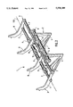
FIG. 1 is a three-quarters outside view of a structure of the present invention having one moving portion and shown in its minimum size position.
FIG. 2 is a three-quarters outside view of a structure of the present invention having two moving portions And shown in its minimum size position.
FIG. 3 fragmentary longitudinal section through an embodiment of the present invention.
FIG. 4 is a front view of the axial lock, and a front view, partially in section, of the manual actuator device in an embodiment of the invention.
DETAILED DESCRIPTION OF THE INVENTION
The invention relates to a structure 1 comprising a plurality of adjacent seats for public passenger vehicles, in particular airliners, which structure is convertible and of variable size along a sliding axis 100. In the description below, the terms "transverse", "axial", and "longitudinal" should be understood relative to the sliding axis 100.
The structure shown in the drawings and described in the present application relates to a variable-size structure having three adjacent seats.
By way of non-limiting example, the structure may serve to convert three tourist class seats into two higher-comfort class seats occupying a smaller amount of space overall. The structure can thus also serve to increase inter-seat spacing so as to limit passenger crowding.
This structure 1 comprises a fixed portion 2 and a moving portion 3.
In the embodiment shown in the figures, the fixed portion comprises at least two transverse underframes 4 that are spaced apart from each other and fixed to the floor of the passenger cabin of a public passenger vehicle, the underframes being rigidly connected together by longitudinal underframe elements 5 having an axis that extends generally parallel to the sliding axis 100.
Each longitudinal underframe element comprises at least two sliding support elements 9 secured to the longitudinal underframe element 5 having an axis parallel to and different from the general axis of the longitudinal underframe element 5 associated therewith.
A longitudinal support element 7 forming a part of the moving portion 3 is slidably received in the sliding support element 9 and is guided thereby in translation along the sliding axis 100.
The, or each, moving portion 3 further comprises an end transverse seat side member 6 rigidly associated with the longitudinal elements 7, and intermediate transverse seat side members 8 parallel to the end transverse seat side member 6 and associated with the longitudinal support elements 7.
The end transverse seat side members 6 and the intermediate transverse seat side members 8 are disposed so as to enable seat backs and seat arms to be mounted thereon.
The intermediate transverse seat side members 8 are slidable relative to the support elements 7 with which they are associated.
This characteristic is important insofar as it enables the frame of each seat to be compressed or expanded, which is not possible in the prior art since the frame elements of those seats are all rigidly associated in translation along the sliding axis.
Advantageously, the support elements 7 include drive abutments (not shown) disposed at predetermined locations for driving the intermediate transverse seat side members 8 in translation along the sliding axis 100 over a previously-chosen distance that may optionally be different from the distance through which the, or each, end transverse seat side member is caused to slide.
In a first embodiment of the invention, as shown in FIG. 1, one of the end transverse seat side members 6, given reference 10, is rigidly associated with the longitudinal underframe elements 5, with only one end seat side member 6 being movable. This configuration is particularly advantageous when the structure is positioned adjacent to a wall of the cabin of the public passenger vehicle.
In a second embodiment shown in FIG. 2, each of the end transverse seat side members 6 is rigidly associated with a respective different moving portion 3. In this configuration, the two seat ends 6 are movable independently of each other.
The, or each, moving portion slides relative to the fixed portion 2 along the sliding axis 100 between two extreme positions, namely a first or "maximum size" position and a second or "minimum size" position (FIGS. 1 and 2).
The structure includes means for locking the moving portion(s) 3 to the fixed portion 2 in each of the two end positions.
Advantageously, the locking means include abutments (not shown) for limiting sliding motion between the two end positions, and safety means for locking the moving portion 3 in one or other of its two extreme positions.
The changeover from one of the extreme positions to the other is performed by means of a removable manual actuator device 18 that is made safe. Safety is provided by the manual actuator device 18 being retained by the structure so long as it has not been locked in translation.
In the embodiment shown in FIG. 3, the safety means for locking the moving portion in one of the extreme positions are disposed in part inside one of the longitudinal support elements 7. To this end, the longitudinal support element 7 is hollow.
In addition to the hollow longitudinal support element 7, the safety means for locking the moving portion 3 in one of its two end positions comprise a rod 11 mounted coaxially inside the hollow longitudinal support element 7, free to rotate about the axis of hollow support element, and opening out at one of its ends to the outside face 12 of the moving end transverse seat side member 6, while its other end has a cam 13. The cam 13 is designed to co-operate with two radial grooves 14a and 14b formed on the underframe element 5 associated with the hollow longitudinal support element 7 via the sliding supports 9, which are fitted with ball-bearing socket 20. The grooves 14a and 14b are disposed in such a manner that in the first position, the cam co-operates with the first groove 14b to lock the moving portion 3 against translation, while in the second position, the cam co-operates with the second groove 14a for achieving the same result.
Advantageously, the safety means for locking the moving portion 3 in one of the two extreme positions includes a system 28, 19 for complementary engagement in the groove 14a or 14b, such as a system comprising a ball 28 that co-operates with a cavity 19, by way of non-limiting example. The ball 28 and the cavity 19 can equally well be located at the end of the cam 13 and at the bottom of the groove 14a and 14b, or vice versa.
In addition, the rod 11 may be associated with a resilient element forcing it to return the cam 13 into a cam-engaged position.
Finally, the end 16 opening out in the outside face 12 of the end transverse seat side member 6 may advantageously include an axial safety lock 17 designed to co-operate with the removable manual actuator device 18 so as to enable rotary motion to be imparted to the rod 11 for the purpose of changing over from one position to the other.
In the embodiment shown in FIG. 4, the axial safety lock 17 and the manual actuator device 18 co-operate with each other in such a manner that:
if the cam is initially wrongly positioned in the groove, the manual actuator device cannot be associated with the axial lock;
if the cam is initially properly positioned in one or other of the grooves, then the manual actuator device can be inserted into the axial lock, but can no longer be removed therefrom unless the cam is properly positioned in one or other of the grooves.
For this purpose, the axial lock 17 includes radial studs 21 secured to the end transverse seat side member 6, and a diametral projection 22 at the end 16 of the rod 11; the actuator device has two radial notches 24 at an end 23, with the axial length h' of the notches being no greater than the axial depth of the lock, and a diametral slot 25 designed to co-operate with the diametral projection 22.
The lock operates as follows:
When the cam 13 is not properly positioned in a groove, the radial notches 24 are not in register with the projections 21 so the face 26 of the device is locked by the projections 21 preventing the device from being withdrawn.
Thus, changeover from one of the positions to the other takes place as follows:
the manual actuator device 18 is inserted into the axial lock 17, thereby constraining the rod 11 to rotate with the manual actuator device 18;
the manual actuator device 18 is used to rotate the rod 11 and thus disengage the cam 13 from one of the grooves 14a or 14b;
the moving portion is slid towards its other position;
the rod 11 is rotated in the opposite direction to engage the cam 13 in the other groove 14a or 14b;
the manual actuator device 18 is withdrawn from the axial safety lock 19 providing the cam 13 is properly engaged in the groove.
Advantageously, the rigid connection between the sliding support 9 and the longitudinal elements of the underframe 5 can include respective energy absorbing devices in addition to or in place of the energy absorbing devices conventionally disposed on the transverse underframes 4.

Claims (18)

I claim:
1. A structure comprising a plurality of adjacent seats for a public passenger vehicle, in particular an airliner, the structure being convertible and of variable size along a sliding axis (100), and comprising:
a fixed portion (2) comprising at least two transverse underframes (4) that are spaced apart from each other, fixed to the floor of the passenger cabin, and rigidly connected to one another by longitudinal underframe elements (5) having an axis that is generally parallel to the sliding axis;
at least one moving portion (3) that is movable relative to the fixed portion between two extreme positions, namely a maximum-size first position and a minimum-size second position, said moving portion (3) including an end transverse seat side member (6) rigidly associated with longitudinal support elements (7), and intermediate transverse seat side members (8) parallel to the end transverse seat side member (6) and associated with the longitudinal support elements (6), and serving to mount seat backs and arms; and
locking means for locking the moving portion (3) to the fixed portion (2) in each of the two extreme positions;
wherein each longitudinal underframe element (5) includes at least two sliding supports (9) secured to the longitudinal underframe element (5) for sliding along an axis that is parallel to and distinct from the general axis of the associated longitudinal underframe element (5), with a longitudinal support element (7) of the moving portion (3) being slidably received therein and guided in translation along the sliding axis (100).
2. A structure according to claim 1, wherein the intermediate transverse seat side members (8) are slidable relative to the support elements (7) with which they are associated.
3. A structure according to claim 2, wherein the support elements (7) drives said intermediate transverse seat side members (8) in translation along the sliding axis (100) over a previously-chosen distance that is not necessarily the same as the displacement distance of the moving portion (3).
4. A structure according to claim 1, wherein the locking means comprises safety means for locking the moving portion (3) in each of the two extreme positions.
5. A structure according to claim 4, wherein at least one of the longitudinal support elements (7) of each moving portion (3) is hollow, and wherein the safety means comprises a rod (11) coaxially mounted inside the hollow support element (7), free to rotate about the axis of said support element, opening out to one of its ends (16) in an outside face (12) of the end transverse seat side member (6), and having a cam (13) at its other end (15), two grooves (14a, 14b) being provided in the associated underframe element (5) in such a manner that when the cam (13) is in the first position it co-operates with the first groove (14b) to lock the moving portion (3) in translation, and when the cam is in its second position it co-operates with the second groove (14a), changeover between the two positions being achieved firstly by rotating the rod (11) so as to disengage the cam from one of the grooves (14a, 14b); then by sliding the moving portion (3) towards the other position; and then by rotating the rod (11) in the opposite direction to engage the cam (13) in the other groove (14a, 14b).
6. A structure according to claim 5, wherein the end (16) opening out in the outside face (12) of the end transverse seat side member (6) has an axial safety lock (17) designed to co-operate with a removable manual actuator device (18) that enables rotary motion to be imparted to the rod (11) in order to pass from one position to the other, which device is prevented from being removed so long as the cam (13) is not correctly positioned in one or other of the grooves (14a, 14b).
7. A structure according to claims 6, wherein the cam (13) is properly positioned in one or other of the grooves (14a, 14b) by means of a system comprising a ball (28) that co-operates with a cavity (19), one of the ball and cavity being disposed in the bottom of the groove and the other at a radial end of the cam.
8. A structure according to claim 7, wherein the sliding supports (9) are fitted with ball-bearing sockets (20).
9. A structure according to claim 8, wherein the rod (11) is urged into a cam position that causes the cam (13) to be engaged in one or other of the grooves (14a, 14b).
10. A structure according to claim 4, wherein the safety means for locking the moving portion (3) in either extreme position comprises a manual actuator device that is made safe by being retained by the structure unless it has been properly locked in position against translation.
11. A structure according to claim 10, wherein at least one of the longitudinal support elements (7) of each moving portion (3) is hollow, and wherein the safety means comprise a rod (11) coaxially mounted inside the hollow support element (7), free to rotate about the axis of said support element, opening out to one its end (16) in the outside face (12) of an end transverse seat side member (6), and having a cam (13) at its other end (15), two grooves (14a, 14b) being provided in the associated underframe element (5) in such a manner that when the cam (13) is in the first position it co-operates with the first groove (14b) to lock the moving portion (3) in translation, and when the cam is in its second position it co-operates with the second groove (14a), changeover between the two positions being achieved firstly by rotating the rod (11) so as to disengage the cam from one of the grooves (14a, 14b); then by sliding the moving portion (3) towards the other position; and then by rotating the rod (11) in the opposite direction to engage the cam (13) in the other groove (14a, 14b).
12. A structure according to claim 11, wherein the end (16) opening out in the outside face (12) of the end transverse seat side member (6) has an axial safety lock (17) designed to co-operate with a removable manual actuator device (18) that enables rotary motion to be imparted to the rod (11) in order to pass from one position to the other, which device is prevented from being removed so long as the cam (13) is not correctly positioned in one or other of the grooves (14a, 14b).
13. A structure according to claim 12, wherein the cam (13) is properly positioned in one or other of the grooves (14a, 14b) by means of a system comprising a ball (28) that co-operates with a cavity (19), one of the ball and cavity being disposed in the bottom of the groove and the other at a radial end of the cam.
14. A structure according to claim 13, wherein the sliding supports (9) are fitted with ball-bearing sockets (20).
15. A structure according to claim 14, wherein that rod (11) is urged into a cam position that causes the cam (13) to be engaged in one or other of the grooves (14a, 14b).
16. A structure according to claim 1, wherein one of the end transverse seat side members (10) is rigidly associated with the longitudinal underframe elements (5) so that only one of the seat ends (6) is movable.
17. A structure according to claim 1, wherein each of the end transverse seat side members (6) is rigidly associated with a moving portion (3), each of the two seat ends (10) being movable independently of the other.
18. A structure according to claim 1, wherein the rigid connections between the sliding supports (9) and the longitudinal underframe elements (5) are constituted by links that absorb energy in the event of major acceleration due to an accidental collision of the public passenger vehicle.
US08/358,004 1993-12-17 1994-12-16 Convertible structure comprising a plurality of adjacent seats and of variable size along a sliding axis Expired - Fee Related US5558309A (en)

Applications Claiming Priority (2)

Application Number Priority Date Filing Date Title
FR9315256A FR2714020B1 (en) 1993-12-17 1993-12-17 Structure with several adjacent convertible seats and variable dimensions along a sliding axis.
FR9315256 1993-12-17

Publications (1)

Publication Number Publication Date
US5558309A true US5558309A (en) 1996-09-24

Family

ID=9454084

Family Applications (1)

Application Number Title Priority Date Filing Date
US08/358,004 Expired - Fee Related US5558309A (en) 1993-12-17 1994-12-16 Convertible structure comprising a plurality of adjacent seats and of variable size along a sliding axis

Country Status (5)

Country Link
US (1) US5558309A (en)
EP (1) EP0658477B1 (en)
JP (1) JPH07223594A (en)
DE (2) DE69404818T2 (en)
FR (1) FR2714020B1 (en)

Cited By (26)

* Cited by examiner, † Cited by third party
Publication number Priority date Publication date Assignee Title
US5671975A (en) * 1995-04-19 1997-09-30 Eisen- Und Drahtwerk Erlau Aktiengesellschaft Seating system with horizontal bar having seat portions connected thereto
US5810290A (en) * 1995-06-07 1998-09-22 Keiper Recaro Gmbh & Co. Vehicle seating rows, particularly airplane passenger seating rows
US5957407A (en) * 1996-08-14 1999-09-28 The Boeing Company Convertible seat systems for wide body aircraft
US6691970B1 (en) 2002-07-22 2004-02-17 Aerospace Systems & Components, Inc. Rotatable seat support
US6820932B2 (en) 2001-12-06 2004-11-23 Kmcor Llc Computer bench
WO2005035301A2 (en) * 2003-10-06 2005-04-21 B/E Aerospace, Inc. A reclining chair
US20050264085A1 (en) * 2004-05-27 2005-12-01 Airbus Deutschland Gmbh Double-spar chassis for aircraft passenger seat
US20070080258A1 (en) * 2005-09-06 2007-04-12 Andreas Baatz Modular seat system for a vehicle
US20070145789A1 (en) * 2005-12-22 2007-06-28 Linero Luis G Aircraft seat assembly
US20070252420A1 (en) * 2006-05-01 2007-11-01 Fasco Industries, Inc. Automotive power seat motor arrangement including a monolithic frame
US20090013723A1 (en) * 2007-07-09 2009-01-15 Kristine Coulter Jewelery adapter
US20100109400A1 (en) * 2008-10-31 2010-05-06 Kneller Heidi J Adjustable width seats
DE102008062113A1 (en) * 2008-12-16 2010-06-17 Zim Gmbh Skeleton for a passenger seat row
US20110068226A1 (en) * 2005-09-06 2011-03-24 Airbus Deutschland Gmbh Modular seat system for a vehicle
WO2014011320A1 (en) * 2012-07-10 2014-01-16 Molon Lab, Llc Slider seat for aircraft
US9359079B2 (en) 2011-07-11 2016-06-07 Molon Labe Llc Slider seat for aircraft
IT201700024741A1 (en) * 2017-03-06 2018-09-06 Geven S P A Support base for aircraft seats and related set of seats side by side
USD840701S1 (en) 2017-10-18 2019-02-19 Molon Labe, Llc Staggered aircraft seats
USD850177S1 (en) 2017-12-15 2019-06-04 Molon Labe, Llc Aircraft seat armrests
US10427056B2 (en) * 2016-10-26 2019-10-01 Bec Gmbh Seating device
USD867775S1 (en) 2018-04-03 2019-11-26 Molon Labe, Llc Set of multilevel aircraft seat armrests
USRE47872E1 (en) 2011-07-11 2020-02-25 Molon Labe Llc Slider seat for aircraft
US10569881B2 (en) 2016-10-18 2020-02-25 Molon Labe, Llc Staggered aircraft seat assembly
USD924043S1 (en) 2019-08-22 2021-07-06 Molon Labe, Llc Aircraft wheelchair accommodating seat assembly
USD936383S1 (en) 2019-08-01 2021-11-23 Molon Labe, Llc Staggered aircraft seat assembly
US11260774B2 (en) * 2020-04-13 2022-03-01 Freedman Seating Company Modular transportation seat frame

Families Citing this family (4)

* Cited by examiner, † Cited by third party
Publication number Priority date Publication date Assignee Title
DE19534024C2 (en) * 1995-09-14 1997-07-10 Daimler Benz Aerospace Airbus Seating group, in particular in a passenger cabin of an aircraft
FR2774644B1 (en) * 1998-02-12 2003-12-05 Gec Alsthom Transport Sa FIRST-SECOND CLASS MODULAR TWO-SEAT BENCH AND PROCESS FOR CONVERTING SUCH A BENCH
FR2774645B1 (en) * 1998-02-12 2003-12-05 Gec Alsthom Transport Sa BENCH TWO PLACES OF SECOND CLASS MODULAR IN BANQUETTE A PLACE OF FIRST CLASS AND REVERSE AND METHOD FOR CONVERTING SUCH A BANQUETTE
DE102009014720A1 (en) * 2009-03-27 2010-09-30 Recaro Aircraft Seating Gmbh & Co. Kg Seat frame device

Citations (7)

* Cited by examiner, † Cited by third party
Publication number Priority date Publication date Assignee Title
US3743351A (en) * 1971-07-20 1973-07-03 C Harris Laterally expandable couch
US3893729A (en) * 1974-11-18 1975-07-08 Mc Donnell Douglas Corp Convertible passenger seat
US4881702A (en) * 1987-12-29 1989-11-21 The Boeing Company Readily convertible aircraft passenger seats
US5104065A (en) * 1990-02-20 1992-04-14 The Boeing Company Readily convertible aircraft passenger seats
US5131607A (en) * 1990-02-20 1992-07-21 The Boeing Company Extendable and retractable aircraft seat assembly
US5178345A (en) * 1990-02-20 1993-01-12 The Boeing Company Extendible and retractable aircraft seat assembly
US5509722A (en) * 1994-04-15 1996-04-23 Burns Aerospace Corporation Convertible passenger seat assembly and grouping of passenger seat assemblies

Family Cites Families (4)

* Cited by examiner, † Cited by third party
Publication number Priority date Publication date Assignee Title
FR1025269A (en) * 1950-09-29 1953-04-13 Fr Carrosserie Gangloff Soc Sliding seat
US2742952A (en) * 1953-05-12 1956-04-24 Bellamy Clyde Hampson Movable seat
FR1128852A (en) * 1954-08-23 1957-01-11 Bremshey & Co Double seat, especially for vehicles
IL100123A0 (en) * 1991-11-21 1992-08-18 Israel Aircraft Ind Ltd Improved multi-passenger seating assembly

Patent Citations (7)

* Cited by examiner, † Cited by third party
Publication number Priority date Publication date Assignee Title
US3743351A (en) * 1971-07-20 1973-07-03 C Harris Laterally expandable couch
US3893729A (en) * 1974-11-18 1975-07-08 Mc Donnell Douglas Corp Convertible passenger seat
US4881702A (en) * 1987-12-29 1989-11-21 The Boeing Company Readily convertible aircraft passenger seats
US5104065A (en) * 1990-02-20 1992-04-14 The Boeing Company Readily convertible aircraft passenger seats
US5131607A (en) * 1990-02-20 1992-07-21 The Boeing Company Extendable and retractable aircraft seat assembly
US5178345A (en) * 1990-02-20 1993-01-12 The Boeing Company Extendible and retractable aircraft seat assembly
US5509722A (en) * 1994-04-15 1996-04-23 Burns Aerospace Corporation Convertible passenger seat assembly and grouping of passenger seat assemblies

Cited By (49)

* Cited by examiner, † Cited by third party
Publication number Priority date Publication date Assignee Title
US5671975A (en) * 1995-04-19 1997-09-30 Eisen- Und Drahtwerk Erlau Aktiengesellschaft Seating system with horizontal bar having seat portions connected thereto
US5810290A (en) * 1995-06-07 1998-09-22 Keiper Recaro Gmbh & Co. Vehicle seating rows, particularly airplane passenger seating rows
US5957407A (en) * 1996-08-14 1999-09-28 The Boeing Company Convertible seat systems for wide body aircraft
US6012679A (en) * 1996-08-14 2000-01-11 The Boeing Company Convertible seat systems for wide body aircraft
US20050104425A1 (en) * 2001-12-06 2005-05-19 Krisann Misthos Computer bench
US6820932B2 (en) 2001-12-06 2004-11-23 Kmcor Llc Computer bench
US6691970B1 (en) 2002-07-22 2004-02-17 Aerospace Systems & Components, Inc. Rotatable seat support
US20060208550A1 (en) * 2003-10-06 2006-09-21 B/E Aerospace, Inc. Reclining chair
WO2005035301A3 (en) * 2003-10-06 2006-01-19 Be Aerospace Inc A reclining chair
US20060181118A1 (en) * 2003-10-06 2006-08-17 B/E Aerospace, Inc. Reclining chair
US20050168042A1 (en) * 2003-10-06 2005-08-04 B/E Aerospace, Inc. Reclining chair
US20060214482A1 (en) * 2003-10-06 2006-09-28 B/E Aerospace, Inc. Reclining chair
US7159937B2 (en) 2003-10-06 2007-01-09 B/E Aerospace, Inc. Reclining chair
US7182403B2 (en) 2003-10-06 2007-02-27 B/E Aerospace, Inc. Reclining chair
US7195319B2 (en) * 2003-10-06 2007-03-27 B/E Aerospace, Inc. Reclining chair
WO2005035301A2 (en) * 2003-10-06 2005-04-21 B/E Aerospace, Inc. A reclining chair
US7210740B2 (en) 2003-10-06 2007-05-01 B/E Aerospace, Inc. Reclining chair
US7399037B2 (en) * 2004-05-27 2008-07-15 Airbus Deutschland Gmbh Double-spar chassis for aircraft passenger seat
US20050264085A1 (en) * 2004-05-27 2005-12-01 Airbus Deutschland Gmbh Double-spar chassis for aircraft passenger seat
US7857259B2 (en) * 2005-09-06 2010-12-28 Airbus Deutschland Gmbh Modular seat system for a vehicle
US20070080258A1 (en) * 2005-09-06 2007-04-12 Andreas Baatz Modular seat system for a vehicle
US8870119B2 (en) 2005-09-06 2014-10-28 Airbus Operations Gmbh Modular seat system for a vehicle
US20110068226A1 (en) * 2005-09-06 2011-03-24 Airbus Deutschland Gmbh Modular seat system for a vehicle
US20070145789A1 (en) * 2005-12-22 2007-06-28 Linero Luis G Aircraft seat assembly
US7578551B2 (en) 2005-12-22 2009-08-25 Airbus Uk Limited Aircraft seat assembly
US20070252420A1 (en) * 2006-05-01 2007-11-01 Fasco Industries, Inc. Automotive power seat motor arrangement including a monolithic frame
US20090013723A1 (en) * 2007-07-09 2009-01-15 Kristine Coulter Jewelery adapter
US20100109400A1 (en) * 2008-10-31 2010-05-06 Kneller Heidi J Adjustable width seats
US8028958B2 (en) * 2008-10-31 2011-10-04 The Boeing Company Adjustable width seats
DE102008062113A1 (en) * 2008-12-16 2010-06-17 Zim Gmbh Skeleton for a passenger seat row
US20110303790A1 (en) * 2008-12-16 2011-12-15 Zim Gmbh Frame for a flight passenger seating row
WO2010072358A3 (en) * 2008-12-16 2010-08-19 Zim Gmbh Frame for a flight passenger seating row
DE102008062113B4 (en) * 2008-12-16 2020-01-23 Zim Gmbh Skeleton for a row of passenger seats
USRE47872E1 (en) 2011-07-11 2020-02-25 Molon Labe Llc Slider seat for aircraft
US8708410B2 (en) 2011-07-11 2014-04-29 Molon Labe Llc Slider seat for aircraft
US9359079B2 (en) 2011-07-11 2016-06-07 Molon Labe Llc Slider seat for aircraft
CN104640773B (en) * 2012-07-10 2016-12-14 墨龙拉布有限责任公司 The sliding seat of aircraft
WO2014011320A1 (en) * 2012-07-10 2014-01-16 Molon Lab, Llc Slider seat for aircraft
CN104640773A (en) * 2012-07-10 2015-05-20 墨龙拉布有限责任公司 Slider seat for aircraft
US10569882B2 (en) 2016-10-18 2020-02-25 Molon Labe, Llc Staggered aircraft seat assembly
US10569881B2 (en) 2016-10-18 2020-02-25 Molon Labe, Llc Staggered aircraft seat assembly
US10427056B2 (en) * 2016-10-26 2019-10-01 Bec Gmbh Seating device
IT201700024741A1 (en) * 2017-03-06 2018-09-06 Geven S P A Support base for aircraft seats and related set of seats side by side
USD840701S1 (en) 2017-10-18 2019-02-19 Molon Labe, Llc Staggered aircraft seats
USD850177S1 (en) 2017-12-15 2019-06-04 Molon Labe, Llc Aircraft seat armrests
USD867775S1 (en) 2018-04-03 2019-11-26 Molon Labe, Llc Set of multilevel aircraft seat armrests
USD936383S1 (en) 2019-08-01 2021-11-23 Molon Labe, Llc Staggered aircraft seat assembly
USD924043S1 (en) 2019-08-22 2021-07-06 Molon Labe, Llc Aircraft wheelchair accommodating seat assembly
US11260774B2 (en) * 2020-04-13 2022-03-01 Freedman Seating Company Modular transportation seat frame

Also Published As

Publication number Publication date
EP0658477B1 (en) 1997-08-06
DE69404818T2 (en) 1997-11-27
FR2714020B1 (en) 1996-01-12
JPH07223594A (en) 1995-08-22
DE69404818D1 (en) 1997-09-11
FR2714020A1 (en) 1995-06-23
DE658477T1 (en) 1995-12-14
EP0658477A1 (en) 1995-06-21

Similar Documents

Publication Publication Date Title
US5558309A (en) Convertible structure comprising a plurality of adjacent seats and of variable size along a sliding axis
EP3572325B1 (en) Deployable partition systems and methods for seat assemblies
JP3032313B2 (en) Passenger seat assembly and passenger seat structure
US5131607A (en) Extendable and retractable aircraft seat assembly
DE69821513T2 (en) PILLOW DEVICE FOR MOVING PERSONS
AU671382B2 (en) Armrest arrangements in convertible aircraft passenger seating
US3637253A (en) Laterally slidable seat
CN101821125B (en) Vehicle seat
EP0847917B1 (en) Reduced head impact seat system
US20160194084A1 (en) Vehicle occupant support
DE19534024A1 (en) Seat group for passenger compartment of aircraft
EP3526120B1 (en) Contoured class divider
US7222916B2 (en) Energy absorbing device and shoulder belt-type vehicle seats comprising such energy absorbing device
CN114599583A (en) Passenger seat unit with multi-slide push-slide door
DE102008036253B4 (en) Integrated child seat with special functions
CN107826232B (en) Aircraft cockpit area, aircraft comprising such an aircraft cockpit area and method for operating such an aircraft
US10259586B2 (en) Deployable seat assembly, system, and method for an interior cabin of a vehicle
EP0227239B1 (en) Adjustable- width seating for vehicles
CN108859877B (en) Seat device for motor vehicle
DE102021106948A1 (en) Device for accommodating at least one occupant and/or luggage in a vehicle and method for operating the device
EP2433833A2 (en) Seat or seat assembly for a motor vehicle, in particular a delivery vehicle
EP1034975A2 (en) Vehicle seat
DE102022205195A1 (en) Vehicle seat arrangement with a transversely adjustable seat part
EP3019402B1 (en) Vehicle occupant support
US10124898B2 (en) Seat bench device with a seat bench component and at least one restraining unit

Legal Events

Date Code Title Description
AS Assignment

Owner name: SOCIETE INDUSTRIELLE ET COMMERCIALE DE MATERIEL, F

Free format text: ASSIGNMENT OF ASSIGNORS INTEREST;ASSIGNOR:MARECHAL, ROBERT RENE LUCIEN;REEL/FRAME:007267/0427

Effective date: 19940801

FEPP Fee payment procedure

Free format text: PAYOR NUMBER ASSIGNED (ORIGINAL EVENT CODE: ASPN); ENTITY STATUS OF PATENT OWNER: LARGE ENTITY

FEPP Fee payment procedure

Free format text: PAYER NUMBER DE-ASSIGNED (ORIGINAL EVENT CODE: RMPN); ENTITY STATUS OF PATENT OWNER: LARGE ENTITY

FPAY Fee payment

Year of fee payment: 4

REMI Maintenance fee reminder mailed
LAPS Lapse for failure to pay maintenance fees
FP Lapsed due to failure to pay maintenance fee

Effective date: 20040924

STCH Information on status: patent discontinuation

Free format text: PATENT EXPIRED DUE TO NONPAYMENT OF MAINTENANCE FEES UNDER 37 CFR 1.362