US5549577A - Needleless connector - Google Patents
Needleless connector Download PDFInfo
- Publication number
- US5549577A US5549577A US08/174,843 US17484393A US5549577A US 5549577 A US5549577 A US 5549577A US 17484393 A US17484393 A US 17484393A US 5549577 A US5549577 A US 5549577A
- Authority
- US
- United States
- Prior art keywords
- connector
- housing
- plunger
- elastomeric
- blunt cannula
- Prior art date
- Legal status (The legal status is an assumption and is not a legal conclusion. Google has not performed a legal analysis and makes no representation as to the accuracy of the status listed.)
- Expired - Lifetime
Links
Images

Classifications
-
- A—HUMAN NECESSITIES
- A61—MEDICAL OR VETERINARY SCIENCE; HYGIENE
- A61M—DEVICES FOR INTRODUCING MEDIA INTO, OR ONTO, THE BODY; DEVICES FOR TRANSDUCING BODY MEDIA OR FOR TAKING MEDIA FROM THE BODY; DEVICES FOR PRODUCING OR ENDING SLEEP OR STUPOR
- A61M39/00—Tubes, tube connectors, tube couplings, valves, access sites or the like, specially adapted for medical use
- A61M39/02—Access sites
- A61M39/04—Access sites having pierceable self-sealing members
- A61M39/045—Access sites having pierceable self-sealing members pre-slit to be pierced by blunt instrument
Definitions
- This invention generally relates to connectors of the type used in the handling and administration of parenteral fluids and, more particularly, to a connector adapted to make sterile connections in medical systems without the use of a sharp cannula.
- Injection sites for injecting or removing fluid from a system are wellknown and widely used.
- Conventional injection sites generally involve a pierceable septum formed of an elastomeric material such as latex rubber or the like, captured in an access port.
- the housing of the septum may be, for example, the Y-body of a conventional Y-site component of an IV delivery set.
- a sharp cannula is inserted into the access port, piercing the septum, and a distal end of the cannula is positioned distal of the septum. In this way a fluid connection is made with the Anterior of the access port through the inserted cannula.
- the elastomeric septum Upon withdrawal of the sharp cannula, the elastomeric septum reseals the puncture made by the now-withdrawn cannula.
- a sterile environment can be maintained within the housing of the injection site.
- the outer surface of the septum of the injection site is wiped with an antiseptic before each use to prevent septic agents from being drawn into the access port by the piercing movement of the needle.
- connectors for accommodating injection and withdrawal of fluids without the use of sharp cannulas have been used in increasing numbers instead of conventional injection sites. This is, at least in part, due to concern regarding the transmission of blood-borne diseases through accidental needle punctures of the person handling the sharp cannula. Connectors having no sharpened surfaces are desirable because the chances of inadvertently piercing the operator's skin are lessened.
- needleless connectors allow fluid flow in only one direction, or require some further manipulation after a connection is established to allow fluid flow in both directions. Both of these characteristics are undesirable because they limit the usefulness of the connector.
- a further concern in the design of needleless connectors is the order of occurrences in which the connection is made. For example, allowing fluid to escape or air to enter during connection due to the female connector being opened before the male connector is sufficiently seated are undesirable.
- some existing connectors accommodate a relatively large interior fluid volume, requiring injection of a commensurately large volume of fluid just to fill the connector. If not taken into account, this fluid volume can detract from the volume of medicament injected and may be clinically significant. An inconvenient separate flushing procedure may be required in low dose injections or in the injection of unstable medicines due to this relatively large interior volume.
- a further concern regarding the design of a needleless connector is that it should not accommodate a conventional sharp needle. Where such connectors can be used with sharp and blunt cannulas, the deterrent effect with regard to using sharp needles to make fluid connections, with an associated reduction in the number of accidental needle sticks, is potentially compromised.
- needleless connectors be configured so that they can be easily cleaned by an antiseptic wipe or otherwise sterilized prior to making a connection. All exterior surfaces that may be involved in the transmission of fluid should be available for cleaning prior to the connection being made.
- Some prior connectors have a small rift or fissure, defined by a clearance between parts or an elastomeric element that is not under sufficient compression, at the proximal or connecting end. Such a feature is difficult and inconvenient to clean in attempting to sterilize a connector.
- connectors requiring a cap to maintain a sterile connection port are undesirable because the extra steps of removing and replacing a cap are inconvenient for medical personnel.
- a needleless connector Another important characteristic of a needleless connector is its ability to hold a vacuum from a distal side. That is to say, if a vacuum is applied to the interior of the connector, the connector should not admit air. This becomes an increased concern in connectors that have been used at least once. Adverse consequences may result if a connector cannot hold a vacuum, for example, some automated infusion pumps wall pull a vacuum in a tubing line under certain circumstances. Needlelees connectors that will not hold a vacuum, incorporated in an infusion get used with such a pump, may admit air when no connector or cap is attached, which may in turn cause a potentially harmful air embolism in a patient.
- the invention provides a needleless connector of relatively simple design and few parts which is intuitive to use and which is relatively inexpensive to manufacture, accommodates a high flow rate, is more easily cleaned before use, and does not require a protective cap.
- the design minimizes unwanted fluid and air leakage, has minimal interior fluid volume and "dead space,” and is not compatible with a sharp needle, thereby reducing accidental needle punctures of medical personnel.
- the connector of the invention includes a housing having first and second ends, defining a chamber therebetween, the first end defining a connection port.
- a blunt cannula is carried by the housing within the chamber, the blunt cannula having a fluid passage therethrough in fluid communication with the second end of the housing.
- An elastomeric pro-slit plunger is movably disposed in the housing in a first position within the connector. In this first position the elastomeric pro-slit plunger sealingly occludes the passage through the cannula at the proximal end of the cannula. When moved to a second position within the chamber the elastomeric pro-slit plunger is penetrated by said blunt cannula so that the first and second ends of the housing are in fluid communication by means of the passage through said blunt cannula.
- a biasing means is included for biasing the plunger to the first position within the chamber.
- This biasing means is, for example, either a deformable spring-like or other elastic member, a pressurized gas within the chamber, or a combination of both.
- the elastomeric plunger when the elastomeric plunger is in the first position, it is flush with the first end of the connector.
- the elastomeric plunger is in radial compression in this area, eliminating any annular crack or fissure that might otherwise exist between the plunger and the housing, and the slit portion is held tightly shut.
- the connector can be easily cleaned, for example with an alcohol swipe, to sterilize it before connection.
- a significant portion of the fluid pathway between the first and second ends of the connector 10, in making a fluid connection comprises the blunt cannula 30, which has a small fluid volume associated with it. Consequently, the connector as a whole defines a flow channel therethrough that has a relatively small interior fluid volume, reducing the need for flushing. At the same time, the connector can accommodate a relatively high fluid flow rate, as the flow channel is straight and is not restricted. Dead space associated with the connector is commensurately small.
- the blunt cannula can be formed unitary with the housing member. This results in three component parts being required if a two-piece housing is used.
- the connector of the invention with its simple construction and small number of parts provides manufacturing cost savings, as well as enhancing safety, reliability and ease of use in preparing medications and treating patients.
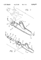
- FIG. 1 is a perspective view of a connector embodying features of the invention
- FIG. 2 is an exploded perspective view of the connector shown in FIG. 1;
- FIG. 3 is a longitudinal cross-sectional view of a needleless connector in accordance with the invention, taken along line 3--3 in FIG. 1;
- FIG. 3a is a longitudinal cross-sectional view of component of a connector of the invention, taken along line 3a--3a in FIG. 2;
- FIG. 4 is a longitudinal cross-sectional view of a connector according to the invention as shown in FIG. 3, showing a male fitting connected;
- PIG. 5 is a longitudinal cross-sectional view of a second embodiment of the connector of the invention.
- the invention is embodied in a self-sealing fluid connector of the type generally known in the art as a "needleless" connector 10, more specifically in the body of a Y-site 12.
- the connector is capable of receiving a compatible connector incorporating a blunt cannula, such as a male luer connector fitting 14 (with or without a luer look 16, 17) in a female luer connection port 18, displacing an elastomeric plunger 20.
- the elastomeric plunger 20 When no male connector 14 is inserted, the elastomeric plunger 20 is at a first position at a proximal end of the connector, flush with the connection port 18. The well of the female connection port is completely sealed by the elastomeric plunger, and there is no opportunity for fluid to pool in the exterior geometry of the connector. This configuration also allows the connector to be easily wiped, for example by an alcohol swipe (not shown). These features reduce the chance that infectious agents will be introduced into the interior of the connector when a male connector is inserted.
- the elastomeric plunger 20 is pre-slit by a single longitudinal slit 22.
- the slit is closed when no connector 14 is inserted into the connector 10.
- the elastomeric plunger is radially sized slightly larger than the connection poet 18 at its proximal end, and as a consequence, is under radial compression as it rests within the female luer connection port.
- the plunger can be eccentric in cross-section in this regard, the dimension where the plunger is thickest coinciding with the direction of application of pressure calculated to most effectively close the slit 22. This holds the walls of the pro-slit portion tightly together so that a seal against passage of liquids, gasses and pathogens will be formed by the elastomeric plunger in the luer connection port 18.
- the connector 10 incorporated in a Y-site 12 is typically connected to flexible tubing fluid lines 24, 26 of a fluid system,
- a fluid system might be for example an IV administration set (not shown), connected through a venipuncture site to the circulatory system of a patient.
- the needleless connector 10 is formed of three parts.
- a distal housing member 28 is formed of a resilient plastic material in this embodiment and incorporates a blunt cannula 30 which is preferably formed of the same material as the housing member 28, and is of unitary construction therewith.
- the blunt cannula could be a separate member formed of a different material, integrated into the housing member.
- the housing member also incorporates tubing connector portions 32, 34 for connecting to flexible tubing lines 24, 26 (FIG. 1).
- a proximal connection port housing member 36 is joined to the distal housing member 28 to form the housing of the needleless connector 10.
- the connection port housing member 36 incorporates the female luer connection port 18 and luer lock 16 of the connector.
- the connection port housing member is preferably made of the same material as the distal housing member, and the two housing members are Joined by conventional methods of bonding such as ultrasonic or solvent welding, for example. As will be apparent to one skilled in the art, the two housing potions could also be made of differing materials.
- the elastomeric plunger 20 is inserted through the luer connector port 18 into the joined housing members 28, 36.
- a Food and Drug Administration (FDA) approved silicone lubricant may be used to facilitate this process, as well as to aid in operation of the connector as discussed below.
- the insertion of the elastomeric plunger causes gas (such as air or another selected gas) inside the joined housing members to be pressurized. Pressure within the housing can be controlled by adjusting the speed of insertion of the plunger, and/or partially or completely occluding the tubing connectors 32, 34 whale the plunger is being inserted.
- an annular stop ring 38 interacts with the proximal connection port housing member 36 to retain the plunger in the housing, and thereby maintain the pressurized state of the gas within the housing.
- the elastomeric plunger 20 in the illustrated embodiment also has a proximal seal portion 39 which provides a seal against contaminants, and radial compression of the plunger where it incorporates the slit 22 at the proximal end as discussed above.
- the plunger also includes a cylindrical sleeve portion 40.
- the plunger is preferably formed of a self-lubricating silicone rubber in this embodiment which is impregnated with an FDA approved silicone lubricant. Alternatively, an elastomeric material having similar properties could be used, in combination with an FDA approved silicone lubricant conventionally applied.
- the cylindrical sleeve portion is guided into correct position by the blunt cannula member 30 which it fits over.
- the plunger 20 is at a first position within the assembled housing 28, 36 wherein the connector is closed and sealed.
- a cylindrical blunt cannula receiving portion 41 is formed in the interior of the plunger, and is sealingly disposed about the first or proximal end of the blunt cannula 30.
- the cylindrical blunt cannula receiving portion and the pro-slit portion 22 of the plunger are connected by a transition portion 37.
- the blunt cannula receiving portion can be configured to have different diameter segments along its longitudinal dimension.
- a distal relieved portion 33 which is not compressed against the blunt cannula when the plunger is in its first position has a larger diameter than the rest of the blunt cannula receiving portion 41. This is more clearly shown in FIG. 3a.
- the relieved portion allows easier movement of the plunger over the blunt cannula.
- the elastomeric plunger 20 also incorporates a relived portion 35 on its outer circumferential surface between the annular stop ring portion 38 and the proximal seal portion 39. This portion is under less radial compression than that at the location of the slit 22 and the proximal seal portion. Silicone lubricant, if applied to the outer surface of the plunger, may be retained between the proximal seal portion and the annular stop ring 38 in the assembled connector 10. Due to these considerations, friction is reduced and movement of the plunger within the connector is improved.
- an outer sealed chamber 42 is formed within the distal housing member 28 between the cylindrical sleeve portion 40 of the elastomeric plunger 20 and the housing walls.
- An inner sealed chamber 43 is formed between the cylindrical sleeve portion and the blunt cannula member 30. As mentioned, gas within these chambers may be pressurized upon assembly of the connector.
- the blunt cannula 30 in the illustrated embodiment has a cylindrical base portion 44 which carries a distal end 46 of the cylindrical sleeve portion of the elastomeric plunger 20.
- the interior of the blunt cannula is in fluid communication with, and forms an extension of, a fluid conduit 48.
- the fluid conduit 48 may be placed in fluid communication with an external fluid delivery system, such as an IV administration set connected to, a venipuncture site in a patient (not shown) byway of a passageway 49 through the Y-site 12.
- the fluid conduit 48 and cannula 30 form a fluid pathway which is closed at its proximal end by the plunger 20 when the plunger is at a first position at the proximal end of the connector 10.
- the elastomeric plunger 20 is partially penetrated in this embodiment by the blunt cannula member 30 through the blunt cannula receiving portion 41 when the elastomeric plunger is in the first position as discussed above, and the plunger is biased to this position by a force caused by pressurized gas in the sealed chambers 42 and 43.
- the plunger is also biased to the first position by a force produced by the cylindrical sleeve portion 40 of the elastomeric plunger seeking its un-deformed shape.
- a spring or the like could be substituted for the cylindrical sleeve portion to produce a biasing force in a similar manner.
- the configuration of the connector 10 when the elastomeric plunger 20 is in the first, or sealed, position allows it to maintain a seal against both positive and negative pressures. If a vacuum is drawn within the connector, the sides of the transition portion 37 and, consequently, the pro-slit portion 22 are drawn more tightly together to form a tighter seal. This is advantageous in applications where a vacuum may be present in a connected fluid line, for example in and IV system (not shown) that includes an automated infusion pumping device, so that no air is drawn into the IV system through the connector 10.
- the male luer fitting 14 when a male luer fitting 14 is inserted into the female luer connection port 18, the male luer fitting first contacts the proximal end surface 52 of the elastomeric plunger 20, forming a fluid-tight seal as the male luer fitting is advanced into the female connector port 18 against the biasing force described herein.
- This acts to eliminate fluid leaks from the needleless connector 10 during connection of a male luer fitting, and helps prevent the introduction of pathogens into the connector.
- Insertion of the male luer fitting 14 moves the elastomeric plunger 20 dietally to a second position, and further pressurizes gas within the sealed chambers 42, 43. Insertion also causes elastic deformation of the cylindrical sleeve portion 40 of the elastomeric plunger, giving rime to a restoring force. The biasing force on the plunger caused by these two consequences of connection urge the plunger tightly against the inserted male luer fitting.
- the proximal surface 52 of the plunger is positioned distally of the proximal end 54 of the blunt cannula 30.
- the blunt cannula extends into the inserted male luer fitting 14.
- the proximalend 52 of the plunger need only be pressed to a position distal to the proximal end of the blunt cannula so that the pre-slit portion 22 of the plunger does not cover the cannula 30 opening. It is apparent from FIG.
- the connector will accommodate a range of male luer fitting sizes and yet allow proper positioning of the proximal end of the plunger in operation.
- the configuration allows considerable leeway in this regard.
- the biasing force will be greater with deeper penetration of the luer fitting, due to greater deformation of the elastomeric sleeve 40, and greater compression of the gas in chambers 42 and 43.
- the male luer fitting 14 is held in the female luer connection port 18 of the connector 10 by friction fit, or by means of luer lock fittings 16 and 17. With a male luer fitting 14 inserted, a fluid pathway is opened from the male luer fitting through the interior of the blunt cannula 30 and fluid conduit 48 to a passageway 49 in fluid communication with a system (not shown).
- the connector 10 has a very small interior fluid volume.
- the conduit 48, and its extension through the blunt cannula 30, are of relatively small cross-sectional area and length. Furthermore, dead space is minimized because the plunger 20 is sealingly pressed against the tip of an inserted male luer fitting 14 and only moves inwardly as far as the male connector is inserted. For example, in FIG. 4, the only dead space is the volume between the outer diameter of the blunt cannula and the inner diameter of the inserted male luer fitting in the small distance the male luer fitting 14 extends beyond the opening of the blunt cannula 30. Moreover, there are no springs, complex conduit arrangements, or the lake, in the flow stream.
- a spring used in place of the elastomeric sleeve portion 40 would also be disposed outside of the blunt cannula and therefore outside of the wetted portions of the connector. Consequently, the fluid pathway through the connector is small in terms of fluid volume, but is straight and unobstructed.
- the connector as a result is easier to prime, and is advantageous in administration of low volumes of medications, due to the small fluid volume required to fill the connector and the inherent flushing action resulting from the design. Nevertheless, it has been found that the connector accommodates a relatively high flow rate, in both gravity and pumped flow applications.
- the elastomeric plunger 20 moves distally toward its first position, and its proximal surface 52 stays in sealing contact with the male luer fitting being withdrawn, due to the biasing forces acting on the plunger.
- the biasing forces are the result of compressed gas within the chambers 42 and 43 and the elastomeric sleeve 40 seeking its un-deformed shape. Lubricant facilitates movement of the plunger.
- another feature of the connector 10 is that while it allows a large blunt cannula such as a male luer fitting 14 to be connected, it will not accept a sharp needle (not shown). Due to the placement of the proximal end 54 of the blunt cannula 30 in the female connection port 18, a needle inserted into the elastomeric plunger 20 when it is in the first position as shown in FIG. 3 will likely catch on the blunt cannula, discouraging the attempt to insert a needle. Should a needle get past the blunt cannula 30, any attempt to inject or withdraw fluid wall be frustrated, as the needle would then be in one of the closed chambers 42 or 43 within the connector. Incompatibility with sharp needles reduces the likelihood of their attempted use with the connector, and reduces commensurately the risk of accidental needle punctures of users.
- the needleless connector 10 of the invention has been shown embodied in a Y-site 12 in FIGS. 1-4, but the connector may be incorporated in other kinds of medical fluid handling and delivery apparatus.
- an alternate embodiment is shown in FIG. 5, where the needleless connector is incorporated in an adapter fitting 60 which can be attached to a standard female luer fitting (not shown) to provide a self-sealing needleless connector.
- the operation of the needleless connector is the same in this embodiment as that previously described.
- the fluid conduit is in fluid communication with a standard male luer connector 62.
- a distal housing member 64 incorporates a luer lock 66.
- the present invention provides an advantageous needleless connector 10 constructed of relatively few parts, which is simple and reliable in operation, and can be manufactured at a relatively low cost.
- the connector according to the invention allows safer and more convenient needleless handing and infusion of IV fluids in preparing medications and the treatment of patients. It is simple and intuitive to use, and further, provides advantages in sealing characteristics, low dead space and fluid volume, and improved flushing characteristics.
Abstract
Description
Claims (24)
Priority Applications (1)
| Application Number | Priority Date | Filing Date | Title |
|---|---|---|---|
| US08/174,843 US5549577A (en) | 1993-12-29 | 1993-12-29 | Needleless connector |
Applications Claiming Priority (1)
| Application Number | Priority Date | Filing Date | Title |
|---|---|---|---|
| US08/174,843 US5549577A (en) | 1993-12-29 | 1993-12-29 | Needleless connector |
Publications (1)
| Publication Number | Publication Date |
|---|---|
| US5549577A true US5549577A (en) | 1996-08-27 |
Family
ID=22637759
Family Applications (1)
| Application Number | Title | Priority Date | Filing Date |
|---|---|---|---|
| US08/174,843 Expired - Lifetime US5549577A (en) | 1993-12-29 | 1993-12-29 | Needleless connector |
Country Status (1)
| Country | Link |
|---|---|
| US (1) | US5549577A (en) |
Cited By (201)
| Publication number | Priority date | Publication date | Assignee | Title |
|---|---|---|---|---|
| US5699821A (en) * | 1993-10-13 | 1997-12-23 | Paradis; Joseph R. | Control of fluid flow |
| WO1998005368A2 (en) * | 1996-08-01 | 1998-02-12 | Faulding Inc. | Indwelling catheter valve |
| US5776113A (en) * | 1996-03-29 | 1998-07-07 | Becton Dickinson And Company | Valved PRN adapter for medical access devices |
| US5788675A (en) * | 1994-06-20 | 1998-08-04 | Critical Device Corporation | Needleless injection site |
| US5807348A (en) * | 1996-11-27 | 1998-09-15 | Elcam Plastics | Needleless valve |
| US5806831A (en) * | 1993-10-13 | 1998-09-15 | Paradis; Joseph R. | Control of fluid flow with internal cannula |
| US5820601A (en) * | 1994-06-20 | 1998-10-13 | Critical Device Corporation | Needleless injection site |
| US5836923A (en) * | 1994-06-20 | 1998-11-17 | Critical Device Corp. | Needleless injection site with fixed flow rate |
| US5891096A (en) * | 1996-08-20 | 1999-04-06 | Critical Device Corporation | Medicament infusion device |
| WO1999024090A1 (en) * | 1997-11-07 | 1999-05-20 | Critical Device Corporation | Needleless injection site |
| US5957898A (en) | 1997-05-20 | 1999-09-28 | Baxter International Inc. | Needleless connector |
| US5964732A (en) | 1997-02-07 | 1999-10-12 | Abbeymoor Medical, Inc. | Urethral apparatus with position indicator and methods of use thereof |
| US5971967A (en) * | 1997-08-19 | 1999-10-26 | Abbeymoor Medical, Inc. | Urethral device with anchoring system |
| US6029946A (en) * | 1997-09-15 | 2000-02-29 | Tiva Medical Inc. | Needleless valve |
| US6039302A (en) * | 1996-11-18 | 2000-03-21 | Nypro Inc. | Swabbable luer-activated valve |
| US6050978A (en) * | 1997-05-09 | 2000-04-18 | Becton Dickinson And Company | Needleless valve connector |
| US6068011A (en) * | 1993-10-13 | 2000-05-30 | Paradis; Joseph R. | Control of fluid flow |
| US6079432A (en) * | 1996-07-02 | 2000-06-27 | Paradis; Joseph R. | Control of fluid flow by oval shaped valve member containing a cam interface |
| US6113068A (en) * | 1998-10-05 | 2000-09-05 | Rymed Technologies | Swabbable needleless injection port system having low reflux |
| US6177037B1 (en) | 1994-06-20 | 2001-01-23 | Becton, Dickinson And Company | Method of forming a slit in a reseal element for a needleless injection site |
| US6189859B1 (en) * | 1996-08-01 | 2001-02-20 | Faulding Inc. | Indwelling catheter valve |
| US6206858B1 (en) | 1996-12-16 | 2001-03-27 | Board Of Supervisors Of Louisiana State University And Agricultural And Mechanical College | Blunt tip cannula with access pin |
| US6210624B1 (en) | 1994-06-20 | 2001-04-03 | Critical Device Corporation | Method of forming a reseal element for a needleless injection site |
| US6261282B1 (en) | 1997-05-20 | 2001-07-17 | Baxter International Inc. | Needleless connector |
| US6302516B1 (en) * | 1997-01-14 | 2001-10-16 | Markem Corporation | Ink supply system for ink jet printhead |
| US6364847B1 (en) | 1999-10-07 | 2002-04-02 | Sunscope International, Inc. | Blood sampling device |
| US6572592B1 (en) | 1991-12-18 | 2003-06-03 | Icu Medical, Inc. | Medical valve and method of use |
| US6599273B1 (en) | 1991-12-18 | 2003-07-29 | Icu Medical, Inc. | Fluid transfer device and method of use |
| US6635044B2 (en) | 1995-12-15 | 2003-10-21 | Icu Medical, Inc. | Medical valve with fluid escape space |
| US20030209681A1 (en) * | 2002-05-08 | 2003-11-13 | Leinsing Karl R. | Needle-free medical connector with expandable valve mechanism and method of fluid flow control |
| US20040053894A1 (en) * | 2002-09-18 | 2004-03-18 | Bone Care International, Inc. | Formulation for lipophilic agents |
| US20040053895A1 (en) * | 2002-09-18 | 2004-03-18 | Bone Care International, Inc. | Multi-use vessels for vitamin D formulations |
| US20040058895A1 (en) * | 2002-09-18 | 2004-03-25 | Bone Care International, Inc. | Multi-use vessels for vitamin D formulations |
| US20040138626A1 (en) * | 1996-11-18 | 2004-07-15 | Cote Andrew L. | Luer-activated valve |
| US20040195538A1 (en) * | 2003-04-03 | 2004-10-07 | Raines Kenneth C | Injection port valve |
| US20050015075A1 (en) * | 2003-07-14 | 2005-01-20 | B & D Research And Development Inc. | Coupling device for medical lines |
| US20050222541A1 (en) * | 1996-12-16 | 2005-10-06 | Lopez George A | Positive flow valve |
| US6994315B2 (en) | 2004-01-13 | 2006-02-07 | Rymed Technologies, Inc. | Swabbable needle-free injection port valve system with neutral fluid displacement |
| US20060058773A1 (en) * | 2004-09-15 | 2006-03-16 | John Raybuck | Needle free blood collection device with male connector valve |
| US7037302B2 (en) * | 2001-09-07 | 2006-05-02 | Patricia B. Vaillancourt, legal representative | Positive flow needleless connector |
| US20060118749A1 (en) * | 2004-01-13 | 2006-06-08 | Ryan Dana W | Swabbable needle-free injection port valve system with zero fluid displacement |
| US20060157971A1 (en) * | 2005-01-14 | 2006-07-20 | Baldwin Brian E | Swabable fluid connectors and fluid connector pairs |
| US20060173420A1 (en) * | 2005-02-01 | 2006-08-03 | Fangrow Thomas F Jr | Check valve for medical Y-site |
| US20060197045A1 (en) * | 2005-03-02 | 2006-09-07 | Peppel Peter W | Needleless access port valves |
| US20060229571A1 (en) * | 2005-03-24 | 2006-10-12 | Peppel Peter W | Needleless access port valves |
| US20060264848A1 (en) * | 2004-11-05 | 2006-11-23 | Fangrow Thomas F | Soft-grip medical connector |
| US20060276770A1 (en) * | 2005-05-13 | 2006-12-07 | Bob Rogers | Medical substance transfer system |
| US20070012893A1 (en) * | 2005-07-13 | 2007-01-18 | Yann-Per Lee | Lubricious or/and wettable or/and anti-thrombin elastomeric gland materials in luer activated devices |
| US20070066965A1 (en) * | 2003-07-14 | 2007-03-22 | Coambs David J | Coupling device for medical lines |
| US20070093754A1 (en) * | 2005-09-12 | 2007-04-26 | Mogensen Lasse W | Invisible needle |
| US20070191786A1 (en) * | 2006-02-14 | 2007-08-16 | Raines Kenneth C | Needleless access port valves |
| US20070260195A1 (en) * | 2006-05-04 | 2007-11-08 | Joel Bartholomew | Needleless access port valves |
| US20070270756A1 (en) * | 2006-05-22 | 2007-11-22 | Peter Peppel | Needleless access port valves |
| US7314061B2 (en) | 2005-03-25 | 2008-01-01 | B. Braun Medical Inc. | Needleless access port valves |
| US20080119792A1 (en) * | 2004-03-26 | 2008-05-22 | Grete Kornerup | Infusion Set |
| US20080128646A1 (en) * | 2006-12-05 | 2008-06-05 | Humitek, Inc. | Splines and caps for fluid ports |
| US20080128647A1 (en) * | 2006-12-05 | 2008-06-05 | Humitek, Inc. | Valves and valve assemblies for fluid ports |
| US20080183155A1 (en) * | 2007-01-19 | 2008-07-31 | Tyco Healthcare Group Lp | Male Luer Connector |
| US20080197626A1 (en) * | 2005-05-16 | 2008-08-21 | David Coambs | Coupling Device for Medical Lines |
| US20080262465A1 (en) * | 2005-10-30 | 2008-10-23 | Medimop Medical Projects Ltd. | Needleless additive control valve |
| US7510545B2 (en) | 2005-02-09 | 2009-03-31 | B. Braun Medical Inc. | Needleless access port valves |
| US20090281481A1 (en) * | 2008-05-12 | 2009-11-12 | Becton, Dickinson And Company | Intravenous catheter blood control device |
| US20090281525A1 (en) * | 2008-05-08 | 2009-11-12 | Becton, Dickinson And Company | Push-button blood control |
| US20100004597A1 (en) * | 2006-08-02 | 2010-01-07 | Unomedical A/S | Insertion Device |
| US7651481B2 (en) | 2004-12-30 | 2010-01-26 | CareFusion 303 Inc. | Self-sealing male connector device with collapsible body |
| US20100022956A1 (en) * | 2006-10-31 | 2010-01-28 | Henrik Tipsmark | Infusion Set |
| US20100030155A1 (en) * | 2006-08-02 | 2010-02-04 | Steffen Gyrn | Cannula and Delivery Device |
| US7713250B2 (en) | 2001-12-07 | 2010-05-11 | Becton, Dickinson And Company | Needleless luer access connector |
| US20100137829A1 (en) * | 2007-02-02 | 2010-06-03 | Nielsen Henrik Boeje | Injection Gateway |
| US20100140125A1 (en) * | 2007-02-02 | 2010-06-10 | Orla Mathiasen | Injection Site for Injecting Medication |
| US7758566B2 (en) | 2003-12-30 | 2010-07-20 | Icu Medical, Inc. | Valve assembly |
| US7763199B2 (en) | 2000-07-11 | 2010-07-27 | Icu Medical, Inc. | Method of making a seal having slit formed therein |
| US20100204648A1 (en) * | 2009-02-11 | 2010-08-12 | Becton, Dickinson And Company | Systems and methods for providing a flushable catheter assembly |
| US20100204660A1 (en) * | 2009-02-11 | 2010-08-12 | Becton, Dickinson And Company | Systems and methods for providing a flow control valve for a medical device |
| US20100228226A1 (en) * | 2007-07-10 | 2010-09-09 | Jens Egebjerg Nielsen | Inserter Having Two Springs |
| US7803139B2 (en) | 2005-07-06 | 2010-09-28 | Icu Medical, Inc. | Medical connector with closeable male luer |
| US20100280498A1 (en) * | 2007-06-20 | 2010-11-04 | Jan Kent Olsen | Catheter and a method and an apparatus for making such catheter |
| US20100286615A1 (en) * | 2007-07-03 | 2010-11-11 | Steffen Gyrn | Inserter having bistable equilibrium states |
| US20100286714A1 (en) * | 2007-07-18 | 2010-11-11 | Steffen Gyrn | Inserter device with controlled acceleration |
| US20110024664A1 (en) * | 2006-02-14 | 2011-02-03 | Burnard Edwin L | Needleless access port valves |
| US20110040254A1 (en) * | 2008-02-20 | 2011-02-17 | Steffen Gyrn | Insertion Device with Horizontally Moving Part |
| US20110046570A1 (en) * | 2009-08-20 | 2011-02-24 | Becton, Dickinson And Company | Systems and methods for providing a flushable catheter assembly |
| US20110098652A1 (en) * | 2008-02-13 | 2011-04-28 | Unomedical A/S | Moulded Connection between Cannula and Delivery Part |
| US20110160663A1 (en) * | 2009-02-11 | 2011-06-30 | Becton, Dickinson And Company | Systems and methods for providing a catheter assembly |
| US20110160662A1 (en) * | 2009-02-11 | 2011-06-30 | Becton, Dickinson And Company | Systems and methods for providing a flushable catheter assembly |
| US7998134B2 (en) | 2007-05-16 | 2011-08-16 | Icu Medical, Inc. | Medical connector |
| USD644731S1 (en) | 2010-03-23 | 2011-09-06 | Icu Medical, Inc. | Medical connector |
| US8062250B2 (en) | 2004-08-10 | 2011-11-22 | Unomedical A/S | Cannula device |
| US8100866B2 (en) | 2005-03-24 | 2012-01-24 | B. Braun Medical Inc. | Needleless access port valves |
| US8105314B2 (en) | 2006-10-25 | 2012-01-31 | Icu Medical, Inc. | Medical connector |
| US8303549B2 (en) | 2005-12-23 | 2012-11-06 | Unomedical A/S | Injection device |
| US20120316511A1 (en) * | 1998-09-17 | 2012-12-13 | Carefusion 303, Inc. | Multi-valve injection/aspiration manifold with needleless access connection |
| US8357119B2 (en) | 2010-07-15 | 2013-01-22 | Becton, Dickinson And Company | Catheter assembly and pierced septum valve |
| US8361020B2 (en) | 2010-07-15 | 2013-01-29 | Becton, Dickinson And Company | Catheter assembly and pierced septum valve |
| US8439838B2 (en) | 2006-06-07 | 2013-05-14 | Unomedical A/S | Inserter for transcutaneous sensor |
| US8454579B2 (en) | 2009-03-25 | 2013-06-04 | Icu Medical, Inc. | Medical connector with automatic valves and volume regulator |
| US8506538B2 (en) | 2007-12-05 | 2013-08-13 | Covidien Lp | Device for reducing microbial contamination |
| US8562567B2 (en) | 2009-07-30 | 2013-10-22 | Unomedical A/S | Inserter device with horizontal moving part |
| US8568371B2 (en) | 2009-06-22 | 2013-10-29 | Np Medical Inc. | Medical valve with improved back-pressure sealing |
| US8636695B2 (en) | 2010-09-08 | 2014-01-28 | Becton, Dickinson And Company | Assembly method for catheter with blood control |
| US8641675B2 (en) | 2011-03-07 | 2014-02-04 | Becton, Dickinson And Company | Systems and methods for preventing septum damage in an intravascular device |
| US8647310B2 (en) | 2010-05-06 | 2014-02-11 | Icu Medical, Inc. | Medical connector with closeable luer connector |
| US8679090B2 (en) | 2008-12-19 | 2014-03-25 | Icu Medical, Inc. | Medical connector with closeable luer connector |
| US8684994B2 (en) | 2010-02-24 | 2014-04-01 | Medimop Medical Projects Ltd. | Fluid transfer assembly with venting arrangement |
| US8753325B2 (en) | 2010-02-24 | 2014-06-17 | Medimop Medical Projects, Ltd. | Liquid drug transfer device with vented vial adapter |
| US8752598B2 (en) | 2011-04-17 | 2014-06-17 | Medimop Medical Projects Ltd. | Liquid drug transfer assembly |
| US8758306B2 (en) | 2010-05-17 | 2014-06-24 | Icu Medical, Inc. | Medical connectors and methods of use |
| US8790311B2 (en) | 2006-06-09 | 2014-07-29 | Unomedical A/S | Mounting pad |
| US20140228710A1 (en) * | 2009-07-20 | 2014-08-14 | Optiscan Biomedical Corporation | Adjustable connector and dead space reduction |
| US8852145B2 (en) | 2010-11-14 | 2014-10-07 | Medimop Medical Projects, Ltd. | Inline liquid drug medical device having rotary flow control member |
| US8864725B2 (en) | 2009-03-17 | 2014-10-21 | Baxter Corporation Englewood | Hazardous drug handling system, apparatus and method |
| US8905994B1 (en) | 2011-10-11 | 2014-12-09 | Medimop Medical Projects, Ltd. | Valve assembly for use with liquid container and drug vial |
| USD720451S1 (en) | 2012-02-13 | 2014-12-30 | Medimop Medical Projects Ltd. | Liquid drug transfer assembly |
| US8932259B2 (en) | 2010-09-13 | 2015-01-13 | Becton, Dickinson And Company | Catheter assembly |
| CN104353148A (en) * | 2014-11-25 | 2015-02-18 | 上海康德莱企业发展集团医疗器械有限公司 | Positive-pressure joint for needleless medicated transfusion |
| US8979792B2 (en) | 2009-11-12 | 2015-03-17 | Medimop Medical Projects Ltd. | Inline liquid drug medical devices with linear displaceable sliding flow control member |
| US8998875B2 (en) | 2009-10-01 | 2015-04-07 | Medimop Medical Projects Ltd. | Vial assemblage with vial and pre-attached fluid transfer device |
| US9028425B2 (en) | 2010-07-15 | 2015-05-12 | Becton, Dickinson And Company | Vented blood sampling device |
| USD734868S1 (en) | 2012-11-27 | 2015-07-21 | Medimop Medical Projects Ltd. | Drug vial adapter with downwardly depending stopper |
| US9089671B2 (en) | 2011-10-06 | 2015-07-28 | Becton, Dickinson And Company | Systems and methods for sealing a septum within a catheter device |
| USD737436S1 (en) | 2012-02-13 | 2015-08-25 | Medimop Medical Projects Ltd. | Liquid drug reconstitution assembly |
| US9126012B2 (en) | 2011-10-06 | 2015-09-08 | Becton, Dickinson And Company | Intravenous catheter with duckbill valve |
| US9138572B2 (en) | 2010-06-24 | 2015-09-22 | Np Medical Inc. | Medical valve with fluid volume alteration |
| US9155863B2 (en) | 2011-10-06 | 2015-10-13 | Becton, Dickinson And Company | Multiple use stretching and non-penetrating blood control valves |
| US9155876B2 (en) | 2011-10-06 | 2015-10-13 | Becton, Dickinson And Company | Port valve of a blood control catheter |
| US9155864B2 (en) | 2011-10-06 | 2015-10-13 | Becton, Dickinson And Company | Multiple use blood control valve with center and circumferential slits |
| US9168366B2 (en) | 2008-12-19 | 2015-10-27 | Icu Medical, Inc. | Medical connector with closeable luer connector |
| US9211379B2 (en) | 2006-02-28 | 2015-12-15 | Unomedical A/S | Inserter for infusion part and infusion part provided with needle protector |
| US9254373B2 (en) | 2008-12-22 | 2016-02-09 | Unomedical A/S | Medical device comprising adhesive pad |
| US9259554B2 (en) | 2011-03-07 | 2016-02-16 | Becton, Dickinson And Company | Systems and methods to compensate for compression forces in an intravascular device |
| USRE45896E1 (en) | 2009-02-11 | 2016-02-23 | Becton, Dickinson And Company | Systems and methods for providing a catheter assembly |
| US9283324B2 (en) | 2012-04-05 | 2016-03-15 | Medimop Medical Projects, Ltd | Fluid transfer devices having cartridge port with cartridge ejection arrangement |
| US9339438B2 (en) | 2012-09-13 | 2016-05-17 | Medimop Medical Projects Ltd. | Telescopic female drug vial adapter |
| USD757933S1 (en) | 2014-09-11 | 2016-05-31 | Medimop Medical Projects Ltd. | Dual vial adapter assemblage |
| US9358364B2 (en) | 2011-10-06 | 2016-06-07 | Becton, Dickinson And Company | Activator attachment for blood control catheters |
| US20160199635A1 (en) * | 2013-08-21 | 2016-07-14 | Cedic s.r.I. | Needlefree valve device |
| US9415159B2 (en) | 2010-03-30 | 2016-08-16 | Unomedical A/S | Medical device |
| USD765837S1 (en) | 2013-08-07 | 2016-09-06 | Medimop Medical Projects Ltd. | Liquid transfer device with integral vial adapter |
| US9440051B2 (en) | 2011-10-27 | 2016-09-13 | Unomedical A/S | Inserter for a multiplicity of subcutaneous parts |
| USD767124S1 (en) | 2013-08-07 | 2016-09-20 | Medimop Medical Projects Ltd. | Liquid transfer device with integral vial adapter |
| US9533092B2 (en) | 2009-08-07 | 2017-01-03 | Unomedical A/S | Base part for a medication delivery device |
| US9579486B2 (en) | 2012-08-22 | 2017-02-28 | Becton, Dickinson And Company | Blood control IV catheter with antimicrobial properties |
| USD786427S1 (en) | 2014-12-03 | 2017-05-09 | Icu Medical, Inc. | Fluid manifold |
| US9675793B2 (en) | 2014-04-23 | 2017-06-13 | Becton, Dickinson And Company | Catheter tubing with extraluminal antimicrobial coating |
| US9695323B2 (en) | 2013-02-13 | 2017-07-04 | Becton, Dickinson And Company | UV curable solventless antimicrobial compositions |
| USD793551S1 (en) | 2014-12-03 | 2017-08-01 | Icu Medical, Inc. | Fluid manifold |
| US9724127B2 (en) | 2010-09-27 | 2017-08-08 | Unomedical A/S | Insertion system and insertion kit |
| US9750928B2 (en) | 2013-02-13 | 2017-09-05 | Becton, Dickinson And Company | Blood control IV catheter with stationary septum activator |
| US9750925B2 (en) | 2014-01-21 | 2017-09-05 | Becton, Dickinson And Company | Ported catheter adapter having combined port and blood control valve with venting |
| US9789279B2 (en) | 2014-04-23 | 2017-10-17 | Becton, Dickinson And Company | Antimicrobial obturator for use with vascular access devices |
| US9795536B2 (en) | 2012-08-26 | 2017-10-24 | Medimop Medical Projects, Ltd. | Liquid drug transfer devices employing manual rotation for dual flow communication step actuations |
| USD801522S1 (en) | 2015-11-09 | 2017-10-31 | Medimop Medical Projects Ltd. | Fluid transfer assembly |
| US9801786B2 (en) | 2013-04-14 | 2017-10-31 | Medimop Medical Projects Ltd. | Drug container closure for mounting on open-topped drug container to form drug reconstitution assemblage for use with needleless syringe |
| US9839580B2 (en) | 2012-08-26 | 2017-12-12 | Medimop Medical Projects, Ltd. | Liquid drug transfer devices |
| US9933094B2 (en) | 2011-09-09 | 2018-04-03 | Icu Medical, Inc. | Medical connectors with fluid-resistant mating interfaces |
| USD815729S1 (en) * | 2015-08-05 | 2018-04-17 | Industrie Borla S.P.A. | Valved connector for medical lines |
| US9943463B2 (en) | 2013-05-10 | 2018-04-17 | West Pharma. Services IL, Ltd. | Medical devices including vial adapter with inline dry drug module |
| US9951899B2 (en) | 2012-04-17 | 2018-04-24 | Dr. Py Institute, Llc | Self closing connector |
| USD819802S1 (en) | 2016-10-05 | 2018-06-05 | Becton, Dickinson And Company | Catheter adapter |
| US9989177B2 (en) | 2012-05-01 | 2018-06-05 | Dr. Py Institute Llc | Device for connecting or filling and method |
| US10028692B2 (en) | 2009-07-20 | 2018-07-24 | Optiscan Biomedical Corporation | Adjustable connector, improved fluid flow and reduced clotting risk |
| USD832430S1 (en) | 2016-11-15 | 2018-10-30 | West Pharma. Services IL, Ltd. | Dual vial adapter assemblage |
| USD835262S1 (en) | 2016-10-05 | 2018-12-04 | Becton, Dickinson And Company | Intravenous catheter assembly |
| USD837368S1 (en) | 2016-10-05 | 2019-01-01 | Becton, Dickinson And Company | Catheter adapter grip |
| US10232088B2 (en) | 2014-07-08 | 2019-03-19 | Becton, Dickinson And Company | Antimicrobial coating forming kink resistant feature on a vascular access device |
| US10238852B2 (en) | 2016-10-05 | 2019-03-26 | Becton, Dickinson And Company | Septum housing |
| USD844781S1 (en) | 2016-10-05 | 2019-04-02 | Becton, Dickinson And Company | Needle hub |
| US10245416B2 (en) | 2015-10-28 | 2019-04-02 | Becton, Dickinson And Company | Intravenous catheter device with integrated extension tube |
| US10278897B2 (en) | 2015-11-25 | 2019-05-07 | West Pharma. Services IL, Ltd. | Dual vial adapter assemblage including drug vial adapter with self-sealing access valve |
| US10285907B2 (en) | 2015-01-05 | 2019-05-14 | West Pharma. Services IL, Ltd. | Dual vial adapter assemblages with quick release drug vial adapter for ensuring correct usage |
| US10351271B2 (en) | 2012-05-01 | 2019-07-16 | Dr. Py Institute Llc | Device for connecting or filling and method |
| US10357636B2 (en) | 2015-10-28 | 2019-07-23 | Becton, Dickinson And Company | IV access device having an angled paddle grip |
| US10357429B2 (en) | 2015-07-16 | 2019-07-23 | West Pharma. Services IL, Ltd. | Liquid drug transfer devices for secure telescopic snap fit on injection vials |
| US10369349B2 (en) | 2013-12-11 | 2019-08-06 | Icu Medical, Inc. | Medical fluid manifold |
| US10376686B2 (en) | 2014-04-23 | 2019-08-13 | Becton, Dickinson And Company | Antimicrobial caps for medical connectors |
| US10493244B2 (en) | 2015-10-28 | 2019-12-03 | Becton, Dickinson And Company | Extension tubing strain relief |
| US10525237B2 (en) | 2015-10-28 | 2020-01-07 | Becton, Dickinson And Company | Ergonomic IV systems and methods |
| US10549072B2 (en) | 2015-10-28 | 2020-02-04 | Becton, Dickinson And Company | Integrated catheter with independent fluid paths |
| US10639455B2 (en) | 2015-10-28 | 2020-05-05 | Becton, Dickinson And Company | Closed IV access device with paddle grip needle hub and flash chamber |
| US10646404B2 (en) | 2016-05-24 | 2020-05-12 | West Pharma. Services IL, Ltd. | Dual vial adapter assemblages including identical twin vial adapters |
| US10688295B2 (en) | 2013-08-07 | 2020-06-23 | West Pharma. Services IL, Ltd. | Liquid transfer devices for use with infusion liquid containers |
| US10744305B2 (en) | 2015-10-28 | 2020-08-18 | Becton, Dickinson And Company | Ergonomic IV systems and methods |
| US10765604B2 (en) | 2016-05-24 | 2020-09-08 | West Pharma. Services IL, Ltd. | Drug vial adapter assemblages including vented drug vial adapter and vented liquid vial adapter |
| US10772798B2 (en) | 2016-12-06 | 2020-09-15 | West Pharma Services Il, Ltd. | Liquid transfer device with integral telescopic vial adapter for use with infusion liquid container and discrete injection vial |
| US10806671B2 (en) | 2016-08-21 | 2020-10-20 | West Pharma. Services IL, Ltd. | Syringe assembly |
| US10806667B2 (en) | 2016-06-06 | 2020-10-20 | West Pharma. Services IL, Ltd. | Fluid transfer devices for filling drug pump cartridges with liquid drug contents |
| US10814106B2 (en) | 2015-10-28 | 2020-10-27 | Becton, Dickinson And Company | Soft push tabs for catheter adapter |
| USD903864S1 (en) | 2018-06-20 | 2020-12-01 | West Pharma. Services IL, Ltd. | Medication mixing apparatus |
| US10898643B2 (en) | 2008-02-13 | 2021-01-26 | Unomedical A/S | Sealing between a cannula part and a fluid path |
| US10945921B2 (en) | 2017-03-29 | 2021-03-16 | West Pharma. Services IL, Ltd. | User actuated liquid drug transfer devices for use in ready-to-use (RTU) liquid drug transfer assemblages |
| USD917693S1 (en) | 2018-07-06 | 2021-04-27 | West Pharma. Services IL, Ltd. | Medication mixing apparatus |
| US11020526B2 (en) | 2010-10-04 | 2021-06-01 | Unomedical A/S | Sprinkler cannula |
| USD923782S1 (en) | 2019-01-17 | 2021-06-29 | West Pharma. Services IL, Ltd. | Medication mixing apparatus |
| USD923812S1 (en) | 2019-01-16 | 2021-06-29 | West Pharma. Services IL, Ltd. | Medication mixing apparatus |
| US11110261B2 (en) | 2011-10-19 | 2021-09-07 | Unomedical A/S | Infusion tube system and method for manufacture |
| US11197689B2 (en) | 2011-10-05 | 2021-12-14 | Unomedical A/S | Inserter for simultaneous insertion of multiple transcutaneous parts |
| USD954253S1 (en) | 2019-04-30 | 2022-06-07 | West Pharma. Services IL, Ltd. | Liquid transfer device |
| USD956958S1 (en) | 2020-07-13 | 2022-07-05 | West Pharma. Services IL, Ltd. | Liquid transfer device |
| US11642285B2 (en) | 2017-09-29 | 2023-05-09 | West Pharma. Services IL, Ltd. | Dual vial adapter assemblages including twin vented female vial adapters |
| US11918542B2 (en) | 2019-01-31 | 2024-03-05 | West Pharma. Services IL, Ltd. | Liquid transfer device |
| US11964117B2 (en) | 2019-10-14 | 2024-04-23 | Becton, Dickinson And Company | Soft push tabs for catheter adapter |
Citations (62)
| Publication number | Priority date | Publication date | Assignee | Title |
|---|---|---|---|---|
| US811811A (en) * | 1905-05-22 | 1906-02-06 | James J Allison | Stopper for bottles. |
| US1180665A (en) * | 1915-11-29 | 1916-04-25 | Randall Faichney Company Inc | Closure or stopper for serum-containers, &c. |
| US2579724A (en) * | 1946-04-15 | 1951-12-25 | Breakstone Seymour | Valved closure plug for insertion in the neck of a bottle |
| US2999499A (en) * | 1958-07-11 | 1961-09-12 | Cutter Lab | Flexible check valve |
| US3570484A (en) * | 1967-08-31 | 1971-03-16 | Eschmann Bros & Walsh Ltd | Intravenous valve assembly |
| US3837381A (en) * | 1972-12-26 | 1974-09-24 | Prod Adex Sa | Shuttoff valve device |
| US3994293A (en) * | 1974-05-07 | 1976-11-30 | Crinospital S.P.A. | Injector assembly for use in transfusions and perfusions |
| US4000739A (en) * | 1975-07-09 | 1977-01-04 | Cordis Corporation | Hemostasis cannula |
| US4063555A (en) * | 1975-01-24 | 1977-12-20 | Aktiebolaget Stille-Werner | Cannula assembly |
| US4080965A (en) * | 1976-09-30 | 1978-03-28 | Baxter Travenol Laboratories, Inc. | In-line cannula valve assembly |
| US4197848A (en) * | 1978-01-06 | 1980-04-15 | Baxter Travenol Laboratories, Inc. | Closed urinary irrigation site |
| US4240411A (en) * | 1977-04-25 | 1980-12-23 | Olympus Optical Co., Ltd. | Device for sealing an endoscope channel |
| US4324239A (en) * | 1980-06-20 | 1982-04-13 | Whitman Medical Corp. | Safety valve for preventing air embolism and hemorrhage |
| US4334551A (en) * | 1979-04-30 | 1982-06-15 | Becton Dickinson & Company | Connector |
| US4421123A (en) * | 1981-11-30 | 1983-12-20 | Becton Dickinson And Company | Multiple sample needle valve |
| US4449693A (en) * | 1982-09-30 | 1984-05-22 | Gereg Gordon A | Catheter check valve |
| US4475548A (en) * | 1982-06-01 | 1984-10-09 | Rudolph Muto | Fitting for endotracheal tube apparatus and method of making the fitting |
| US4496348A (en) * | 1979-11-29 | 1985-01-29 | Abbott Laboratories | Venipuncture device |
| US4512766A (en) * | 1982-12-08 | 1985-04-23 | Whitman Medical Corporation | Catheter valve |
| US4655752A (en) * | 1983-10-24 | 1987-04-07 | Acufex Microsurgical, Inc. | Surgical cannula |
| US4745950A (en) * | 1985-04-12 | 1988-05-24 | Fresenius Ag | Connector for peritoneal dialysis |
| US4752287A (en) * | 1986-12-30 | 1988-06-21 | Bioresearch, Inc. | Syringe check valve |
| US4809679A (en) * | 1986-11-19 | 1989-03-07 | Olympus Optical Co., Ltd. | Forceps plug for endoscopes |
| US4863201A (en) * | 1986-11-03 | 1989-09-05 | Hall Surgical Division Of Zimmer, Inc. | Coupling assembly |
| US4908018A (en) * | 1987-06-24 | 1990-03-13 | John Thomsen | Method and apparatus for injecting fluids into an IV line |
| US4915687A (en) * | 1989-02-17 | 1990-04-10 | Sivert George A | Needleless injection port arrangement |
| SU1634936A2 (en) * | 1988-10-25 | 1991-03-15 | Предприятие П/Я Г-4805 | Hydraulic joint |
| US5006118A (en) * | 1988-01-09 | 1991-04-09 | Bruce Yule | Liquid transfer assemblies |
| US5041087A (en) * | 1988-08-11 | 1991-08-20 | Loo George D H | Needle-less parenteral fluid injector |
| US5049128A (en) * | 1990-02-06 | 1991-09-17 | Duquette Irene A | Valved infusion port |
| US5061253A (en) * | 1988-11-14 | 1991-10-29 | Nissho Corporation | Fluid-communicating device with valve function |
| US5064416A (en) * | 1988-05-26 | 1991-11-12 | Newgard Kent W | Self-occluding intravascular cannula assembly |
| US5071404A (en) * | 1989-08-01 | 1991-12-10 | Abbott Laboratories | Injection site |
| US5078699A (en) * | 1989-09-22 | 1992-01-07 | Habley Medical Technology Corporation | Compact, easy to assemble, safety IV system |
| US5080654A (en) * | 1989-09-18 | 1992-01-14 | Applied Medical Technology, Inc. | Fluid injection device for intravenous delivery system |
| US5100394A (en) * | 1988-01-25 | 1992-03-31 | Baxter International Inc. | Pre-slit injection site |
| US5108380A (en) * | 1990-01-12 | 1992-04-28 | B. Braun Melsungen Ag | Hub member |
| US5122123A (en) * | 1991-01-30 | 1992-06-16 | Vaillancourt Vincent L | Closed system connector assembly |
| US5127904A (en) * | 1988-08-11 | 1992-07-07 | Loo George D H | Improved needle-less parenteral fluid injector |
| US5135489A (en) * | 1988-01-25 | 1992-08-04 | Baxter International Inc. | Pre-slit injection site and tapered cannula |
| US5147333A (en) * | 1991-05-13 | 1992-09-15 | Burron Medical Inc. | Needleless injection port with automatic backcheck valve |
| US5154703A (en) * | 1990-10-30 | 1992-10-13 | Care Medical Devices, Inc. | Bloodless catheter |
| US5158554A (en) * | 1988-01-25 | 1992-10-27 | Baxter International Inc. | Pre-slit injection site and associated cannula |
| US5163922A (en) * | 1991-04-29 | 1992-11-17 | Charles E. McElveen, Jr. | Dual-valved connector for intravenous systems |
| US5184652A (en) * | 1991-07-02 | 1993-02-09 | Fan Chin Fu | Universal medication port |
| US5190067A (en) * | 1990-05-29 | 1993-03-02 | Nypro, Inc. | Directional flow control |
| US5199948A (en) * | 1991-05-02 | 1993-04-06 | Mcgaw, Inc. | Needleless valve |
| US5203775A (en) * | 1990-09-18 | 1993-04-20 | Medex, Inc. | Needleless connector sample site |
| US5211638A (en) * | 1988-01-25 | 1993-05-18 | Baxter International Inc. | Pre-slit injection site |
| CA2083670A1 (en) * | 1991-11-25 | 1993-05-26 | Thierry Brinon | Composite coupling unit for liquid circuit especially for medical use |
| US5215538A (en) * | 1992-02-05 | 1993-06-01 | Abbott Laboratories | Connector-activated in-line valve |
| US5215537A (en) * | 1990-09-13 | 1993-06-01 | Lynn Lawrence A | Septum for a blunt cannula |
| WO1993011828A1 (en) * | 1991-12-18 | 1993-06-24 | Icu Medical, Inc. | Medical valve |
| US5230706A (en) * | 1992-03-12 | 1993-07-27 | Duquette Irene A | Bi-directional valve assembly used in needleless injection or infusion ports |
| US5234410A (en) * | 1992-10-23 | 1993-08-10 | Vlv Associates | Catheter assembly |
| US5242393A (en) * | 1992-06-18 | 1993-09-07 | Becton, Dickinson And Company | Valved blunt cannula injection site |
| US5269771A (en) * | 1993-02-24 | 1993-12-14 | Thomas Medical Products, Inc. | Needleless introducer with hemostatic valve |
| US5273533A (en) * | 1992-03-11 | 1993-12-28 | Care Medical Products, Inc. | Medical valve |
| US5279571A (en) * | 1991-12-30 | 1994-01-18 | Abbott Laboratories | Access site for fluid delivery system |
| US5280876A (en) * | 1993-03-25 | 1994-01-25 | Roger Atkins | Limited restriction quick disconnect valve |
| US5330435A (en) * | 1993-04-08 | 1994-07-19 | Vaillancourt Vincent L | Valve for a catheter assembly |
| US5360413A (en) * | 1991-12-06 | 1994-11-01 | Filtertek, Inc. | Needleless access device |
-
1993
- 1993-12-29 US US08/174,843 patent/US5549577A/en not_active Expired - Lifetime
Patent Citations (65)
| Publication number | Priority date | Publication date | Assignee | Title |
|---|---|---|---|---|
| US811811A (en) * | 1905-05-22 | 1906-02-06 | James J Allison | Stopper for bottles. |
| US1180665A (en) * | 1915-11-29 | 1916-04-25 | Randall Faichney Company Inc | Closure or stopper for serum-containers, &c. |
| US2579724A (en) * | 1946-04-15 | 1951-12-25 | Breakstone Seymour | Valved closure plug for insertion in the neck of a bottle |
| US2999499A (en) * | 1958-07-11 | 1961-09-12 | Cutter Lab | Flexible check valve |
| US3570484A (en) * | 1967-08-31 | 1971-03-16 | Eschmann Bros & Walsh Ltd | Intravenous valve assembly |
| US3837381A (en) * | 1972-12-26 | 1974-09-24 | Prod Adex Sa | Shuttoff valve device |
| US3994293A (en) * | 1974-05-07 | 1976-11-30 | Crinospital S.P.A. | Injector assembly for use in transfusions and perfusions |
| US4063555A (en) * | 1975-01-24 | 1977-12-20 | Aktiebolaget Stille-Werner | Cannula assembly |
| US4000739A (en) * | 1975-07-09 | 1977-01-04 | Cordis Corporation | Hemostasis cannula |
| US4080965A (en) * | 1976-09-30 | 1978-03-28 | Baxter Travenol Laboratories, Inc. | In-line cannula valve assembly |
| US4240411A (en) * | 1977-04-25 | 1980-12-23 | Olympus Optical Co., Ltd. | Device for sealing an endoscope channel |
| US4197848A (en) * | 1978-01-06 | 1980-04-15 | Baxter Travenol Laboratories, Inc. | Closed urinary irrigation site |
| US4334551A (en) * | 1979-04-30 | 1982-06-15 | Becton Dickinson & Company | Connector |
| US4496348A (en) * | 1979-11-29 | 1985-01-29 | Abbott Laboratories | Venipuncture device |
| US4324239A (en) * | 1980-06-20 | 1982-04-13 | Whitman Medical Corp. | Safety valve for preventing air embolism and hemorrhage |
| US4421123A (en) * | 1981-11-30 | 1983-12-20 | Becton Dickinson And Company | Multiple sample needle valve |
| US4475548A (en) * | 1982-06-01 | 1984-10-09 | Rudolph Muto | Fitting for endotracheal tube apparatus and method of making the fitting |
| US4449693A (en) * | 1982-09-30 | 1984-05-22 | Gereg Gordon A | Catheter check valve |
| US4512766A (en) * | 1982-12-08 | 1985-04-23 | Whitman Medical Corporation | Catheter valve |
| US4655752A (en) * | 1983-10-24 | 1987-04-07 | Acufex Microsurgical, Inc. | Surgical cannula |
| US4745950A (en) * | 1985-04-12 | 1988-05-24 | Fresenius Ag | Connector for peritoneal dialysis |
| US4863201A (en) * | 1986-11-03 | 1989-09-05 | Hall Surgical Division Of Zimmer, Inc. | Coupling assembly |
| US4809679A (en) * | 1986-11-19 | 1989-03-07 | Olympus Optical Co., Ltd. | Forceps plug for endoscopes |
| US4752287A (en) * | 1986-12-30 | 1988-06-21 | Bioresearch, Inc. | Syringe check valve |
| US4908018A (en) * | 1987-06-24 | 1990-03-13 | John Thomsen | Method and apparatus for injecting fluids into an IV line |
| US5006118A (en) * | 1988-01-09 | 1991-04-09 | Bruce Yule | Liquid transfer assemblies |
| US5211638A (en) * | 1988-01-25 | 1993-05-18 | Baxter International Inc. | Pre-slit injection site |
| US5135489A (en) * | 1988-01-25 | 1992-08-04 | Baxter International Inc. | Pre-slit injection site and tapered cannula |
| US5188620A (en) * | 1988-01-25 | 1993-02-23 | Baxter International Inc. | Pre-slit injection site and associated cannula |
| US5171234A (en) * | 1988-01-25 | 1992-12-15 | Baxter International, Inc. | Method of effecting a transfer of fluid from a source to a receiver |
| US5100394A (en) * | 1988-01-25 | 1992-03-31 | Baxter International Inc. | Pre-slit injection site |
| US5167648A (en) * | 1988-01-25 | 1992-12-01 | Baxter International Inc. | Pre-slit injection site and associated cannula |
| US5158554A (en) * | 1988-01-25 | 1992-10-27 | Baxter International Inc. | Pre-slit injection site and associated cannula |
| US5064416A (en) * | 1988-05-26 | 1991-11-12 | Newgard Kent W | Self-occluding intravascular cannula assembly |
| US5041087A (en) * | 1988-08-11 | 1991-08-20 | Loo George D H | Needle-less parenteral fluid injector |
| US5127904A (en) * | 1988-08-11 | 1992-07-07 | Loo George D H | Improved needle-less parenteral fluid injector |
| SU1634936A2 (en) * | 1988-10-25 | 1991-03-15 | Предприятие П/Я Г-4805 | Hydraulic joint |
| US5061253A (en) * | 1988-11-14 | 1991-10-29 | Nissho Corporation | Fluid-communicating device with valve function |
| US4915687A (en) * | 1989-02-17 | 1990-04-10 | Sivert George A | Needleless injection port arrangement |
| US5071404A (en) * | 1989-08-01 | 1991-12-10 | Abbott Laboratories | Injection site |
| US5080654A (en) * | 1989-09-18 | 1992-01-14 | Applied Medical Technology, Inc. | Fluid injection device for intravenous delivery system |
| US5078699A (en) * | 1989-09-22 | 1992-01-07 | Habley Medical Technology Corporation | Compact, easy to assemble, safety IV system |
| US5108380A (en) * | 1990-01-12 | 1992-04-28 | B. Braun Melsungen Ag | Hub member |
| US5049128A (en) * | 1990-02-06 | 1991-09-17 | Duquette Irene A | Valved infusion port |
| US5190067A (en) * | 1990-05-29 | 1993-03-02 | Nypro, Inc. | Directional flow control |
| US5215537A (en) * | 1990-09-13 | 1993-06-01 | Lynn Lawrence A | Septum for a blunt cannula |
| US5203775A (en) * | 1990-09-18 | 1993-04-20 | Medex, Inc. | Needleless connector sample site |
| US5154703A (en) * | 1990-10-30 | 1992-10-13 | Care Medical Devices, Inc. | Bloodless catheter |
| US5122123A (en) * | 1991-01-30 | 1992-06-16 | Vaillancourt Vincent L | Closed system connector assembly |
| US5163922A (en) * | 1991-04-29 | 1992-11-17 | Charles E. McElveen, Jr. | Dual-valved connector for intravenous systems |
| US5199948A (en) * | 1991-05-02 | 1993-04-06 | Mcgaw, Inc. | Needleless valve |
| US5147333A (en) * | 1991-05-13 | 1992-09-15 | Burron Medical Inc. | Needleless injection port with automatic backcheck valve |
| US5184652A (en) * | 1991-07-02 | 1993-02-09 | Fan Chin Fu | Universal medication port |
| CA2083670A1 (en) * | 1991-11-25 | 1993-05-26 | Thierry Brinon | Composite coupling unit for liquid circuit especially for medical use |
| US5360413A (en) * | 1991-12-06 | 1994-11-01 | Filtertek, Inc. | Needleless access device |
| WO1993011828A1 (en) * | 1991-12-18 | 1993-06-24 | Icu Medical, Inc. | Medical valve |
| US5279571A (en) * | 1991-12-30 | 1994-01-18 | Abbott Laboratories | Access site for fluid delivery system |
| US5215538A (en) * | 1992-02-05 | 1993-06-01 | Abbott Laboratories | Connector-activated in-line valve |
| US5273533A (en) * | 1992-03-11 | 1993-12-28 | Care Medical Products, Inc. | Medical valve |
| US5230706A (en) * | 1992-03-12 | 1993-07-27 | Duquette Irene A | Bi-directional valve assembly used in needleless injection or infusion ports |
| US5242393A (en) * | 1992-06-18 | 1993-09-07 | Becton, Dickinson And Company | Valved blunt cannula injection site |
| US5234410A (en) * | 1992-10-23 | 1993-08-10 | Vlv Associates | Catheter assembly |
| US5269771A (en) * | 1993-02-24 | 1993-12-14 | Thomas Medical Products, Inc. | Needleless introducer with hemostatic valve |
| US5280876A (en) * | 1993-03-25 | 1994-01-25 | Roger Atkins | Limited restriction quick disconnect valve |
| US5330435A (en) * | 1993-04-08 | 1994-07-19 | Vaillancourt Vincent L | Valve for a catheter assembly |
Cited By (400)
| Publication number | Priority date | Publication date | Assignee | Title |
|---|---|---|---|---|
| US7713248B2 (en) | 1991-12-18 | 2010-05-11 | Icu Medical, Inc. | Medical valve and method of use |
| US7717887B2 (en) | 1991-12-18 | 2010-05-18 | Icu Medical, Inc. | Medical valve and method of use |
| US7722576B2 (en) | 1991-12-18 | 2010-05-25 | Icu Medical, Inc. | Medical valve and method of use |
| US6669673B2 (en) | 1991-12-18 | 2003-12-30 | Icu Medical, Inc. | Medical valve |
| US7717884B2 (en) | 1991-12-18 | 2010-05-18 | Icu Medical, Inc. | Medical valve and method of use |
| US7717883B2 (en) | 1991-12-18 | 2010-05-18 | Icu Medical, Inc. | Medical valve and method of use |
| US6758833B2 (en) | 1991-12-18 | 2004-07-06 | Icu Medical, Inc. | Medical value |
| US7717885B2 (en) | 1991-12-18 | 2010-05-18 | Icu Medical, Inc. | Medical valve and method of use |
| US7713247B2 (en) | 1991-12-18 | 2010-05-11 | Icu Medical, Inc. | Medical valve and method of use |
| US6599273B1 (en) | 1991-12-18 | 2003-07-29 | Icu Medical, Inc. | Fluid transfer device and method of use |
| US7713249B2 (en) | 1991-12-18 | 2010-05-11 | Icu Medical, Inc. | Medical valve and method of use |
| US6572592B1 (en) | 1991-12-18 | 2003-06-03 | Icu Medical, Inc. | Medical valve and method of use |
| US7717886B2 (en) | 1991-12-18 | 2010-05-18 | Icu Medical, Inc. | Medical valve and method of use |
| US6682509B2 (en) | 1991-12-18 | 2004-01-27 | Icu Medical, Inc. | Medical valve and method of use |
| US5806831A (en) * | 1993-10-13 | 1998-09-15 | Paradis; Joseph R. | Control of fluid flow with internal cannula |
| US6068011A (en) * | 1993-10-13 | 2000-05-30 | Paradis; Joseph R. | Control of fluid flow |
| US5699821A (en) * | 1993-10-13 | 1997-12-23 | Paradis; Joseph R. | Control of fluid flow |
| US20030105452A1 (en) * | 1994-06-20 | 2003-06-05 | Mayer Bruno Franz P. | Needleless injection site |
| US6048335A (en) * | 1994-06-20 | 2000-04-11 | Becton Dickinson & Co. | Needleless injection site |
| US5836923A (en) * | 1994-06-20 | 1998-11-17 | Critical Device Corp. | Needleless injection site with fixed flow rate |
| US6152900A (en) * | 1994-06-20 | 2000-11-28 | Becton, Dickinson And Company | Needleless injection site |
| US6572591B2 (en) | 1994-06-20 | 2003-06-03 | Becton Dickinson And Company | Needleless injection site |
| US6210624B1 (en) | 1994-06-20 | 2001-04-03 | Critical Device Corporation | Method of forming a reseal element for a needleless injection site |
| US5820601A (en) * | 1994-06-20 | 1998-10-13 | Critical Device Corporation | Needleless injection site |
| US6177037B1 (en) | 1994-06-20 | 2001-01-23 | Becton, Dickinson And Company | Method of forming a slit in a reseal element for a needleless injection site |
| US6183448B1 (en) * | 1994-06-20 | 2001-02-06 | Bruno Franz P. Mayer | Needleless injection site |
| US7008406B2 (en) | 1994-06-20 | 2006-03-07 | Becton, Dickinson And Company | Needleless injection site |
| US20040092886A1 (en) * | 1994-06-20 | 2004-05-13 | Mayer Bruno Franz P. | Needleless injection site |
| US5788675A (en) * | 1994-06-20 | 1998-08-04 | Critical Device Corporation | Needleless injection site |
| US5971965A (en) * | 1994-06-20 | 1999-10-26 | Critical Device Corporation | Needleless injection site |
| US6206861B1 (en) | 1995-03-10 | 2001-03-27 | Critical Device Corporation | Needleless injection site |
| US8002765B2 (en) | 1995-12-15 | 2011-08-23 | Icu Medical, Inc. | Medical valve with fluid escape space |
| US6635044B2 (en) | 1995-12-15 | 2003-10-21 | Icu Medical, Inc. | Medical valve with fluid escape space |
| US5776113A (en) * | 1996-03-29 | 1998-07-07 | Becton Dickinson And Company | Valved PRN adapter for medical access devices |
| US5950986A (en) * | 1996-03-29 | 1999-09-14 | Becton, Dickinson And Company | Valved PRN adapter for medical access devices |
| US6079432A (en) * | 1996-07-02 | 2000-06-27 | Paradis; Joseph R. | Control of fluid flow by oval shaped valve member containing a cam interface |
| WO1998005368A3 (en) * | 1996-08-01 | 1998-03-26 | Faulding Inc | Indwelling catheter valve |
| US6189859B1 (en) * | 1996-08-01 | 2001-02-20 | Faulding Inc. | Indwelling catheter valve |
| WO1998005368A2 (en) * | 1996-08-01 | 1998-02-12 | Faulding Inc. | Indwelling catheter valve |
| US5891096A (en) * | 1996-08-20 | 1999-04-06 | Critical Device Corporation | Medicament infusion device |
| US6039302A (en) * | 1996-11-18 | 2000-03-21 | Nypro Inc. | Swabbable luer-activated valve |
| US20040138626A1 (en) * | 1996-11-18 | 2004-07-15 | Cote Andrew L. | Luer-activated valve |
| US7789864B2 (en) | 1996-11-18 | 2010-09-07 | Nypro Inc. | Luer-activated valve |
| US5807348A (en) * | 1996-11-27 | 1998-09-15 | Elcam Plastics | Needleless valve |
| US20060200088A1 (en) * | 1996-12-16 | 2006-09-07 | Lopez George A | Positive flow valve |
| US20060200089A1 (en) * | 1996-12-16 | 2006-09-07 | Lopez George A | Positive flow valve |
| US6585697B2 (en) | 1996-12-16 | 2003-07-01 | Board Of Supervisors Of Louisiana State University And Agricultural And Mechanical College | Blunt tip cannula with access pin |
| US20050222541A1 (en) * | 1996-12-16 | 2005-10-06 | Lopez George A | Positive flow valve |
| US6206858B1 (en) | 1996-12-16 | 2001-03-27 | Board Of Supervisors Of Louisiana State University And Agricultural And Mechanical College | Blunt tip cannula with access pin |
| US6302516B1 (en) * | 1997-01-14 | 2001-10-16 | Markem Corporation | Ink supply system for ink jet printhead |
| US6258060B1 (en) | 1997-02-07 | 2001-07-10 | Abbeymoon Medical, Inc. | Urethral apparatus with position indicator and methods of use thereof |
| US5964732A (en) | 1997-02-07 | 1999-10-12 | Abbeymoor Medical, Inc. | Urethral apparatus with position indicator and methods of use thereof |
| US6050978A (en) * | 1997-05-09 | 2000-04-18 | Becton Dickinson And Company | Needleless valve connector |
| US6344033B1 (en) | 1997-05-20 | 2002-02-05 | Baxter International, Inc. | Needleless connector |
| US6669681B2 (en) | 1997-05-20 | 2003-12-30 | Baxter International Inc. | Needleless connector |
| US6261282B1 (en) | 1997-05-20 | 2001-07-17 | Baxter International Inc. | Needleless connector |
| USRE43142E1 (en) | 1997-05-20 | 2012-01-24 | Baxter International, Inc. | Needleless connector |
| US5957898A (en) | 1997-05-20 | 1999-09-28 | Baxter International Inc. | Needleless connector |
| US6221060B1 (en) | 1997-08-19 | 2001-04-24 | Abbeymoor Medical, Inc. | Urethral device with anchoring system |
| US5971967A (en) * | 1997-08-19 | 1999-10-26 | Abbeymoor Medical, Inc. | Urethral device with anchoring system |
| US20050121638A1 (en) * | 1997-09-15 | 2005-06-09 | Doyle Mark C. | Needleless valve |
| US6840501B2 (en) | 1997-09-15 | 2005-01-11 | Alaris Medical Systems, Inc. | Needleless valve |
| US6290206B1 (en) | 1997-09-15 | 2001-09-18 | Alaris Medical Systems, Inc. | Needleless valve |
| US6541802B2 (en) | 1997-09-15 | 2003-04-01 | Alaris Medical Systems, Inc. | Needleless valve |
| US6029946A (en) * | 1997-09-15 | 2000-02-29 | Tiva Medical Inc. | Needleless valve |
| US20030183795A1 (en) * | 1997-09-15 | 2003-10-02 | Doyle Mark Christopher | Needleless valve |
| WO1999024090A1 (en) * | 1997-11-07 | 1999-05-20 | Critical Device Corporation | Needleless injection site |
| US8747370B2 (en) * | 1998-09-17 | 2014-06-10 | Carefusion 303, Inc. | Multi-valve injection/aspiration manifold with needleless access connection |
| US9375559B2 (en) | 1998-09-17 | 2016-06-28 | Carefusion 303, Inc. | Multi-valve injection/aspiration manifold with needleless access connection |
| US20120316511A1 (en) * | 1998-09-17 | 2012-12-13 | Carefusion 303, Inc. | Multi-valve injection/aspiration manifold with needleless access connection |
| US6113068A (en) * | 1998-10-05 | 2000-09-05 | Rymed Technologies | Swabbable needleless injection port system having low reflux |
| US6299131B1 (en) | 1998-10-05 | 2001-10-09 | Rymed Technologies, Inc. | Swabbable needleless injection port system having low reflux |
| US6364847B1 (en) | 1999-10-07 | 2002-04-02 | Sunscope International, Inc. | Blood sampling device |
| US7763199B2 (en) | 2000-07-11 | 2010-07-27 | Icu Medical, Inc. | Method of making a seal having slit formed therein |
| US9238129B2 (en) | 2000-07-11 | 2016-01-19 | Icu Medical, Inc. | Medical connector |
| US8221391B2 (en) | 2000-07-11 | 2012-07-17 | Icu Medical, Inc. | Needleless medical connector |
| US8870850B2 (en) | 2000-07-11 | 2014-10-28 | Icu Medical, Inc. | Medical connector |
| US8444628B2 (en) | 2000-07-11 | 2013-05-21 | Icu Medical, Inc. | Needleless medical connector |
| US7037302B2 (en) * | 2001-09-07 | 2006-05-02 | Patricia B. Vaillancourt, legal representative | Positive flow needleless connector |
| US7713250B2 (en) | 2001-12-07 | 2010-05-11 | Becton, Dickinson And Company | Needleless luer access connector |
| US7947032B2 (en) | 2001-12-07 | 2011-05-24 | Becton, Dickinson And Company | Needleless luer access connector |
| US20030209681A1 (en) * | 2002-05-08 | 2003-11-13 | Leinsing Karl R. | Needle-free medical connector with expandable valve mechanism and method of fluid flow control |
| US7244249B2 (en) * | 2002-05-08 | 2007-07-17 | Cardinal Health 303, Inc. | Needle-free medical connector with expandable valve mechanism and method of fluid flow control |
| US20100197641A1 (en) * | 2002-09-18 | 2010-08-05 | Mazess Richard B | Formulation for lipophilic agents |
| US7148211B2 (en) | 2002-09-18 | 2006-12-12 | Genzyme Corporation | Formulation for lipophilic agents |
| US20060183722A1 (en) * | 2002-09-18 | 2006-08-17 | Genzyme Corporation | Formulation for lipophilic agents |
| US20040053894A1 (en) * | 2002-09-18 | 2004-03-18 | Bone Care International, Inc. | Formulation for lipophilic agents |
| US20040053895A1 (en) * | 2002-09-18 | 2004-03-18 | Bone Care International, Inc. | Multi-use vessels for vitamin D formulations |
| US20040058895A1 (en) * | 2002-09-18 | 2004-03-25 | Bone Care International, Inc. | Multi-use vessels for vitamin D formulations |
| US6871838B2 (en) | 2003-04-03 | 2005-03-29 | B. Braun Medical Inc. | Injection port valve |
| US20040195538A1 (en) * | 2003-04-03 | 2004-10-07 | Raines Kenneth C | Injection port valve |
| US20070066965A1 (en) * | 2003-07-14 | 2007-03-22 | Coambs David J | Coupling device for medical lines |
| US20050015075A1 (en) * | 2003-07-14 | 2005-01-20 | B & D Research And Development Inc. | Coupling device for medical lines |
| US9707346B2 (en) | 2003-12-30 | 2017-07-18 | Icu Medical, Inc. | Medical valve connector |
| US7758566B2 (en) | 2003-12-30 | 2010-07-20 | Icu Medical, Inc. | Valve assembly |
| US11266785B2 (en) | 2003-12-30 | 2022-03-08 | Icu Medical, Inc. | Medical connector with internal valve member movable within male projection |
| US9592344B2 (en) | 2003-12-30 | 2017-03-14 | Icu Medical, Inc. | Medical connector with internal valve member movable within male luer projection |
| US8066692B2 (en) | 2003-12-30 | 2011-11-29 | Icu Medical, Inc. | Medical male luer connector with increased closing volume |
| US10105492B2 (en) | 2003-12-30 | 2018-10-23 | Icu Medical, Inc. | Medical connector with internal valve member movable within male luer projection |
| US9913945B2 (en) | 2003-12-30 | 2018-03-13 | Icu Medical, Inc. | Medical connector with internal valve member movable within male luer projection |
| US8556868B2 (en) | 2003-12-30 | 2013-10-15 | Icu Medical, Inc. | Syringe with multi-pronged actuator |
| US20090200504A1 (en) * | 2004-01-13 | 2009-08-13 | Ryan Dana Wm | Swabbable needle-free injection port valve system with zero fluid displacement |
| US8096525B2 (en) | 2004-01-13 | 2012-01-17 | Rymed Technologies, Inc. | Swabbable needle-free injection port valve system with zero fluid displacement |
| US6994315B2 (en) | 2004-01-13 | 2006-02-07 | Rymed Technologies, Inc. | Swabbable needle-free injection port valve system with neutral fluid displacement |
| US20060118749A1 (en) * | 2004-01-13 | 2006-06-08 | Ryan Dana W | Swabbable needle-free injection port valve system with zero fluid displacement |
| US7530546B2 (en) | 2004-01-13 | 2009-05-12 | Rymed Technologies, Inc. | Swabbable needle-free injection port valve system with zero fluid displacement |
| US20080119792A1 (en) * | 2004-03-26 | 2008-05-22 | Grete Kornerup | Infusion Set |
| US8287516B2 (en) | 2004-03-26 | 2012-10-16 | Unomedical A/S | Infusion set |
| US8062250B2 (en) | 2004-08-10 | 2011-11-22 | Unomedical A/S | Cannula device |
| US20060058773A1 (en) * | 2004-09-15 | 2006-03-16 | John Raybuck | Needle free blood collection device with male connector valve |
| US7306566B2 (en) | 2004-09-15 | 2007-12-11 | Cardinal Health 303, Inc. | Needle free blood collection device with male connector valve |
| US9884176B2 (en) | 2004-11-05 | 2018-02-06 | Icu Medical, Inc. | Medical connector |
| US11883623B2 (en) | 2004-11-05 | 2024-01-30 | Icu Medical, Inc. | Medical connector |
| US10722698B2 (en) | 2004-11-05 | 2020-07-28 | Icu Medical, Inc. | Medical connector |
| US9186494B2 (en) | 2004-11-05 | 2015-11-17 | Icu Medical, Inc. | Medical connector |
| US20060264848A1 (en) * | 2004-11-05 | 2006-11-23 | Fangrow Thomas F | Soft-grip medical connector |
| US7824393B2 (en) | 2004-11-05 | 2010-11-02 | Icu Medical, Inc. | Medical connector having high flow rate characteristics |
| US9415200B2 (en) | 2004-11-05 | 2016-08-16 | Icu Medical, Inc. | Medical connector |
| US7651481B2 (en) | 2004-12-30 | 2010-01-26 | CareFusion 303 Inc. | Self-sealing male connector device with collapsible body |
| US20060157971A1 (en) * | 2005-01-14 | 2006-07-20 | Baldwin Brian E | Swabable fluid connectors and fluid connector pairs |
| US7763013B2 (en) | 2005-01-14 | 2010-07-27 | Baxa Corporation | Swabable fluid connectors and fluid connector pairs |
| US20080264450A1 (en) * | 2005-01-14 | 2008-10-30 | Baxa Corporation | Swabable fluid connectors and fluid connector pairs |
| US7396051B2 (en) | 2005-01-14 | 2008-07-08 | Baxa Corporation | Swabable fluid connectors and fluid connector pairs |
| US20060264854A1 (en) * | 2005-02-01 | 2006-11-23 | Fangrow Thomas F Jr | Check valve for medical Y-site |
| US7670322B2 (en) | 2005-02-01 | 2010-03-02 | Icu Medical, Inc. | Check valve for medical Y-site |
| US7931627B2 (en) | 2005-02-01 | 2011-04-26 | Icu Medical, Inc. | Check valve for medical Y-site |
| US20060212005A1 (en) * | 2005-02-01 | 2006-09-21 | Fangrow Thomas F Jr | Check valve for medical Y-site |
| US20060200096A1 (en) * | 2005-02-01 | 2006-09-07 | Fangrow Thomas F Jr | Check valve for medical Y-site |
| US20060264853A1 (en) * | 2005-02-01 | 2006-11-23 | Fangrow Thomas F Jr | Check valve for medical Y-site |
| US20060264852A1 (en) * | 2005-02-01 | 2006-11-23 | Fangrow Thomas F Jr | Check valve for medical Y-site |
| US20060173420A1 (en) * | 2005-02-01 | 2006-08-03 | Fangrow Thomas F Jr | Check valve for medical Y-site |
| US7510545B2 (en) | 2005-02-09 | 2009-03-31 | B. Braun Medical Inc. | Needleless access port valves |
| US7114701B2 (en) | 2005-03-02 | 2006-10-03 | B. Braun Medical, Inc. | Needleless access port valves |
| US20060197045A1 (en) * | 2005-03-02 | 2006-09-07 | Peppel Peter W | Needleless access port valves |
| US7615035B2 (en) | 2005-03-24 | 2009-11-10 | B. Braun Medical Inc. | Needleless access port valves |
| US8100866B2 (en) | 2005-03-24 | 2012-01-24 | B. Braun Medical Inc. | Needleless access port valves |
| US20060229571A1 (en) * | 2005-03-24 | 2006-10-12 | Peppel Peter W | Needleless access port valves |
| US7314061B2 (en) | 2005-03-25 | 2008-01-01 | B. Braun Medical Inc. | Needleless access port valves |
| US20060276770A1 (en) * | 2005-05-13 | 2006-12-07 | Bob Rogers | Medical substance transfer system |
| US8157784B2 (en) | 2005-05-13 | 2012-04-17 | Bob Rogers | Medical substance transfer system |
| US7648491B2 (en) | 2005-05-13 | 2010-01-19 | Bob Rogers | Medical substance transfer system |
| US9198831B2 (en) | 2005-05-13 | 2015-12-01 | 3M Innovative Properties Company | Medical substance transfer system |
| US20100121305A1 (en) * | 2005-05-13 | 2010-05-13 | Bob Rogers | Medical substance transfer system |
| US20080197626A1 (en) * | 2005-05-16 | 2008-08-21 | David Coambs | Coupling Device for Medical Lines |
| US8211069B2 (en) | 2005-07-06 | 2012-07-03 | Icu Medical, Inc. | Medical connector with closeable male luer |
| US9974940B2 (en) | 2005-07-06 | 2018-05-22 | Icu Medical, Inc. | Medical connector |
| US9126029B2 (en) | 2005-07-06 | 2015-09-08 | Icu Medical, Inc. | Medical connector |
| US9126028B2 (en) | 2005-07-06 | 2015-09-08 | Icu Medical, Inc. | Medical connector |
| US8262628B2 (en) | 2005-07-06 | 2012-09-11 | Icu Medical, Inc. | Medical connector with closeable male luer |
| US9974939B2 (en) | 2005-07-06 | 2018-05-22 | Icu Medical, Inc. | Medical connector |
| US9114242B2 (en) | 2005-07-06 | 2015-08-25 | Icu Medical, Inc. | Medical connector |
| US9724504B2 (en) | 2005-07-06 | 2017-08-08 | Icu Medical, Inc. | Medical connector |
| US9358379B2 (en) | 2005-07-06 | 2016-06-07 | Icu Medical, Inc. | Medical connector with closeable male luer |
| US7815614B2 (en) | 2005-07-06 | 2010-10-19 | Icu Medical, Inc. | Medical connector with closeable male luer |
| US8777909B2 (en) | 2005-07-06 | 2014-07-15 | Icu Medical, Inc. | Medical connector with closeable male luer |
| US7803140B2 (en) | 2005-07-06 | 2010-09-28 | Icu Medical, Inc. | Medical connector with closeable male luer |
| US7803139B2 (en) | 2005-07-06 | 2010-09-28 | Icu Medical, Inc. | Medical connector with closeable male luer |
| US8777908B2 (en) | 2005-07-06 | 2014-07-15 | Icu Medical, Inc. | Medical connector with closeable male luer |
| US9636492B2 (en) | 2005-07-06 | 2017-05-02 | Icu Medical, Inc. | Medical connector with translating rigid internal valve member and narrowed passage |
| US10842982B2 (en) | 2005-07-06 | 2020-11-24 | Icu Medical, Inc. | Medical connector |
| US20070012893A1 (en) * | 2005-07-13 | 2007-01-18 | Yann-Per Lee | Lubricious or/and wettable or/and anti-thrombin elastomeric gland materials in luer activated devices |
| US7857285B2 (en) * | 2005-07-13 | 2010-12-28 | Baxter International Inc. | Lubricious or/and wettable or/and anti-thrombin elastomeric gland materials in luer activated devices |
| US20070093754A1 (en) * | 2005-09-12 | 2007-04-26 | Mogensen Lasse W | Invisible needle |
| US10369277B2 (en) | 2005-09-12 | 2019-08-06 | Unomedical A/S | Invisible needle |
| US20080262465A1 (en) * | 2005-10-30 | 2008-10-23 | Medimop Medical Projects Ltd. | Needleless additive control valve |
| US8551067B2 (en) | 2005-10-30 | 2013-10-08 | Medimop Medical Projects Ltd. | Needleless additive control valve |
| US9278173B2 (en) | 2005-12-23 | 2016-03-08 | Unomedical A/S | Device for administration |
| US8303549B2 (en) | 2005-12-23 | 2012-11-06 | Unomedical A/S | Injection device |
| EP1977149A2 (en) * | 2006-01-26 | 2008-10-08 | Rymed Technologies, Inc. | Swabbable needle-free injection port valve system with neutral fluid displacement |
| EP1977149A4 (en) * | 2006-01-26 | 2013-02-27 | Rymed Technologies Inc | Swabbable needle-free injection port valve system with neutral fluid displacement |
| US7591449B2 (en) * | 2006-02-14 | 2009-09-22 | B. Braun Medical Inc. | Needleless access port valves |
| US8408226B2 (en) | 2006-02-14 | 2013-04-02 | B. Braun Medical Inc. | Needleless access port valves |
| JP2009526566A (en) * | 2006-02-14 | 2009-07-23 | ビー.ブラウン メディカル,インコーポレイティド | Needleless access port valve |
| US20100011579A1 (en) * | 2006-02-14 | 2010-01-21 | Raines Kenneth C | Needleless access port valves |
| AU2007215555B2 (en) * | 2006-02-14 | 2012-02-02 | B. Braun Medical Inc. | Needleless access port valves |
| EP1991290A2 (en) * | 2006-02-14 | 2008-11-19 | B. Braun Medical, Inc. | Needleless access port valves |
| US9695953B2 (en) | 2006-02-14 | 2017-07-04 | B. Braun Medical Inc. | Needleless access port valves |
| US20110024664A1 (en) * | 2006-02-14 | 2011-02-03 | Burnard Edwin L | Needleless access port valves |
| EP1991290A4 (en) * | 2006-02-14 | 2010-08-04 | Braun Medical Inc | Needleless access port valves |
| US20070191786A1 (en) * | 2006-02-14 | 2007-08-16 | Raines Kenneth C | Needleless access port valves |
| US9211379B2 (en) | 2006-02-28 | 2015-12-15 | Unomedical A/S | Inserter for infusion part and infusion part provided with needle protector |
| US7867204B2 (en) | 2006-05-04 | 2011-01-11 | B. Braun Medical Inc. | Needleless access port valves |
| US20070260195A1 (en) * | 2006-05-04 | 2007-11-08 | Joel Bartholomew | Needleless access port valves |
| US20070270756A1 (en) * | 2006-05-22 | 2007-11-22 | Peter Peppel | Needleless access port valves |
| US8439838B2 (en) | 2006-06-07 | 2013-05-14 | Unomedical A/S | Inserter for transcutaneous sensor |
| US8790311B2 (en) | 2006-06-09 | 2014-07-29 | Unomedical A/S | Mounting pad |
| US8945057B2 (en) | 2006-08-02 | 2015-02-03 | Unomedical A/S | Cannula and delivery device |
| US20100004597A1 (en) * | 2006-08-02 | 2010-01-07 | Unomedical A/S | Insertion Device |
| US20100030155A1 (en) * | 2006-08-02 | 2010-02-04 | Steffen Gyrn | Cannula and Delivery Device |
| US8398607B2 (en) | 2006-10-25 | 2013-03-19 | Icu Medical, Inc. | Medical connector |
| US8105314B2 (en) | 2006-10-25 | 2012-01-31 | Icu Medical, Inc. | Medical connector |
| US9533137B2 (en) | 2006-10-25 | 2017-01-03 | Icu Medical, Inc. | Medical connector |
| US8628515B2 (en) | 2006-10-25 | 2014-01-14 | Icu Medical, Inc. | Medical connector |
| US20100022956A1 (en) * | 2006-10-31 | 2010-01-28 | Henrik Tipsmark | Infusion Set |
| US8012126B2 (en) | 2006-10-31 | 2011-09-06 | Unomedical A/S | Infusion set |
| US20080128646A1 (en) * | 2006-12-05 | 2008-06-05 | Humitek, Inc. | Splines and caps for fluid ports |
| US20080128647A1 (en) * | 2006-12-05 | 2008-06-05 | Humitek, Inc. | Valves and valve assemblies for fluid ports |
| US20090194730A1 (en) * | 2006-12-05 | 2009-08-06 | Humitek, Inc. | Splines and caps for fluid ports |
| US7731155B2 (en) * | 2007-01-19 | 2010-06-08 | Tyco Healthcare Group Lp | Male luer connector |
| US20080183155A1 (en) * | 2007-01-19 | 2008-07-31 | Tyco Healthcare Group Lp | Male Luer Connector |
| US20100137829A1 (en) * | 2007-02-02 | 2010-06-03 | Nielsen Henrik Boeje | Injection Gateway |
| US20100140125A1 (en) * | 2007-02-02 | 2010-06-10 | Orla Mathiasen | Injection Site for Injecting Medication |
| US11786715B2 (en) | 2007-05-16 | 2023-10-17 | Icu Medical, Inc. | Medical connector |
| US7998134B2 (en) | 2007-05-16 | 2011-08-16 | Icu Medical, Inc. | Medical connector |
| US10398887B2 (en) | 2007-05-16 | 2019-09-03 | Icu Medical, Inc. | Medical connector |
| US9320869B2 (en) | 2007-06-20 | 2016-04-26 | Unomedical A/S | Apparatus for making a catheter |
| US20100280498A1 (en) * | 2007-06-20 | 2010-11-04 | Jan Kent Olsen | Catheter and a method and an apparatus for making such catheter |
| US9186480B2 (en) | 2007-06-20 | 2015-11-17 | Unomedical A/S | Apparatus for making a catheter |
| US8430850B2 (en) | 2007-07-03 | 2013-04-30 | Unomedical A/S | Inserter having bistable equilibrium states |
| US20100286615A1 (en) * | 2007-07-03 | 2010-11-11 | Steffen Gyrn | Inserter having bistable equilibrium states |
| US8486003B2 (en) | 2007-07-10 | 2013-07-16 | Unomedical A/S | Inserter having two springs |
| US20100228226A1 (en) * | 2007-07-10 | 2010-09-09 | Jens Egebjerg Nielsen | Inserter Having Two Springs |
| US20100286714A1 (en) * | 2007-07-18 | 2010-11-11 | Steffen Gyrn | Inserter device with controlled acceleration |
| US8506538B2 (en) | 2007-12-05 | 2013-08-13 | Covidien Lp | Device for reducing microbial contamination |
| US10898643B2 (en) | 2008-02-13 | 2021-01-26 | Unomedical A/S | Sealing between a cannula part and a fluid path |
| US20110098652A1 (en) * | 2008-02-13 | 2011-04-28 | Unomedical A/S | Moulded Connection between Cannula and Delivery Part |
| US20110040254A1 (en) * | 2008-02-20 | 2011-02-17 | Steffen Gyrn | Insertion Device with Horizontally Moving Part |
| US9566384B2 (en) | 2008-02-20 | 2017-02-14 | Unomedical A/S | Insertion device with horizontally moving part |
| US10376637B2 (en) | 2008-02-20 | 2019-08-13 | Unomedical A/S | Insertion device with horizontally moving part |
| US20090281525A1 (en) * | 2008-05-08 | 2009-11-12 | Becton, Dickinson And Company | Push-button blood control |
| US9101748B2 (en) | 2008-05-08 | 2015-08-11 | Becton, Dickinson And Company | Push-button blood control |
| US20090281481A1 (en) * | 2008-05-12 | 2009-11-12 | Becton, Dickinson And Company | Intravenous catheter blood control device |
| US8366684B2 (en) | 2008-05-12 | 2013-02-05 | Becton, Dickinson And Company | Intravenous catheter blood control device |
| US8679090B2 (en) | 2008-12-19 | 2014-03-25 | Icu Medical, Inc. | Medical connector with closeable luer connector |
| US11478624B2 (en) | 2008-12-19 | 2022-10-25 | Icu Medical, Inc. | Medical connector with closeable luer connector |
| US9168366B2 (en) | 2008-12-19 | 2015-10-27 | Icu Medical, Inc. | Medical connector with closeable luer connector |
| US10716928B2 (en) | 2008-12-19 | 2020-07-21 | Icu Medical, Inc. | Medical connector with closeable luer connector |
| US10046154B2 (en) | 2008-12-19 | 2018-08-14 | Icu Medical, Inc. | Medical connector with closeable luer connector |
| US9254373B2 (en) | 2008-12-22 | 2016-02-09 | Unomedical A/S | Medical device comprising adhesive pad |
| US8679063B2 (en) | 2009-02-11 | 2014-03-25 | Becton, Dickinson And Company | Systems and methods for providing a catheter assembly |
| US8361038B2 (en) | 2009-02-11 | 2013-01-29 | Becton, Dickinson And Company | Systems and methods for providing a flow control valve for a medical device |
| USRE45896E1 (en) | 2009-02-11 | 2016-02-23 | Becton, Dickinson And Company | Systems and methods for providing a catheter assembly |
| US20100204648A1 (en) * | 2009-02-11 | 2010-08-12 | Becton, Dickinson And Company | Systems and methods for providing a flushable catheter assembly |
| US9101746B2 (en) | 2009-02-11 | 2015-08-11 | Becton, Dickinson And Company | Systems and methods for providing a flushable catheter assembly |
| US8740859B2 (en) | 2009-02-11 | 2014-06-03 | Becton, Dickinson And Company | Systems and methods for providing a flow control valve for a medical device |
| US20110160662A1 (en) * | 2009-02-11 | 2011-06-30 | Becton, Dickinson And Company | Systems and methods for providing a flushable catheter assembly |
| US20100204660A1 (en) * | 2009-02-11 | 2010-08-12 | Becton, Dickinson And Company | Systems and methods for providing a flow control valve for a medical device |
| US20110160663A1 (en) * | 2009-02-11 | 2011-06-30 | Becton, Dickinson And Company | Systems and methods for providing a catheter assembly |
| US8574203B2 (en) | 2009-02-11 | 2013-11-05 | Becton, Dickinson And Company | Systems and methods for providing a flushable catheter assembly |
| US9114241B2 (en) | 2009-02-11 | 2015-08-25 | Becton, Dickinson And Company | Systems and methods for providing a flushable catheter assembly |
| US8469928B2 (en) | 2009-02-11 | 2013-06-25 | Becton, Dickinson And Company | Systems and methods for providing a flushable catheter assembly |
| US8864725B2 (en) | 2009-03-17 | 2014-10-21 | Baxter Corporation Englewood | Hazardous drug handling system, apparatus and method |
| US10391293B2 (en) | 2009-03-25 | 2019-08-27 | Icu Medical, Inc. | Medical connectors and methods of use |
| US10799692B2 (en) | 2009-03-25 | 2020-10-13 | Icu Medical, Inc. | Medical connectors and methods of use |
| US8454579B2 (en) | 2009-03-25 | 2013-06-04 | Icu Medical, Inc. | Medical connector with automatic valves and volume regulator |
| US9278206B2 (en) | 2009-03-25 | 2016-03-08 | Icu Medical, Inc. | Medical connectors and methods of use |
| US10086188B2 (en) | 2009-03-25 | 2018-10-02 | Icu Medical, Inc. | Medical connectors and methods of use |
| US11896795B2 (en) | 2009-03-25 | 2024-02-13 | Icu Medical, Inc | Medical connector having elongated portion within closely conforming seal collar |
| US11376411B2 (en) | 2009-03-25 | 2022-07-05 | Icu Medical, Inc. | Medical connectors and methods of use |
| US11931539B2 (en) | 2009-03-25 | 2024-03-19 | Icu Medical, Inc. | Medical connectors and methods of use |
| US9440060B2 (en) | 2009-03-25 | 2016-09-13 | Icu Medical, Inc. | Medical connectors and methods of use |
| US9849274B2 (en) | 2009-06-22 | 2017-12-26 | Np Medical Inc. | Medical valve with improved back-pressure sealing |
| US9259565B2 (en) | 2009-06-22 | 2016-02-16 | Np Medical Inc. | Medical valve with improved back-pressure sealing |
| US8568371B2 (en) | 2009-06-22 | 2013-10-29 | Np Medical Inc. | Medical valve with improved back-pressure sealing |
| US10744314B2 (en) | 2009-06-22 | 2020-08-18 | Np Medical Inc. | Medical valve with improved back-pressure sealing |
| US20140228710A1 (en) * | 2009-07-20 | 2014-08-14 | Optiscan Biomedical Corporation | Adjustable connector and dead space reduction |
| US9326717B2 (en) * | 2009-07-20 | 2016-05-03 | Optiscan Biomedical Corporation | Adjustable connector and dead space reduction |
| US10028692B2 (en) | 2009-07-20 | 2018-07-24 | Optiscan Biomedical Corporation | Adjustable connector, improved fluid flow and reduced clotting risk |
| US8562567B2 (en) | 2009-07-30 | 2013-10-22 | Unomedical A/S | Inserter device with horizontal moving part |
| US9533092B2 (en) | 2009-08-07 | 2017-01-03 | Unomedical A/S | Base part for a medication delivery device |
| US20110046570A1 (en) * | 2009-08-20 | 2011-02-24 | Becton, Dickinson And Company | Systems and methods for providing a flushable catheter assembly |
| US8388583B2 (en) | 2009-08-20 | 2013-03-05 | Becton, Dickinson And Company | Systems and methods for providing a flushable catheter assembly |
| US8998875B2 (en) | 2009-10-01 | 2015-04-07 | Medimop Medical Projects Ltd. | Vial assemblage with vial and pre-attached fluid transfer device |
| US8979792B2 (en) | 2009-11-12 | 2015-03-17 | Medimop Medical Projects Ltd. | Inline liquid drug medical devices with linear displaceable sliding flow control member |
| US9132063B2 (en) | 2009-11-12 | 2015-09-15 | Medimop Medical Projects Ltd. | Inline liquid drug medical devices with linear displaceable sliding flow control member |
| US8684994B2 (en) | 2010-02-24 | 2014-04-01 | Medimop Medical Projects Ltd. | Fluid transfer assembly with venting arrangement |
| US8753325B2 (en) | 2010-02-24 | 2014-06-17 | Medimop Medical Projects, Ltd. | Liquid drug transfer device with vented vial adapter |
| USD644731S1 (en) | 2010-03-23 | 2011-09-06 | Icu Medical, Inc. | Medical connector |
| USD1003434S1 (en) | 2010-03-23 | 2023-10-31 | Icu Medical, Inc. | Medical connector seal |
| US11786653B2 (en) | 2010-03-30 | 2023-10-17 | Unomedical A/S | Insertion device |
| US9415159B2 (en) | 2010-03-30 | 2016-08-16 | Unomedical A/S | Medical device |
| US8647310B2 (en) | 2010-05-06 | 2014-02-11 | Icu Medical, Inc. | Medical connector with closeable luer connector |
| US11071852B2 (en) | 2010-05-17 | 2021-07-27 | Icu Medical, Inc. | Medical connectors and methods of use |
| US8758306B2 (en) | 2010-05-17 | 2014-06-24 | Icu Medical, Inc. | Medical connectors and methods of use |
| US9192753B2 (en) | 2010-05-17 | 2015-11-24 | Icu Medical, Inc. | Medical connectors and methods of use |
| US9205243B2 (en) | 2010-05-17 | 2015-12-08 | Icu Medical, Inc. | Medical connectors and methods of use |
| US10195413B2 (en) | 2010-05-17 | 2019-02-05 | Icu Medical, Inc. | Medical connectors and methods of use |
| US9750926B2 (en) | 2010-05-17 | 2017-09-05 | Icu Medical, Inc. | Medical connectors and methods of use |
| US9138572B2 (en) | 2010-06-24 | 2015-09-22 | Np Medical Inc. | Medical valve with fluid volume alteration |
| US9895092B2 (en) | 2010-07-15 | 2018-02-20 | Becton, Dickinson And Company | Vented blood sampling device |
| US9028425B2 (en) | 2010-07-15 | 2015-05-12 | Becton, Dickinson And Company | Vented blood sampling device |
| US8361020B2 (en) | 2010-07-15 | 2013-01-29 | Becton, Dickinson And Company | Catheter assembly and pierced septum valve |
| US8357119B2 (en) | 2010-07-15 | 2013-01-22 | Becton, Dickinson And Company | Catheter assembly and pierced septum valve |
| US8864715B2 (en) | 2010-09-08 | 2014-10-21 | Becton, Dickinson And Company | Assembly method for catheter with blood control |
| US8636695B2 (en) | 2010-09-08 | 2014-01-28 | Becton, Dickinson And Company | Assembly method for catheter with blood control |
| US8932259B2 (en) | 2010-09-13 | 2015-01-13 | Becton, Dickinson And Company | Catheter assembly |
| US9724127B2 (en) | 2010-09-27 | 2017-08-08 | Unomedical A/S | Insertion system and insertion kit |
| US11020526B2 (en) | 2010-10-04 | 2021-06-01 | Unomedical A/S | Sprinkler cannula |
| US8852145B2 (en) | 2010-11-14 | 2014-10-07 | Medimop Medical Projects, Ltd. | Inline liquid drug medical device having rotary flow control member |
| US9579490B2 (en) | 2011-03-07 | 2017-02-28 | Becton, Dickinson And Company | Systems and methods to compensate for compression forces in an intravascular device |
| US9259554B2 (en) | 2011-03-07 | 2016-02-16 | Becton, Dickinson And Company | Systems and methods to compensate for compression forces in an intravascular device |
| US8641675B2 (en) | 2011-03-07 | 2014-02-04 | Becton, Dickinson And Company | Systems and methods for preventing septum damage in an intravascular device |
| US8752598B2 (en) | 2011-04-17 | 2014-06-17 | Medimop Medical Projects Ltd. | Liquid drug transfer assembly |
| US10697570B2 (en) | 2011-09-09 | 2020-06-30 | Icu Medical, Inc. | Axially engaging medical connector system with diminished fluid remnants |
| US11168818B2 (en) | 2011-09-09 | 2021-11-09 | Icu Medical, Inc. | Axially engaging medical connector system that inhibits fluid penetration between mating surfaces |
| US11808389B2 (en) | 2011-09-09 | 2023-11-07 | Icu Medical, Inc. | Medical connectors with luer-incompatible connection portions |
| US10156306B2 (en) | 2011-09-09 | 2018-12-18 | Icu Medical, Inc. | Axially engaging medical connector system with fluid-resistant mating interfaces |
| US9933094B2 (en) | 2011-09-09 | 2018-04-03 | Icu Medical, Inc. | Medical connectors with fluid-resistant mating interfaces |
| US11197689B2 (en) | 2011-10-05 | 2021-12-14 | Unomedical A/S | Inserter for simultaneous insertion of multiple transcutaneous parts |
| US9358364B2 (en) | 2011-10-06 | 2016-06-07 | Becton, Dickinson And Company | Activator attachment for blood control catheters |
| US9089671B2 (en) | 2011-10-06 | 2015-07-28 | Becton, Dickinson And Company | Systems and methods for sealing a septum within a catheter device |
| US11135399B2 (en) | 2011-10-06 | 2021-10-05 | Becton, Dickinson And Company | Activator attachment for blood control catheters |
| US9155864B2 (en) | 2011-10-06 | 2015-10-13 | Becton, Dickinson And Company | Multiple use blood control valve with center and circumferential slits |
| US9155876B2 (en) | 2011-10-06 | 2015-10-13 | Becton, Dickinson And Company | Port valve of a blood control catheter |
| US9155863B2 (en) | 2011-10-06 | 2015-10-13 | Becton, Dickinson And Company | Multiple use stretching and non-penetrating blood control valves |
| US10118017B2 (en) | 2011-10-06 | 2018-11-06 | Becton, Dickinson And Company | Activator attachment for blood control catheters |
| US9126012B2 (en) | 2011-10-06 | 2015-09-08 | Becton, Dickinson And Company | Intravenous catheter with duckbill valve |
| US8905994B1 (en) | 2011-10-11 | 2014-12-09 | Medimop Medical Projects, Ltd. | Valve assembly for use with liquid container and drug vial |
| US11684767B2 (en) | 2011-10-19 | 2023-06-27 | Unomedical A/S | Infusion tube system and method for manufacture |
| US11110261B2 (en) | 2011-10-19 | 2021-09-07 | Unomedical A/S | Infusion tube system and method for manufacture |
| US9440051B2 (en) | 2011-10-27 | 2016-09-13 | Unomedical A/S | Inserter for a multiplicity of subcutaneous parts |
| USD720451S1 (en) | 2012-02-13 | 2014-12-30 | Medimop Medical Projects Ltd. | Liquid drug transfer assembly |
| USD737436S1 (en) | 2012-02-13 | 2015-08-25 | Medimop Medical Projects Ltd. | Liquid drug reconstitution assembly |
| US9283324B2 (en) | 2012-04-05 | 2016-03-15 | Medimop Medical Projects, Ltd | Fluid transfer devices having cartridge port with cartridge ejection arrangement |
| US9951899B2 (en) | 2012-04-17 | 2018-04-24 | Dr. Py Institute, Llc | Self closing connector |
| US10351271B2 (en) | 2012-05-01 | 2019-07-16 | Dr. Py Institute Llc | Device for connecting or filling and method |
| US9989177B2 (en) | 2012-05-01 | 2018-06-05 | Dr. Py Institute Llc | Device for connecting or filling and method |
| US9579486B2 (en) | 2012-08-22 | 2017-02-28 | Becton, Dickinson And Company | Blood control IV catheter with antimicrobial properties |
| US10299990B2 (en) | 2012-08-26 | 2019-05-28 | West Pharma. Services IL, Ltd. | Liquid drug transfer devices |
| US9795536B2 (en) | 2012-08-26 | 2017-10-24 | Medimop Medical Projects, Ltd. | Liquid drug transfer devices employing manual rotation for dual flow communication step actuations |
| US9839580B2 (en) | 2012-08-26 | 2017-12-12 | Medimop Medical Projects, Ltd. | Liquid drug transfer devices |
| US9339438B2 (en) | 2012-09-13 | 2016-05-17 | Medimop Medical Projects Ltd. | Telescopic female drug vial adapter |
| USD734868S1 (en) | 2012-11-27 | 2015-07-21 | Medimop Medical Projects Ltd. | Drug vial adapter with downwardly depending stopper |
| US11357962B2 (en) | 2013-02-13 | 2022-06-14 | Becton, Dickinson And Company | Blood control IV catheter with stationary septum activator |
| US9695323B2 (en) | 2013-02-13 | 2017-07-04 | Becton, Dickinson And Company | UV curable solventless antimicrobial compositions |
| US9750928B2 (en) | 2013-02-13 | 2017-09-05 | Becton, Dickinson And Company | Blood control IV catheter with stationary septum activator |
| US9801786B2 (en) | 2013-04-14 | 2017-10-31 | Medimop Medical Projects Ltd. | Drug container closure for mounting on open-topped drug container to form drug reconstitution assemblage for use with needleless syringe |
| US9943463B2 (en) | 2013-05-10 | 2018-04-17 | West Pharma. Services IL, Ltd. | Medical devices including vial adapter with inline dry drug module |
| US10688295B2 (en) | 2013-08-07 | 2020-06-23 | West Pharma. Services IL, Ltd. | Liquid transfer devices for use with infusion liquid containers |
| USD765837S1 (en) | 2013-08-07 | 2016-09-06 | Medimop Medical Projects Ltd. | Liquid transfer device with integral vial adapter |
| USD767124S1 (en) | 2013-08-07 | 2016-09-20 | Medimop Medical Projects Ltd. | Liquid transfer device with integral vial adapter |
| US20160199635A1 (en) * | 2013-08-21 | 2016-07-14 | Cedic s.r.I. | Needlefree valve device |
| US20160199634A1 (en) * | 2013-08-21 | 2016-07-14 | Cedic S. R. L. | Needlefree valve device |
| US10286203B2 (en) * | 2013-08-21 | 2019-05-14 | Cedic S.R. L. | Needlefree valve device |
| US10369349B2 (en) | 2013-12-11 | 2019-08-06 | Icu Medical, Inc. | Medical fluid manifold |
| US11364372B2 (en) | 2013-12-11 | 2022-06-21 | Icu Medical, Inc. | Check valve |
| US9750925B2 (en) | 2014-01-21 | 2017-09-05 | Becton, Dickinson And Company | Ported catheter adapter having combined port and blood control valve with venting |
| US10543351B2 (en) | 2014-01-21 | 2020-01-28 | Becton, Dickinson And Company | Ported catheter adapter having combined port and blood control valve with venting |
| US9675793B2 (en) | 2014-04-23 | 2017-06-13 | Becton, Dickinson And Company | Catheter tubing with extraluminal antimicrobial coating |
| US11357965B2 (en) | 2014-04-23 | 2022-06-14 | Becton, Dickinson And Company | Antimicrobial caps for medical connectors |
| US10376686B2 (en) | 2014-04-23 | 2019-08-13 | Becton, Dickinson And Company | Antimicrobial caps for medical connectors |
| US9789279B2 (en) | 2014-04-23 | 2017-10-17 | Becton, Dickinson And Company | Antimicrobial obturator for use with vascular access devices |
| US9956379B2 (en) | 2014-04-23 | 2018-05-01 | Becton, Dickinson And Company | Catheter tubing with extraluminal antimicrobial coating |
| US10589063B2 (en) | 2014-04-23 | 2020-03-17 | Becton, Dickinson And Company | Antimicrobial obturator for use with vascular access devices |
| US11219705B2 (en) | 2014-07-08 | 2022-01-11 | Becton, Dickinson And Company | Antimicrobial coating forming kink resistant feature on a vascular access device |
| US10232088B2 (en) | 2014-07-08 | 2019-03-19 | Becton, Dickinson And Company | Antimicrobial coating forming kink resistant feature on a vascular access device |
| USD757933S1 (en) | 2014-09-11 | 2016-05-31 | Medimop Medical Projects Ltd. | Dual vial adapter assemblage |
| CN104353148A (en) * | 2014-11-25 | 2015-02-18 | 上海康德莱企业发展集团医疗器械有限公司 | Positive-pressure joint for needleless medicated transfusion |
| CN104353148B (en) * | 2014-11-25 | 2016-10-05 | 上海康德莱企业发展集团医疗器械有限公司 | A kind of Needleless dosing transfusion positive-pressure joint |
| USD849939S1 (en) | 2014-12-03 | 2019-05-28 | Icu Medical, Inc. | Fluid manifold |
| USD826400S1 (en) | 2014-12-03 | 2018-08-21 | Icu Medical, Inc. | Fluid manifold |
| USD786427S1 (en) | 2014-12-03 | 2017-05-09 | Icu Medical, Inc. | Fluid manifold |
| USD890335S1 (en) | 2014-12-03 | 2020-07-14 | Icu Medical, Inc. | Fluid manifold |
| USD793551S1 (en) | 2014-12-03 | 2017-08-01 | Icu Medical, Inc. | Fluid manifold |
| US10285907B2 (en) | 2015-01-05 | 2019-05-14 | West Pharma. Services IL, Ltd. | Dual vial adapter assemblages with quick release drug vial adapter for ensuring correct usage |
| US10357429B2 (en) | 2015-07-16 | 2019-07-23 | West Pharma. Services IL, Ltd. | Liquid drug transfer devices for secure telescopic snap fit on injection vials |
| USD815729S1 (en) * | 2015-08-05 | 2018-04-17 | Industrie Borla S.P.A. | Valved connector for medical lines |
| US11904114B2 (en) | 2015-10-28 | 2024-02-20 | Becton, Dickinson And Company | Extension tubing strain relief |
| US11786703B2 (en) | 2015-10-28 | 2023-10-17 | Becton, Dickinson And Company | Closed IV access device with paddle grip needle hub and flash chamber |
| US10525237B2 (en) | 2015-10-28 | 2020-01-07 | Becton, Dickinson And Company | Ergonomic IV systems and methods |
| US10639455B2 (en) | 2015-10-28 | 2020-05-05 | Becton, Dickinson And Company | Closed IV access device with paddle grip needle hub and flash chamber |
| US11571551B2 (en) | 2015-10-28 | 2023-02-07 | Becton, Dickinson And Company | Ergonomic IV systems and methods |
| US10493244B2 (en) | 2015-10-28 | 2019-12-03 | Becton, Dickinson And Company | Extension tubing strain relief |
| US10357636B2 (en) | 2015-10-28 | 2019-07-23 | Becton, Dickinson And Company | IV access device having an angled paddle grip |
| US10814106B2 (en) | 2015-10-28 | 2020-10-27 | Becton, Dickinson And Company | Soft push tabs for catheter adapter |
| US10744305B2 (en) | 2015-10-28 | 2020-08-18 | Becton, Dickinson And Company | Ergonomic IV systems and methods |
| US10245416B2 (en) | 2015-10-28 | 2019-04-02 | Becton, Dickinson And Company | Intravenous catheter device with integrated extension tube |
| US10549072B2 (en) | 2015-10-28 | 2020-02-04 | Becton, Dickinson And Company | Integrated catheter with independent fluid paths |
| US11123523B2 (en) | 2015-10-28 | 2021-09-21 | Becton, Dickinson And Company | Intravenous catheter device with integrated extension tube |
| USD801522S1 (en) | 2015-11-09 | 2017-10-31 | Medimop Medical Projects Ltd. | Fluid transfer assembly |
| US10278897B2 (en) | 2015-11-25 | 2019-05-07 | West Pharma. Services IL, Ltd. | Dual vial adapter assemblage including drug vial adapter with self-sealing access valve |
| US10765604B2 (en) | 2016-05-24 | 2020-09-08 | West Pharma. Services IL, Ltd. | Drug vial adapter assemblages including vented drug vial adapter and vented liquid vial adapter |
| US10646404B2 (en) | 2016-05-24 | 2020-05-12 | West Pharma. Services IL, Ltd. | Dual vial adapter assemblages including identical twin vial adapters |
| US10806667B2 (en) | 2016-06-06 | 2020-10-20 | West Pharma. Services IL, Ltd. | Fluid transfer devices for filling drug pump cartridges with liquid drug contents |
| US10806671B2 (en) | 2016-08-21 | 2020-10-20 | West Pharma. Services IL, Ltd. | Syringe assembly |
| USD893707S1 (en) | 2016-10-05 | 2020-08-18 | Becton, Dickinson And Company | Intravenous catheter assembly |
| USD819802S1 (en) | 2016-10-05 | 2018-06-05 | Becton, Dickinson And Company | Catheter adapter |
| USD835262S1 (en) | 2016-10-05 | 2018-12-04 | Becton, Dickinson And Company | Intravenous catheter assembly |
| USD837368S1 (en) | 2016-10-05 | 2019-01-01 | Becton, Dickinson And Company | Catheter adapter grip |
| US10238852B2 (en) | 2016-10-05 | 2019-03-26 | Becton, Dickinson And Company | Septum housing |
| USD844781S1 (en) | 2016-10-05 | 2019-04-02 | Becton, Dickinson And Company | Needle hub |
| USD900308S1 (en) | 2016-10-05 | 2020-10-27 | Becton, Dickinson And Company | Catheter adapter |
| US11793986B2 (en) | 2016-10-05 | 2023-10-24 | Becton, Dickinson And Company | Septum housing |
| USD888236S1 (en) | 2016-10-05 | 2020-06-23 | Becton, Dickinson And Company | Catheter adapter grip |
| USD832430S1 (en) | 2016-11-15 | 2018-10-30 | West Pharma. Services IL, Ltd. | Dual vial adapter assemblage |
| US10772798B2 (en) | 2016-12-06 | 2020-09-15 | West Pharma Services Il, Ltd. | Liquid transfer device with integral telescopic vial adapter for use with infusion liquid container and discrete injection vial |
| US10772797B2 (en) | 2016-12-06 | 2020-09-15 | West Pharma. Services IL, Ltd. | Liquid drug transfer devices for use with intact discrete injection vial release tool |
| US11786443B2 (en) | 2016-12-06 | 2023-10-17 | West Pharma. Services IL, Ltd. | Liquid transfer device with integral telescopic vial adapter for use with infusion liquid container and discrete injection vial |
| US10945921B2 (en) | 2017-03-29 | 2021-03-16 | West Pharma. Services IL, Ltd. | User actuated liquid drug transfer devices for use in ready-to-use (RTU) liquid drug transfer assemblages |
| US11642285B2 (en) | 2017-09-29 | 2023-05-09 | West Pharma. Services IL, Ltd. | Dual vial adapter assemblages including twin vented female vial adapters |
| USD903864S1 (en) | 2018-06-20 | 2020-12-01 | West Pharma. Services IL, Ltd. | Medication mixing apparatus |
| USD917693S1 (en) | 2018-07-06 | 2021-04-27 | West Pharma. Services IL, Ltd. | Medication mixing apparatus |
| USD923812S1 (en) | 2019-01-16 | 2021-06-29 | West Pharma. Services IL, Ltd. | Medication mixing apparatus |
| USD923782S1 (en) | 2019-01-17 | 2021-06-29 | West Pharma. Services IL, Ltd. | Medication mixing apparatus |
| US11918542B2 (en) | 2019-01-31 | 2024-03-05 | West Pharma. Services IL, Ltd. | Liquid transfer device |
| US11786442B2 (en) | 2019-04-30 | 2023-10-17 | West Pharma. Services IL, Ltd. | Liquid transfer device with dual lumen IV spike |
| US11484470B2 (en) | 2019-04-30 | 2022-11-01 | West Pharma. Services IL, Ltd. | Liquid transfer device with dual lumen IV spike |
| USD954253S1 (en) | 2019-04-30 | 2022-06-07 | West Pharma. Services IL, Ltd. | Liquid transfer device |
| US11964117B2 (en) | 2019-10-14 | 2024-04-23 | Becton, Dickinson And Company | Soft push tabs for catheter adapter |
| USD956958S1 (en) | 2020-07-13 | 2022-07-05 | West Pharma. Services IL, Ltd. | Liquid transfer device |
Similar Documents
| Publication | Publication Date | Title |
|---|---|---|
| US5549577A (en) | Needleless connector | |
| US6142446A (en) | Medical adapter having needleless valve and sharpened cannula | |
| EP1236482B1 (en) | Needleless connector valve | |
| US6171287B1 (en) | Luer receiver and method for fluid transfer | |
| US5700248A (en) | Medical valve with tire seal | |
| US5242423A (en) | Needleless syringe | |
| US6325782B1 (en) | Medical valve with fluid escape space | |
| US8403894B2 (en) | Luer receiver and method for fluid transfer | |
| USRE38145E1 (en) | Luer-receiving medical valve | |
| EP0684050A2 (en) | Needleless injection site with bypass valve arrangement | |
| WO2004060466A1 (en) | Safety catheter system and method | |
| AU731365B2 (en) | Medical adapter | |
| NZ334332A (en) | Adapter having two shrouds surrounding a sharpened cannula except at the tip |
Legal Events
| Date | Code | Title | Description |
|---|---|---|---|
| AS | Assignment |
Owner name: IVAC CORPORATION, CALIFORNIA Free format text: ASSIGNMENT OF ASSIGNORS INTEREST;ASSIGNORS:SIEGEL, GEOFFREY S.;LEINSING, KARL R.;REEL/FRAME:006910/0737 Effective date: 19931221 |
|
| AS | Assignment |
Owner name: IVAC MEDICAL SYSTEMS, INC., CALIFORNIA Free format text: CHANGE OF NAME;ASSIGNOR:IVAC CORPORATION;REEL/FRAME:007986/0971 Effective date: 19960125 |
|
| STCF | Information on status: patent grant |
Free format text: PATENTED CASE |
|
| AS | Assignment |
Owner name: BANKERS TRUST COMPANY, NEW YORK Free format text: SECURITY INTEREST;ASSIGNOR:IVAC HOLDINGS, INC.;REEL/FRAME:008568/0540 Effective date: 19961126 |
|
| AS | Assignment |
Owner name: ALARIS MEDICAL SYSTEMS, INC., CALIFORNIA Free format text: CHANGE OF NAME;ASSIGNOR:IVAC HOLDINGS, INC.;REEL/FRAME:008621/0107 Effective date: 19970429 Owner name: IVAC HOLDINGS, INC., CALIFORNIA Free format text: MERGER;ASSIGNOR:IVAC MEDICAL SYSTEMS, INC.;REEL/FRAME:008621/0113 Effective date: 19961126 |
|
| CC | Certificate of correction | ||
| FEPP | Fee payment procedure |
Free format text: PAYOR NUMBER ASSIGNED (ORIGINAL EVENT CODE: ASPN); ENTITY STATUS OF PATENT OWNER: LARGE ENTITY |
|
| FPAY | Fee payment |
Year of fee payment: 4 |
|
| AS | Assignment |
Owner name: IISBC BANK USA, NEW YORK Free format text: SECURITY INTEREST;ASSIGNOR:ALARIS MEDICAL SYSTEMS, INC.;REEL/FRAME:013403/0338 Effective date: 20011016 |
|
| AS | Assignment |
Owner name: ALARIS MEDICAL SYSTEMS, INC., CALIFORNIA Free format text: CHANGE OF NAME;ASSIGNOR:ALARIS MEDICAL, INC.;REEL/FRAME:014201/0592 Effective date: 20030630 Owner name: ALARIS MEDICAL SYSTEMS, INC., CALIFORNIA Free format text: SECURITY AGREEMENT;ASSIGNOR:HSBC BANK USA;REEL/FRAME:014220/0171 Effective date: 20030630 Owner name: ALARIS MEDICAL, INC., CALIFORNIA Free format text: MERGER;ASSIGNOR:ALARIS MEDICAL SYSTEMS, INC.;REEL/FRAME:014220/0417 Effective date: 20030630 Owner name: CITICORP NORTH AMERICA, INC., NEW YORK Free format text: SECURITY AGREEMENT;ASSIGNOR:ALARIS MEDICAL SYSTEMS, INC.;REEL/FRAME:014220/0315 Effective date: 20030630 |
|
| FEPP | Fee payment procedure |
Free format text: PAYER NUMBER DE-ASSIGNED (ORIGINAL EVENT CODE: RMPN); ENTITY STATUS OF PATENT OWNER: LARGE ENTITY |
|
| FPAY | Fee payment |
Year of fee payment: 8 |
|
| AS | Assignment |
Owner name: ALARIS MEDICAL SYSTEMS, INC., CALIFORNIA Free format text: RELEASE OF SECURITY AGREEMENT;ASSIGNOR:CITICORP NORTH AMERICA, INC.;REEL/FRAME:015703/0127 Effective date: 20040707 |
|
| CC | Certificate of correction | ||
| AS | Assignment |
Owner name: CARDINAL HEALTH 303, INC., CALIFORNIA Free format text: CHANGE OF NAME;ASSIGNOR:ALARIS MEDICAL SYSTEMS, INC.;REEL/FRAME:016976/0694 Effective date: 20041013 |
|
| FPAY | Fee payment |
Year of fee payment: 12 |
|
| REMI | Maintenance fee reminder mailed | ||
| AS | Assignment |
Owner name: CAREFUSION 303, INC.,CALIFORNIA Free format text: CHANGE OF NAME;ASSIGNOR:CARDINAL HEALTH 303, INC.;REEL/FRAME:023800/0598 Effective date: 20090801 Owner name: CAREFUSION 303, INC., CALIFORNIA Free format text: CHANGE OF NAME;ASSIGNOR:CARDINAL HEALTH 303, INC.;REEL/FRAME:023800/0598 Effective date: 20090801 |