US5548985A - Rod bender for forming surgical implants in the operating room - Google Patents
Rod bender for forming surgical implants in the operating room Download PDFInfo
- Publication number
- US5548985A US5548985A US08/242,169 US24216994A US5548985A US 5548985 A US5548985 A US 5548985A US 24216994 A US24216994 A US 24216994A US 5548985 A US5548985 A US 5548985A
- Authority
- US
- United States
- Prior art keywords
- mandrel
- rod
- primary mandrel
- bending
- primary
- Prior art date
- Legal status (The legal status is an assumption and is not a legal conclusion. Google has not performed a legal analysis and makes no representation as to the accuracy of the status listed.)
- Expired - Fee Related
Links
- 239000007943 implant Substances 0.000 title claims abstract description 37
- 238000005452 bending Methods 0.000 claims abstract description 37
- 229910052751 metal Inorganic materials 0.000 claims abstract description 11
- 239000002184 metal Substances 0.000 claims abstract description 11
- 239000000463 material Substances 0.000 claims abstract description 10
- 238000000034 method Methods 0.000 claims description 8
- 230000008569 process Effects 0.000 claims description 7
- 230000002093 peripheral effect Effects 0.000 claims description 4
- 229910001220 stainless steel Inorganic materials 0.000 claims description 4
- 239000010935 stainless steel Substances 0.000 claims description 4
- 230000009471 action Effects 0.000 claims description 3
- 230000003247 decreasing effect Effects 0.000 claims description 2
- 238000006748 scratching Methods 0.000 claims description 2
- 230000002393 scratching effect Effects 0.000 claims description 2
- 210000000988 bone and bone Anatomy 0.000 description 4
- 230000000694 effects Effects 0.000 description 3
- 210000003484 anatomy Anatomy 0.000 description 2
- 239000008280 blood Substances 0.000 description 2
- 210000004369 blood Anatomy 0.000 description 2
- 206010016256 fatigue Diseases 0.000 description 2
- 239000012634 fragment Substances 0.000 description 2
- 238000003384 imaging method Methods 0.000 description 2
- 230000003647 oxidation Effects 0.000 description 2
- 238000007254 oxidation reaction Methods 0.000 description 2
- 230000000717 retained effect Effects 0.000 description 2
- 230000001954 sterilising effect Effects 0.000 description 2
- 238000004659 sterilization and disinfection Methods 0.000 description 2
- 238000001356 surgical procedure Methods 0.000 description 2
- 210000001519 tissue Anatomy 0.000 description 2
- 238000011179 visual inspection Methods 0.000 description 2
- 239000010963 304 stainless steel Substances 0.000 description 1
- 238000003462 Bender reaction Methods 0.000 description 1
- 229920004943 Delrin® Polymers 0.000 description 1
- 229930182556 Polyacetal Natural products 0.000 description 1
- 229910000589 SAE 304 stainless steel Inorganic materials 0.000 description 1
- 244000090125 Solidago odora Species 0.000 description 1
- RTAQQCXQSZGOHL-UHFFFAOYSA-N Titanium Chemical compound [Ti] RTAQQCXQSZGOHL-UHFFFAOYSA-N 0.000 description 1
- 208000027418 Wounds and injury Diseases 0.000 description 1
- 229910052782 aluminium Inorganic materials 0.000 description 1
- XAGFODPZIPBFFR-UHFFFAOYSA-N aluminium Chemical compound [Al] XAGFODPZIPBFFR-UHFFFAOYSA-N 0.000 description 1
- 230000008901 benefit Effects 0.000 description 1
- 230000015572 biosynthetic process Effects 0.000 description 1
- 238000004140 cleaning Methods 0.000 description 1
- 230000008878 coupling Effects 0.000 description 1
- 238000010168 coupling process Methods 0.000 description 1
- 238000005859 coupling reaction Methods 0.000 description 1
- 238000005520 cutting process Methods 0.000 description 1
- 230000006378 damage Effects 0.000 description 1
- 238000011065 in-situ storage Methods 0.000 description 1
- 208000014674 injury Diseases 0.000 description 1
- 238000004519 manufacturing process Methods 0.000 description 1
- 230000007246 mechanism Effects 0.000 description 1
- 238000012986 modification Methods 0.000 description 1
- 230000004048 modification Effects 0.000 description 1
- 230000000877 morphologic effect Effects 0.000 description 1
- 239000002245 particle Substances 0.000 description 1
- 229920006324 polyoxymethylene Polymers 0.000 description 1
- 238000004513 sizing Methods 0.000 description 1
- 239000010936 titanium Substances 0.000 description 1
- 229910052719 titanium Inorganic materials 0.000 description 1
- 230000000472 traumatic effect Effects 0.000 description 1
- 229910052720 vanadium Inorganic materials 0.000 description 1
- LEONUFNNVUYDNQ-UHFFFAOYSA-N vanadium atom Chemical compound [V] LEONUFNNVUYDNQ-UHFFFAOYSA-N 0.000 description 1
- XLYOFNOQVPJJNP-UHFFFAOYSA-N water Substances O XLYOFNOQVPJJNP-UHFFFAOYSA-N 0.000 description 1
Images


Classifications
-
- B—PERFORMING OPERATIONS; TRANSPORTING
- B21—MECHANICAL METAL-WORKING WITHOUT ESSENTIALLY REMOVING MATERIAL; PUNCHING METAL
- B21D—WORKING OR PROCESSING OF SHEET METAL OR METAL TUBES, RODS OR PROFILES WITHOUT ESSENTIALLY REMOVING MATERIAL; PUNCHING METAL
- B21D7/00—Bending rods, profiles, or tubes
- B21D7/02—Bending rods, profiles, or tubes over a stationary forming member; by use of a swinging forming member or abutment
- B21D7/024—Bending rods, profiles, or tubes over a stationary forming member; by use of a swinging forming member or abutment by a swinging forming member
-
- A—HUMAN NECESSITIES
- A61—MEDICAL OR VETERINARY SCIENCE; HYGIENE
- A61B—DIAGNOSIS; SURGERY; IDENTIFICATION
- A61B17/00—Surgical instruments, devices or methods, e.g. tourniquets
- A61B17/56—Surgical instruments or methods for treatment of bones or joints; Devices specially adapted therefor
- A61B17/58—Surgical instruments or methods for treatment of bones or joints; Devices specially adapted therefor for osteosynthesis, e.g. bone plates, screws, setting implements or the like
- A61B17/88—Osteosynthesis instruments; Methods or means for implanting or extracting internal or external fixation devices
- A61B17/8863—Apparatus for shaping or cutting osteosynthesis equipment by medical personnel
-
- A—HUMAN NECESSITIES
- A61—MEDICAL OR VETERINARY SCIENCE; HYGIENE
- A61B—DIAGNOSIS; SURGERY; IDENTIFICATION
- A61B17/00—Surgical instruments, devices or methods, e.g. tourniquets
- A61B17/56—Surgical instruments or methods for treatment of bones or joints; Devices specially adapted therefor
- A61B17/58—Surgical instruments or methods for treatment of bones or joints; Devices specially adapted therefor for osteosynthesis, e.g. bone plates, screws, setting implements or the like
- A61B17/68—Internal fixation devices, including fasteners and spinal fixators, even if a part thereof projects from the skin
- A61B17/70—Spinal positioners or stabilisers ; Bone stabilisers comprising fluid filler in an implant
- A61B17/7001—Screws or hooks combined with longitudinal elements which do not contact vertebrae
- A61B17/7002—Longitudinal elements, e.g. rods
- A61B17/7011—Longitudinal element being non-straight, e.g. curved, angled or branched
- A61B17/7013—Longitudinal element being non-straight, e.g. curved, angled or branched the shape of the element being adjustable before use
Abstract
A bender for bending metal rod to form surgical implants in a sterile operating room environment. The bender being made of an autoclavable material having a hardness greater than the maximum hardness of the rod to be bent. The bender includes a capstan, a primary mandrel, a gripping element, and a follower mandrel. The primary mandrel, which rotates with the capstan, includes at least one generally cylindrical portion with a guide channel formed in the periphery thereof. The follower mandrel also includes at least one generally cylindrical portion with a guide channel formed in the periphery thereof. The follower guide channels are disposed in planar alignment with the corresponding guide channel of the primary mandrel to form bending channels therebetween. The gripping member is mounted for rotation with said primary mandrel, and encloses a portion of the primary mandrel guide channel(s) to form a passageway of predetermined configuration. The passageway(s) is configured such that when the primary mandrel is rotated to a predetermined position, said passageway is brought into general alignment with the corresponding bending channel, and the rod can be journaled through the passageway and through the bending channel without bending.
Description
The present invention relates to surgical devices, and particularly to a device for bending metal rod in the environment of the operating room to form surgical implants.
Surgeons often use metal rods of predetermined diameter, e.g. in the range of 3/16ths to 5/16ths inch, in splinting portions of the human skeleton, e.g. to effect fusing of adjacent vertebrae in the spine. The skeleton, however, is multi-curved, and the rod must be bent to conform to the curvature of the bone in order to maximize affixation between the splinted portions of the skeleton. For example, in many instances, a surgically implanted splint includes respective parallel legs, preferably disposed in a common plane, and an arcuate bridge connecting the legs, disposed in a plane transverse to that of the legs. When implanted, the legs of the splint extend along opposing sides of the respective portions of the skeleton, and with the arch angled towards the exterior, bridging the skeleton, to maintain the legs in position to fix the relative disposition of the skeletal portions.
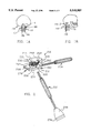
An example of such an implant is shown in FIGS. 1A and 1B. Specifically, a splint implant 100 is disposed to fix the relative disposition of respective vertebrae C1 and C2 at the base of a patient's occiput 102. Implant 100 includes respective parallel legs 106 and 108, connected by a generally U-shaped bridge 110. As best seen in FIG. 1A, respective legs 106 and 108 are disposed in parallel, extending along opposing sides of vertebrae C1 and C2 for a predetermined distance above and below the vertebrae. As best seen in FIG. 1B, bridge 110 is bent at an angle transverse to the plane of legs 106 and 108, coupling legs 106, while accommodating the patient's anatomical structure.
Historically, pre-bent splinting implants have been employed by surgeons. However, commercially available pre-bent implants are provided in specific sizes (e.g. small; medium; and large). Because the splinting implants do not typically meet morphological fit requirements, surgeons have generally reconfigured the bone to fit the implant. This process typically involves removing, e.g. grinding or cutting away, portions of the bone, and tends to be both time consuming and traumatic to the patient. Further, while the general configuration of a splinting implant for particular portions of the skeleton can be determined by x-ray and imaging techniques, in many instances it is desirable to confirm the desired configuration of the implant by visual inspection of the skeletal portions at issue. Accordingly, it is desirable that the surgeon be able to shape bendable metallic rods to form custom implants during surgery to meet the specific anatomical fit requirements of a patient.
Attempts have been made to form implants in the operating room during surgery by bending rods into the desired configuration. However, bending was effected employing pliers, vices, and hammers. While rod benders are, in general, known, the devices typically can bend the rod only to a single particular radius and are not shielded to protect against debris flying in the event that a rod breaks, but nonetheless tend to be relatively complex devices, including closed holes, cervices, and interstices, in which blood or tissue is often retained, and are difficult to disassemble for cleaning. Such devices are thus difficult to clean and sterilize e.g. by autoclaving, for use in the operating room.
Significantly, the prior techniques for custom bending of rod to form implants in the operating room, have tended to nick, scratch, gouge, or kink the surgical implant. Such marring tends to form stress risers, and to lead to early fatigue failure of the implant. Specifically, in situ, the splint implant is subject to relatively high stresses. While healthy bone typically replaces itself, thus accommodating wear from such stresses, that is not the case with a metal implant; normal stresses tend to fatigue the metal of the implant. Marring, such as any nicks, scratches, gouges, or the like in the implant, tends to produce very high stresses at the root of the mar, tending to make the implant more susceptible to bending and ultimate failure.
Fabrication of the implant in the operating room has also tended to involve a significant period of time, e.g. 20 to 25 minutes.
Accordingly, there is a need for an apparatus for custom forming of implants from metal rod in the operating room, quickly and economically, without marring the surface of the rod, and which is simple and readily disassemblable, and autoclavable to ensure proper sterilization.
The present invention provides a particularly advantageous apparatus for bending metal rod to form surgical implants in a sterile operating room environment, with minimal nicking and scratching of, and minimal transfer of foreign material to the rod. In accordance with one aspect of the invention, the bender includes a capstan, a primary mandrel, a gripping element, and a follower mandrel. The primary mandrel, which rotates with the capstan, includes at least one generally cylindrical portion with a guide channel formed in the periphery thereof.
The follower mandrel also includes at least one generally cylindrical portion with a guide channel formed in the periphery thereof. The follower guide channels are disposed in planar alignment with the corresponding guide channel of the primary mandrel to form bending channels therebetween.
The gripping member is mounted for rotation with said primary mandrel, and encloses a portion of the primary mandrel guide channel(s) to form a passageway(s) of predetermined configuration. The passageway(s) is configured such that when the primary mandrel is rotated to a predetermined position, said passageway is brought into general alignment with the corresponding bending channel, and the rod can be journaled through the passageway and through the bending channel without bending.
The capstan, primary mandrel, gripping member, and follower mandrel are formed of an autoclavable material with a predetermined hardness greater than the maximum hardness of the rod to be bent.
A preferred exemplary embodiment of the present invention will hereinafter be described in conjunction with the appended drawing, wherein like designations denote like elements, and:
FIG. 1A and B are schematic illustrations of an implant of the type formed by apparatus in accordance to present invention.
FIG. 2 is a pictorial illustration of a surgical rod bending device in accordance with the present invention;
FIG. 3 is a side view of the primary mandrel of the apparatus of FIG. 2;
FIG. 4 is a side view of the follower mandrel of the apparatus of FIG. 2;
FIG. 5A is a side view of the gripping element of the apparatus of FIG. 2;
FIG. 5B is a sectional view of the gripping element of the FIG. 5A;
FIG. 5C is a sectional view illustrating the initial engagement of a rod by the apparatus of FIG. 2;
FIGS. 6A, 6B and 6C are top, elevation and side views of the base plate of the apparatus of FIG. 2; and
FIG. 7 is a perspective view of the fulcrum bar of the apparatus of FIG. 2.
Referring now to FIG. 2, a surgical rod bender 200, in accordance with the present invention, comprises: a mandrel housing 202; a first lever arm, e.g. handle 204; a capstan 206; a primary mandrel 208; a rod gripping element, e.g. rod grip plate, 209; a follower mandrel 210; and a second, preferably removable, lever arm 212.
Mandrel housing 202 suitably comprises a base plate 214, a top plate 216, and an end plate (back) 218. Base plate 214 is suitably removably fastened to end plate 218. Top plate 216 is likewise removably connected to end plate 218. If desired, one of base plate 214 or top plate 216 can be formed integrally with end plate 218. Base plate 214 and top plate 216 are disposed generally in parallel planes, offset from each other by a predetermined distance, forming, together with end plate 218, a chamber, generally indicated as 221, open on three sides in the direction of the distal end of housing 202.
Respective axial pins 237 extending perpendicularly from plates 214 and 216, e.g. rotatably engaged in respect bores in plates 214 and 216, provide an axes of rotation for capstan 206 and primary mandrel 208. In the preferred embodiment, capstan 206, primary mandrel 208 and axial pins 237 rotatably engaged in respect bores in plates 214 and 216, are formed as an integral unit to simplify disassembly and reassembly, and sterilization.
Referring now to FIGS. 2, 5A and 5B, gripping member 209 is mounted for rotation with primary mandrel 208, effectively enclosing a portion of the guide channels 232, 234 and 236 of cylinders 226, 228 and 230, to form respective passageways 252, 254 and 256 (FIG. 5A). Passageways 252, 254 and 256 are suitably formed by boring holes through plate 209, at a predetermined angle with respect to the plate sides, i.e. with respect to a radius of mandrel 208. The angle and configuration of passageways 252, 254 and 256 are such that when primary mandrel 208 is rotated into a predetermined position, passageways 252, 254 and 256 are in alignment with the respective guide channels of the corresponding mandrel cylinders. As shown in FIG. 5C, rod 99 can be journaled through passageway 252, and through respective guide channels 232 and 244. In the preferred embodiment, passageways 252, 254 and 256 comprise bores of diameters slightly greater than the maximum rod diameter, disposed at an angle of approximately 53° relative to a radial line from primary mandrel 208.
In operation, primary mandrel is rotated to bring passageways 252, 254 and 256 into alignment with the respective bending channels formed between primary mandrel 208 and follower mandrel 210 (FIG. 5C). Rod 99 is then journaled through the passageway corresponding to the cylinder having the desired diameter of curvature, e.g. primary mandrel cylinder 232. The second lever arm 212 is engaged in one of the capstan holes 220. Lever arms 204 and 212 are then forced toward each other to rotate capstan 206, and hence primary mandrel 208 in, e.g. a counter-clockwise direction. As mandrel 208 is rotated, the passageway, e.g. 252, through which rod 99 is journaled, effectively engages rod 99, exerting angular force on rod 99. Passageway 252 forces rod 99, at the point of engagement, to be approximately tangent to the cylinder of primary mandrel 208. Follower mandrel 238 rolls against rod 99. Rod 99 thus follows the perimeter of primary mandrel cylinder 226, making rod 99 tend to rotate with primary mandrel 208. Follower mandrel 210, however, forces rod 99 to be tangent to mandrels 208 and 210 in the bending channel between the mandrels, causing rod 99 to bend into conformance with the periphery of guide channel 232.
If desired, a gauge 260 can be provided in top plate 216 to facilitate centering the U-shaped bridge to be formed at a particular point in the rod. A slot 262 is formed in top plate 216, preferably having an angled surface. Respective gauge lines 264 are formed corresponding to the respective cylinders of primary mandrel 208. The desired center point on the rod (typically, but not necessarily, the center of the rod, so that the implant legs are of equal length) is marked on the rod. When the rod is journaled through with a gripping passageway of gripping element 209 and the bending channel formed between mandrels 208 and 210, the mark aligned with the guide marking 264 corresponding to the particular cylinder through which the rod is journaled, the resultant bend will take place in the center of the rod.
Thus, a straight rod can be bent into a U shape. If desired, a mechanism can also be provided to effect bending of the U-shaped (arcuate) bridge of the implant to a predetermined transverse angle. Referring now to FIGS. 2, 6A, 65, 6C, 7, a radiused edge fulcrum plate (pinch plate) can be provided at the distal end of base plate 214. Specifically, a radiused edged fulcrum plate 266 is disposed for controlled axial movement relative to the end of base plate 214, to operate, in effect, as a vice to engage and tightly clamp the legs of the partially formed U-shaped implant rod, and act as a fulcrum against which the bridge portion of the implant can be bent. Respective notches 268, 270, 272, and 274 are formed in the distal edge of base plate 214. Notches 268, 270, 272 and 274 are configured to receive the legs of the U-shaped rod after it has been bent in the mandrel section, as can best be seen in FIGS. 2 and 6A. Notches 270, 272 and 274 are disposed at distances from notch 268 corresponding to the diameters of curvature of the respective cylinders of primary mandrel 208. A threaded axial bore 276 is provided to engage a threaded shaft of a tightening knob 278, which is journaled through a corresponding axial bore 280 in fulcrum plate 209. A guide pin (not shown) is journaled in an offset axial bore 282 in the distal end of base plate 214, and a corresponding axial bore 284, to maintain alignment. In addition, respective support shelves 286 and 288 (FIGS. 6A and 6C) are provided, extending axially from the distal edge of base plate 214. Corresponding notches 290 and 292 (FIG. 7) are formed in radiused fulcrum bar 209. The upper edge of fulcrum bar 209 manifests a predetermined radius corresponding to the desired angle to which the arcuate bridge is to be bent.
Lever arm 212 suitably includes a paddle shaped portion 294 at the end opposite to that which is received by capstan 206. A bridge 296 is provided on one side of paddle 294 in proximity to the panel end, forming a channel for receiving the U-shaped bridge of the partially formed implant. In operation, after the rod is bent into a U-shape using mandrels 208 and 210, the legs of the U are inserted downwardly into notch 268, and corresponding notch 270, 272, or 274. The legs are then tightly clamped by by fulcrum bar 209 by tightening knob 278. Notches 290 and 292 ride on shelves 286 and 288. The position of the legs adjacent to radiused edge 279 corresponds to the position at which the bend is desired. Such position is dictated by the anatomy of the patient, and is determined by the surgeon, with the aid of pre-operation x-rays and imaging, and visual inspection during the operation. Lever arm paddle 294 is disposed to engage the bridge of the U-shaped rod, with the rod received between the surface of paddle 294 and bridge 296. Lever arm 212 is then cantilevered away from mandrel housing 202 (in a counter-clockwise direction) to cause the legs of the U-shaped rod to bend to conformity with the radiused edge of fulcrum bar 209.
If desired, paddle 294 can also include gauge markings corresponding to the respective diameters of curvature provided by the respective cylinders of primary mandrel 208, for use by the surgeon in gauging the appropriate sizing.
It should be appreciated that surgical rod bender 200 is particularly advantageous in a number of respects. The device provides uniform and consistent implants in a matter of a few moments. Further, the process inflicts relatively few mars on the surface of the rod during the formation process. The rotation of follower mandrel 210, and relatively large engaging surface of gripping rod passageway 252 tend to minimize scratches, nicks, and other marring. Thus, the potential of high stress in the bent rod, and potential failure of the rod either during the bending process or after the device has been implanted, is minimized. Moreover, the disposition of mandrels 208 and 210 within the interior of housing 202, effectively shrouds the area where bending is taking place. Thus, in the event of a fracture of the rod during bending, the combination of the box-like shape of the housing, and the action of grip plate 209 to hold onto metal fragments minimize the risk of injury due to flying metal fragments.
In addition, the device is readily disassemblable and easily sterilized. The device can be disassembled by removal of two bolts affixing the proximal end of base plate 214 to end plate 218. The axial pins of mandrels 208 and 210 are received in respective apertures in plates 214 and 216. Removal of base plate 214, frees mandrels 208 and 210 for removal. Alignment during the assembly presents no problem; the respective mandrel pins are simply reinserted in the respective apertures and base plate 214 reaffixed to end plate 218. In addition, sets of interchangeable mandrels having various diameters, and combination of diameters can be employed to provide a wide range of curvature diameters. Likewise, various interchangeable fulcrum bars 209 can be employed, each having a different radius to control the bend angle of the bridge. Further, the device avoids transfer of foreign particles to the implant and noted above. Further, there are no closed holes or features of the device that cannot be easily cleaned, so that blood and tissue debris will not be retained on the device.
It will be understood that the above description is of preferred exemplary embodiments of the present invention, and the invention is not limited to the specific form shown. Modifications may be made in the design and arrangement of the elements within the scope of the invention, as expressed in the claims.
Claims (19)
1. Apparatus for bending a metal rod with a predetermined maximum hardness characteristic to form a surgical implant in a sterile operating room environment, with minimal nicking and scratching of, and minimal transfer of foreign material to, the rod, the apparatus comprising:
a mandrel housing including first and second generally parallel housing plates having proximal and distal ends, and a transversely disposed end piece removably connecting the plates:
a first lever arm extending rearwardly from the mandrel housing in a plane generally parallel to the planes of the plates;
a capstan rotatably disposed between the plates,
a second lever arm adapted to engage the capstan to facilitate rotation thereof;
the capstan comprising a cylinder of predetermined radius and height, including a plurality of radially disposed bores of a predetermined diameter, the capstan bores being adapted to receive a first end of the second lever arm and disposed in the same plane as the first lever arm, such that the first and second lever arms can be moved toward each other during the bending process without generating any spurious torques;
a primary mandrel axially aligned with the capstan and fixed thereto for rotation therewith, the primary mandrel having at least one generally cylindrical portion with a guide channel formed in the circumferential surface thereof,
a follower mandrel, having at least one generally cylindrical portion with a guide channel formed in the circumferential surface thereof, the follower mandrel being rotatably disposed in the mandrel housing and axially offset from the first mandrel by a predetermined distance generally corresponding to the diameter of the rod, with the guide channel of the follower mandrel being in planar alignment with the guide channel of the primary mandrel to form a bending channel therebetween;
a gripping member mounted for rotation with the primary mandrel, the gripping member enclosing a portion of the guide channel of the primary mandrel cylindrical portion to thereby form an enclosed passageway of predetermined configuration;
the passageway being configured such that when the primary mandrel is rotated to a predetermined starting position, the passageway is brought into general alignment with the bending channel, and the rod can be journaled through the passageway and into the bending channel;
the housing, first lever arm, second lever arm, capstan, primary mandrel, gripping member and follower mandrel each being formed of an autoclavable material with a predetermined hardness at least equal to the maximum hardness of the rod;
rotation of the primary mandrel, with a rod journaled through the gripping member passageway and bending channel, causing the gripping member passageway to engage the rod, and pull the rod through the bending channel, to bend the rod into conformance with the primary mandrel cylindrical portion.
2. The apparatus of claim 1 wherein the capstan includes four radially disposed bores.
3. The apparatus of claim 1 wherein:
the primary mandrel comprises a predetermined number of stacked cylinders of decreasing diameter;
the follower mandrel comprises a predetermined number of corresponding stacked cylinders of increasing diameter; and
each of the cylinders includes:
a respective peripheral guide channel, with the peripheral guide channels of corresponding cylinders in planar alignment to form respective bending channels therebetween; and
a respective gripping member, mounted for rotation with the primary mandrel, which encloses a portion of the guide channels of the primary mandrel cylinders, to form respective passageways of predetermined configuration.
4. The apparatus of claim 3 wherein the difference in diameters of the respective adjacent cylinders of the follower mandrel correspond to the difference in diameters of the adjacent cylinders of the primary mandrel.
5. The apparatus of claim 3 wherein the primary mandrel comprises three stacked cylinders.
6. The apparatus of claim 5 wherein the diameters of the primary mandrel cylinders are 11/4 inch, 1 inch, and 3/4 of an inch.
7. The apparatus of claim 3 wherein the gripping member comprises a plate with through holes disposed at a predetermined angle with respect to a radius of the primary mandrel, such that when the primary mandrel is in a predetermined position, the gripping member passageways are in alignment with the respective bending channels.
8. The apparatus of claim 7 wherein the gripping member passageways comprise bores of diameters slightly greater than the maximum rod diameter to be bent, disposed at an angle of approximately 53° relative to a radial line from the primary mandrel.
9. The apparatus of claim 1 wherein the gripping member comprises a plate with a through hole disposed at a predetermined angle with respect to a radius of the primary mandrel, such that when the primary mandrel is in a predetermined position, the gripping member passageways are in alignment with the bending channels.
10. The apparatus of claim 9 wherein the gripping member passageway comprises a bore of a diameter slightly greater than the maximum rod diameter to be bent, disposed at an angle of approximately 53° relative to a radial line from the primary mandrel.
11. The apparatus of claim 1 wherein the follower mandrel is disposed inboard of the primary mandrel to facilitate rotation of the capstan through action of the second lever arm.
12. The apparatus of claim 1 wherein the mandrels are harder, by at least 20%, than the maximum hardness of the rods to be bent.
13. The apparatus of claim 1 wherein the mandrels are harder, by at least 30%, than the maximum hardness of the rods to be bent.
14. The apparatus of claim 1 wherein the mandrels are harder, by at least 40%, than the maximum hardness of the rods to be bent.
15. The apparatus of claim 2 wherein the mandrels and gripping member are formed of 17-4 hardenable stainless steel hardened to approximately 40 to 45 Rockwell C.
16. The apparatus of claim 1 further including a gauge provided in the first housing plate to facilitate centering a U-shaped bridge to be formed at a particular point in the rod.
17. The apparatus of claim 16 wherein the gauge comprises a slot formed in the first plate and respective gauge lines corresponding to each cylinder of the primary mandrel.
18. The apparatus of claim 1 further including a radiused edge fulcrum plate disposed for controlled axial movement relative to the distal end of the housing second plate, for engaging rods placed between the fulcrum plate and the end of the housing second plate, and acting as a fulcrum against which the rod can be bent.
19. The apparatus of claim 18 wherein the second lever arm includes:
a paddle shaped portion at a second end opposite to the first end which is received by the capstan; and
a bridge is provided on one side of the paddle portion in proximity to a distal end thereof, forming a channel for receiving a rod.
Priority Applications (3)
| Application Number | Priority Date | Filing Date | Title |
|---|---|---|---|
| US08/242,169 US5548985A (en) | 1994-05-13 | 1994-05-13 | Rod bender for forming surgical implants in the operating room |
| PCT/US1995/006019 WO1995031299A1 (en) | 1994-05-13 | 1995-05-15 | Rod bender for forming surgical implants |
| AU25497/95A AU2549795A (en) | 1994-05-13 | 1995-05-15 | Rod bender for forming surgical implants |
Applications Claiming Priority (1)
| Application Number | Priority Date | Filing Date | Title |
|---|---|---|---|
| US08/242,169 US5548985A (en) | 1994-05-13 | 1994-05-13 | Rod bender for forming surgical implants in the operating room |
Publications (1)
| Publication Number | Publication Date |
|---|---|
| US5548985A true US5548985A (en) | 1996-08-27 |
Family
ID=22913726
Family Applications (1)
| Application Number | Title | Priority Date | Filing Date |
|---|---|---|---|
| US08/242,169 Expired - Fee Related US5548985A (en) | 1994-05-13 | 1994-05-13 | Rod bender for forming surgical implants in the operating room |
Country Status (3)
| Country | Link |
|---|---|
| US (1) | US5548985A (en) |
| AU (1) | AU2549795A (en) |
| WO (1) | WO1995031299A1 (en) |
Cited By (16)
| Publication number | Priority date | Publication date | Assignee | Title |
|---|---|---|---|---|
| US5727419A (en) * | 1996-09-26 | 1998-03-17 | Applied Power Inc. | Tube bender handle |
| US6644087B1 (en) | 2002-07-26 | 2003-11-11 | Third Millennium Engineering, Llc | Rod bender for bending surgical rods |
| US20040144149A1 (en) * | 2002-05-02 | 2004-07-29 | Walter Strippgen | Non-marring spinal rod curving instrument and method for using same |
| US7488331B2 (en) | 2005-05-23 | 2009-02-10 | Custon Spine, Inc. | Orthopedic implant bender |
| US20100268119A1 (en) * | 2009-04-15 | 2010-10-21 | Warsaw Orthopedic, Inc., An Indiana Corporation | Integrated feedback for in-situ surgical device |
| US8235998B2 (en) | 2009-08-17 | 2012-08-07 | Warsaw Orthopedic, Inc. | Instruments and methods for in situ bending of an elongate spinal implant |
| US8298242B2 (en) | 2010-04-30 | 2012-10-30 | Warsaw Orthopedic, Inc. | Systems, devices and methods for bending an elongate member |
| US8607603B2 (en) | 2010-04-30 | 2013-12-17 | Warsaw Orthopedic, Inc. | Systems, devices and methods for multi-dimensional bending of an elongate member |
| US9003859B2 (en) | 2011-04-01 | 2015-04-14 | University of Alaska Anchorage | Bending instrument and methods of using same |
| US9421596B2 (en) | 2014-04-16 | 2016-08-23 | University of Alaska Anchorage | Bending instrument and methods of using same |
| US9636181B2 (en) | 2008-04-04 | 2017-05-02 | Nuvasive, Inc. | Systems, devices, and methods for designing and forming a surgical implant |
| US9848922B2 (en) | 2013-10-09 | 2017-12-26 | Nuvasive, Inc. | Systems and methods for performing spine surgery |
| US9913669B1 (en) | 2014-10-17 | 2018-03-13 | Nuvasive, Inc. | Systems and methods for performing spine surgery |
| US10610277B2 (en) | 2016-03-31 | 2020-04-07 | K2M, Inc. | Surgical rod bender |
| US11207132B2 (en) | 2012-03-12 | 2021-12-28 | Nuvasive, Inc. | Systems and methods for performing spinal surgery |
| US11576727B2 (en) | 2016-03-02 | 2023-02-14 | Nuvasive, Inc. | Systems and methods for spinal correction surgical planning |
Families Citing this family (2)
| Publication number | Priority date | Publication date | Assignee | Title |
|---|---|---|---|---|
| AU783476B2 (en) * | 2000-11-06 | 2005-11-03 | Rightway Industry Co. Ltd | Hydraulic forming machine for metal tubes |
| CN103143600A (en) * | 2012-08-03 | 2013-06-12 | 苏州艾隆科技股份有限公司 | Aluminum section bending clamp and aluminum section bending method |
Citations (4)
| Publication number | Priority date | Publication date | Assignee | Title |
|---|---|---|---|---|
| FR1132047A (en) * | 1955-05-25 | 1957-03-04 | Improvements made to bending machines | |
| GB2206069A (en) * | 1987-06-16 | 1988-12-29 | William Samuel Rutherford | Pipe bending apparatus |
| US4926672A (en) * | 1989-05-03 | 1990-05-22 | Lidseen Of North Carolina, Inc. | Pipe bender |
| US5148695A (en) * | 1991-11-21 | 1992-09-22 | Ellis Harry S | Adjustable pipe and tubing bender |
Family Cites Families (1)
| Publication number | Priority date | Publication date | Assignee | Title |
|---|---|---|---|---|
| US2695538A (en) * | 1951-03-19 | 1954-11-30 | Tal Bender Inc | Ratchet and pawl actuated lightweight tube benders |
-
1994
- 1994-05-13 US US08/242,169 patent/US5548985A/en not_active Expired - Fee Related
-
1995
- 1995-05-15 AU AU25497/95A patent/AU2549795A/en not_active Abandoned
- 1995-05-15 WO PCT/US1995/006019 patent/WO1995031299A1/en active Application Filing
Patent Citations (4)
| Publication number | Priority date | Publication date | Assignee | Title |
|---|---|---|---|---|
| FR1132047A (en) * | 1955-05-25 | 1957-03-04 | Improvements made to bending machines | |
| GB2206069A (en) * | 1987-06-16 | 1988-12-29 | William Samuel Rutherford | Pipe bending apparatus |
| US4926672A (en) * | 1989-05-03 | 1990-05-22 | Lidseen Of North Carolina, Inc. | Pipe bender |
| US5148695A (en) * | 1991-11-21 | 1992-09-22 | Ellis Harry S | Adjustable pipe and tubing bender |
Cited By (23)
| Publication number | Priority date | Publication date | Assignee | Title |
|---|---|---|---|---|
| US5727419A (en) * | 1996-09-26 | 1998-03-17 | Applied Power Inc. | Tube bender handle |
| US20040144149A1 (en) * | 2002-05-02 | 2004-07-29 | Walter Strippgen | Non-marring spinal rod curving instrument and method for using same |
| US6644087B1 (en) | 2002-07-26 | 2003-11-11 | Third Millennium Engineering, Llc | Rod bender for bending surgical rods |
| US7488331B2 (en) | 2005-05-23 | 2009-02-10 | Custon Spine, Inc. | Orthopedic implant bender |
| US10500630B2 (en) | 2008-04-04 | 2019-12-10 | Nuvasive, Inc. | Systems, devices, and methods for designing and forming a surgical implant |
| US9636181B2 (en) | 2008-04-04 | 2017-05-02 | Nuvasive, Inc. | Systems, devices, and methods for designing and forming a surgical implant |
| US11453041B2 (en) | 2008-04-04 | 2022-09-27 | Nuvasive, Inc | Systems, devices, and methods for designing and forming a surgical implant |
| US20100268119A1 (en) * | 2009-04-15 | 2010-10-21 | Warsaw Orthopedic, Inc., An Indiana Corporation | Integrated feedback for in-situ surgical device |
| US8235998B2 (en) | 2009-08-17 | 2012-08-07 | Warsaw Orthopedic, Inc. | Instruments and methods for in situ bending of an elongate spinal implant |
| US8298242B2 (en) | 2010-04-30 | 2012-10-30 | Warsaw Orthopedic, Inc. | Systems, devices and methods for bending an elongate member |
| US8607603B2 (en) | 2010-04-30 | 2013-12-17 | Warsaw Orthopedic, Inc. | Systems, devices and methods for multi-dimensional bending of an elongate member |
| US9003859B2 (en) | 2011-04-01 | 2015-04-14 | University of Alaska Anchorage | Bending instrument and methods of using same |
| US11207132B2 (en) | 2012-03-12 | 2021-12-28 | Nuvasive, Inc. | Systems and methods for performing spinal surgery |
| US9848922B2 (en) | 2013-10-09 | 2017-12-26 | Nuvasive, Inc. | Systems and methods for performing spine surgery |
| US9421596B2 (en) | 2014-04-16 | 2016-08-23 | University of Alaska Anchorage | Bending instrument and methods of using same |
| US10485589B2 (en) | 2014-10-17 | 2019-11-26 | Nuvasive, Inc. | Systems and methods for performing spine surgery |
| US10433893B1 (en) | 2014-10-17 | 2019-10-08 | Nuvasive, Inc. | Systems and methods for performing spine surgery |
| US11213326B2 (en) | 2014-10-17 | 2022-01-04 | Nuvasive, Inc. | Systems and methods for performing spine surgery |
| US9913669B1 (en) | 2014-10-17 | 2018-03-13 | Nuvasive, Inc. | Systems and methods for performing spine surgery |
| US11576727B2 (en) | 2016-03-02 | 2023-02-14 | Nuvasive, Inc. | Systems and methods for spinal correction surgical planning |
| US11903655B2 (en) | 2016-03-02 | 2024-02-20 | Nuvasive Inc. | Systems and methods for spinal correction surgical planning |
| US10610277B2 (en) | 2016-03-31 | 2020-04-07 | K2M, Inc. | Surgical rod bender |
| US11737803B2 (en) | 2016-03-31 | 2023-08-29 | K2M, Inc. | Surgical rod bender |
Also Published As
| Publication number | Publication date |
|---|---|
| WO1995031299A1 (en) | 1995-11-23 |
| AU2549795A (en) | 1995-12-05 |
Similar Documents
| Publication | Publication Date | Title |
|---|---|---|
| US5548985A (en) | Rod bender for forming surgical implants in the operating room | |
| US11903621B2 (en) | Rod reduction device and method of use | |
| US10433893B1 (en) | Systems and methods for performing spine surgery | |
| US8167908B2 (en) | Polyaxial transverse connector | |
| US9468476B2 (en) | System and method for performing spinal surgery | |
| US5389099A (en) | Keyhole rod bender | |
| US5385565A (en) | Tool and method for derotating scoliotic spine | |
| US8668699B2 (en) | Multi-function orthopedic instrument | |
| EP0689402B1 (en) | Apparatus for the external setting of fractures | |
| US8221426B2 (en) | Methods and devices for deformity correction | |
| JP4176009B2 (en) | Surgical rod adjustment instrument and method | |
| JP4633622B2 (en) | Spine stabilization system | |
| US5514136A (en) | Surgical instrument for driving and rotating a long bone prosthesis | |
| US8454665B2 (en) | Multi-purpose bone plate system | |
| US20100111631A1 (en) | Tool for Finishing the Ends of Surgical Rods and Methods of Use | |
| US10238439B2 (en) | Anterior spinal bone plate holding system and method | |
| US20040144149A1 (en) | Non-marring spinal rod curving instrument and method for using same | |
| US20090259262A1 (en) | Surgical tool | |
| JP2001507973A (en) | Bone fixation pin with rotary cutting tip | |
| CA2803178A1 (en) | Spinal stabilization system | |
| JP2019150562A (en) | Compressor/distractor | |
| WO2015112923A1 (en) | Retraction devices and methods of its use and manufacture | |
| EP2881054A1 (en) | Spinal stabilization system including shaped spinal rod | |
| US20030205075A1 (en) | Spinal rod curving instrument and method for using same | |
| JP2022505436A (en) | Orthopedic rod vendor |
Legal Events
| Date | Code | Title | Description |
|---|---|---|---|
| FPAY | Fee payment |
Year of fee payment: 4 |
|
| REMI | Maintenance fee reminder mailed | ||
| LAPS | Lapse for failure to pay maintenance fees | ||
| FP | Lapsed due to failure to pay maintenance fee |
Effective date: 20040827 |
|
| STCH | Information on status: patent discontinuation |
Free format text: PATENT EXPIRED DUE TO NONPAYMENT OF MAINTENANCE FEES UNDER 37 CFR 1.362 |