US5548394A - Scanning fingerprint reading - Google Patents
Scanning fingerprint reading Download PDFInfo
- Publication number
- US5548394A US5548394A US08/404,931 US40493195A US5548394A US 5548394 A US5548394 A US 5548394A US 40493195 A US40493195 A US 40493195A US 5548394 A US5548394 A US 5548394A
- Authority
- US
- United States
- Prior art keywords
- scan
- image
- mirror
- optical
- sensors
- Prior art date
- Legal status (The legal status is an assumption and is not a legal conclusion. Google has not performed a legal analysis and makes no representation as to the accuracy of the status listed.)
- Expired - Lifetime
Links
Images


Classifications
-
- G—PHYSICS
- G06—COMPUTING; CALCULATING OR COUNTING
- G06V—IMAGE OR VIDEO RECOGNITION OR UNDERSTANDING
- G06V40/00—Recognition of biometric, human-related or animal-related patterns in image or video data
- G06V40/10—Human or animal bodies, e.g. vehicle occupants or pedestrians; Body parts, e.g. hands
- G06V40/12—Fingerprints or palmprints
- G06V40/13—Sensors therefor
- G06V40/1324—Sensors therefor by using geometrical optics, e.g. using prisms
-
- G—PHYSICS
- G06—COMPUTING; CALCULATING OR COUNTING
- G06V—IMAGE OR VIDEO RECOGNITION OR UNDERSTANDING
- G06V40/00—Recognition of biometric, human-related or animal-related patterns in image or video data
- G06V40/10—Human or animal bodies, e.g. vehicle occupants or pedestrians; Body parts, e.g. hands
- G06V40/12—Fingerprints or palmprints
- G06V40/1335—Combining adjacent partial images (e.g. slices) to create a composite input or reference pattern; Tracking a sweeping finger movement
Definitions
- the present invention relates to the reading of fingerprints, and more particularly concerns methods and apparatus for viewing a finger and providing a body of output data that accurately and precisely defines a fingerprint.
- Fingerprint identification is becoming increasingly automated, and as advantages of automatic fingerprint identification systems become more apparent through widespread use, automated fingerprint identification systems are becoming more common and more widely used. Many of such automated fingerprint identification systems input an electronic representation of an unknown fingerprint for use in selection of one or more matching prints from a massive body of stored electronic representations of many fingerprints. Yet, despite the extent and sophistication of automated fingerprint matching, fingerprints still are captured and recorded by old and conventional procedures utilizing ink, ink pad, and roller to provide an inked impression which is scanned to form a digital electronic representation for storage or comparison. These conventional procedures are inconvenient, slow, and, in many cases, inefficient. They frequently fail to record adequate definition of certain details, singularities and minutiae that are employed in fingerprint identification and matching processes.
- a fingerprint reader includes an imaging system that produces an optical image of a fingerprint, a scanning mirror, a linear array of sensors, and a feedback control system for coordinating the capture of the fingerprint image by the sensor array with the relative motion of a rolling finger, via dynamic positioning of the scan mirror. Because the object plane is tilted, the image plane is also tilted so as to keep the image in sharp focus. Resultant keystone distortion is eliminated by an optical system that is telecentric in both object space and image space.
- a scanning mirror employed to scan the optical image across the linear array of sensors is interposed between a scan lens and a focus lens having a common focal point at which the mirror is positioned. For reading out a roll print there is generated a finger position signal indicative of position of a finger in the object plane, and a controller is provided to control the angular position of the scan mirror in response to the indicated finger position.
- the optical system has an anamorphic magnification
- the scan rate of the scan mirror is controlled to compensate for the anamorphic magnification, and to make the effective magnification of the system equal in two mutually orthogonal directions.
- FIG. 1 illustrates an imaging prism and an illumination system therefor that form a total internal reflection imaging arrangement for a fingerprint reader embodying principles of the present invention
- FIG. 2 is a schematic illustration of a fingerprint reading system of the present invention
- FIG. 3 illustrates the arrangement of a linear array print camera with respect to a fingerprint image
- FIG. 4 illustrates a signal obtained from a linear array camera used to detect position of a rolling finger
- FIG. 5 illustrates the relative orientation of a linear array camera for detecting finger position and an image of a single finger
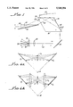
- FIGS. 6a and 6b illustrate certain imaging conditions for imaging a tilted object plane.
- the system of the present apparatus is based upon total internal reflection from a prism that forms a platen against which a finger or a group of fingers are pressed for the reading of fingerprints.
- the system provides an electrical output that is an accurate representation of a fingerprint of one or more fingers pressed against the platen.
- a rhomboidal prism 10 has parallel end faces 12 and 14, an input face 16, a reflective face 18, a platen face 20 parallel to input face 16, and an output face 22 parallel to reflective face 18.
- the prism is a 60° or 65° BK-7 glass prism.
- the angle between sides 16 and 18 and 20 and 22 is preferably 65°.
- the several surfaces of the prism are rectangular, with the platen or uppermost face 20 having a dimension in the order of 2 by 31/4 inches, for example.
- the prism is formed of a BK-7 glass, it has a critical angle of 41.315° when the medium at the exterior of the prism is air, and a critical angle of 61.65° when the external medium is water.
- the critical angle is 72.0°. Accordingly, there is total internal reflection from the upper face or platen 20 when air or water is in contact with the platen 20, but this internal reflection is defeated by contact with ridges of a finger pressed against the platen 20.
- a light source 24 which may comprise a circular array of light emitting diodes (although a linear array may be used), directs the light from all diodes at a common spot 25 on an elliptical beam spreading diffuser 26 which spreads the beam by about five degrees in a vertical direction (as viewed in FIG. 1), and by about 10 degrees in a horizontal direction (perpendicular to the plane of the paper).
- the diffuser sends a spreading beam through a lens 28 that directs an illumination beam 30 of essentially parallel rays at an input mirror 32 that is positioned at or about 45° to the axis of the beam 30.
- the illumination light is reflected from input mirror 32 at nearly right angles to the input face 16 of the prism 10.
- This light is reflected internally within the prism 10 from the reflection surface 18, which is silvered on its exterior face to ensure full reflection, and thence reflected to the internal surface of platen 20.
- the light impinges on platen 20 at an angle of incidence equal to or greater than the critical angle of the glass/air or glass/water interface (in the absence of a finger pressed against the platen 20).
- This beam contains optical information which, when focused, provides a reflection map of the glass/skin interface, from which fingerprint ridge definition is derived.
- a finger or group of fingers such as indicated at 39 in FIG. 1, placed on or pressed against the platen 20 of the prism, defines spatially the total internal reflection profile of light rays at the internal face of the platen.
- the prism/air interface provides a critical angle for total internal reflection as described.
- the total internal reflection of the prism is defeated so that light from those points at which the finger ridges touch the platen is not totally internally reflected but, instead, most of the light passes out of the prism through the face 20, and is absorbed by the finger or fingers.
- an output light beam 37 passed through the output face 22 of the prism is a pattern of dark (low intensity light) and light (high intensity light), where the dark represents the fingerprint pattern. This is a direct analog of an inked fingerprint.
- Optical axis 38 of output light beam 37 is coincident with the optical axis of a multi-element scan lens 40 (FIG. 2) to which the image is directed from the folding mirror 36.
- a multi-element scan lens 40 (FIG. 2) to which the image is directed from the folding mirror 36.
- Light from the scan lens 40 is directed to a turning mirror 44 and thence through a first beam splitter 46 to a scan mirror 48.
- the scan mirror is mounted for rotation about an axis 50 lying in the plane of the reflective surface of the mirror and extending perpendicular to the plane of the paper, as viewed in FIG. 2.
- the mirror position is controlled by a scan mirror actuator and control system 52, which is capable of driving the mirror at a constant rotational speed or to a desired angular position under control of a position input command to the controller 52, as will be more particularly described below.
- Print camera 60 comprises a fixedly positioned linear array charge coupled device (CCD) whose sensors extend in a direction that may be termed a "cross scan direction", namely a direction perpendicular to the direction of scan produced by the rotation of scan mirror 50.
- CCD linear array charge coupled device
- the print camera 60 is part of the first of three optical paths in this system.
- the first or print scan path includes the prism 10, lens 40, scan mirror 48, lens 56 and the print camera 60.
- a second optical path is a live view monitor path to enable live visual monitoring of the print capture process.
- a third optical path is a roll print tracking path that includes a second linear array CCD for generating a position signal that indicates a centroidal position for a single finger moving across the prism platen. Components of the print scan path have been described above. The live monitor and roll print tracking paths will be described in detail below.
- the drawing shows a top view of the platen 20 and indicates the scan as taking place in the Y direction, as indicated by arrow 62.
- a cross scan direction, indicated by arrow 64 is perpendicular to the scan direction Y and extends in an X direction from left to right of the drawing as viewed in FIG. 2.
- a finger or fingers are placed on the platen 20 with their longitudinal extent parallel to the cross scan or X direction (see FIG. 3), and the system is arranged by means including rotation of the scanning mirror to effectively move the image (at the print camera 60) from one side to the other of the platen 20 (vertically as viewed in FIG. 2) in the direction of scan arrow 62.
- the image of this platen is schematically depicted at 66 in FIG. 3, showing the Y direction arrow 62 and X direction arrow 64.
- a "slap" print or flat hand print of all four fingers is illustrated in dotted lines at 68 in FIG. 3 to indicate orientation of the fingers relative to the platen image.
- a linear array CCD 70 constituting the print camera. This linear array extends in the cross scan or X direction so that as the entire image 66 is caused to scan (by rotation of the scan mirror 50) in the Y direction, the entire image will move across the CCD in the Y direction (vertically as seen in FIG. 3).
- Circuit 72 contains an analog voltage storage cell for each of the sensors of the CCD array. Contents of the analog voltage storage cells are fed to an analog shifting circuit 74 that shifts the contents of each analog cell to its adjacent cell and thence out to an analog to digital converter 76 from the output of which, on a line 78, appears a serial bit stream of digital data that defines a digitized version, in two dimensions, of all the pixels of the fingerprint.
- the digitized output defines pixels that are positioned adjacent to each other on the platen at five hundred per inch, in both X and Y.
- the mirror scan rate causes the full image of platen 20 to traverse the linear array of print camera 60 with a duration on the order of a second (about one full traverse per second).
- this scan rate is adjusted to control effective magnification in the cross scan (X) direction, as will be described below.
- the live view monitor path is the second optical path.
- a portion of the image light from scan lens 40 is reflected from beam splitter 46 through a positive cylindrical lens 80, through a second beam splitter 82, and thence to a monitoring video camera 84, which may take the form of a two-dimensional CCD that provides an input to a CRT monitor 84.
- the two-dimensional CCD array and monitor 84 provide a visual display of the object on platen 20 at all times so that an operator can determine if all four fingers are properly placed on the platen or that a single finger is properly rolled across the platen.
- Fingerprints are taken in two general types, a full finger scan, often termed a "slap print", in which all four fingers are placed together on the platen, and then, while in a fixed position on the platen are read together as a single unit by the reading apparatus. The apparatus and operation described to this point reads such a "slap print”.
- Fingerprints are also provided as prints of individual fingers, often termed "roll prints” because these prints are taken of a single finger at a time, with the finger caused to roll across the platen surface about the longitudinal axis of the finger.
- roll prints As the single finger is rolled across the platen, at any instant there is a relatively narrow line of contact, extending longitudinally of the finger, between the finger and the platen. This line of contact moves across the platen (in Y direction) as the finger rolls.
- the scanning mirror position is controlled so that the particular portion of the image that contains the line of contact of the finger with the platen (at such Y position) is effectively aligned with the line of the CCD 70 of the print camera.
- an estimate of the Y position of the line of contact of the finger during a rolling print operation is obtained by reflecting part of the image beam from beam splitter 46 and lens 80 to the second beam splitter 82, from which it is reflected through a lens 90 to a roll camera 92.
- Roll camera 92 includes a second fixedly positioned linear array CCD sensor indicated at 94. As illustrated in FIG.
- the second linear CCD array 94 is oriented across the image 96 in the Y direction. That is, the array 94 of the roll camera is oriented in the scan direction and transverse to the longitudinal axis 98 of a finger 100 of which a roll print is being made.
- X direction arrow 64 and Y direction arrow 62 are also shown in FIG. 5 to indicate orientation of the finger image and line CCD 94 at the roll camera 92.
- This optical signal for one typical instantaneous position of the moving finger has the general form of a curve 104 shown in FIG. 4.
- Signal 104 varies in the Y direction, e.g., transverse to the length of the finger.
- the optical signal into the roll camera includes high intensity lateral portions 106,108 representing the total internal reflection at the glass/air interface, e.g., where the finger does not contact the platen.
- a central portion of this optical signal, indicated at 110 effectively provides a low intensity light area having a number of small variations 112 indicating print ridges.
- the depressed or low intensity light area 110 effectively extends between points 114 and 116 of this optical signal.
- the optical signal is effectively filtered, as by defocusing the optical signal on the line camera 94, to provide a signal that is generally indicated by the dotted line 120 in FIG. 5.
- This signal represents the voltage level of charges in those of the several CCD sensors of the linear roll camera that are at the image of the finger position at a given time during the finger rolling motion.
- the roll camera provides an output from the linear array CCD to a smoothing and processing circuit 122 (FIG. 2) that yields on an output line 124 an electrical position estimate signal having a magnitude that represents the Y position of the longitudinal axis of the finger, such as finger axis 98 of FIG. 5, during the course of its rolling across the prism platen.
- This position estimate signal is fed via line 124 as a position control input to the scan mirror actuator and control circuit 52 to thereby control the angular position of the scan mirror.
- the mirror is moved about its axis to an orientation that directs the image of platen 20 (including a finger pressed thereagainst during a roll print operation) so that the image of the line of contact of this finger during its rolling action is always aligned with the linear array 70 of the print camera 60.
- a significant feature of the described system is the fact that the print scan path, from the prism platen to the print camera 60, produces an image on the linear CCD array of the print camera that is free of keystone distortions. It is free of distortion in both the scan and cross scan image direction.
- the object plane (the platen surface) is inclined at 65° (with a 65° prism) to the optical axis. Inclination of the object plane requires that the image plane be tilted so that its projection intercepts the crossing of the projected object plane with the lens principal plane in order to keep the image in sharp focus.
- the Scheimpflug imaging condition is illustrated schematically in FIG.
- FIG. 6a for a 1:1 afocal relay employing a lens L o for providing an image on an oblique image plane P i of an object on an oblique object plane P o .
- Projections (extensions) of the image and object plane intercept each other and the lens principal plane at a common point (actually a line) A.
- FIG. 6b Use of the same set up with an afocal 1:1 relay is shown in FIG. 6b with tilted image and object planes P i1 and P o , lenses L 1 and L 2 , and a common pupil or aperture stop S between them.
- FIG. 6b Use of the same set up with an afocal 1:1 relay is shown in FIG. 6b with tilted image and object planes P i1 and P o , lenses L 1 and L 2 , and a common pupil or aperture stop S between them.
- FIGS. 1-5 The system described above and shown in FIGS. 1-5 is basically analogous to the arrangement shown in FIG. 6b, where lens L 1 corresponds to the focus lens 56, lens L 2 to the scan lens 40, object plan P o to platen 20, image plane P i to the surface of print camera 60, and pupil S to scan mirror 48, with the plane of the pupil S intersecting at a common point (plane) with the planes of the image and object surfaces.
- the tilt of the image plane in an exemplary system is 65°, where the object plane is also tilted at 65 degrees.
- the tilt of both object plane and image plane in the drawing of FIG. 2 (analogous to the arrangement of FIG. 6b) is at an angle to the plane of the paper, tilting about an axis extending from the top to bottom of the paper.
- the tilt axis lies in a plane parallel to the plane of the paper and perpendicular to the optical axis.
- the Scheimpflug imaging condition obtains sharp focus of a tilted object plane, but leaves a keystone distortion, which is actually a non-uniform magnification in scan and cross scan planes.
- the usual Scheimpflug arrangement with a tilted object plane causes image magnification to vary from top to bottom of the image and also from left to right so that, for example, a square object is imaged as a trapezoid.
- This undesirable condition is avoided in the present system by establishing a concurrent condition of telecentricity in both object and image space. This dual telecentricity condition maintains the magnification uniform and unvarying in both scan and cross scan directions to avoid keystone distortion.
- magnification is 0.53, whereas in the cross scan direction the magnification is one-half of that or 0.265.
- the exit pupil is at infinity and exiting rays are parallel. This is known as a telecentric condition.
- the scan mirror 48 is a common pupil for both the focus lens and the scan lens.
- the scan mirror 48 is an exit pupil for the scan lens 40, being positioned at a distance from the scan lens equal to its focal length (about 280 millimeters in the embodiment described herein).
- the mirror is also an entrance pupil for the focus lens 56, being positioned at a distance from the focus lens equal to the focal length (about 140 millimeters in the embodiment described herein) of this lens.
- the distance between the object (the platen) and the scan lens is also equal or substantially equal to the focal length of this lens, and the distance between the focus lens 56 and the image plane at camera 60 is equal to the focal length of the focus lens.
- This optical architecture provides for a dual telecentricity, that is, a telecentricity for both object and image space and results in constant (but different) magnification in both scan and cross scan directions. In other words, it eliminates keystone distortion.
- this dual telecentricity condition is achieved where the magnification is not unity.
- magnification is 0.53 and 0.265 in scan and cross scan directions, respectively. Yet, the dual telecentricity condition is still achieved. The different magnifications in different directions are effectively made equal by control of mirror scan speed.
- the pixels of a digitized image represent elements of the fingerprint object that are spaced at distances of 1/500ths of an inch in both X and Y directions.
- magnification of 0.265 in the cross scan dimension is employed to enable utilization of a linear CCD array in the print camera, having a dimension of about one inch.
- each individual cell in the linear array of the print camera is spaced from an adjoining cell so that center to center spacing of the individual cells of the CCD print camera array multiplied by the magnification factor in the cross scan or X direction is this desired 1/500 factor. Accordingly, based on the actual cell to cell spacing of sensors in a the array CCD used in the print camera, the magnification of 0.265 is established to obtain this 1/500 spacing.
- This parameter of the system namely the magnification in the cross scan direction, therefore is fixed and determined by the spacing of the individual sensor elements of the CCD array.
- Effective magnification in the scan direction that is the Y direction, because of the anamorphic magnification resulting from the Scheimpflug condition is 0.53, is made equal to the cross scan magnification of 0.265 by controlling the scanning rate of the mirror 48.
- the arrangement provides a scan rate that enables a single scan in the Y direction across the prism to be completed in about one second.
- the Y or scan direction magnification is made effectively equal to the cross scan magnification by increasing the scan rate. This is done empirically by adjusting scan rate until an image of proportions equal to proportions of the object is obtained. For this empirical adjustment an object of known geometry is placed in the object plane and the scan rate is adjusted until the image (as provided from the output of the print camera CCD's) has the same geometry as the object.
- the entire line of sensor cells of the CCD array of the print camera is sampled together at repetitive intervals of a fixed sample rate.
- the mirror scan rate is adjusted so that one sample of a complete line of sensors of the print camera is obtained for each 1/500ths of an inch of movement of the scanning mirror across the object platen. Accordingly, as the image is scanned across the print camera linear CCD array, one sample is taken for each 1/500ths of an inch across the prism platen 20.
- the scanning operation employs the scanning mirror 48 to scan the image across the linear print camera array CCD sensor, it is important that the angle of entry of light from the object into the lens system be proportional to the lateral displacement of the image from the optical axis. This is a condition commonly met with small lenses.
- the scan lens 40 may be as large as four inches in diameter, and thus a linear relation between entry angle and lateral displacement of the image could be greatly degraded at larger entry angles. For this reason the scan lens 40 is an F-Theta lens.
- an F-Theta lens for larger entry angles, produces a scan displacement in the horizontal direction that is a precisely linear function of the angle of entry of light from the object lens, which in turn, in the described system, is a linear function of the rotation angle of the scan mirror.
- This type of lens is well known but is not known previously to have been incorporated in a telecentric architecture.
- the system and method described herein provide for dual telecentricity, that is, telecentricity in both image and object space in a system that employs non-unity magnification.
- the system meets the Scheimpflug condition, wherein an image of an object on a tilted object plane is focused on the image plane, and, in addition, keystoning distortion is eliminated and anamorphic magnification is compensated by control of scan rate.
Abstract
Description
Claims (25)
Priority Applications (2)
| Application Number | Priority Date | Filing Date | Title |
|---|---|---|---|
| US08/404,931 US5548394A (en) | 1995-03-16 | 1995-03-16 | Scanning fingerprint reading |
| US08/436,842 US5625448A (en) | 1995-03-16 | 1995-05-08 | Fingerprint imaging |
Applications Claiming Priority (1)
| Application Number | Priority Date | Filing Date | Title |
|---|---|---|---|
| US08/404,931 US5548394A (en) | 1995-03-16 | 1995-03-16 | Scanning fingerprint reading |
Related Child Applications (1)
| Application Number | Title | Priority Date | Filing Date |
|---|---|---|---|
| US08/436,842 Continuation-In-Part US5625448A (en) | 1995-03-16 | 1995-05-08 | Fingerprint imaging |
Publications (1)
| Publication Number | Publication Date |
|---|---|
| US5548394A true US5548394A (en) | 1996-08-20 |
Family
ID=23601615
Family Applications (1)
| Application Number | Title | Priority Date | Filing Date |
|---|---|---|---|
| US08/404,931 Expired - Lifetime US5548394A (en) | 1995-03-16 | 1995-03-16 | Scanning fingerprint reading |
Country Status (1)
| Country | Link |
|---|---|
| US (1) | US5548394A (en) |
Cited By (68)
| Publication number | Priority date | Publication date | Assignee | Title |
|---|---|---|---|---|
| WO1997041528A1 (en) * | 1996-04-30 | 1997-11-06 | Identix Incorporated | Method and device for reducing smear in a rolled fingerprint image |
| WO1998010372A2 (en) * | 1996-09-09 | 1998-03-12 | Arete Associates | Economical skin-pattern-acquisition apparatus for access control; systems controlled thereby |
| WO1998050812A1 (en) * | 1997-05-09 | 1998-11-12 | Cross Match Technologies, Inc. | Lens systems for use in fingerprint detection |
| US5920384A (en) * | 1997-12-09 | 1999-07-06 | Dew Engineering And Development Limited | Optical imaging device |
| EP0992787A1 (en) * | 1997-07-01 | 2000-04-12 | Newcreation Co., Ltd. | Surface inspecting method and surface inspecting device |
| US6091838A (en) * | 1998-06-08 | 2000-07-18 | E.L. Specialists, Inc. | Irradiated images described by electrical contact |
| US6111977A (en) * | 1997-04-17 | 2000-08-29 | Cross Match Technologies, Inc. | Hand-held fingerprint recognition and transmission device |
| US6122394A (en) * | 1996-05-01 | 2000-09-19 | Xros, Inc. | Compact, simple, 2D raster, image-building fingerprint scanner |
| US6178255B1 (en) | 1998-04-28 | 2001-01-23 | Cross Match Technologies, Inc. | Individualized fingerprint scanner |
| US6191410B1 (en) | 1999-06-23 | 2001-02-20 | International Automated Systems, Inc | Fingerprint sensing apparatus and method |
| KR20010054934A (en) * | 1999-12-08 | 2001-07-02 | 김승택 | Subminiature fingerprint image acquisition module |
| US6256022B1 (en) * | 1998-11-06 | 2001-07-03 | Stmicroelectronics S.R.L. | Low-cost semiconductor user input device |
| US6263090B1 (en) | 1997-05-19 | 2001-07-17 | Cross Match Technologies, Inc. | Code reader fingerprint scanner |
| US6272562B1 (en) | 1999-05-28 | 2001-08-07 | Cross Match Technologies, Inc. | Access control unit interface |
| US6289114B1 (en) * | 1996-06-14 | 2001-09-11 | Thomson-Csf | Fingerprint-reading system |
| US6317508B1 (en) | 1998-01-13 | 2001-11-13 | Stmicroelectronics, Inc. | Scanning capacitive semiconductor fingerprint detector |
| US6324020B1 (en) | 1999-08-04 | 2001-11-27 | Secugen Corporation | Method and apparatus for reduction of trapezoidal distortion and improvement of image sharpness in an optical image capturing system |
| US6381347B1 (en) | 1998-11-12 | 2002-04-30 | Secugen | High contrast, low distortion optical acquistion system for image capturing |
| US20020090147A1 (en) * | 2000-12-18 | 2002-07-11 | Scott Walter G. | Palm scanner using a programmable nutating mirror for increased resolution |
| US6444969B2 (en) | 1999-06-23 | 2002-09-03 | International Automated Systems, Inc. | Fingerprint sensor and method |
| US6466686B2 (en) * | 1998-01-07 | 2002-10-15 | International Business Machines Corporation | System and method for transforming fingerprints to improve recognition |
| US20030016427A1 (en) * | 2001-04-26 | 2003-01-23 | Arnold Joe F. | Silicon rubber surfaces for biometric print TIR prisms |
| US20030091219A1 (en) * | 1999-08-19 | 2003-05-15 | Martinez Chris J. | Method and apparatus for rolled fingerprint capture |
| US20030123716A1 (en) * | 1999-08-09 | 2003-07-03 | Cross Match Technologies, Inc. | System and method for sending a packet with position address and line scan data over an interface cable |
| US20030128240A1 (en) * | 1999-08-09 | 2003-07-10 | Martinez Chris J. | Method, system, and computer program product for a GUI to fingerprint scanner interface |
| US20030133143A1 (en) * | 2002-01-17 | 2003-07-17 | Cross Match Technology, Inc. | Biometric imaging system and method |
| US20030133103A1 (en) * | 2002-01-17 | 2003-07-17 | Arnold Joseph F. | Systems and methods for illuminating a platen in a print scanner |
| US20030149343A1 (en) * | 2001-09-26 | 2003-08-07 | Cross Match Technologies, Inc. | Biometric based facility security |
| US6628377B1 (en) | 2000-04-04 | 2003-09-30 | Stmicroelectronics, Inc. | Scanning optical semiconductor fingerprint detector |
| US6633656B1 (en) | 1999-12-24 | 2003-10-14 | Institut National D'optique | Microthermistor based fingerprint sensor |
| US20030197593A1 (en) * | 2002-04-19 | 2003-10-23 | Cross Match Technologies, Inc. | Systems and methods utilizing biometric data |
| US20030200446A1 (en) * | 2002-04-19 | 2003-10-23 | Cross Match Technologies, Inc. | System and methods for access control utilizing two factors to control access |
| US20030206287A1 (en) * | 2002-01-17 | 2003-11-06 | Cross Match Technologies, Inc. | Light wedge for illuminating a platen in a print scanner |
| US20030214692A1 (en) * | 2002-04-05 | 2003-11-20 | Carver John F. | Print image rotation systems and methods |
| US6687391B1 (en) | 1999-10-22 | 2004-02-03 | Cross Match Technologies, Inc. | Adjustable, rotatable finger guide in a tenprint scanner with movable prism platen |
| US6744910B1 (en) | 1999-06-25 | 2004-06-01 | Cross Match Technologies, Inc. | Hand-held fingerprint scanner with on-board image normalization data storage |
| US20040109590A1 (en) * | 2002-08-02 | 2004-06-10 | Cannon Gregory L. | System and method for counting ridges in a captured print image |
| US20040120555A1 (en) * | 2002-12-20 | 2004-06-24 | Lo Peter Zhen-Ping | Slap print segmentation system and method |
| US20040156555A1 (en) * | 1999-08-09 | 2004-08-12 | Cross Match Technologies, Inc. | Calibration and correction in a fingerprint scanner |
| US20040170303A1 (en) * | 2003-02-28 | 2004-09-02 | Cross Match Technology, Inc. | Dynamic image adaption method for adjusting the quality of digital prints |
| US6795570B1 (en) * | 1998-11-09 | 2004-09-21 | Smiths Heimann Biometrics Gmbh | Process and apparatus for the electronic recording of an image |
| US6826000B2 (en) | 2001-09-17 | 2004-11-30 | Secugen Corporation | Optical fingerprint acquisition apparatus |
| US6856383B1 (en) | 1997-09-05 | 2005-02-15 | Security First Corp. | Relief object image generator |
| US20050047631A1 (en) * | 2003-08-26 | 2005-03-03 | Cross Match Technologies, Inc. | Method and apparatus for rolled fingerprint image capture with variable blending |
| US6886104B1 (en) | 1999-06-25 | 2005-04-26 | Cross Match Technologies | Rechargeable mobile hand-held fingerprint scanner with a data and power communication interface |
| US20050169506A1 (en) * | 2004-01-07 | 2005-08-04 | Identification International, Inc. | Low power fingerprint capture system, apparatus, and method |
| US20050264878A1 (en) * | 2003-06-17 | 2005-12-01 | Cross Match Technologies, Inc. | System for print imaging with prism illumination optics |
| US6983062B2 (en) | 2000-08-18 | 2006-01-03 | Cross Match Technologies, Inc. | Fingerprint scanner auto-capture system and method |
| US7073711B2 (en) | 2002-04-19 | 2006-07-11 | Cross Match Technologies, Inc. | Mobile handheld code reader and print scanner system and method |
| US7155039B1 (en) | 2002-12-18 | 2006-12-26 | Motorola, Inc. | Automatic fingerprint identification system and method |
| US7162060B1 (en) | 1999-08-09 | 2007-01-09 | Cross Match Technologies | Method, system, and computer program product for control of platen movement during a live scan |
| US7277562B2 (en) | 2003-08-01 | 2007-10-02 | Cross Match Technologies, Inc. | Biometric imaging capture system and method |
| US20070269084A1 (en) * | 2006-05-19 | 2007-11-22 | Pixart Imaging Inc. | Apparatus and method for fingerprint recognition |
| WO2008078895A1 (en) * | 2006-12-26 | 2008-07-03 | Industry-Academic Cooperation Foundation, Yonsei University | Contactless type of fingerprint image detecting apparatus with mirror |
| US20080246952A1 (en) * | 2007-04-09 | 2008-10-09 | Richard Karl Fenrich | Fingerprint Imaging System |
| CN102024147A (en) * | 2010-12-17 | 2011-04-20 | 华东师范大学 | Biological image collection instrument for fingerprints and palm prints |
| US20120092474A1 (en) * | 2010-10-17 | 2012-04-19 | Southwest Research Institute | Scaleable, Compact, High Resolution Optical Fingerprint Reader |
| US20120147168A1 (en) * | 2010-12-10 | 2012-06-14 | Dong Mok Shin | Optical structure for acquiring fingerprint image |
| RU2459579C2 (en) * | 2008-01-09 | 2012-08-27 | Николай Геннадьевич Дроздов | Afocal system for scanning skin pattern |
| US20130300852A1 (en) * | 2011-01-27 | 2013-11-14 | Tetsuichiro Yamamoto | Image reading device |
| CN104020765A (en) * | 2014-05-30 | 2014-09-03 | 哈尔滨工程大学 | Ship mooring power positioning control method based on cable safety |
| US20140267708A1 (en) * | 2013-03-14 | 2014-09-18 | Pelco, Inc. | System and method for imaging utility panel elements |
| US9268121B2 (en) | 2010-12-01 | 2016-02-23 | Koninklijke Philips N.V. | Sensor device with double telecentric optical system |
| WO2016069684A1 (en) * | 2014-10-30 | 2016-05-06 | Corning Incorporated | Optical systems including lens assemblies and methods of imaging fields of view using such optical systems |
| USD791772S1 (en) * | 2015-05-20 | 2017-07-11 | Chaya Coleena Hendrick | Smart card with a fingerprint sensor |
| CN108875566A (en) * | 2018-05-03 | 2018-11-23 | 中国矿业大学 | Multi-modal array physical characteristics collecting system |
| US20230028172A1 (en) * | 2019-05-08 | 2023-01-26 | Docter Optics Se | Device for optical imaging of features of a hand |
| US11885738B1 (en) * | 2013-01-22 | 2024-01-30 | J.A. Woollam Co., Inc. | Reflectometer, spectrophotometer, ellipsometer or polarimeter system including sample imaging system that simultaneously meet the scheimpflug condition and overcomes keystone error |
Citations (16)
| Publication number | Priority date | Publication date | Assignee | Title |
|---|---|---|---|---|
| US3748015A (en) * | 1971-06-21 | 1973-07-24 | Perkin Elmer Corp | Unit power imaging catoptric anastigmat |
| US4151512A (en) * | 1976-09-10 | 1979-04-24 | Rockwell International Corporation | Automatic pattern processing system |
| US4428676A (en) * | 1981-10-23 | 1984-01-31 | International Business Machines Corporation | Optical system for oblique viewing |
| US4537484A (en) * | 1984-01-30 | 1985-08-27 | Identix Incorporated | Fingerprint imaging apparatus |
| US4553844A (en) * | 1981-10-06 | 1985-11-19 | Hitachi, Ltd. | Configuration detecting method and system |
| US4568178A (en) * | 1984-04-17 | 1986-02-04 | Rios Arturo M | Fingerprint photocopy system |
| US4652116A (en) * | 1984-04-17 | 1987-03-24 | Rios Arturo M | Fingerprint recording method and apparatus |
| US4681435A (en) * | 1983-03-31 | 1987-07-21 | Kabushiki Kaisha Tokai Rika Denki Seisakusho | Contact pattern observation apparatus |
| US4690554A (en) * | 1986-12-01 | 1987-09-01 | Froelich Ronald W | Fingerprint identification device |
| US4784484A (en) * | 1985-05-02 | 1988-11-15 | Jydsk Telefon A/S | Method and apparatus for automatic scanning of fingerprints |
| US4925300A (en) * | 1988-08-02 | 1990-05-15 | Rachlin Daniel J | Optical fingerprint imaging device |
| US4946276A (en) * | 1988-09-23 | 1990-08-07 | Fingermatrix, Inc. | Full roll fingerprint apparatus |
| US5109427A (en) * | 1989-11-13 | 1992-04-28 | Goldstar Co., Ltd. | Fingerprint recognition device using a hologram |
| US5230025A (en) * | 1990-08-31 | 1993-07-20 | Digital Biometrics, Inc. | Method and apparatus for capturing skin print images |
| US5233404A (en) * | 1989-09-28 | 1993-08-03 | Oscan Electro Optics Inc. | Optical scanning and recording apparatus for fingerprints |
| US5416573A (en) * | 1993-09-10 | 1995-05-16 | Indentix Incorporated | Apparatus for producing fingerprint images which are substantially free of artifacts attributable to moisture on the finger being imaged |
-
1995
- 1995-03-16 US US08/404,931 patent/US5548394A/en not_active Expired - Lifetime
Patent Citations (16)
| Publication number | Priority date | Publication date | Assignee | Title |
|---|---|---|---|---|
| US3748015A (en) * | 1971-06-21 | 1973-07-24 | Perkin Elmer Corp | Unit power imaging catoptric anastigmat |
| US4151512A (en) * | 1976-09-10 | 1979-04-24 | Rockwell International Corporation | Automatic pattern processing system |
| US4553844A (en) * | 1981-10-06 | 1985-11-19 | Hitachi, Ltd. | Configuration detecting method and system |
| US4428676A (en) * | 1981-10-23 | 1984-01-31 | International Business Machines Corporation | Optical system for oblique viewing |
| US4681435A (en) * | 1983-03-31 | 1987-07-21 | Kabushiki Kaisha Tokai Rika Denki Seisakusho | Contact pattern observation apparatus |
| US4537484A (en) * | 1984-01-30 | 1985-08-27 | Identix Incorporated | Fingerprint imaging apparatus |
| US4568178A (en) * | 1984-04-17 | 1986-02-04 | Rios Arturo M | Fingerprint photocopy system |
| US4652116A (en) * | 1984-04-17 | 1987-03-24 | Rios Arturo M | Fingerprint recording method and apparatus |
| US4784484A (en) * | 1985-05-02 | 1988-11-15 | Jydsk Telefon A/S | Method and apparatus for automatic scanning of fingerprints |
| US4690554A (en) * | 1986-12-01 | 1987-09-01 | Froelich Ronald W | Fingerprint identification device |
| US4925300A (en) * | 1988-08-02 | 1990-05-15 | Rachlin Daniel J | Optical fingerprint imaging device |
| US4946276A (en) * | 1988-09-23 | 1990-08-07 | Fingermatrix, Inc. | Full roll fingerprint apparatus |
| US5233404A (en) * | 1989-09-28 | 1993-08-03 | Oscan Electro Optics Inc. | Optical scanning and recording apparatus for fingerprints |
| US5109427A (en) * | 1989-11-13 | 1992-04-28 | Goldstar Co., Ltd. | Fingerprint recognition device using a hologram |
| US5230025A (en) * | 1990-08-31 | 1993-07-20 | Digital Biometrics, Inc. | Method and apparatus for capturing skin print images |
| US5416573A (en) * | 1993-09-10 | 1995-05-16 | Indentix Incorporated | Apparatus for producing fingerprint images which are substantially free of artifacts attributable to moisture on the finger being imaged |
Non-Patent Citations (4)
| Title |
|---|
| Chapter 12 entitled "Image Formation and Light Throughput", Optics, by K. D. Moller, University Science Books, 1988. |
| Chapter 12 entitled Image Formation and Light Throughput , Optics, by K. D. Moller, University Science Books, 1988. * |
| W. Wetherell, Applied Optics and Optical Engineering, vol. X, editor Shannon & Wyant, Academic Press 1987, pp. 177 180. * |
| W. Wetherell, Applied Optics and Optical Engineering, vol. X, editor Shannon & Wyant, Academic Press 1987, pp. 177-180. |
Cited By (123)
| Publication number | Priority date | Publication date | Assignee | Title |
|---|---|---|---|---|
| US5748766A (en) * | 1996-04-30 | 1998-05-05 | Identix Incorporated | Method and device for reducing smear in a rolled fingerprint image |
| WO1997041528A1 (en) * | 1996-04-30 | 1997-11-06 | Identix Incorporated | Method and device for reducing smear in a rolled fingerprint image |
| US6122394A (en) * | 1996-05-01 | 2000-09-19 | Xros, Inc. | Compact, simple, 2D raster, image-building fingerprint scanner |
| US6459804B2 (en) | 1996-06-14 | 2002-10-01 | Thomson-Csf | Fingerprint-reading system |
| US6289114B1 (en) * | 1996-06-14 | 2001-09-11 | Thomson-Csf | Fingerprint-reading system |
| WO1998010372A2 (en) * | 1996-09-09 | 1998-03-12 | Arete Associates | Economical skin-pattern-acquisition apparatus for access control; systems controlled thereby |
| WO1998010372A3 (en) * | 1996-09-09 | 1998-05-14 | Arete Associates | Economical skin-pattern-acquisition apparatus for access control; systems controlled thereby |
| US6111977A (en) * | 1997-04-17 | 2000-08-29 | Cross Match Technologies, Inc. | Hand-held fingerprint recognition and transmission device |
| WO1998050812A1 (en) * | 1997-05-09 | 1998-11-12 | Cross Match Technologies, Inc. | Lens systems for use in fingerprint detection |
| US5900993A (en) * | 1997-05-09 | 1999-05-04 | Cross Check Corporation | Lens systems for use in fingerprint detection |
| US6263090B1 (en) | 1997-05-19 | 2001-07-17 | Cross Match Technologies, Inc. | Code reader fingerprint scanner |
| EP0992787A1 (en) * | 1997-07-01 | 2000-04-12 | Newcreation Co., Ltd. | Surface inspecting method and surface inspecting device |
| EP0992787A4 (en) * | 1997-07-01 | 2005-12-07 | Kosho Ltd | Surface inspecting method and surface inspecting device |
| US6856383B1 (en) | 1997-09-05 | 2005-02-15 | Security First Corp. | Relief object image generator |
| US5920384A (en) * | 1997-12-09 | 1999-07-06 | Dew Engineering And Development Limited | Optical imaging device |
| US6466686B2 (en) * | 1998-01-07 | 2002-10-15 | International Business Machines Corporation | System and method for transforming fingerprints to improve recognition |
| US6317508B1 (en) | 1998-01-13 | 2001-11-13 | Stmicroelectronics, Inc. | Scanning capacitive semiconductor fingerprint detector |
| US7103201B2 (en) | 1998-04-28 | 2006-09-05 | Cross Match Technologies, Inc. | Methods for capturing fingerprint images using a moving platen |
| US6178255B1 (en) | 1998-04-28 | 2001-01-23 | Cross Match Technologies, Inc. | Individualized fingerprint scanner |
| US20050100196A1 (en) * | 1998-04-28 | 2005-05-12 | Cross Match Technologies Inc. | Methods for capturing fingerprint images using a moving platen |
| US6628813B2 (en) * | 1998-04-28 | 2003-09-30 | Cross Match Technologies, Inc. | Individualized fingerprint scanner |
| US6091838A (en) * | 1998-06-08 | 2000-07-18 | E.L. Specialists, Inc. | Irradiated images described by electrical contact |
| US6606399B2 (en) | 1998-06-08 | 2003-08-12 | Mrm Acquisitions, Llc | PTF touch-enabled image generator |
| US6256022B1 (en) * | 1998-11-06 | 2001-07-03 | Stmicroelectronics S.R.L. | Low-cost semiconductor user input device |
| US6795570B1 (en) * | 1998-11-09 | 2004-09-21 | Smiths Heimann Biometrics Gmbh | Process and apparatus for the electronic recording of an image |
| US6381347B1 (en) | 1998-11-12 | 2002-04-30 | Secugen | High contrast, low distortion optical acquistion system for image capturing |
| US6272562B1 (en) | 1999-05-28 | 2001-08-07 | Cross Match Technologies, Inc. | Access control unit interface |
| US6444969B2 (en) | 1999-06-23 | 2002-09-03 | International Automated Systems, Inc. | Fingerprint sensor and method |
| US6255641B1 (en) | 1999-06-23 | 2001-07-03 | International Automated Systems, Inc. | Fingerprint sensing device and method |
| US6191410B1 (en) | 1999-06-23 | 2001-02-20 | International Automated Systems, Inc | Fingerprint sensing apparatus and method |
| US6886104B1 (en) | 1999-06-25 | 2005-04-26 | Cross Match Technologies | Rechargeable mobile hand-held fingerprint scanner with a data and power communication interface |
| US6744910B1 (en) | 1999-06-25 | 2004-06-01 | Cross Match Technologies, Inc. | Hand-held fingerprint scanner with on-board image normalization data storage |
| US6324020B1 (en) | 1999-08-04 | 2001-11-27 | Secugen Corporation | Method and apparatus for reduction of trapezoidal distortion and improvement of image sharpness in an optical image capturing system |
| US7162060B1 (en) | 1999-08-09 | 2007-01-09 | Cross Match Technologies | Method, system, and computer program product for control of platen movement during a live scan |
| US7068822B2 (en) | 1999-08-09 | 2006-06-27 | Cross Match Technologies, Inc. | System and method for sending a packet with position address and line scan data over an interface cable |
| US7010148B2 (en) | 1999-08-09 | 2006-03-07 | Cross Match Technologies, Inc. | Calibration and correction in a fingerprint scanner |
| US20030123716A1 (en) * | 1999-08-09 | 2003-07-03 | Cross Match Technologies, Inc. | System and method for sending a packet with position address and line scan data over an interface cable |
| US20040156555A1 (en) * | 1999-08-09 | 2004-08-12 | Cross Match Technologies, Inc. | Calibration and correction in a fingerprint scanner |
| US20030128240A1 (en) * | 1999-08-09 | 2003-07-10 | Martinez Chris J. | Method, system, and computer program product for a GUI to fingerprint scanner interface |
| US20060239518A1 (en) * | 1999-08-09 | 2006-10-26 | Cross Match Technologies, Inc. | System and method for sending a packet with position address and line scan data over an interface cable |
| US20030091219A1 (en) * | 1999-08-19 | 2003-05-15 | Martinez Chris J. | Method and apparatus for rolled fingerprint capture |
| US7095880B2 (en) | 1999-08-19 | 2006-08-22 | Cross Match Technologies, Inc. | Method and apparatus for rolled fingerprint capture |
| US6687391B1 (en) | 1999-10-22 | 2004-02-03 | Cross Match Technologies, Inc. | Adjustable, rotatable finger guide in a tenprint scanner with movable prism platen |
| KR20010054934A (en) * | 1999-12-08 | 2001-07-02 | 김승택 | Subminiature fingerprint image acquisition module |
| US6633656B1 (en) | 1999-12-24 | 2003-10-14 | Institut National D'optique | Microthermistor based fingerprint sensor |
| US6628377B1 (en) | 2000-04-04 | 2003-09-30 | Stmicroelectronics, Inc. | Scanning optical semiconductor fingerprint detector |
| US20060110016A1 (en) * | 2000-08-18 | 2006-05-25 | Cross Match Technologies, Inc. | Fingerprint scanner auto-capture system and method |
| US7657067B2 (en) | 2000-08-18 | 2010-02-02 | Cross Match Technologies, Inc. | Fingerprint scanner auto-capture system and method |
| US6983062B2 (en) | 2000-08-18 | 2006-01-03 | Cross Match Technologies, Inc. | Fingerprint scanner auto-capture system and method |
| US20020090147A1 (en) * | 2000-12-18 | 2002-07-11 | Scott Walter G. | Palm scanner using a programmable nutating mirror for increased resolution |
| US6928195B2 (en) | 2000-12-18 | 2005-08-09 | Cross Match Technologies, Inc. | Palm scanner using a programmable nutating mirror for increased resolution |
| US7319565B2 (en) | 2001-04-26 | 2008-01-15 | Cross Match Technologies, Inc. | Silicone rubber surfaces for biometric print TIR prisms |
| US20030016427A1 (en) * | 2001-04-26 | 2003-01-23 | Arnold Joe F. | Silicon rubber surfaces for biometric print TIR prisms |
| US6826000B2 (en) | 2001-09-17 | 2004-11-30 | Secugen Corporation | Optical fingerprint acquisition apparatus |
| US20030149343A1 (en) * | 2001-09-26 | 2003-08-07 | Cross Match Technologies, Inc. | Biometric based facility security |
| US20030133143A1 (en) * | 2002-01-17 | 2003-07-17 | Cross Match Technology, Inc. | Biometric imaging system and method |
| US7586591B2 (en) | 2002-01-17 | 2009-09-08 | Cross Match Technologies, Inc. | Light wedge for illuminating a platen in a print scanner |
| US6954260B2 (en) * | 2002-01-17 | 2005-10-11 | Cross Match Technologies, Inc. | Systems and methods for illuminating a platen in a print scanner |
| US20030133103A1 (en) * | 2002-01-17 | 2003-07-17 | Arnold Joseph F. | Systems and methods for illuminating a platen in a print scanner |
| US8073209B2 (en) | 2002-01-17 | 2011-12-06 | Cross Match Technologies, Inc | Biometric imaging system and method |
| US6867850B2 (en) | 2002-01-17 | 2005-03-15 | Cross Match Technologies, Inc. | Light wedge for illuminating a platen in a print scanner |
| US7308122B2 (en) | 2002-01-17 | 2007-12-11 | Cross Match Technologies, Inc. | Biometric imaging system and method |
| US7271881B2 (en) * | 2002-01-17 | 2007-09-18 | Cross Match Technologies, Inc. | Systems and methods for illuminating a platen in a print scanner |
| US7203344B2 (en) | 2002-01-17 | 2007-04-10 | Cross Match Technologies, Inc. | Biometric imaging system and method |
| US20030206287A1 (en) * | 2002-01-17 | 2003-11-06 | Cross Match Technologies, Inc. | Light wedge for illuminating a platen in a print scanner |
| US20030214692A1 (en) * | 2002-04-05 | 2003-11-20 | Carver John F. | Print image rotation systems and methods |
| US6944768B2 (en) | 2002-04-19 | 2005-09-13 | Cross Match Technologies, Inc. | System and methods for access control utilizing two factors to control access |
| US7073711B2 (en) | 2002-04-19 | 2006-07-11 | Cross Match Technologies, Inc. | Mobile handheld code reader and print scanner system and method |
| US7079007B2 (en) | 2002-04-19 | 2006-07-18 | Cross Match Technologies, Inc. | Systems and methods utilizing biometric data |
| US20030200446A1 (en) * | 2002-04-19 | 2003-10-23 | Cross Match Technologies, Inc. | System and methods for access control utilizing two factors to control access |
| US20030197593A1 (en) * | 2002-04-19 | 2003-10-23 | Cross Match Technologies, Inc. | Systems and methods utilizing biometric data |
| US20040109590A1 (en) * | 2002-08-02 | 2004-06-10 | Cannon Gregory L. | System and method for counting ridges in a captured print image |
| US20060133656A1 (en) * | 2002-08-02 | 2006-06-22 | Cross Match Technologies, Inc. | System and method for counting ridges in a captured print image |
| US6996259B2 (en) | 2002-08-02 | 2006-02-07 | Cross Match Technologies, Inc. | System and method for counting ridges in a captured print image |
| US7155039B1 (en) | 2002-12-18 | 2006-12-26 | Motorola, Inc. | Automatic fingerprint identification system and method |
| US20070014440A1 (en) * | 2002-12-18 | 2007-01-18 | Lo Peter Z | Automatic fingerprint identification system and method |
| US20040120555A1 (en) * | 2002-12-20 | 2004-06-24 | Lo Peter Zhen-Ping | Slap print segmentation system and method |
| US7072496B2 (en) | 2002-12-20 | 2006-07-04 | Motorola, Inc. | Slap print segmentation system and method |
| US7164440B2 (en) | 2003-02-28 | 2007-01-16 | Cross Match Technologies, Inc. | Dynamic image adaptation method for adjusting the quality of digital prints |
| US20040170303A1 (en) * | 2003-02-28 | 2004-09-02 | Cross Match Technology, Inc. | Dynamic image adaption method for adjusting the quality of digital prints |
| US20050264878A1 (en) * | 2003-06-17 | 2005-12-01 | Cross Match Technologies, Inc. | System for print imaging with prism illumination optics |
| US7426020B2 (en) * | 2003-06-17 | 2008-09-16 | Cross Match Technologies, Inc. | System for print imaging with prism illumination optics |
| US7277562B2 (en) | 2003-08-01 | 2007-10-02 | Cross Match Technologies, Inc. | Biometric imaging capture system and method |
| US20050047631A1 (en) * | 2003-08-26 | 2005-03-03 | Cross Match Technologies, Inc. | Method and apparatus for rolled fingerprint image capture with variable blending |
| US7822236B2 (en) | 2004-01-07 | 2010-10-26 | Identification International, Inc. | Low power fingerprint capture system, apparatus, and method |
| US20050169506A1 (en) * | 2004-01-07 | 2005-08-04 | Identification International, Inc. | Low power fingerprint capture system, apparatus, and method |
| US8520911B2 (en) | 2004-01-07 | 2013-08-27 | Identification International, Inc. | Low power fingerprint capture system, apparatus, and method |
| US20100289886A1 (en) * | 2004-01-07 | 2010-11-18 | Identification International, Inc. | Low power fingerprint capture system, apparatus, and method |
| US8542890B2 (en) | 2004-01-07 | 2013-09-24 | Identification International, Inc. | Low power fingerprint capture system, apparatus, and method |
| US20080317301A1 (en) * | 2004-01-07 | 2008-12-25 | Richard Fenrich | Low power fingerprint capture system, apparatus, and method |
| US9064139B2 (en) | 2004-01-07 | 2015-06-23 | Identification International, Inc. | Low power fingerprint capture system, apparatus, and method |
| US8077934B2 (en) | 2004-01-07 | 2011-12-13 | Identification International, Inc. | Low power fingerprint capture system, apparatus, and method |
| US20070269084A1 (en) * | 2006-05-19 | 2007-11-22 | Pixart Imaging Inc. | Apparatus and method for fingerprint recognition |
| US7920728B2 (en) * | 2006-05-19 | 2011-04-05 | Pixart Imaging Inc. | Apparatus and method for fingerprint recognition |
| US8243131B2 (en) | 2006-12-26 | 2012-08-14 | Industry-Academic Cooperation Foundation, Yonsei University | Contactless type of fingerprint image obtaining apparatus using mirror |
| WO2008078895A1 (en) * | 2006-12-26 | 2008-07-03 | Industry-Academic Cooperation Foundation, Yonsei University | Contactless type of fingerprint image detecting apparatus with mirror |
| US20100315498A1 (en) * | 2006-12-26 | 2010-12-16 | Industry-Academic Cooperation Foundation, Yonsei University | Contactless type of fingerprint image obtaining apparatus using mirror |
| US7903242B2 (en) | 2007-04-09 | 2011-03-08 | Identification International, Inc. | Fingerprint imaging system |
| US7986400B2 (en) | 2007-04-09 | 2011-07-26 | Identification International, Inc. | Fingerprint imaging system |
| US20110141456A1 (en) * | 2007-04-09 | 2011-06-16 | Identification International, Inc. | Fingerprint imaging system |
| US20110013174A1 (en) * | 2007-04-09 | 2011-01-20 | Identification International, Inc. | Fingerprint imaging system |
| US7812936B2 (en) | 2007-04-09 | 2010-10-12 | Identification International, Inc. | Fingerprint imaging system |
| US20080246952A1 (en) * | 2007-04-09 | 2008-10-09 | Richard Karl Fenrich | Fingerprint Imaging System |
| RU2459579C2 (en) * | 2008-01-09 | 2012-08-27 | Николай Геннадьевич Дроздов | Afocal system for scanning skin pattern |
| US20120092474A1 (en) * | 2010-10-17 | 2012-04-19 | Southwest Research Institute | Scaleable, Compact, High Resolution Optical Fingerprint Reader |
| US8564653B2 (en) * | 2010-10-17 | 2013-10-22 | Southwest Research Institute | Scaleable, compact, high resolution optical fingerprint reader |
| US9268121B2 (en) | 2010-12-01 | 2016-02-23 | Koninklijke Philips N.V. | Sensor device with double telecentric optical system |
| US20120147168A1 (en) * | 2010-12-10 | 2012-06-14 | Dong Mok Shin | Optical structure for acquiring fingerprint image |
| US9223121B2 (en) * | 2010-12-10 | 2015-12-29 | Suprema Inc. | Optical structure for acquiring fingerprint image |
| CN102024147A (en) * | 2010-12-17 | 2011-04-20 | 华东师范大学 | Biological image collection instrument for fingerprints and palm prints |
| CN102024147B (en) * | 2010-12-17 | 2012-10-10 | 华东师范大学 | Biological image collection instrument for fingerprints and palm prints |
| US20130300852A1 (en) * | 2011-01-27 | 2013-11-14 | Tetsuichiro Yamamoto | Image reading device |
| US11885738B1 (en) * | 2013-01-22 | 2024-01-30 | J.A. Woollam Co., Inc. | Reflectometer, spectrophotometer, ellipsometer or polarimeter system including sample imaging system that simultaneously meet the scheimpflug condition and overcomes keystone error |
| US20140267708A1 (en) * | 2013-03-14 | 2014-09-18 | Pelco, Inc. | System and method for imaging utility panel elements |
| US9621771B2 (en) * | 2013-03-14 | 2017-04-11 | Pelco, Inc. | System and method for imaging utility panel elements |
| CN104020765A (en) * | 2014-05-30 | 2014-09-03 | 哈尔滨工程大学 | Ship mooring power positioning control method based on cable safety |
| CN104020765B (en) * | 2014-05-30 | 2016-06-29 | 哈尔滨工程大学 | A kind of ship mooring power positioning control method based on cable safety |
| WO2016069684A1 (en) * | 2014-10-30 | 2016-05-06 | Corning Incorporated | Optical systems including lens assemblies and methods of imaging fields of view using such optical systems |
| US9851557B2 (en) | 2014-10-30 | 2017-12-26 | Corning Incorporated | Optical systems including lens assemblies and methods of imaging fields of view using such optical systems |
| USD791772S1 (en) * | 2015-05-20 | 2017-07-11 | Chaya Coleena Hendrick | Smart card with a fingerprint sensor |
| CN108875566A (en) * | 2018-05-03 | 2018-11-23 | 中国矿业大学 | Multi-modal array physical characteristics collecting system |
| US20230028172A1 (en) * | 2019-05-08 | 2023-01-26 | Docter Optics Se | Device for optical imaging of features of a hand |
| US11847853B2 (en) * | 2019-05-08 | 2023-12-19 | Docter Optics Se | Device for optical imaging of features of a hand |
Similar Documents
| Publication | Publication Date | Title |
|---|---|---|
| US5548394A (en) | Scanning fingerprint reading | |
| US5625448A (en) | Fingerprint imaging | |
| US5416609A (en) | Image pickup apparatus for focusing an object image based on mirror reflected height of the object | |
| US5233404A (en) | Optical scanning and recording apparatus for fingerprints | |
| JPH08129643A (en) | Electro-optical imaging system and method for aquisition of data for imaging of hand-palm part and hand-base part of human being in electro-optical imaging system | |
| US6671042B1 (en) | Multiple beam scanner for an inspection system | |
| JPH1183459A (en) | Uneven surface information detection device | |
| US6038332A (en) | Method and apparatus for capturing the image of a palm | |
| EP0716327A1 (en) | Laser scanning microscope | |
| US6195448B1 (en) | Finger imaging apparatus | |
| US5067020A (en) | Dual sensor film scanner having coupled optics and a video viewfinder | |
| WO1996017480A2 (en) | Palm printer | |
| JPH0284612A (en) | Optical type scanner | |
| US6556307B1 (en) | Method and apparatus for inputting three-dimensional data | |
| JPH0412062B2 (en) | ||
| MXPA97003856A (en) | Printer of the footprint of the palm of the m | |
| EP0710864A2 (en) | Light beam recording device with optical path changing means | |
| EP1020719B1 (en) | Apparatus and method for determining the optical distortion of a transparent substrate | |
| US5221975A (en) | High resolution scanner | |
| JP4714674B2 (en) | Microscope image processing system with light correction element | |
| US5255114A (en) | High resolution scanner | |
| KR20050110687A (en) | Post-objective scanning device | |
| JPH0798764A (en) | Input device for fingerprint or palmprint or the like | |
| US6882470B2 (en) | Microscope having a contrast-increasing image a acquisition apparatus | |
| JP2838990B2 (en) | Fingerprint image thinning apparatus and method |
Legal Events
| Date | Code | Title | Description |
|---|---|---|---|
| AS | Assignment |
Owner name: PRINTRAK INTERNATIONAL INC., CALIFORNIA Free format text: ASSIGNMENT OF ASSIGNORS INTEREST;ASSIGNORS:GILES, RICHARD M.;DRISCOLL, DANIEL J.;RANALLI, ELISEO;AND OTHERS;REEL/FRAME:007483/0609;SIGNING DATES FROM 19950411 TO 19950425 |
|
| AS | Assignment |
Owner name: PRINTRAK INTERNATIONAL INC., CALIFORNIA Free format text: MERGER;ASSIGNOR:PRINTRAK INTERNATIONAL INCORPORATED;REEL/FRAME:007936/0123 Effective date: 19960328 |
|
| STCF | Information on status: patent grant |
Free format text: PATENTED CASE |
|
| AS | Assignment |
Owner name: UNION BANK OF CALIFORNIA, N.A., CALIFORNIA Free format text: SECURITY INTEREST;ASSIGNORS:PRINTRAK INTERNATIONAL, INC.;SUNRISE IMAGING, INC.;REEL/FRAME:009833/0418 Effective date: 19981007 |
|
| REMI | Maintenance fee reminder mailed | ||
| FPAY | Fee payment |
Year of fee payment: 4 |
|
| SULP | Surcharge for late payment | ||
| FEPP | Fee payment procedure |
Free format text: PAYOR NUMBER ASSIGNED (ORIGINAL EVENT CODE: ASPN); ENTITY STATUS OF PATENT OWNER: LARGE ENTITY |
|
| FPAY | Fee payment |
Year of fee payment: 8 |
|
| FPAY | Fee payment |
Year of fee payment: 12 |
|
| AS | Assignment |
Owner name: PRINTRAK INTERNATIONAL, INC. AND SUNRISE IMAGING, Free format text: RELEASE BY SECURED PARTY;ASSIGNOR:UNION BANK OF CALIFORNIA, N.A.;REEL/FRAME:021640/0675 Effective date: 20010330 |