US5525035A - Ducted support housing assembly - Google Patents
Ducted support housing assembly Download PDFInfo
- Publication number
- US5525035A US5525035A US08/326,092 US32609294A US5525035A US 5525035 A US5525035 A US 5525035A US 32609294 A US32609294 A US 32609294A US 5525035 A US5525035 A US 5525035A
- Authority
- US
- United States
- Prior art keywords
- duct
- preforms
- preform
- outer shell
- hub
- Prior art date
- Legal status (The legal status is an assumption and is not a legal conclusion. Google has not performed a legal analysis and makes no representation as to the accuracy of the status listed.)
- Expired - Lifetime
Links
Images


Classifications
-
- D—TEXTILES; PAPER
- D04—BRAIDING; LACE-MAKING; KNITTING; TRIMMINGS; NON-WOVEN FABRICS
- D04C—BRAIDING OR MANUFACTURE OF LACE, INCLUDING BOBBIN-NET OR CARBONISED LACE; BRAIDING MACHINES; BRAID; LACE
- D04C3/00—Braiding or lacing machines
- D04C3/48—Auxiliary devices
-
- B—PERFORMING OPERATIONS; TRANSPORTING
- B29—WORKING OF PLASTICS; WORKING OF SUBSTANCES IN A PLASTIC STATE IN GENERAL
- B29C—SHAPING OR JOINING OF PLASTICS; SHAPING OF MATERIAL IN A PLASTIC STATE, NOT OTHERWISE PROVIDED FOR; AFTER-TREATMENT OF THE SHAPED PRODUCTS, e.g. REPAIRING
- B29C67/00—Shaping techniques not covered by groups B29C39/00 - B29C65/00, B29C70/00 or B29C73/00
- B29C67/0014—Shaping techniques not covered by groups B29C39/00 - B29C65/00, B29C70/00 or B29C73/00 for shaping tubes or blown tubular films
-
- B—PERFORMING OPERATIONS; TRANSPORTING
- B29—WORKING OF PLASTICS; WORKING OF SUBSTANCES IN A PLASTIC STATE IN GENERAL
- B29C—SHAPING OR JOINING OF PLASTICS; SHAPING OF MATERIAL IN A PLASTIC STATE, NOT OTHERWISE PROVIDED FOR; AFTER-TREATMENT OF THE SHAPED PRODUCTS, e.g. REPAIRING
- B29C70/00—Shaping composites, i.e. plastics material comprising reinforcements, fillers or preformed parts, e.g. inserts
- B29C70/04—Shaping composites, i.e. plastics material comprising reinforcements, fillers or preformed parts, e.g. inserts comprising reinforcements only, e.g. self-reinforcing plastics
- B29C70/28—Shaping operations therefor
- B29C70/30—Shaping by lay-up, i.e. applying fibres, tape or broadsheet on a mould, former or core; Shaping by spray-up, i.e. spraying of fibres on a mould, former or core
- B29C70/34—Shaping by lay-up, i.e. applying fibres, tape or broadsheet on a mould, former or core; Shaping by spray-up, i.e. spraying of fibres on a mould, former or core and shaping or impregnating by compression, i.e. combined with compressing after the lay-up operation
- B29C70/345—Shaping by lay-up, i.e. applying fibres, tape or broadsheet on a mould, former or core; Shaping by spray-up, i.e. spraying of fibres on a mould, former or core and shaping or impregnating by compression, i.e. combined with compressing after the lay-up operation using matched moulds
-
- B—PERFORMING OPERATIONS; TRANSPORTING
- B29—WORKING OF PLASTICS; WORKING OF SUBSTANCES IN A PLASTIC STATE IN GENERAL
- B29C—SHAPING OR JOINING OF PLASTICS; SHAPING OF MATERIAL IN A PLASTIC STATE, NOT OTHERWISE PROVIDED FOR; AFTER-TREATMENT OF THE SHAPED PRODUCTS, e.g. REPAIRING
- B29C70/00—Shaping composites, i.e. plastics material comprising reinforcements, fillers or preformed parts, e.g. inserts
- B29C70/04—Shaping composites, i.e. plastics material comprising reinforcements, fillers or preformed parts, e.g. inserts comprising reinforcements only, e.g. self-reinforcing plastics
- B29C70/28—Shaping operations therefor
- B29C70/40—Shaping or impregnating by compression not applied
- B29C70/42—Shaping or impregnating by compression not applied for producing articles of definite length, i.e. discrete articles
- B29C70/46—Shaping or impregnating by compression not applied for producing articles of definite length, i.e. discrete articles using matched moulds, e.g. for deforming sheet moulding compounds [SMC] or prepregs
- B29C70/462—Moulding structures having an axis of symmetry or at least one channel, e.g. tubular structures, frames
-
- B—PERFORMING OPERATIONS; TRANSPORTING
- B29—WORKING OF PLASTICS; WORKING OF SUBSTANCES IN A PLASTIC STATE IN GENERAL
- B29C—SHAPING OR JOINING OF PLASTICS; SHAPING OF MATERIAL IN A PLASTIC STATE, NOT OTHERWISE PROVIDED FOR; AFTER-TREATMENT OF THE SHAPED PRODUCTS, e.g. REPAIRING
- B29C70/00—Shaping composites, i.e. plastics material comprising reinforcements, fillers or preformed parts, e.g. inserts
- B29C70/04—Shaping composites, i.e. plastics material comprising reinforcements, fillers or preformed parts, e.g. inserts comprising reinforcements only, e.g. self-reinforcing plastics
- B29C70/28—Shaping operations therefor
- B29C70/40—Shaping or impregnating by compression not applied
- B29C70/42—Shaping or impregnating by compression not applied for producing articles of definite length, i.e. discrete articles
- B29C70/46—Shaping or impregnating by compression not applied for producing articles of definite length, i.e. discrete articles using matched moulds, e.g. for deforming sheet moulding compounds [SMC] or prepregs
- B29C70/48—Shaping or impregnating by compression not applied for producing articles of definite length, i.e. discrete articles using matched moulds, e.g. for deforming sheet moulding compounds [SMC] or prepregs and impregnating the reinforcements in the closed mould, e.g. resin transfer moulding [RTM], e.g. by vacuum
-
- B—PERFORMING OPERATIONS; TRANSPORTING
- B29—WORKING OF PLASTICS; WORKING OF SUBSTANCES IN A PLASTIC STATE IN GENERAL
- B29D—PRODUCING PARTICULAR ARTICLES FROM PLASTICS OR FROM SUBSTANCES IN A PLASTIC STATE
- B29D22/00—Producing hollow articles
-
- D—TEXTILES; PAPER
- D04—BRAIDING; LACE-MAKING; KNITTING; TRIMMINGS; NON-WOVEN FABRICS
- D04C—BRAIDING OR MANUFACTURE OF LACE, INCLUDING BOBBIN-NET OR CARBONISED LACE; BRAIDING MACHINES; BRAID; LACE
- D04C1/00—Braid or lace, e.g. pillow-lace; Processes for the manufacture thereof
- D04C1/06—Braid or lace serving particular purposes
-
- F—MECHANICAL ENGINEERING; LIGHTING; HEATING; WEAPONS; BLASTING
- F01—MACHINES OR ENGINES IN GENERAL; ENGINE PLANTS IN GENERAL; STEAM ENGINES
- F01D—NON-POSITIVE DISPLACEMENT MACHINES OR ENGINES, e.g. STEAM TURBINES
- F01D9/00—Stators
- F01D9/02—Nozzles; Nozzle boxes; Stator blades; Guide conduits, e.g. individual nozzles
-
- F—MECHANICAL ENGINEERING; LIGHTING; HEATING; WEAPONS; BLASTING
- F02—COMBUSTION ENGINES; HOT-GAS OR COMBUSTION-PRODUCT ENGINE PLANTS
- F02C—GAS-TURBINE PLANTS; AIR INTAKES FOR JET-PROPULSION PLANTS; CONTROLLING FUEL SUPPLY IN AIR-BREATHING JET-PROPULSION PLANTS
- F02C7/00—Features, components parts, details or accessories, not provided for in, or of interest apart form groups F02C1/00 - F02C6/00; Air intakes for jet-propulsion plants
- F02C7/04—Air intakes for gas-turbine plants or jet-propulsion plants
-
- B—PERFORMING OPERATIONS; TRANSPORTING
- B29—WORKING OF PLASTICS; WORKING OF SUBSTANCES IN A PLASTIC STATE IN GENERAL
- B29C—SHAPING OR JOINING OF PLASTICS; SHAPING OF MATERIAL IN A PLASTIC STATE, NOT OTHERWISE PROVIDED FOR; AFTER-TREATMENT OF THE SHAPED PRODUCTS, e.g. REPAIRING
- B29C70/00—Shaping composites, i.e. plastics material comprising reinforcements, fillers or preformed parts, e.g. inserts
- B29C70/68—Shaping composites, i.e. plastics material comprising reinforcements, fillers or preformed parts, e.g. inserts by incorporating or moulding on preformed parts, e.g. inserts or layers, e.g. foam blocks
- B29C70/86—Incorporated in coherent impregnated reinforcing layers, e.g. by winding
-
- B—PERFORMING OPERATIONS; TRANSPORTING
- B29—WORKING OF PLASTICS; WORKING OF SUBSTANCES IN A PLASTIC STATE IN GENERAL
- B29K—INDEXING SCHEME ASSOCIATED WITH SUBCLASSES B29B, B29C OR B29D, RELATING TO MOULDING MATERIALS OR TO MATERIALS FOR MOULDS, REINFORCEMENTS, FILLERS OR PREFORMED PARTS, e.g. INSERTS
- B29K2105/00—Condition, form or state of moulded material or of the material to be shaped
- B29K2105/06—Condition, form or state of moulded material or of the material to be shaped containing reinforcements, fillers or inserts
-
- B—PERFORMING OPERATIONS; TRANSPORTING
- B29—WORKING OF PLASTICS; WORKING OF SUBSTANCES IN A PLASTIC STATE IN GENERAL
- B29L—INDEXING SCHEME ASSOCIATED WITH SUBCLASS B29C, RELATING TO PARTICULAR ARTICLES
- B29L2024/00—Articles with hollow walls
-
- B—PERFORMING OPERATIONS; TRANSPORTING
- B29—WORKING OF PLASTICS; WORKING OF SUBSTANCES IN A PLASTIC STATE IN GENERAL
- B29L—INDEXING SCHEME ASSOCIATED WITH SUBCLASS B29C, RELATING TO PARTICULAR ARTICLES
- B29L2031/00—Other particular articles
- B29L2031/748—Machines or parts thereof not otherwise provided for
- B29L2031/7504—Turbines
-
- D—TEXTILES; PAPER
- D10—INDEXING SCHEME ASSOCIATED WITH SUBLASSES OF SECTION D, RELATING TO TEXTILES
- D10B—INDEXING SCHEME ASSOCIATED WITH SUBLASSES OF SECTION D, RELATING TO TEXTILES
- D10B2505/00—Industrial
- D10B2505/02—Reinforcing materials; Prepregs
-
- F—MECHANICAL ENGINEERING; LIGHTING; HEATING; WEAPONS; BLASTING
- F05—INDEXING SCHEMES RELATING TO ENGINES OR PUMPS IN VARIOUS SUBCLASSES OF CLASSES F01-F04
- F05D—INDEXING SCHEME FOR ASPECTS RELATING TO NON-POSITIVE-DISPLACEMENT MACHINES OR ENGINES, GAS-TURBINES OR JET-PROPULSION PLANTS
- F05D2220/00—Application
- F05D2220/30—Application in turbines
- F05D2220/32—Application in turbines in gas turbines
-
- F—MECHANICAL ENGINEERING; LIGHTING; HEATING; WEAPONS; BLASTING
- F05—INDEXING SCHEMES RELATING TO ENGINES OR PUMPS IN VARIOUS SUBCLASSES OF CLASSES F01-F04
- F05D—INDEXING SCHEME FOR ASPECTS RELATING TO NON-POSITIVE-DISPLACEMENT MACHINES OR ENGINES, GAS-TURBINES OR JET-PROPULSION PLANTS
- F05D2250/00—Geometry
- F05D2250/50—Inlet or outlet
- F05D2250/51—Inlet
-
- F—MECHANICAL ENGINEERING; LIGHTING; HEATING; WEAPONS; BLASTING
- F05—INDEXING SCHEMES RELATING TO ENGINES OR PUMPS IN VARIOUS SUBCLASSES OF CLASSES F01-F04
- F05D—INDEXING SCHEME FOR ASPECTS RELATING TO NON-POSITIVE-DISPLACEMENT MACHINES OR ENGINES, GAS-TURBINES OR JET-PROPULSION PLANTS
- F05D2300/00—Materials; Properties thereof
- F05D2300/60—Properties or characteristics given to material by treatment or manufacturing
- F05D2300/603—Composites; e.g. fibre-reinforced
-
- F—MECHANICAL ENGINEERING; LIGHTING; HEATING; WEAPONS; BLASTING
- F05—INDEXING SCHEMES RELATING TO ENGINES OR PUMPS IN VARIOUS SUBCLASSES OF CLASSES F01-F04
- F05D—INDEXING SCHEME FOR ASPECTS RELATING TO NON-POSITIVE-DISPLACEMENT MACHINES OR ENGINES, GAS-TURBINES OR JET-PROPULSION PLANTS
- F05D2300/00—Materials; Properties thereof
- F05D2300/60—Properties or characteristics given to material by treatment or manufacturing
- F05D2300/614—Fibres or filaments
-
- Y—GENERAL TAGGING OF NEW TECHNOLOGICAL DEVELOPMENTS; GENERAL TAGGING OF CROSS-SECTIONAL TECHNOLOGIES SPANNING OVER SEVERAL SECTIONS OF THE IPC; TECHNICAL SUBJECTS COVERED BY FORMER USPC CROSS-REFERENCE ART COLLECTIONS [XRACs] AND DIGESTS
- Y10—TECHNICAL SUBJECTS COVERED BY FORMER USPC
- Y10T—TECHNICAL SUBJECTS COVERED BY FORMER US CLASSIFICATION
- Y10T29/00—Metal working
- Y10T29/49—Method of mechanical manufacture
- Y10T29/49316—Impeller making
- Y10T29/4932—Turbomachine making
- Y10T29/49321—Assembling individual fluid flow interacting members, e.g., blades, vanes, buckets, on rotary support member
Definitions
- This invention relates generally to components fabricated from braided fiber composite materials and, in particular, to a method of making an integral structure so fabricated comprised of inner and outer coaxial shells mutually supported so as to define an annular passageway therebetween.
- the terms "braided fiber” or “braiding” are intended to include “woven or knitted fabric” or “weaving” or “knitting”, although the specific construction of braided fiber and the specific method of braiding are considered to be preferable to the specific constructions of woven or knitted fabrics and the specific methods of weaving and knitting.
- the preform After braiding, the preform is placed in a mold provided with a blade shaped cavity and is subjected to matrix infiltration while the mold halves are pressed together by suitable pressing means such as a hydraulic cylinder.
- suitable pressing means such as a hydraulic cylinder.
- the goal of the present invention is to utilize a similar technique for the construction of a component which heretofore has only been constructed of metal, namely, magnesium, aluminum and, more recently, titanium and steel.
- the present invention relates to a method is disclosed of making an integral structure comprised of inner and outer coaxial shells mutually supported so as to define an annular passageway between the shells.
- the integral structure may be an air inlet housing for a gas turbine engine and the inner shell may be a hub member having a generally cylindrical passage extending therethrough for rotatably receiving a drive shaft.
- the inner shell is formed by braiding on a shaped mandrel a plurality of fibers such as glass, boron, carbon, or the like, to form an inner shell preform having an outer surface of revolution.
- a plurality of duct preforms are similarly formed on a desired shape of mandrel (conical, for example), then removed, and administered onto an outer peripheral surface of a duct mold so as to define a modified shape.
- each duct preform is comprised of an inner duct surface shaped to congruently mate with the outer surface of the inner shell preform, an outer duct surface spaced from the inner duct surface and first and second lateral walls having opposed lateral surfaces.
- the duct preforms are then positioned onto the outer surface of the inner shell preform in side-by-side relationship such that first and second lateral surfaces on adjacent duct preforms are coextensive and engaged, the plurality of duct preforms completely circumscribing the inner shell preform.
- a plurality of fibers are braided (or placed on a preform) across the plurality of the outer duct surfaces to form an outer shell preform spaced from and coaxial with the inner shell preform.
- resin is applied to the structure to encapsulate the braided inner shell preform, the braided duct preforms, and the braided outer shell preform and the resin is then cured to thereby form the integral structure.
- a broad objective of the invention is to exploit the advantages offered by emerging organic matrix composites technology by tailoring resin systems to mold lightweight, low cost, engine components.
- a more specific objective is to achieve a structure which will exhibit the greatest possible strength between an inner shell and an outer shell with a plurality of circumferentially spaced integral strut members defining ducts while avoiding stress concentrations where the strut members join with the outer shell and with the inner shell.
- an inlet housing for a gas turbine engine is sought which will outperform its magnesium or aluminum counterparts, specific objectives being to eliminate corrosion and reduce weight by at least 15% relative to an equivalent aluminum part.
- a primary object of the invention is to provide a ducted inlet housing assembly for a gas turbine engine which is an integral structure comprised of inner and outer coaxial shells mutually supported so as to define an annular passageway therebetween.
- Another object of the invention is to provide such an integral structure which is not subject to corrosion, which is substantially lighter in weight, and which requires less maintenance than conventional constructions.
- a further object of the invention is the provision of such an integral structure fabricated from braided fiber composition materials.
- Still another object of the invention is the provision of such a structure which can be more economically manufactured operated, and maintained.
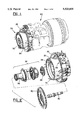
- FIG. 1 is a perspective view diagrammatically illustrating a gas turbine engine utilizing an inlet housing embodying the present invention
- FIG. 2 is a perspective exploded view of certain components illustrated in FIG. 1;
- FIG. 3 is an elevational cross section view illustrating fabrication of one component of the invention
- FIGS. 4A and 4B are detail cross section views illustrating parts of FIG. 3;
- FIGS. 5A, 5B, and 5C are detail perspective views diagrammatically illustrating steps used in the fabrication of another component of the invention.
- FIG. 5D is a detail cross section view of FIG. 5C
- FIG. 6 is a perspective exploded view illustrating a further step in the process of the invention.
- FIG. 7 is a perspective view illustrating yet another step in the process of the invention.
- FIG. 7A is a perspective view illustrating the completed fabrication of an inlet housing preform according to the invention.
- FIG. 8 is a cross section view, in elevation, illustrating yet a further step in the process of the invention.
- FIG. 9 is a perspective view of a completed inlet housing fabricated in accordance with the invention.
- FIG. 10 is a cross section view taken generally along line 10--10 in FIG. 9.
- FIG. 11 is a front elevation view of the inlet housing illustrated in FIG. 9.
- FIGS. 1 and 2 illustrate a typical gas turbine engine 20 incorporating an inlet housing 22 embodying the present invention.
- the inlet housing 22 was fabricated from magnesium.
- the metal including its flammability, its corrosiveness and other drawbacks, its use in new applications has been discontinued or restricted.
- the incorporation of toxic substances in magnesium alloys to enhance its strength and other properties has recently become prohibited.
- aluminum and titanium have become the materials of choice, but the added weight of aluminum and titanium as compared to magnesium has had a detrimental effect on the overall performance of the engine.
- the inlet housing 22 By reason of recent improvements in organic matrix composite technology and in braiding techniques, it has been found to be possible to produce the inlet housing 22 in a manner which eliminates problems of corrosion, can reduce weight by 10-20 percent relative to magnesium or up to 50 percent relative to the part fabricated from aluminum, and to carry loads in an engine which has an output approximately 40 percent greater than that of its predecessor.
- the inlet housing 22 of the invention includes inner and outer coaxial shells 24, 26 respectively, which are mutually supported so as to define an annular passageway 28 between them.
- the inner shell 24 is the hub member in the air inlet housing 22 of a gas turbine engine.
- an output group 32 is receivable within a generally cylindrical passage 34 extending through the inner shell 24, and is suitably attached to the inner shell.
- the output group 32 includes forward and aft bearings and bearing supports 36, 38 respectively, which, in turn, rotatably support a drive shaft 40 which is part of a power output train of the engine 20 connected with the power turbine (not shown) via appropriate mechanical means.
- a plurality of fibers 42 which may be, for example, glass, carbon, boron, or aramid, for example, KEVLAR brand, fibers, are braided in a known manner on a shaped mandrel 44.
- the braided fibers 42 may be laid down in a single course or in multiple courses, as desired.
- the mandrel 44 may be of any desired shape but, in FIG. 3, is illustrated as being generally cylindrical but smoothly tapering from a first end 46 to a second end 48. In any event, an outer surface 50 of the mandrel 44 is substantially a surface of revolution.
- a first course of fibers 52 is braided onto the outer surface 50 of the mandrel 44.
- a first annular metallic end plate 54 may be positioned on the first course of fibers 52 adjacent the first end 46 of the mandrel 44.
- a second annular metallic end plate 56 may be positioned on the first course of fibers 52 adjacent the second end 48 of the shaped mandrel 44.
- the braiding process then continues such that the braided fibers 42 intertwine and encircle the first and second end plates 54, 56 and thereby apply a second course of fibers 58 eventually overlying the first course of fibers 52.
- Suitable light weight filler material 60 which may be a polymer foam, for example, may be provided between the first and second courses 52, 58 and extending between the first and second end plates 54, 56, so as to avoid small radius curves in the first and second courses of fibers which would result in regions of high stress concentration. It will be understood that while, for the construction just described, there must be at least one course of fibers comprising the first course 52 and at least one course of fibers comprising the second course 58, there may, in actual fact, be many such courses should that be the desired construction. Additional filler material or a structural strengthening circumferential layer as indicated at 62 (FIG. 4A) and 64 (FIG. 4B) may also be provided for the structure of the inner shell 24 in order to avoid stress concentrations.
- Additional filler material or a structural strengthening circumferential layer as indicated at 62 (FIG. 4A) and 64 (FIG. 4B) may also be provided for the structure of the inner shell 24 in order to avoid stress concentrations.
- the filler material 62 and 64 would preferably be applied by means of braiding, it may be applied using other techniques such as by placement of a metallic ring or by use of a continuous fiber wind and it may be comprised of material other than glass, carbon, and boron fibers.
- the end plates 54, 56 are preferably provided with a plurality of circumferentially spaced tapped holes 66, 68, respectively, to receive studs 70 (FIG. 2) or other suitable fasteners for the purpose of attaching the mounting plate 30 or other components to the inner shell 24.
- the braided fibers 42 Upon the completion of the braiding operation as depicted in FIGS. 3, 4A, and 4b, the braided fibers 42 actually define an inner shell preform 71 (FIG.
- the first end ring or annulus plate 54 defines a leading end of the resulting inner shell preform 71 and the second end ring or annulus plate 56 defines a trailing end of the inner shell preform.
- FIGS. 5A, 5B, 5C, and 5D for a description of the fabrication of a plurality of duct preforms 72 (FIG. 5C and 6), a plurality of which will be integrated with the structure which results in the inlet housing 22.
- a plurality of fibers 74 are braided in the manner previously employed with respect to the inner shell preform 71 on a generally conical mandrel 76 to form an initial duct preform 78 (FIG. 5B) having a conical shape which is congruent with that of the mandrel 76.
- the initial duct preform 78 is removed from the conical mandrel 76 (see FIG. 5B).
- each modified duct preform 72 includes an inner duct surface 82 shaped to congruently mate with the outer surface 84 of the inner shell preform 71, an outer duct surface 86 spaced from the inner duct surface 82, and spaced apart lateral walls 88, 90 having opposed lateral surfaces 92, 94, respectively.
- the duct mold 80 may, for convenience and practicality, be actually comprised of three components for ease of removal of the duct preform 72.
- the duct mold 80 includes a central, substantially rigid member 96 and a pair of preferably resilient side members 98, 100 which actually contact the fibers of the duct preform 72.
- the side members 98, 100 can then be readily slipped out of the duct preform 72.
- the duct preforms 72 are administered onto the outer peripheral surface 84 of the inner shell preform 71 (see FIGS. 6 and 7).
- the modified duct preforms 72 are positioned in a side-by-side relationship at desired forward and aft locations on the inner shell preform and such that the lateral surfaces 92, 94 on adjacent modified duct preforms are coextensive and engaged.
- the plurality of the modified duct preforms completely circumscribe the inner shell preform.
- a plurality of fibers 102 are braided across the outer duct surfaces 86 (or onto a similarly shaped mandrel) and completely circumscribe the modified duct preforms 72 which, in turn, completely circumscribe the inner shell preform 71.
- an outer shell preform 104 is produced spaced from and coaxial with the inner shell preform. See FIG. 7A.
- an inlet housing preform 106 as illustrated in FIG. 8 is completed, being an integral structure comprised of the inner shell preform 71, the plurality of modified duct preforms 72, and the outer shell preform 104.
- the inlet housing preform 106 continues to envelop the shaped mandrel 44 and the duct molds 80.
- an outer mold 108 is administered to the outermost surface of the outer shell preform 104 so as to be in contiguous engagement therewith.
- Additional insert molds 110, 111 are positioned at a forward end of the inlet housing preform 106 to assure a void in that region following the next step of the process which is about to be described. It will be appreciated that the upper portions of FIG.
- a forward end cap 112 which is annularly shaped is placed in contiguous engagement with the outer mold 108, the insert molds 110, 111, and the shaped mandrel 44.
- a rear end cap 114 is placed in contiguous engagement with the trailing portions of the inlet housing preform 106 and, more specifically, with those associated regions of the outer mold 108, duct molds 80, and mandrel 44. The entire structure thus described is then supported between forward and rear press plates 116, 118, respectively, to maintain the entire structure in an integral relationship.
- suitable resin is applied, under suitable pressure, through aligned apertures 120, 122 in the press plate 118 and rear end cap 114, respectively and thereby into the interstices of the braided fibers in the entire inlet housing preform 106.
- the resin is applied until all voids within the inlet housing preform are filled.
- the entire structure illustrated in FIG. 8 is then placed in a suitable oven and the resin cured to thereby form an integral structure in the nature of the inlet housing 22 as illustrated in FIG. 9.
- the inlet housing 22 illustrated in FIG. 9 results upon removal of the pressplates 116, 118, the end caps 112, 114, the mandrel 44, the duct molds 80, the insert molds 110, 111, and the outer mold 108.
- the inlet housing 22 is comprised of the inner shell 24 and the outer shell 26.
- a plurality of circumferentially spaced strut members 124 result from the adjoining lateral walls 88, 90 of the juxtaposed modified duct preforms 72.
- the passageways 28 result from the spacing between the inner shell 24, the outer shell 26, and the strut members 124.
Abstract
An integral structure comprised of inner and outer coaxial shells mutually supported so as to define an annular passageway between the shells. The integral structure may be an air inlet housing for a gas turbine engine and the inner shell may be a hub member having a generally cylindrical passage extending therethrough for rotatably receiving a drive shaft. The inner shell has an outer surface of revolution. A plurality of duct preforms each include an inner duct surface shaped to congruently mate with said outer surface of said inner member, an outer duct surface spaced from said inner duct surface, and first and second lateral walls having opposed lateral surfaces. The duct member preforms are mounted onto the outer surface of the inner member in side-by-side relationship such that the first and second lateral walls on adjacent pairs of duct member preforms are coextensive and engaged. A coaxial outer shell preform is spaced from the inner member. Resin on the duct member preforms and the outer shell preform is cured to form an integral structure comprised of the inner member and outer shell member and a plurality of circumferentially spaced strut members defined by the first and second lateral walls.
Description
This is a divisional of application Ser. No. 08/012,581 filed on Feb. 3, 1993, now U.S. Pat. No. 5,362,344.
1. Field of the Invention
This invention relates generally to components fabricated from braided fiber composite materials and, in particular, to a method of making an integral structure so fabricated comprised of inner and outer coaxial shells mutually supported so as to define an annular passageway therebetween. Throughout the instant disclosure, the terms "braided fiber" or "braiding" are intended to include "woven or knitted fabric" or "weaving" or "knitting", although the specific construction of braided fiber and the specific method of braiding are considered to be preferable to the specific constructions of woven or knitted fabrics and the specific methods of weaving and knitting.
2. Description of the Prior Art
It is known to utilize elongate material, such as boron fibers, carbon fibers, and glass fibers for the reinforcement of gas turbine engine components such as compressor and turbine blades and vanes. In particular, the potential for usage of high modulus, high strength fibers, such as carbon, silicon carbide, boron, and glass in a resin or metal matrix is widely recognized. A typical application of such materials is disclosed in U.S. Pat. No. 5,018,271 to Bailey et al. In that particular instance, a composite gas turbine engine blade is disclosed as being made by braiding a plurality of fibers to form a preform. After braiding, the preform is placed in a mold provided with a blade shaped cavity and is subjected to matrix infiltration while the mold halves are pressed together by suitable pressing means such as a hydraulic cylinder. The goal of the present invention is to utilize a similar technique for the construction of a component which heretofore has only been constructed of metal, namely, magnesium, aluminum and, more recently, titanium and steel.
Accordingly, the present invention relates to a method is disclosed of making an integral structure comprised of inner and outer coaxial shells mutually supported so as to define an annular passageway between the shells. The integral structure may be an air inlet housing for a gas turbine engine and the inner shell may be a hub member having a generally cylindrical passage extending therethrough for rotatably receiving a drive shaft. The inner shell is formed by braiding on a shaped mandrel a plurality of fibers such as glass, boron, carbon, or the like, to form an inner shell preform having an outer surface of revolution.
A plurality of duct preforms are similarly formed on a desired shape of mandrel (conical, for example), then removed, and administered onto an outer peripheral surface of a duct mold so as to define a modified shape. As modified, each duct preform is comprised of an inner duct surface shaped to congruently mate with the outer surface of the inner shell preform, an outer duct surface spaced from the inner duct surface and first and second lateral walls having opposed lateral surfaces. The duct preforms are then positioned onto the outer surface of the inner shell preform in side-by-side relationship such that first and second lateral surfaces on adjacent duct preforms are coextensive and engaged, the plurality of duct preforms completely circumscribing the inner shell preform.
Then, a plurality of fibers are braided (or placed on a preform) across the plurality of the outer duct surfaces to form an outer shell preform spaced from and coaxial with the inner shell preform. Thereafter, resin is applied to the structure to encapsulate the braided inner shell preform, the braided duct preforms, and the braided outer shell preform and the resin is then cured to thereby form the integral structure.
A broad objective of the invention is to exploit the advantages offered by emerging organic matrix composites technology by tailoring resin systems to mold lightweight, low cost, engine components. A more specific objective is to achieve a structure which will exhibit the greatest possible strength between an inner shell and an outer shell with a plurality of circumferentially spaced integral strut members defining ducts while avoiding stress concentrations where the strut members join with the outer shell and with the inner shell. With this end in mind, an inlet housing for a gas turbine engine is sought which will outperform its magnesium or aluminum counterparts, specific objectives being to eliminate corrosion and reduce weight by at least 15% relative to an equivalent aluminum part.
A primary object of the invention, then, is to provide a ducted inlet housing assembly for a gas turbine engine which is an integral structure comprised of inner and outer coaxial shells mutually supported so as to define an annular passageway therebetween.
Another object of the invention is to provide such an integral structure which is not subject to corrosion, which is substantially lighter in weight, and which requires less maintenance than conventional constructions.
A further object of the invention is the provision of such an integral structure fabricated from braided fiber composition materials.
Still another object of the invention is the provision of such a structure which can be more economically manufactured operated, and maintained.
Yet a further object of the invention is to provide such a construction in which repeatability of manufacture can be assured and which assures uniform load transfer along the periphery of the structure. Still another object of the invention is to provide such a construction which can tolerate substantial damage, including ballistic damage, handling damage and the like without losing its effectiveness. Still another object of the invention is the provision, at leading and trailing ends of the inner and outer coaxial shells of metallic annular end plates which contain provision for fastening the structure to other components of the gas turbine engine.
Other and further features, advantages, and benefits of the invention will become apparent in the following description taken in conjunction with the following drawings. It is to be understood that the foregoing general description and the following detailed description are exemplary and explanatory but are not to be restrictive of the invention. The accompanying drawings which are incorporated in and constitute a part of this invention, illustrate one of the embodiments of the invention, and, together with the description, serve to explain the principles of the invention in general terms. Like numerals refer to like parts throughout the disclosure.
FIG. 1 is a perspective view diagrammatically illustrating a gas turbine engine utilizing an inlet housing embodying the present invention;
FIG. 2 is a perspective exploded view of certain components illustrated in FIG. 1;
FIG. 3 is an elevational cross section view illustrating fabrication of one component of the invention;
FIGS. 4A and 4B are detail cross section views illustrating parts of FIG. 3;
FIGS. 5A, 5B, and 5C are detail perspective views diagrammatically illustrating steps used in the fabrication of another component of the invention;
FIG. 5D is a detail cross section view of FIG. 5C;
FIG. 6 is a perspective exploded view illustrating a further step in the process of the invention;
FIG. 7 is a perspective view illustrating yet another step in the process of the invention;
FIG. 7A is a perspective view illustrating the completed fabrication of an inlet housing preform according to the invention;
FIG. 8 is a cross section view, in elevation, illustrating yet a further step in the process of the invention;
FIG. 9 is a perspective view of a completed inlet housing fabricated in accordance with the invention;
FIG. 10 is a cross section view taken generally along line 10--10 in FIG. 9; and
FIG. 11 is a front elevation view of the inlet housing illustrated in FIG. 9.
Turn now to the drawings, and, initially, to FIGS. 1 and 2 which illustrate a typical gas turbine engine 20 incorporating an inlet housing 22 embodying the present invention. Originally, the inlet housing 22 was fabricated from magnesium. However, because of difficulties experienced with that metal including its flammability, its corrosiveness and other drawbacks, its use in new applications has been discontinued or restricted. Specifically, the incorporation of toxic substances in magnesium alloys to enhance its strength and other properties has recently become prohibited. As a result, aluminum and titanium have become the materials of choice, but the added weight of aluminum and titanium as compared to magnesium has had a detrimental effect on the overall performance of the engine. By reason of recent improvements in organic matrix composite technology and in braiding techniques, it has been found to be possible to produce the inlet housing 22 in a manner which eliminates problems of corrosion, can reduce weight by 10-20 percent relative to magnesium or up to 50 percent relative to the part fabricated from aluminum, and to carry loads in an engine which has an output approximately 40 percent greater than that of its predecessor.
The inlet housing 22 of the invention includes inner and outer coaxial shells 24, 26 respectively, which are mutually supported so as to define an annular passageway 28 between them. As noted, the inner shell 24 is the hub member in the air inlet housing 22 of a gas turbine engine. With the aid of a mounting plate 30 which can be suitably attached to the inner shell 24, an output group 32 is receivable within a generally cylindrical passage 34 extending through the inner shell 24, and is suitably attached to the inner shell. The output group 32 includes forward and aft bearings and bearing supports 36, 38 respectively, which, in turn, rotatably support a drive shaft 40 which is part of a power output train of the engine 20 connected with the power turbine (not shown) via appropriate mechanical means.
Turn now to FIGS. 3, 4A and 4B for a description of the fabrication of the inner shell 24. A plurality of fibers 42 which may be, for example, glass, carbon, boron, or aramid, for example, KEVLAR brand, fibers, are braided in a known manner on a shaped mandrel 44. The braided fibers 42 may be laid down in a single course or in multiple courses, as desired. The mandrel 44 may be of any desired shape but, in FIG. 3, is illustrated as being generally cylindrical but smoothly tapering from a first end 46 to a second end 48. In any event, an outer surface 50 of the mandrel 44 is substantially a surface of revolution.
In a preferred construction, as illustrated more clearly in FIGS. 4A and 4B, a first course of fibers 52 is braided onto the outer surface 50 of the mandrel 44. In the course of the braiding process, a first annular metallic end plate 54 may be positioned on the first course of fibers 52 adjacent the first end 46 of the mandrel 44. At substantially the same time, a second annular metallic end plate 56 may be positioned on the first course of fibers 52 adjacent the second end 48 of the shaped mandrel 44. The braiding process then continues such that the braided fibers 42 intertwine and encircle the first and second end plates 54, 56 and thereby apply a second course of fibers 58 eventually overlying the first course of fibers 52. Suitable light weight filler material 60 which may be a polymer foam, for example, may be provided between the first and second courses 52, 58 and extending between the first and second end plates 54, 56, so as to avoid small radius curves in the first and second courses of fibers which would result in regions of high stress concentration. It will be understood that while, for the construction just described, there must be at least one course of fibers comprising the first course 52 and at least one course of fibers comprising the second course 58, there may, in actual fact, be many such courses should that be the desired construction. Additional filler material or a structural strengthening circumferential layer as indicated at 62 (FIG. 4A) and 64 (FIG. 4B) may also be provided for the structure of the inner shell 24 in order to avoid stress concentrations. Although the filler material 62 and 64 would preferably be applied by means of braiding, it may be applied using other techniques such as by placement of a metallic ring or by use of a continuous fiber wind and it may be comprised of material other than glass, carbon, and boron fibers. The end plates 54, 56 are preferably provided with a plurality of circumferentially spaced tapped holes 66, 68, respectively, to receive studs 70 (FIG. 2) or other suitable fasteners for the purpose of attaching the mounting plate 30 or other components to the inner shell 24. Upon the completion of the braiding operation as depicted in FIGS. 3, 4A, and 4b, the braided fibers 42 actually define an inner shell preform 71 (FIG. 6) which, like the mandrel 44, has an outer surface which is substantially a surface of revolution. The first end ring or annulus plate 54 defines a leading end of the resulting inner shell preform 71 and the second end ring or annulus plate 56 defines a trailing end of the inner shell preform.
Turn now to FIGS. 5A, 5B, 5C, and 5D for a description of the fabrication of a plurality of duct preforms 72 (FIG. 5C and 6), a plurality of which will be integrated with the structure which results in the inlet housing 22. To this end, a plurality of fibers 74 are braided in the manner previously employed with respect to the inner shell preform 71 on a generally conical mandrel 76 to form an initial duct preform 78 (FIG. 5B) having a conical shape which is congruent with that of the mandrel 76. Upon completion of the braiding operation, the initial duct preform 78 is removed from the conical mandrel 76 (see FIG. 5B). Then it is administered onto the outer peripheral surface of a duct mold 80 (FIG. 5C) so as to contiguously conform to the shape of the duct mold and thereby define a modified shape of the initial duct preform 78. As modified, viewing FIG. 6, each modified duct preform 72 includes an inner duct surface 82 shaped to congruently mate with the outer surface 84 of the inner shell preform 71, an outer duct surface 86 spaced from the inner duct surface 82, and spaced apart lateral walls 88, 90 having opposed lateral surfaces 92, 94, respectively.
Later in the process, but not at this time, after each modified duct preform 72 will have attained the shape of the duct mold 80, it is then removed. As seen in FIG. 5D, the duct mold 80 may, for convenience and practicality, be actually comprised of three components for ease of removal of the duct preform 72. As illustrated, the duct mold 80 includes a central, substantially rigid member 96 and a pair of preferably resilient side members 98, 100 which actually contact the fibers of the duct preform 72. As illustrated, upon removal of the wedge-shaped central member 96, the side members 98, 100 can then be readily slipped out of the duct preform 72. Of course, it will be appreciated that numerous other constructions of the duct mold 80 can be utilized and that the construction described is only for purposes of explanation. After formation of a plurality of duct preforms 72 on their associated duct molds 80, the duct preforms, together with their associated duct molds, are administered onto the outer peripheral surface 84 of the inner shell preform 71 (see FIGS. 6 and 7). With their inner duct surfaces 82 in mating engagement with the outer peripheral surface 84 of the inner shell preform, the modified duct preforms 72 are positioned in a side-by-side relationship at desired forward and aft locations on the inner shell preform and such that the lateral surfaces 92, 94 on adjacent modified duct preforms are coextensive and engaged. As seen in FIG. 7, the plurality of the modified duct preforms completely circumscribe the inner shell preform.
Thereupon, as indicated in FIG. 7, a plurality of fibers 102 are braided across the outer duct surfaces 86 (or onto a similarly shaped mandrel) and completely circumscribe the modified duct preforms 72 which, in turn, completely circumscribe the inner shell preform 71. By so doing, an outer shell preform 104 is produced spaced from and coaxial with the inner shell preform. See FIG. 7A.
In this manner, fabrication of an inlet housing preform 106 as illustrated in FIG. 8 is completed, being an integral structure comprised of the inner shell preform 71, the plurality of modified duct preforms 72, and the outer shell preform 104. At this stage, however, the inlet housing preform 106 continues to envelop the shaped mandrel 44 and the duct molds 80. Thereupon, an outer mold 108 is administered to the outermost surface of the outer shell preform 104 so as to be in contiguous engagement therewith. Additional insert molds 110, 111 are positioned at a forward end of the inlet housing preform 106 to assure a void in that region following the next step of the process which is about to be described. It will be appreciated that the upper portions of FIG. 8 correspond to the forward portions of the inlet housing preform 106. Thereupon, a forward end cap 112 which is annularly shaped is placed in contiguous engagement with the outer mold 108, the insert molds 110, 111, and the shaped mandrel 44. In similar fashion, a rear end cap 114 is placed in contiguous engagement with the trailing portions of the inlet housing preform 106 and, more specifically, with those associated regions of the outer mold 108, duct molds 80, and mandrel 44. The entire structure thus described is then supported between forward and rear press plates 116, 118, respectively, to maintain the entire structure in an integral relationship.
Thereafter, suitable resin is applied, under suitable pressure, through aligned apertures 120, 122 in the press plate 118 and rear end cap 114, respectively and thereby into the interstices of the braided fibers in the entire inlet housing preform 106. The resin is applied until all voids within the inlet housing preform are filled. The entire structure illustrated in FIG. 8 is then placed in a suitable oven and the resin cured to thereby form an integral structure in the nature of the inlet housing 22 as illustrated in FIG. 9. The inlet housing 22 illustrated in FIG. 9 results upon removal of the pressplates 116, 118, the end caps 112, 114, the mandrel 44, the duct molds 80, the insert molds 110, 111, and the outer mold 108. As previously described, the inlet housing 22 is comprised of the inner shell 24 and the outer shell 26. A plurality of circumferentially spaced strut members 124 result from the adjoining lateral walls 88, 90 of the juxtaposed modified duct preforms 72. The passageways 28 result from the spacing between the inner shell 24, the outer shell 26, and the strut members 124.
While preferred embodiments of the invention have been disclosed in detail, it should be understood by those skilled in the art that various other modifications may be made to the illustrated embodiments without departing from the scope of the invention as described in the specification and defined in the appended claims.
Claims (4)
1. An integral structure comprising: an inner member having an outer surface which is substantially a surface of revolution; an outer shell member spaced from and coaxial with said inner member; and a plurality of circumferentially spaced strut members spanning the space between the inner member and outer shell member, said strut members and outer shell member made by:
providing a plurality of duct member preforms comprised of a plurality of braided fibers, each of said duct member preforms including an inner duct surface shaped to congruently mate with said outer surface of said inner member, an outer duct surface spaced from said inner duct surface, and first and second lateral walls having opposed lateral surfaces, said duct member preforms being mounted onto said outer surface of said inner member in side-by-side relationship such that said first and second lateral walls on adjacent pairs of said duct member preforms are coextensive and engaged, the plurality of said duct member preforms completely circumscribing said inner member;
forming an outer shell preform by braiding a plurality of fibers across the plurality of said outer duct surfaces;
applying resin at least to said duct member preforms and to said outer shell preform to encapsulate said duct member preforms and said outer shell preform; and
then curing the resin to thereby form said integral structure, said spaced strut members defined by said engaged first and second lateral walls.
2. An integral structure as set forth in claim 1 wherein said inner member includes:
an elongated inner shell member having a generally cylindrical passage extending therethrough, said shell member extending between an annular leading end and an annular trailing end;
a first metallic annular end plate including fastening means fixed to said leading end of said inner shell member; and
a second metallic annular end plate including fastening means fixed to said leading end of said inner shell member; and
a second metallic annular end plate including fastening means fixed to said trailing end of said inner shell member;
said inner shell member including a preform comprised of a plurality of braided fibers, said first and second annular end plates being intertwined by said fibers for fixation thereof to said inner shell member, resin being applied to said preform, then cured to thereby form said integral structure.
3. An air inlet housing for a gas turbine engine comprising:
a hub member having a generally cylindrical passage extending therethrough, said hub member extending between an annular leading end and an annular trailing end and having an outer surface which is substantially a surface of revolution;
a drive shaft extending through said cylindrical passage of said hub member;
bearing means rotatably mounting said drive shaft on said hub member for rotation of the drive shaft about its longitudinal axis;
an outer shell member spaced from and coaxial with said hub member; and
a plurality of circumferentially spaced strut members integral with said outer shell member and extending across the space between said outer shell member and said hub member, said strut members and said outer shell member made by:
providing a plurality of duct member preforms comprised of a plurality of braided fibers, each of said duct member preforms including an inner duct surface shaped to congruently mate with said outer surface of said hub member, an outer duct surface spaced from said inner duct surface, and first and second lateral walls having opposed lateral surfaces, said duct member preforms being mounted onto said outer surface of said hub member in side-by-side relationship such that said first and second lateral walls on adjacent pairs of said duct member preforms are coextensive and engaged, the plurality of said duct member preforms completely circumscribing said hub member;
forming an outer shell preform by braiding a plurality of fibers across the plurality of said outer duct surfaces;
applying resin at least to said duct member preforms and to said outer shell preform to encapsulate said duct member preforms and said outer shell preform; and
then curing the resin to thereby form said outer shell member with said plurality of circumferentially spaced strut members being defined by said engaged first and second lateral walls.
4. An air inlet housing as set forth in claim 3 wherein said hub member includes:
a first metallic annular end plate including fastening means fixed to said leading end of said hub member; and
a second metallic annular end plate including fastening means fixed to said trailing end of said hub member;
said hub member including a preform comprised of a plurality of braided fibers, said first and second annular end plates being intertwined by said fibers for fixation thereof to said hub member, resin being applied to said preform, then cured to thereby integrally form said hub member, said outer shell member and said plurality of said circumferentially spaced strut members.
Priority Applications (1)
| Application Number | Priority Date | Filing Date | Title |
|---|---|---|---|
| US08/326,092 US5525035A (en) | 1993-02-03 | 1994-10-19 | Ducted support housing assembly |
Applications Claiming Priority (2)
| Application Number | Priority Date | Filing Date | Title |
|---|---|---|---|
| US08/012,581 US5362344A (en) | 1993-02-03 | 1993-02-03 | Ducted support housing assembly |
| US08/326,092 US5525035A (en) | 1993-02-03 | 1994-10-19 | Ducted support housing assembly |
Related Parent Applications (1)
| Application Number | Title | Priority Date | Filing Date |
|---|---|---|---|
| US08/012,581 Division US5362344A (en) | 1993-02-03 | 1993-02-03 | Ducted support housing assembly |
Publications (1)
| Publication Number | Publication Date |
|---|---|
| US5525035A true US5525035A (en) | 1996-06-11 |
Family
ID=21755640
Family Applications (2)
| Application Number | Title | Priority Date | Filing Date |
|---|---|---|---|
| US08/012,581 Expired - Lifetime US5362344A (en) | 1993-02-03 | 1993-02-03 | Ducted support housing assembly |
| US08/326,092 Expired - Lifetime US5525035A (en) | 1993-02-03 | 1994-10-19 | Ducted support housing assembly |
Family Applications Before (1)
| Application Number | Title | Priority Date | Filing Date |
|---|---|---|---|
| US08/012,581 Expired - Lifetime US5362344A (en) | 1993-02-03 | 1993-02-03 | Ducted support housing assembly |
Country Status (1)
| Country | Link |
|---|---|
| US (2) | US5362344A (en) |
Cited By (10)
| Publication number | Priority date | Publication date | Assignee | Title |
|---|---|---|---|---|
| US6854960B2 (en) | 2002-06-24 | 2005-02-15 | Electric Boat Corporation | Segmented composite impeller/propeller arrangement and manufacturing method |
| US20060134396A1 (en) * | 2004-12-22 | 2006-06-22 | General Electric Company | Reinforced matrix composite containment duct |
| US20060130993A1 (en) * | 2004-12-22 | 2006-06-22 | General Electric Company | Method for fabricating reinforced composite materials |
| US20060269405A1 (en) * | 2005-05-31 | 2006-11-30 | United Technologies Corporation | Modular fan inlet case |
| EP1728991A2 (en) | 2005-05-31 | 2006-12-06 | United Technologies Corporation | Electrothermal inlet ice protection system |
| US20070018048A1 (en) * | 2005-07-20 | 2007-01-25 | Lyders David R | Winged structural joint and articles employing the joint |
| US20070248454A1 (en) * | 2006-04-19 | 2007-10-25 | Davis Walter D | Device for changing the pressure of a fluid |
| US20080022524A1 (en) * | 2006-03-10 | 2008-01-31 | Karl Schreiber | Intake cone in a fiber compound material for a gas turbine engine and method for its manufacture |
| EP3165448A1 (en) * | 2015-11-05 | 2017-05-10 | Airbus Operations, S.L. | Method, forming and injection tool for manufacturing an aperture surrounding frame for an aircraft fuselage, and frame obtained thereof |
| EP3225784A1 (en) * | 2016-03-30 | 2017-10-04 | General Electric Company | Flowpath assembly for a gas turbine engine |
Families Citing this family (8)
| Publication number | Priority date | Publication date | Assignee | Title |
|---|---|---|---|---|
| US5362344A (en) * | 1993-02-03 | 1994-11-08 | Avco Corporation | Ducted support housing assembly |
| FR2707552B1 (en) * | 1993-06-30 | 1995-10-13 | Aerospatiale | Method of manufacturing a part made of composite material, a central body and fins and missile body thus obtained. |
| US5724715A (en) * | 1996-07-02 | 1998-03-10 | Addax, Inc. | Composite flange for drive shafts |
| USH1872H (en) * | 1997-03-03 | 2000-10-03 | The United States Of America As Represented By The Secretary Of The Air Force | Modular fiber reinforced plastic enclosed bridge |
| US20090120101A1 (en) * | 2007-10-31 | 2009-05-14 | United Technologies Corp. | Organic Matrix Composite Components, Systems Using Such Components, and Methods for Manufacturing Such Components |
| US20150266572A1 (en) * | 2014-03-21 | 2015-09-24 | Hamilton Sundstrand Corporation | Propeller blade having compliant spar core |
| CN109747181A (en) * | 2019-03-04 | 2019-05-14 | 保定国奥新能源工程材料科技有限责任公司 | The manufacturing method of duct |
| CN113550065B (en) * | 2021-07-09 | 2023-03-21 | 艾柯医疗器械(北京)股份有限公司 | Braided tube manufacturing method and tool |
Citations (5)
| Publication number | Priority date | Publication date | Assignee | Title |
|---|---|---|---|---|
| US4452565A (en) * | 1981-12-21 | 1984-06-05 | United Technologies Corporation | Containment structure |
| US4452563A (en) * | 1981-12-21 | 1984-06-05 | United Technologies Corporation | Containment structure |
| US4699567A (en) * | 1984-06-07 | 1987-10-13 | Rolls-Royce Plc | Fan duct casing |
| US5362344A (en) * | 1993-02-03 | 1994-11-08 | Avco Corporation | Ducted support housing assembly |
| GB2279413A (en) * | 1993-06-10 | 1995-01-04 | Snecma | Inter-blade platform for a bladed disc of a turbomachine rotor |
Family Cites Families (16)
| Publication number | Priority date | Publication date | Assignee | Title |
|---|---|---|---|---|
| US3221398A (en) * | 1961-01-25 | 1965-12-07 | Ruth D Mayne | Method of manufacturing a turbine type blower wheel |
| GB1054608A (en) * | 1965-09-16 | |||
| US3549444A (en) * | 1967-12-28 | 1970-12-22 | Harry S Katz | Filament wound blade and compressor |
| GB1197647A (en) * | 1968-02-08 | 1970-07-08 | Rolls Royce | Improvements in or relating to Blades for a Gas Turbine Engine. |
| US3511578A (en) * | 1968-07-22 | 1970-05-12 | American Air Filter Co | Blower wheel |
| US4238540A (en) * | 1979-05-29 | 1980-12-09 | Celanese Corporation | Fiber reinforced composite shaft with metallic connector sleeves mounted by connector ring interlock |
| US4494436A (en) * | 1983-09-02 | 1985-01-22 | Elfin Corporation | Apparatus for manufacturing resin impregnated fiber braided products |
| US4519290A (en) * | 1983-11-16 | 1985-05-28 | Thiokol Corporation | Braided preform for refractory articles and method of making |
| FR2565159B1 (en) * | 1984-05-30 | 1986-10-17 | Aerospatiale | METHOD FOR MANUFACTURING A PART OF A COMPLEX STRUCTURE BY FILAMENTARY WINDING AND A PART ARISING FROM THE PROCESS |
| GB2161110B (en) * | 1984-07-07 | 1988-03-23 | Rolls Royce | An annular bladed member having an integral shroud and a method of manufacture thereof |
| US4734146A (en) * | 1986-03-31 | 1988-03-29 | Rockwell International Corporation | Method of producing a composite sine wave beam |
| US4846908A (en) * | 1987-04-03 | 1989-07-11 | E. I. Du Pont De Nemours And Company | Process for preparing a fiber reinforced resin matrix preform |
| US5018271A (en) * | 1988-09-09 | 1991-05-28 | Airfoil Textron Inc. | Method of making a composite blade with divergent root |
| US4930987A (en) * | 1989-05-24 | 1990-06-05 | Brad Stahl | Marine propeller and hub assembly of plastic |
| US4991766A (en) * | 1989-10-05 | 1991-02-12 | Hunnicutt Iii Joseph W | Process of manufacturing a conical flight assembly |
| FR2655906B1 (en) * | 1989-12-19 | 1992-04-03 | Aerospatiale | PROCESS FOR THE PRODUCTION BY A FILAMENTARY WINDING OF AN ANNULAR BOX WITH INTERNAL STIFFENERS. |
-
1993
- 1993-02-03 US US08/012,581 patent/US5362344A/en not_active Expired - Lifetime
-
1994
- 1994-10-19 US US08/326,092 patent/US5525035A/en not_active Expired - Lifetime
Patent Citations (5)
| Publication number | Priority date | Publication date | Assignee | Title |
|---|---|---|---|---|
| US4452565A (en) * | 1981-12-21 | 1984-06-05 | United Technologies Corporation | Containment structure |
| US4452563A (en) * | 1981-12-21 | 1984-06-05 | United Technologies Corporation | Containment structure |
| US4699567A (en) * | 1984-06-07 | 1987-10-13 | Rolls-Royce Plc | Fan duct casing |
| US5362344A (en) * | 1993-02-03 | 1994-11-08 | Avco Corporation | Ducted support housing assembly |
| GB2279413A (en) * | 1993-06-10 | 1995-01-04 | Snecma | Inter-blade platform for a bladed disc of a turbomachine rotor |
Cited By (25)
| Publication number | Priority date | Publication date | Assignee | Title |
|---|---|---|---|---|
| US6854960B2 (en) | 2002-06-24 | 2005-02-15 | Electric Boat Corporation | Segmented composite impeller/propeller arrangement and manufacturing method |
| US7332049B2 (en) | 2004-12-22 | 2008-02-19 | General Electric Company | Method for fabricating reinforced composite materials |
| US20060134396A1 (en) * | 2004-12-22 | 2006-06-22 | General Electric Company | Reinforced matrix composite containment duct |
| US20060130993A1 (en) * | 2004-12-22 | 2006-06-22 | General Electric Company | Method for fabricating reinforced composite materials |
| EP1674245A1 (en) * | 2004-12-22 | 2006-06-28 | The General Electric Company | Method for fabricating reinforced composite materials with low porosity |
| EP1674244A1 (en) * | 2004-12-22 | 2006-06-28 | The General Electric Company | A fibre reinforced composite containment duct for gas turbine engines |
| US7867566B2 (en) | 2004-12-22 | 2011-01-11 | General Electric Company | Method for fabricating reinforced composite materials |
| US20090142496A1 (en) * | 2004-12-22 | 2009-06-04 | General Electric Company | Method for fabricating reinforced composite materials |
| US7431978B2 (en) | 2004-12-22 | 2008-10-07 | General Electric Company | Reinforced matrix composite containment duct |
| EP1728991A2 (en) | 2005-05-31 | 2006-12-06 | United Technologies Corporation | Electrothermal inlet ice protection system |
| US8366047B2 (en) | 2005-05-31 | 2013-02-05 | United Technologies Corporation | Electrothermal inlet ice protection system |
| US7950899B2 (en) | 2005-05-31 | 2011-05-31 | United Technologies Corporation | Modular fan inlet case |
| US20060269405A1 (en) * | 2005-05-31 | 2006-11-30 | United Technologies Corporation | Modular fan inlet case |
| EP1728974A3 (en) * | 2005-05-31 | 2009-09-30 | United Technologies Corporation | Modular fan inlet case |
| US20060280600A1 (en) * | 2005-05-31 | 2006-12-14 | United Technologies Corporation | Electrothermal inlet ice protection system |
| EP1728991A3 (en) * | 2005-05-31 | 2009-09-30 | United Technologies Corporation | Electrothermal inlet ice protection system |
| US7438524B2 (en) * | 2005-07-20 | 2008-10-21 | United Technologies Corporation | Winged structural joint and articles employing the joint |
| US20070018048A1 (en) * | 2005-07-20 | 2007-01-25 | Lyders David R | Winged structural joint and articles employing the joint |
| US20080022524A1 (en) * | 2006-03-10 | 2008-01-31 | Karl Schreiber | Intake cone in a fiber compound material for a gas turbine engine and method for its manufacture |
| US8677622B2 (en) * | 2006-03-10 | 2014-03-25 | Rolls-Royce Deutschland Ltd & Co Kg | Intake cone in a fiber compound material for a gas turbine engine and method for its manufacture |
| US20070248454A1 (en) * | 2006-04-19 | 2007-10-25 | Davis Walter D | Device for changing the pressure of a fluid |
| EP3165448A1 (en) * | 2015-11-05 | 2017-05-10 | Airbus Operations, S.L. | Method, forming and injection tool for manufacturing an aperture surrounding frame for an aircraft fuselage, and frame obtained thereof |
| US10293557B2 (en) | 2015-11-05 | 2019-05-21 | Airbus Operations, S.L. | Method, forming and injection tool for manufacturing an aperture surrounding frame for an aircraft fuselage, and frame obtained thereof |
| EP3225784A1 (en) * | 2016-03-30 | 2017-10-04 | General Electric Company | Flowpath assembly for a gas turbine engine |
| US10443415B2 (en) | 2016-03-30 | 2019-10-15 | General Electric Company | Flowpath assembly for a gas turbine engine |
Also Published As
| Publication number | Publication date |
|---|---|
| US5362344A (en) | 1994-11-08 |
Similar Documents
| Publication | Publication Date | Title |
|---|---|---|
| US5525035A (en) | Ducted support housing assembly | |
| US3554668A (en) | Turbomachine rotor | |
| US5921754A (en) | Composite turbine rotor | |
| US5222297A (en) | Composite blade manufacture | |
| KR101488014B1 (en) | Methods for reducing stress on composite structures | |
| KR101401214B1 (en) | Methods for making structures having mounting flanges | |
| US4063847A (en) | Gas turbine engine casing | |
| KR101488013B1 (en) | Articles comprising composite structures having mounting flanges | |
| US4354804A (en) | Composite turbine wheel, method of manufacture and fixture therefor | |
| EP1900502A1 (en) | Method for making composite corner | |
| AU2004247325A1 (en) | Wind turbine blade and method of manufacturing thereof | |
| US4191510A (en) | Axial flow compressor rotor drum | |
| EP3093450B1 (en) | Steel soft wall fan case | |
| CA2718270A1 (en) | Composite load-bearing rotating ring and process therefor | |
| US4878821A (en) | Detachable anti-rupture ring for the housing of a turbo power plant | |
| CN108453969B (en) | Method for manufacturing a wind turbine rotor blade root section and related wind turbine blade | |
| KR950013725B1 (en) | Composite helicopter swashplate | |
| US5091029A (en) | Method of manufacturing a unitary, multi-legged helicopter rotor flexbeam made solely of composite materials | |
| US20080116334A1 (en) | Methods for fabricating composite structures having mounting flanges | |
| US3616508A (en) | Method of making compressor or turbine rotor or stator blades | |
| GB2175273A (en) | A filament-wound, torque-transmitting, drive structure | |
| JP5009757B2 (en) | Device for use with a structure having a mounting flange | |
| US7195417B2 (en) | Composite tie rod | |
| DE102018200309A1 (en) | Rolling bearing assembly and method | |
| US4862763A (en) | Method and apparatus for manufacturing high speed rotors |
Legal Events
| Date | Code | Title | Description |
|---|---|---|---|
| STCF | Information on status: patent grant |
Free format text: PATENTED CASE |
|
| FEPP | Fee payment procedure |
Free format text: PAYOR NUMBER ASSIGNED (ORIGINAL EVENT CODE: ASPN); ENTITY STATUS OF PATENT OWNER: LARGE ENTITY |
|
| FPAY | Fee payment |
Year of fee payment: 4 |
|
| FPAY | Fee payment |
Year of fee payment: 8 |
|
| FPAY | Fee payment |
Year of fee payment: 12 |