US5518808A - Luminescent materials prepared by coating luminescent compositions onto substrate particles - Google Patents
Luminescent materials prepared by coating luminescent compositions onto substrate particles Download PDFInfo
- Publication number
- US5518808A US5518808A US08/148,734 US14873493A US5518808A US 5518808 A US5518808 A US 5518808A US 14873493 A US14873493 A US 14873493A US 5518808 A US5518808 A US 5518808A
- Authority
- US
- United States
- Prior art keywords
- luminescent
- composition
- coating
- inert core
- core
- Prior art date
- Legal status (The legal status is an assumption and is not a legal conclusion. Google has not performed a legal analysis and makes no representation as to the accuracy of the status listed.)
- Expired - Lifetime
Links
Images


Classifications
-
- C—CHEMISTRY; METALLURGY
- C09—DYES; PAINTS; POLISHES; NATURAL RESINS; ADHESIVES; COMPOSITIONS NOT OTHERWISE PROVIDED FOR; APPLICATIONS OF MATERIALS NOT OTHERWISE PROVIDED FOR
- C09K—MATERIALS FOR MISCELLANEOUS APPLICATIONS, NOT PROVIDED FOR ELSEWHERE
- C09K11/00—Luminescent, e.g. electroluminescent, chemiluminescent materials
- C09K11/02—Use of particular materials as binders, particle coatings or suspension media therefor
- C09K11/025—Use of particular materials as binders, particle coatings or suspension media therefor non-luminescent particle coatings or suspension media
-
- C—CHEMISTRY; METALLURGY
- C09—DYES; PAINTS; POLISHES; NATURAL RESINS; ADHESIVES; COMPOSITIONS NOT OTHERWISE PROVIDED FOR; APPLICATIONS OF MATERIALS NOT OTHERWISE PROVIDED FOR
- C09K—MATERIALS FOR MISCELLANEOUS APPLICATIONS, NOT PROVIDED FOR ELSEWHERE
- C09K11/00—Luminescent, e.g. electroluminescent, chemiluminescent materials
- C09K11/08—Luminescent, e.g. electroluminescent, chemiluminescent materials containing inorganic luminescent materials
- C09K11/77—Luminescent, e.g. electroluminescent, chemiluminescent materials containing inorganic luminescent materials containing rare earth metals
- C09K11/7766—Luminescent, e.g. electroluminescent, chemiluminescent materials containing inorganic luminescent materials containing rare earth metals containing two or more rare earth metals
- C09K11/7774—Aluminates
-
- C—CHEMISTRY; METALLURGY
- C09—DYES; PAINTS; POLISHES; NATURAL RESINS; ADHESIVES; COMPOSITIONS NOT OTHERWISE PROVIDED FOR; APPLICATIONS OF MATERIALS NOT OTHERWISE PROVIDED FOR
- C09K—MATERIALS FOR MISCELLANEOUS APPLICATIONS, NOT PROVIDED FOR ELSEWHERE
- C09K11/00—Luminescent, e.g. electroluminescent, chemiluminescent materials
- C09K11/08—Luminescent, e.g. electroluminescent, chemiluminescent materials containing inorganic luminescent materials
- C09K11/77—Luminescent, e.g. electroluminescent, chemiluminescent materials containing inorganic luminescent materials containing rare earth metals
- C09K11/7783—Luminescent, e.g. electroluminescent, chemiluminescent materials containing inorganic luminescent materials containing rare earth metals containing two or more rare earth metals one of which being europium
- C09K11/7784—Chalcogenides
- C09K11/7787—Oxides
-
- C—CHEMISTRY; METALLURGY
- C09—DYES; PAINTS; POLISHES; NATURAL RESINS; ADHESIVES; COMPOSITIONS NOT OTHERWISE PROVIDED FOR; APPLICATIONS OF MATERIALS NOT OTHERWISE PROVIDED FOR
- C09K—MATERIALS FOR MISCELLANEOUS APPLICATIONS, NOT PROVIDED FOR ELSEWHERE
- C09K11/00—Luminescent, e.g. electroluminescent, chemiluminescent materials
- C09K11/08—Luminescent, e.g. electroluminescent, chemiluminescent materials containing inorganic luminescent materials
- C09K11/77—Luminescent, e.g. electroluminescent, chemiluminescent materials containing inorganic luminescent materials containing rare earth metals
- C09K11/7783—Luminescent, e.g. electroluminescent, chemiluminescent materials containing inorganic luminescent materials containing rare earth metals containing two or more rare earth metals one of which being europium
- C09K11/7794—Vanadates; Chromates; Molybdates; Tungstates
-
- H—ELECTRICITY
- H01—ELECTRIC ELEMENTS
- H01J—ELECTRIC DISCHARGE TUBES OR DISCHARGE LAMPS
- H01J11/00—Gas-filled discharge tubes with alternating current induction of the discharge, e.g. alternating current plasma display panels [AC-PDP]; Gas-filled discharge tubes without any main electrode inside the vessel; Gas-filled discharge tubes with at least one main electrode outside the vessel
- H01J11/10—AC-PDPs with at least one main electrode being out of contact with the plasma
- H01J11/14—AC-PDPs with at least one main electrode being out of contact with the plasma with main electrodes provided only on one side of the discharge space
-
- H—ELECTRICITY
- H01—ELECTRIC ELEMENTS
- H01J—ELECTRIC DISCHARGE TUBES OR DISCHARGE LAMPS
- H01J11/00—Gas-filled discharge tubes with alternating current induction of the discharge, e.g. alternating current plasma display panels [AC-PDP]; Gas-filled discharge tubes without any main electrode inside the vessel; Gas-filled discharge tubes with at least one main electrode outside the vessel
- H01J11/20—Constructional details
- H01J11/34—Vessels, containers or parts thereof, e.g. substrates
- H01J11/42—Fluorescent layers
-
- Y—GENERAL TAGGING OF NEW TECHNOLOGICAL DEVELOPMENTS; GENERAL TAGGING OF CROSS-SECTIONAL TECHNOLOGIES SPANNING OVER SEVERAL SECTIONS OF THE IPC; TECHNICAL SUBJECTS COVERED BY FORMER USPC CROSS-REFERENCE ART COLLECTIONS [XRACs] AND DIGESTS
- Y10—TECHNICAL SUBJECTS COVERED BY FORMER USPC
- Y10S—TECHNICAL SUBJECTS COVERED BY FORMER USPC CROSS-REFERENCE ART COLLECTIONS [XRACs] AND DIGESTS
- Y10S428/00—Stock material or miscellaneous articles
- Y10S428/917—Electroluminescent
-
- Y—GENERAL TAGGING OF NEW TECHNOLOGICAL DEVELOPMENTS; GENERAL TAGGING OF CROSS-SECTIONAL TECHNOLOGIES SPANNING OVER SEVERAL SECTIONS OF THE IPC; TECHNICAL SUBJECTS COVERED BY FORMER USPC CROSS-REFERENCE ART COLLECTIONS [XRACs] AND DIGESTS
- Y10—TECHNICAL SUBJECTS COVERED BY FORMER USPC
- Y10T—TECHNICAL SUBJECTS COVERED BY FORMER US CLASSIFICATION
- Y10T428/00—Stock material or miscellaneous articles
- Y10T428/25—Web or sheet containing structurally defined element or component and including a second component containing structurally defined particles
- Y10T428/258—Alkali metal or alkaline earth metal or compound thereof
-
- Y—GENERAL TAGGING OF NEW TECHNOLOGICAL DEVELOPMENTS; GENERAL TAGGING OF CROSS-SECTIONAL TECHNOLOGIES SPANNING OVER SEVERAL SECTIONS OF THE IPC; TECHNICAL SUBJECTS COVERED BY FORMER USPC CROSS-REFERENCE ART COLLECTIONS [XRACs] AND DIGESTS
- Y10—TECHNICAL SUBJECTS COVERED BY FORMER USPC
- Y10T—TECHNICAL SUBJECTS COVERED BY FORMER US CLASSIFICATION
- Y10T428/00—Stock material or miscellaneous articles
- Y10T428/25—Web or sheet containing structurally defined element or component and including a second component containing structurally defined particles
- Y10T428/259—Silicic material
-
- Y—GENERAL TAGGING OF NEW TECHNOLOGICAL DEVELOPMENTS; GENERAL TAGGING OF CROSS-SECTIONAL TECHNOLOGIES SPANNING OVER SEVERAL SECTIONS OF THE IPC; TECHNICAL SUBJECTS COVERED BY FORMER USPC CROSS-REFERENCE ART COLLECTIONS [XRACs] AND DIGESTS
- Y10—TECHNICAL SUBJECTS COVERED BY FORMER USPC
- Y10T—TECHNICAL SUBJECTS COVERED BY FORMER US CLASSIFICATION
- Y10T428/00—Stock material or miscellaneous articles
- Y10T428/26—Web or sheet containing structurally defined element or component, the element or component having a specified physical dimension
- Y10T428/266—Web or sheet containing structurally defined element or component, the element or component having a specified physical dimension of base or substrate
-
- Y—GENERAL TAGGING OF NEW TECHNOLOGICAL DEVELOPMENTS; GENERAL TAGGING OF CROSS-SECTIONAL TECHNOLOGIES SPANNING OVER SEVERAL SECTIONS OF THE IPC; TECHNICAL SUBJECTS COVERED BY FORMER USPC CROSS-REFERENCE ART COLLECTIONS [XRACs] AND DIGESTS
- Y10—TECHNICAL SUBJECTS COVERED BY FORMER USPC
- Y10T—TECHNICAL SUBJECTS COVERED BY FORMER US CLASSIFICATION
- Y10T428/00—Stock material or miscellaneous articles
- Y10T428/29—Coated or structually defined flake, particle, cell, strand, strand portion, rod, filament, macroscopic fiber or mass thereof
- Y10T428/2982—Particulate matter [e.g., sphere, flake, etc.]
- Y10T428/2991—Coated
- Y10T428/2993—Silicic or refractory material containing [e.g., tungsten oxide, glass, cement, etc.]
- Y10T428/2996—Glass particles or spheres
-
- Y—GENERAL TAGGING OF NEW TECHNOLOGICAL DEVELOPMENTS; GENERAL TAGGING OF CROSS-SECTIONAL TECHNOLOGIES SPANNING OVER SEVERAL SECTIONS OF THE IPC; TECHNICAL SUBJECTS COVERED BY FORMER USPC CROSS-REFERENCE ART COLLECTIONS [XRACs] AND DIGESTS
- Y10—TECHNICAL SUBJECTS COVERED BY FORMER USPC
- Y10T—TECHNICAL SUBJECTS COVERED BY FORMER US CLASSIFICATION
- Y10T428/00—Stock material or miscellaneous articles
- Y10T428/29—Coated or structually defined flake, particle, cell, strand, strand portion, rod, filament, macroscopic fiber or mass thereof
- Y10T428/2982—Particulate matter [e.g., sphere, flake, etc.]
- Y10T428/2991—Coated
- Y10T428/2998—Coated including synthetic resin or polymer
Definitions
- the present invention relates to a novel, cost efficient, luminescent composition, and processes for making the composition.
- Luminescent materials or phosphors comprise a host material which together with one or more activators converts absorbed energy into radiant energy.
- Some of the most widely used host materials are calcium halophosphate, barium magnesium aluminate, magnesium aluminate, strontium chloroapatite, zinc silicate and the oxides, oxysulfides, phosphates, vanadates and silicates of yttrium, gadolinium or lanthanum.
- Commonly used activators are rare-earth ions such as europium II and III, terbium III, cerium III, and tin II.
- compounds containing the host and activator materials are mixed together by a mechanical procedure, such as milling or micronizing, and then calcined to produce fine powder phosphors of relatively uniform composition. These powders may be bonded as coatings to the surface of a substrate, typically glass, for use in a variety of applications.
- Rare-earth oxide (REO) activated phosphors are used in trichromatic lamps, cathode ray tubes (CRT), color television (CTV), high definition television (HDTV) screens, among others. Many of the rare-earth oxides are very expensive and this has limited their use in a number of applications. For example, conventional three-wavelength fluorescent lamps emit white natural light by correctly blending three narrow spectral bands of blue-violet, red-orange and green.
- Europium II-activated barium magnesium aluminate or europium II-activated strontium chloroapatite can be used as the blue phosphor
- europium III-activated yttrium oxide can be used as the red phosphor
- cerium/terbium-activated magnesium aluminate can be used as the green phosphor.
- Such fluorescent lamps have greater color rendition, a longer useful life, and are more energy efficient in comparison to incandescent lamps. The marketability of these fluorescent lamps has been hindered, however, because of their high cost which is attributable to the necessity of using expensive rare-earth oxides.
- the examples in this patent describe coated silica particles in which the rare-earth phosphor layer is between about 60 and 95 wt % of the composition. At the coating thicknesses described in the examples of this patent, only a modest, if any, reduction in the consumption of expensive rare earth elements is achieved.
- the present invention relates to a cost efficient luminescent composition
- a cost efficient luminescent composition comprising fine particles of an inert core material wherein at least a portion of the surface of the particles is coated with a luminescent material which is distributed about the surface of the particles in the form of a substantially chemically homogeneous coating.
- the average diameter of the core particle typically ranges from about 0.5 to 20 microns, normally about 1.0 to 10 microns, and the coating normally corresponds to about 2 through about 30 wt % of the total composition.
- the invention relates to processes for preparing the composition of this invention.
- a chelate solution of the luminescent precursor is decomposed at a relatively high pH while in the presence of dispersed core particles, whereby at least a portion of the core particles become coated with hydrous metal oxides of the luminescent precursor.
- the coated core particles can be recovered, normally washed substantially free of soluble species, dried and calcined in a manner which is sufficient to convert the precursor, i.e., hydrous metal oxides into a luminescent material.
- oxalate precursors of the luminescent composition are formed by simultaneously adding aqueous solutions of an oxalic acid and at least one metal salt of the luminescent composition into a stirred aqueous slurry of the core particles.
- the coated core particles are recovered, normally washed substantially free of soluble species, dried and calcined in a manner that is sufficient to form and activate the luminescent material.
- the above described chelate solution is decomposed at a relatively high pH while in the presence of dispersed core particles, treated with a source of active sulfur for converting the hydrous oxide coating to a sulfide coating, recovering the product, normally washing substantially free of soluble species, drying and calcining in a substantially nonoxidizing atmosphere, e.g., calcining with a flux such as NaCl in a substantially nonoxidizing atmosphere, to activate the luminescent material.
- the composition of the invention may be used as a cost effective substitute for conventional phosphors, e.g., rare earth phosphors.
- the composition of the invention can be adhered, or applied onto the surface of a substrate, e.g., a glass substrate.
- the composition may be a component of one or more layers which are adhered to a substrate.
- Such coated substrates are useful in trichromatic lamps, cathode ray tubes (CRT), color television (CTV), high definition television (HDTV) screens, flat panel displays such as plasma display panels, among many other uses.
- the present invention solves the problems which are associated with known luminescent materials by improving the cost effectiveness of rare-earth components in luminescent materials, e.g., the present invention achieves luminescence by using a luminescent coating instead of bulk particles.
- the average crystallize size of the present luminescent material upon the core particle can be less than 5 microns, e.g., less than about 0.5 micron, and obtain an acceptable R(I), e.g., a R(I) similar to conventional materials. Accordingly, the results which are achieved by the present invention are surprising and unexpected in comparison to conventional luminescent materials.
- FIG. 1--FIG. 1 is an optical photomicrograph at 600 ⁇ magnification of a portion of a commercially available bulk phosphor powder.
- FIG. 2--FIG. 2 is an optical photomicrograph at 600 ⁇ magnification of a portion of the product formed in accordance with Example 1.
- FIG. 3--FIG. 3 is an optical photomicrograph at 1000 ⁇ magnification of a portion of the product formed in accordance with Example 1.
- FIG. 4--FIG. 4 is an optical photomicrograph at 600 ⁇ magnification of a portion of the product formed in accordance with Example 2.
- FIG. 5--FIG. 5 is an optical photomicrograph at 1000 ⁇ magnification of a portion of the product formed in accordance with Example 3.
- FIG. 6--FIG. 6 is a graphical representation of the relative intensities R(I) of the products formed in accordance with Examples 1-3, and the commercially available product shown in FIG. 1.
- FIG. 7--FIG. 7 is an optical photomicrograph at 1,000 ⁇ magnification of a portion of the product formed in accordance with Example 4.
- FIG. 8--FIG. 8 is a graphical representation of the relative intensities R(I) of the product formed in accordance with Example 4, and a commercially available bulk phosphor product.
- FIG. 9--FIG. 9 is an optical photomicrograph at 600 ⁇ magnification of a portion of the product formed in accordance with Example 6.
- FIG. 10--FIG. 10 is an optical photomicrograph at 600 ⁇ magnification of a portion of the product formed in accordance with Example 6.
- FIG. 11--FIG. 11 is a graphical representation of the relative intensities R(I) of the product formed in accordance with Example 6, and the commercially available product shown in FIG. 1.
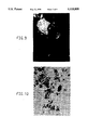
- FIG. 12--FIG. 12 is an optical photomicrograph at 600 ⁇ magnification of a portion of the product formed in accordance with Example 7B.
- FIG. 13--FIG. 13 is an elevational view of a section of a plasma display panel.
- the present invention relates to a cost efficient luminescent composition
- a cost efficient luminescent composition comprising particles of an inert core material the surface of which has been at least partially coated with a luminescent material in the form of a substantially chemically homogeneous coating.
- the average diameter of the core particle typically ranges from about 0.5 to at least about 20 microns, normally about 1.0 to about 10 microns, and the coating corresponds to between about 2 to about 30 wt % of the total composition.
- the invention relates to a process for preparing the luminescent composition which comprises decomposing a solution of chelated metal luminescent precursors at high pH while in the presence of dispersed inert core particles wherein at least a portion of the particles become coated with hydrous metal oxides, recovering the coated particles, normally washing the particles substantially free from soluble species, drying; and calcining.
- a hydrous oxide coating upon the core particles is substantially converted to a sulfide coating by being treated with a source of active sulfur.
- the source of active sulfur can comprise at least one water soluble member from the group of sodium sulfide, potassium sulfide, ammonium sulfide, mixtures thereof, among others.
- the invention is a process comprising preparing an acidic solution of at least one metal oxide along with a solution of an oxalic acid, adding the solutions to a slurry of dispersed particles wherein at least a portion of the particles become coated with metal oxalates, recovering the oxalate coated particles, washing the particles substantially free from soluble species, drying the oxalate composition, and calcining to form and activate the luminescent material.
- activate it is meant that at least a portion of the coated particles, e.g., a calcined coating upon the particle, becomes luminescent when excited by a suitable energy source.
- a luminescent composition can be obtained by dry or wet mixing core particles with metal oxalate powders and/or bulk phosphor powders, and calcining the mixed powders.
- the calcination temperature should be sufficient to cause 1) formation of a luminescent material coating over at least a portion of the core particle's surface, and; 2) activate the luminescent coating on the particle.
- the core particle may be coated by using an appropriate vapor deposition method.
- the core particles may be exposed to a vapor, which contains a precursor of a luminescent material, that is deposited upon at least a portion of the core particle's surface.
- a vapor precursor of the luminescent material may be passed through a chamber which contains the core particles.
- a volatile source e.g., a material that decomposes when heated, of the vapor precursor may be used for in situ generation of the vapor precursor. While any suitable vapor precursor of the luminescent material may be employed, for best results the vapor precursor should neither interact with the core particle nor adversely affect further processing of the coated core particle.
- the novel composition of the invention is a cost efficient luminescent composition
- a core material or particle typically having an average diameter in the range of from about 0.5 to about 20 microns; normally about 1.0 to about 10.0 microns.
- At least a portion of the surface of the core particle has been suitably coated with a luminescent material which is distributed about the particle in a substantially chemically homogeneous layer wherein the layer corresponds to about 2 through about 30 wt %, usually between 5 and 20 wt % of the total composition.
- the quantity of luminescent material should be sufficient to provide a R(I) spectrum which is substantially equivalent to conventional phosphor materials, e.g., the composition of the invention achieves about 50 to about 90% of the R(I) exhibited by conventional bulk phosphor materials.
- the luminescent material may comprise a layer of generally interconnected or dispersed luminescent crystallites.
- the composition of the luminescent coating is typically substantially homogeneous, the composition of at least a portion of an individual luminescent crystallite may deviate, e.g., the activator concentration may vary throughout a crystallite.
- the crystallite surface may be relatively rich in one or more activators, e.g., the Eu/Y ratio at the surface of an Eu:Y 2 O 3 crystallite may be greater than at the crystallite's center. An increased surface concentration of one or more activators on the crystallite may enhance the effectiveness of the luminescent composition.
- the luminescent composition of the invention is characterized by a relative luminescent intensity R(I).
- the R(I) of an emission peak is defined as the number of counts observed at the peak's maximum height divided by the number of counts measured at a reference detector from a split portion of the excitation intensity for a given spectrometer configuration.
- merely reporting the R(I) for a given phosphor, without more information, may be misleading because the R(I)s which are generated by a spectrometer typically are unique for that spectrometer.
- two different spectrometers, which have identical settings may produce two distinct R(I) spectrums for the same powder.
- a more useful R(I) can be obtained by generating the R(I) spectrum, for a powder being tested, opposite at least one standard reference phosphor of similar composition (refer to FIGS. 6, 8, and 11 which are discussed below in greater detail).
- the quantity of luminescent material and the activator concentration within the coating upon the core particles can be tailored in order to obtain a predetermined intensity.
- the quality of the luminescent coating may not be desirable at loadings above about 30 wt % of the total composition, e.g., such loadings may induce agglomeration of the luminescent material and/or the formation of fine particulate debris.
- the loading of coating material ranges from about 5 through about 20 wt % of the total composition which typically achieves the optimal combination of raw material cost and luminescent intensity. It will be appreciated, however, that this optimal loading will vary with 1) the size of the core particles, 2) the relative densities of the core and luminescent coating, 3) factors relating to the end use application, among other factors.
- the concentration of luminescent activator in the present coating may be greater than the concentration of such an activator throughout conventional bulk phosphors; however, the total weight of luminescent activator is normally less in the present composition than in conventional phosphors.
- the invention may obtain a composition comprising a calcined core particle, which has been coated with a quantity of at least one luminescent material, that is sufficient to obtain an R(I) that is at least about 60% of the luminescent material.
- the luminescent coating of the invention may include at least one activator such as a member selected from the group of rare earth elements such as cerium and terbium, tin II, antimony III, Cu, Ag, Mn, among others, and at least one suitable host material.
- a suitable host material may comprise at least one member from the group Y 2 O 3 , YVO 4 , Sr 2 P 2 O 7 , (Ca,Sr) 5 (F,Cl)(PO 4 ) 3 , ZnS, Y 2 O 2 S, MgAl 11 O 19 , BaMg 2 Al 16 O 27 , among others.
- the core particle is substantially inert.
- inert it is meant that the core particle substantially avoids reacting with the luminescent coating in a way that adversely impacts luminescence. Because many luminescent compositions are typically heated to temperatures greater than about 1000° C. in order to activate the luminescent material, it is particularly important that the core material be substantially stable and non-reactive at such temperatures. Relatively low levels of certain undesirable impurities can significantly diminish luminescence and, accordingly, for best results, the core composition should be substantially completely devoid of such impurities or such impurities are substantially prevented, if present, from being extracted into the luminescent layer.
- these undesirable impurities may cause poisoning, e.g., non-radiative energy transfer in the form of vibrational energy.
- Ions that have non-radiative transitions to their ground state, and which should be avoided in the preparation of the present composition include Fe 2 +, Co 2 +, Ni 2 +, Al +3 , Si +4 , among others.
- the sensitivity of a luminescent material to a poison varies inversely with the activator concentration, e.g., alkaline earth metals may poison certain luminescent materials.
- An s-center phosphor can typically tolerate about 100 times more of a given poison than an i-center phosphor.
- An s-center refers to a substitutional activator such as Eu substituting for Y in Eu:Y 2 O 3
- an i-center refers to an interstitial activator atom as is postulated to be the case for Cu activated ZnS.
- Any poisons that are present in the composition may reduce luminescence efficiency by:
- the suitability of the particles of core material can also be determined, in part, by the composition of the luminescent coating and the potential for an undesirable interaction between the two.
- the core material should not absorb light at the frequencies of interest, e.g., the activating radiation and emitted radiation. However, such absorption may be desirable when providing a plurality of coatings, and/or coatings containing more than one luminescent material, upon the core particles.
- the core should avoid adversely effecting any electrical processes which are associated with operating a light-emitting device.
- water-soluble core materials will be unsatisfactory for use in this invention; although such materials may be satisfactory for use in non-aqueous coating processes provided they are otherwise acceptable.
- normally unacceptable core particles can be rendered suitable for use in the invention by being coated with a substance which substantially counteracts or eliminates the unsatisfactory property.
- normally unacceptable particulate core materials can be rendered suitable for use in the invention by applying a coating of a suitable core material that would serve as an "inert" barrier between the core particle material and the luminescent coating.
- a core material, or a barrier coated core material is suitable for use in the present invention is dependent upon the particular luminescent material being coated upon the core material and, accordingly, for best results, the core material which is employed in the invention is one that is inert with respect to a specific luminescent coating.
- Suitable particulate core particles comprise at least one member selected from the group of alkaline earth sulfate, alkaline earth phosphate, metal silicate, metal oxides such as aluminum oxide, magnesium oxide (MgO), mixed metal oxides, alkaline earth fluoride, mixtures thereof, among others.
- core particles comprising one or more of BaSO 4 , CaO, CaF 2 and CaSO 4 .
- the core particles are usually essentially iso-dimensional, and typically have an average diameter between about 0.5 to 20 microns, and normally from about 1.0 to 10.0 microns. It is desirable for the core particles to be characterized by a relatively narrow particle size distribution and a small average particle size. For example, a desirable distribution is one wherein about 90% of the core particles have a diameter which ranges from about 0.1 D to 10.0 D ("D" is defined as the weight average particle diameter).
- D is defined as the weight average particle diameter.
- a narrow particle size distribution is particularly advantageous when employing the inventive composition as a luminescent material in fluorescent lamps, television screens, flat panel displays, among others. Without wishing to be bound by any theory or explanation it is believed that a narrow particle size distribution improves particle packing efficiency, and a small particle size reduces the amount of luminescent material necessary to effectively coat a substrate.
- Average particle size and particle size distribution can be determined by methods described in "Measurement of Suspended Particles by Quasi-Electric Light Scattering", E. B. Dahneke, Wiley Interscience, N.Y. 1983; which is hereby incorporated by reference. Particularly useful for performing these methods is the Microtrac II Small Particle Analyzer manufactured by Leeds Northrop and Company.
- the exterior surface of the core particle is coated with a substantially chemically homogeneous layer comprising a luminescent material which typically corresponds to between about 2 and 30 wt %, and normally about 5 to 20 wt % of the total composition.
- the coating materials may comprise at least one member selected from the (host:activator) group of (Y 2 O 3 :Eu), (Y 2 O 2 S:Eu), (YVO 4 :Eu), (La,Ce,Tb)(PO 4 ) 3 :(Ce,Tb), (Zn 2 SiO 4 :Mn), (BaMg 2 Al 16 O 27 :Eu), (SrB 4 O 7 :Eu), MgAl 11 O 19 :CeO. 65 TbO.
- coating materials are (Y 2 O 3 :Eu), (YVO 4 :Eu), (BaMg 2 Al 16 O 27 :Eu), (CeO. 65 TbO. 35 MgAl 11 O 19 ), (ZnS:Cu), (ZnS:Ag), and mixtures thereof e.g., these coating materials can be used in a number of commercial applications such as lamps, TV screens, flat panel displays such as plasma display panels, among others.
- the luminescent material is normally present as interconnected or dispersed crystallites about the surface of the core particles, whereas in some cases the core particles may be crystalline and/or amorphous.
- a composition of the invention may be prepared in a variety of ways.
- One process utilizes a chelate precursor of the luminescent components as a carrier to deposit the luminescent precursor as a hydrous metal oxide and/or metal oxide onto slurried core particles.
- a luminescent precursor is precipitated as an oxalate onto a slurry of core particles.
- the deposited hydrous metal oxide, oxalate among others, can be activated to form a luminescent coating upon the surface of the core particles.
- at least one of the components being deposited or precipitated onto the core particles is present within a solution comprising an acid, e.g., hydrochloric acid, wherein the luminescent precursor is deposited by increasing the pH.
- a luminescent composition can be obtained by dry or wet mixing previously coated and/or uncoated core particles with metal oxalate powders and/or bulk phosphor powders, and calcining the mixed powders.
- the calcination temperature should be sufficient to cause 1) formation of a luminescent material coating over at least a portion of the core particle's surface, and; 2) activate the coated particle.
- the calcination temperature ranges from about 700° to about 1,400° C., and normally 1,000° to 1,200° C.
- the core particle may be coated by using an appropriate vapor deposition method.
- the core particles may be exposed to a vapor, which contains a precursor of a luminescent material, that is deposited upon at least a portion of the core particle's surface.
- a vapor precursor of the luminescent material may be passed through a chamber which contains the core particles.
- a volatile source e.g., a material that decomposes when heated, of the vapor precursor may be used for in situ generation of the vapor precursor. While any suitable vapor precursor of the luminescent material may be employed, for best results the vapor precursor should neither interact with the core particle nor adversely affect further processing of the coated core particle.
- the luminescent precursor is deposited as a hydrous oxide onto at least a portion of the surface of slurried core particles.
- the hydrous oxide can be converted to a sulfide by exposure to a source of active sulfur, e.g., treatment with a solution comprising sulfur salts such as potassium, ammonium, and sodium sulfides.
- the treated hydrous oxide coating may be converted to a sulfide coating by being heated to a temperature of at least about 90° C.
- the sulfide coated particles can be isolated, washed to substantially remove soluble species, dried, e.g., at a temperature of about 120° C., and admixed with a second sodium salt such as sodium chloride, e.g., about 2 to 20 wt % dry NaCl is added to the dried sulfide coated particles.
- the sulfide coated particles may be washed for removing the second sodium salt.
- the core particle may be converted when exposed to relatively high temperatures, e.g., above about 900° C. or a calcination temperature sufficient to activate the luminescent material.
- a core particle can be converted or decomposed to form a metal oxide.
- Any suitable convertible core particle can be used which 1) possesses a conversion temperature lower than the luminescent material's activation temperature, and; 2) is inert or capable of being rendered inert.
- suitable core particles comprise at least one of CaCO 3 , MgCO 3 , among others.
- the luminescent compound can be deposited upon a convertible core particle in accordance with one or more of the previously described methods that is suitable for the selected core particle, and calcined.
- the convertible core particle becomes a metal oxide such as CaO, MgO, among others.
- a metal oxide such as CaO, MgO, among others.
- the metal oxide may be converted further as a result of being exposed, for example, to water and carbon dioxide in the atmosphere.
- the metal oxide may be converted to a hydroxide form, e.g., CaO can be converted to Ca(OH) 2 .
- the later conversion process may be useful for cementing or fixing the luminescent material to the core particle.
- a process of the present invention comprises the following steps:
- the above-identified slurry of core particles may be prepared with a fluid selected from mixtures of deionized water with at least one water miscible organic liquid which does not adversely interact with the core particles or the luminescent precursor coating.
- the water miscible organic fluid may be selected from at least one of C1-C4 branched or straight chain alcohols, glycols, mixtures thereof, among others.
- a solution comprising metal chelates of the luminescent precursor, at least one suitable chelate solvent, and at least one chelating agent is prepared.
- chelating agent it is intended to refer to one or more polydentate ligands whose structure permits the simultaneous attachment of two or more donor sites onto the same metal ion, thereby forming a closed ring structure.
- a "ligand” is defined as any atom, ion, or molecule which is capable of functioning as a donor partner in one or more coordinate bonds.
- Chelating agents useful in practicing the invention comprise at least one member from the group of alphahydroxycarboxylic acids, such as lactic, glycolic, malic and citric acid or alphaaminocarboxylic acids, such as ethylene diamine tetracetic acid (EDTA), glycine, mixtures thereof, among others.
- a solution of the chelating agent is prepared using a solvent, for example, deionized water or mixtures of deionized water with water miscible solvents such as methanol, ethanol, isopropanol, mixtures thereof, among others.
- the solvent may optionally contain small amounts of wetting agents or surfactants for enhancing dissolution of the metal compounds.
- the quantity of chelating agent should be sufficient to create a solution comprising metal chelates.
- the appropriate metal compound(s) can be stirred into the above described chelating agent and solvent solution.
- the metal compounds comprise the general formula, MXn, wherein "M” is a metal cation comprising at least one member selected from the group of magnesium, aluminum, zinc, copper, silver, calcium, strontium, barium, antimony, manganese, vanadium, tantalum, tungsten, yttrium, lanthanum, terbium, europium, lutetium, mixtures thereof, among others; wherein "X” is an anion or a radical selected from HCO 2 --, CH 3 CO 2 --, --OH, --OR, --NO 3 and --Cl, mixtures thereof, among others; and "n” is a whole number which ranges from 1 through 6 and is a function of the valence state of the metal cation M +n .
- Certain metal oxides which are soluble in mineral acids, may also be used as a source of the metal cation, e.g., Y 2 O 3 , Eu 2 O 3 , ZnO, Sb 2 O 3 , V 2 O 5 , mixtures thereof, among others.
- the pH of the previously described solution is adjusted to a value which ranges from about 5 through at least about 10; typically by adding a strong base selected from ammonium hydroxide, tetramethyl-ammonium hydroxide, sodium hydroxide, potassium hydroxide, mixtures thereof, among others.
- a pH between 5 to 8 is suitable for obtaining a stable solution of metal chelates.
- the solution pH is a key factor which determines whether or not a stable solution of metal chelates is obtained, other important factors include the metal compound, valence state of the metal compound, chelating agent, among other factors.
- the chelating agent is capable of forming soluble chelates with metal cations which were provided by the metal compound.
- the metal compounds be substantially completely dissolved in the solution, and that the quantity of chelating agent be sufficient to accomplish substantially complete dissolution.
- a relatively clear solution is obtained by adding the chelating agent after introducing the metal compounds to the solution.
- the pH of the slurry can be increased to greater than about 9, typically above about 10, by adding a strong base, e.g., potassium hydroxide and/or sodium hydroxide.
- the slurry may be heated to a temperature in the range between about 50° C. to reflux, and maintained for a period of up to about 8 hours, typically for at least 4 hours, in order to decompose the metal chelates, thereby depositing a generally chemically homogeneous coating of the luminescent precursor material upon the surface of the core particles.
- Ammonium hydroxide may also be employed as a base. If ammonium hydroxide is employed, then a relatively high temperature may be required to decompose the metal chelates.
- decomposition can be accomplished by heating the slurry of core particles in an autoclave at a temperature of from about 100° C. to at least about 200° C.
- sodium hydroxide employed for converting the metal chelate to form a corresponding hydrous metal oxides and/or metal oxides
- the conversion can be illustrated by the following equation: ##STR1## wherein, for example, lactic acid R is CH 3 --, or for example, malic acid R is --CH2COO - Na + .
- hydrous metal oxides and/or metal oxides of a luminescent precursor can be deposited upon at least a portion of the surface of the core particles.
- the coated core particles can be recovered by filtration or centrifugation, and normally washed several times with deionized water to substantially remove any soluble organic or inorganic materials, if any, and dried in an air or vacuum oven.
- the dried coated powder can then be calcined at a temperature, for example, in the range of about 700° to 1,400° C., normally about 1,000° to 1,200° C., which is sufficient to activate the coating of luminescent precursor.
- a temperature for example, in the range of about 700° to 1,400° C., normally about 1,000° to 1,200° C., which is sufficient to activate the coating of luminescent precursor.
- the luminescent material is crystalline, e.g., the luminescent coating comprises interconnected or dispersed crystallites upon the surface of the core material.
- the optimum calcination temperature for activating the luminescent precursor and thereby form the luminescent material may require operation within an oxidizing, a reducing or an inert environment.
- the specific calcination conditions are selected in order to optimize luminescent intensity and particle size distribution.
- the R(I) of the luminescent material is normally a function of the calcining temperature.
- the calcining step can be used for tailoring the characteristics of the inventive composition.
- the core particles e.g., BaSO 4
- optionally mill the calcined particles e.g., the calcined particles may be hammer milled or ball milled.
- the calcined particles are then ready to be coated with a luminescent precursor. Calcination and milling produces a final product which possesses a relatively narrow particle size distribution (PSD), and reduces the average particle size.
- PSD particle size distribution
- a calcined/milled BaSO 4 core particle which is acid washed by slurrying in a mineral acid, e.g. HCl, to substantially remove undesirable acid soluble species, may achieve a conductance of less than about 50 umhos, resulting in an enhanced R(I) for the subsequent coated luminescent phosphor composition.
- a mineral acid e.g. HCl
- the composition of the coated powders can be determined by using x-ray fluorescence analysis, or inductively coupled plasma (ICP) analysis.
- the crystalline phase core material or the luminescent coating may be determined by x-ray diffraction analysis.
- the characteristics of the surface coating may be ascertained by optical microscopy, transmission electron microscopy (TEM) and energy dispersive spectroscopy (EDS). Surface areas can be determined by single point B.E.T. on a Micromeritics Flowsorb II 2300, and particle size can be determined on a Microtrac II Small Particle Analyzer.
- the relative intensity, R(I) of the coated core material can be measured using an SLM-8000 fluorescent spectrometer.
- the relative intensity can be measured by loading the coated particles into a quartz cuvette, and centering in the sample holder of the instrument.
- the excitation wavelength which is typically used to excite most photoluminescent compositions in a fluorescent lamp, is about 254 nm, which is the primary wavelength emitted by a mercury vapor discharge lamp. In a fluorescent spectrometer, the excitation wavelength is typically generated by a xenon lamp and a double-grating excitation monochromator.
- the R(I) of each sample is measured four times, one measurement for each face of the quartz cuvette, and the average value is calculated, i.e., an average value minimizes any systematic error caused by the sample holders.
- a bulk composition such as Y 2 O 3 :5 mole % Eu, which was prepared by the oxalate process described above, can be used as a standard.
- the spectrometer Prior to measuring the R(I) of the coated particles, the spectrometer is configured to give an R(I) value of about 2.1 for this standard.
- the invention covers a plurality of luminescent coatings, e.g., the luminescent material may comprise a plurality of, for example, successive coatings that absorb and/or emit the same and/or different colors.
- a previously coated core particle can be coated further to obtain a composition which emits light having certain characteristics, e.g., a core particle having a red-emitting phosphor coating is coated again with a green-emitting phosphor.
- the invention may be employed to provide a mixed composition luminescent coating, e.g., a coating comprising at least one layer which includes a plurality of luminescent materials.
- a composition of the invention can be modified by being coated with silica, thereby minimizing any reaction of the composition after the composition has been placed into service, e.g., used as a phosphor in a fluorescent lamp.
- This Example describes a method for making a phosphor containing barium sulfate coated with approximately 2.04 wt % Eu 2 O 3 and 24.86 wt % Y 2 O 3 based on the phosphor by using a chelate process.
- Deionized water about 540 ml
- approximately 31.4 g (0.2318 mole) of D,L-malic acid were charged to a 2-liter flask under a nitrogen atmosphere at a temperature of about 23° C.
- a solution comprising yttrium oxide in aqueous hydrochloric acid about 125.4 g, 19.84% Y 2 O 3 ; 22.69% HCl
- a solution of europium oxide in aqueous hydrochloric acid about 10.46 g, 19.49% Eu 2 O 3 ; 20.83% HCl
- a sodium hydroxide solution (approximately 119.4 g, 30% NaOH, 0.8955 mole) was added to the previously described solution in a dropwise fashion over a period of about 35 minutes while maintaining a temperature of about 25° C.
- the resultant solution which was generally colorless and had a pH of about 9.2, was diluted to about 1200 g by adding deionized water.
- the diluted colorless solution was combined with a slurry of about 73.1 g of barium sulfate (known as Blanc Fixe Micro Grade, a precipitated barium sulfate supplied by Sachtleben Corp.), in about 300 g of deionized water.
- the barium sulfate for this example had a surface area of about 2.6 m2/g.
- the resultant mixture was agitated overnight.
- aqueous sodium hydroxide solution about 21.1 g, 30% NaOH, 0.1583 mole
- the white slurry which had a pH of about 11.4, was then heated under reflux, to about 100° C. for 6 hrs.
- FIG. 1 is an optical photomicrograph at 600 ⁇ magnification of the commercially available phosphor which was used as the reference standard for the R(I) data summarized above.
- the commercially available material corresponds to a bulk phosphor powder comprising Y 2 O 3 doped with approximately 5 wt. % Eu 2 O 3 , supplied by GTE, which is sold under the trademark "Sylvania Type 2340".
- FIG. 2 is an optical photomicrograph at 600 ⁇ magnification of a portion of the powder formed in accordance with Example 1
- FIG. 3 is an optical photomicrograph at 1,000 ⁇ magnification of the powder shown in FIG. 2.
- FIG. 3 was taken with the above-identified microscope by using a 100 ⁇ oil immersion lens that was immersed into a drop of oil that had been placed on top of the cover glass.
- FIG. 1 shows a conventional bulk phosphor powder that has a particle size which ranges from approximately 2 to 15 microns.
- FIGS. 2 and 3 show BaSO 4 particles, which range in size from about 3 to 20 microns, that are coated with Eu:Y 2 O 3 phosphor crystallites.
- the generally clear outline of the particles shown in FIGS. 2 and 3 corresponds to BaSO 4 , whereas the relatively dark spots are crystallites of Eu:Y 2 O 3 which were coated on the surface of the BaSO 4 particles.
- This example describes a method for making phosphor containing barium sulfate coated with approximately 0.76 wt % Eu 2 O 3 and 9.24 wt % Y 2 O 3 based on the phosphor using a chelate process.
- Deionized water about 270 ml
- approximately 20.4 g (0.1507 mole) of D,L-malic acid were charged to a 1-liter flask under a nitrogen atmosphere while maintaining a temperature of about 25° C.
- a solution of yttrium oxide in aqueous hydrochloric acid approximately 62.2 g, 20% Y 2 O 3 ; 22.57% HCl
- a solution of europium oxide in aqueous hydrochloric acid approximately 5.1 g, 20% Eu 2 O 3 ; 20.72% HCl
- aqueous ammonium hydroxide solution (approximately 33.2 g, 29.2% NH 3 , 0.5692 mole), was added dropwise over a period of about 40 min while maintaining a temperature of about 25° C.
- a generally colorless solution was produced, which had a pH of about 8.0, and was diluted to about 600 g by the addition of deionized water.
- Barium sulfate (approximately 90 g) was slurried in 500 g of deionized water (the barium sulfate was known as Blanc Fixe Micro Grade a precipitated barium sulfate that was supplied by Sachtleben Corp., which had been calcined previously at about 900° C. for 1 hr and hammer-milled by using a Brinkmann Mill).
- Aqueous ammonium hydroxide (about 40 g, 29.2% NH 3 ) was added to the sulfate slurry while maintaining a temperature of about 25° C., and agitating the slurry. Agitation of the slurry was continued overnight.
- the slurry was heated to about 91° C., and about 446.1 g of the above-described colorless yttrium-europium chelate solution was added to the slurry over a period of about 2.5 hrs. The slurry was heated further under reflux to about 106° C. for 6 hrs.
- a white slurry was obtained which had a pH of about 8.6.
- the white slurry was filtered, and the filter cake washed with 16 liters of deionized water.
- the filter cake was dried to produce about 107.8 g of a white solid having a surface area of about 1.3 m2/g, and a particle size distribution of: D90, 8.49 ⁇ m; D50, 3.00 ⁇ m; and D10, 0.94 ⁇ m.
- a portion of the solid was pulverized by hammer milling, and calcined in air at a temperature of about 1200° C. for 1 hr.
- the resulting white powder had a surface area of about 0.6 m2/g, and a particle size distribution of: D90, 18.1 ⁇ m; D50, 7.13 ⁇ m; and D10, 1.62 ⁇ m.
- FIG. 4 is an optical photomicrograph at 600 ⁇ of a portion of the powder formed in accordance with Example 2.
- FIG. 4 illustrates a coating of relatively small phosphor crystallites upon the BaSO 4 particles.
- This example describes a method for making a phosphor containing barium sulfate coated with approximately 0.76 wt % Eu 2 O 3 and 9.24 wt % Y 2 O 3 based on the phosphor using an oxalate process.
- Barium sulfate (approximately 90 g) was slurried into 1500 ml of deionized water, and the slurry was agitated at a temperature of about 25° C. for 2 days.
- the barium sulfate was known as Blanc Fixe Micro Grade which is a precipitated barium sulfate supplied by Sachtleben Corp.) The slurry was heated to about 91° C.
- a solution was prepared by combining solutions of yttrium oxide in aqueous hydrochloric acid (approximately 46.2 g, 20% Y 2 O 3 ; 22.57% HCl), and europium oxide in aqueous hydrochloric acid (approximately 3.79 g, 20% Eu 2 O 3 ; 20.72% HCl), with about 50 ml deionized water which had a temperature of about 25° C.
- a second solution was prepared by dissolving about 17.9 g (0.1422 mole) of oxalic acid dehydrate into about 46 ml of deionized water which had a temperature of about 60° C.
- the barium sulfate slurry was heated to about 91° C., and the two previously described solutions were added simultaneously to the sulfate slurry over a period of about 2 hrs.
- the resulting slurry was heated further under reflux to a temperature of about 102° C. which was maintained for about 6 hrs.
- FIG. 5 is an optical photomicrograph at 1,000 ⁇ magnification of a portion of the powder formed in accordance with Example 3.
- FIG. 5 shows one BaSO 4 particle which essentially has no coated phosphor crystallites, and another adjacent particle that is substantially completely coated with phosphor crystallites.
- FIG. 6 is a graphical representation of the R(I) spectrums in terms of emission wavelength (x-axis) and R(I) (y-axis), for the conventional powder shown in FIG. 1, and powders which were formed in accordance with Examples 1-3.
- Curves "A” through “C” of FIG. 6 correspond, respectively, to R(I) spectrums which were emitted by powders which were formed by Examples 1-3, and Curve “D” corresponds to a R(I) for the commercial phosphor shown in FIG. 1.
- Increment 0.2 ⁇ m
- Integration Time 0.1 sec
- High Voltage B 505.
- Curves A-D illustrates that the powders of the present invention are capable of achieving R(I) values approximately 65 to 70% of conventional bulk phosphor powders, while using a significantly less total amount of luminescent material
- This example describes a method of making a phosphor containing barium sulfate coated with approximately 0.38 wt % Eu and 9.62 wt % YVO 4 based on the phosphor.
- D,L-Malic acid (approximately 7.67 g ,0.0566 mole) was dissolved in a solution of about 15.7 g of 37% hydrochloric acid and 2.4 g of deionized water. The solution was heated to about 45° C., and about 5.16 g(0.0283 mole) of vanadium pentoxide (99.9% V 2 O 5 ) was added to the solution over a period of about 1 hr., while maintaining a temperature of about 45°-70° C., thereby producing a dark blue solution.
- D,L- malic acid (approximately 10.5 g, 0.0775 mole) was dissolved in 200 g of deionized water.
- a solution of yttrium oxide in aqueous hydrochloric acid (approximately 31.9 g, 20% Y 2 O 3 ; 22.57% HCl), and a solution of europium oxide in aqueous hydrochloric acid (approximately 2.62 g, 20% Eu 2 O 3 ; 20.72% HCl), were added to the malic acid solution while being agitated and maintaining a temperature of about 25° C.
- the previously described blue vanadium solution was poured into the agitated solution along with about 40 g of deionized water.
- a sodium hydroxide solution (approximately 65.1 g, 30% NaOH; 0.4883 mole), was also added to the agitated solution in a dropwise manner while maintaining a temperature of about 25° C.
- a greenish black chelate solution which had a pH of about 8.0, was obtained, that was in turn diluted to about 600 g by adding deionized water.
- a portion of the greenish black chelate solution (approximately 500 g) was added to a slurry comprising about 90 g of barium sulfate particles (known as "F" Grade, a precipitated barium sulfate supplied by Sachtleben Corp., which had been calcined previously at 700° C. and treated with 10% hydrochloric acid), into 500 g of deionized water.
- a sodium hydroxide solution (approximately 23.3 g, 30% NaOH; 0.1748 mole), was added to the slurry while maintaining a temperature of about 25° C. over a period of about 30 min.
- the slurry which had a pH of about 11.8, was heated further under reflux to a temperature of about 101° C.
- a tan colored slurry was obtained, which had a pH of about 12.2, that was filtered and the filter cake washed with 10 liter of deionized water.
- the filter cake was dried at a temperature of about 120° C. to produce about 100 g of a cream colored solid having a surface area of about 17.7 m2/g. A portion of the solid was calcined at about 1,100° C. for 30 minutes to produce a light yellow powder.
- FIG. 7 is an optical photomicrograph at 1,000 ⁇ magnification of a portion of the powder formed according to Example 4.
- FIG. 7 shows a variety of different sized particles of BaSO 4 , which have unequal amounts of Eu:YVO 4 phosphor crystallites deposited thereon.
- FIG. 8 is a graphical representation of the R(I) spectrums, in terms of emission wavelength (x-axis) and R(I) (y-axis), for a portion of the powder formed in accordance with Example 4, and a commercially available powder comprising YVO 4 containing approximately 4 wt. % Eu 2 O 3 , which was supplied by GTE, under the trademark "Sylvania Type 2390".
- Curve "E” corresponds to the R(I) emitted by the powder of Example 4
- Curve “F” corresponds to the R(I) emitted by the Sylvania Type 2390 powder.
- the R(I) was generated by using a SLM-8000 spectrometer, which used settings corresponding substantially to those set forth in Example 3.
- FIG. 8 shows that the powder formed according to Example 4 is capable of emitting a R(I) which is about 45 to 60% of commercially available phosphor materials.
- This example describes a procedure for making a Y 2 O 3 :Eu phosphor composition coated onto a BaSO 4 substrate by a dry powder process.
- the two substantially dry powders which are employed in this example comprise BaSO 4 (supplied by Sachtleben Corp. Blanc Fixe Micro Grade), which had been calcined previously at about 900° C. for one hour and then hammer milled, and a europium doped yttrium oxalate powder that was formed substantially in accordance with the oxalate process described in Example 3; except that the oxalate powder was not deposited upon a core material.
- This Example describes preparing a phosphor of barium sulfate particles that were coated with about 1.48 wt % Eu 2 O 3 and 8.52 wt % Y 2 O 3 based on the phosphor which was obtained by using an oxalate process.
- the barium sulfate particles which were used in this example are Blanc Fixe N Grade (a precipitated barium sulfate supplied by Sachtleben Corp.).
- the barium sulfate was treated prior to coating by being calcined at a temperature of about 700° C. for 1 hr., and hammer milled.
- the calcined barium sulfate was slurried into about 4% aqueous hydrochloric acid at a temperature of about 60° C. for about 1 hr, followed by washing with deionized water, and drying at a temperature of about 100° C.
- a sample of the dried barium sulfate (about 90 g) was slurried into about 1500 ml of deionized water, and the slurry was agitated overnight while maintaining a temperature of about 25° C. The slurry was then heated to about 90° C.
- a first solution was prepared by combining a solution of yttrium oxide in aqueous hydrochloric acid (approximately 42.6 g, 20% Y 2 O 3 ; 22.57% HCl), a solution of europium oxide in aqueous hydrochloric acid (approximately 7.38 g, 20% Eu 2 O 3 ; 20.72% HCl) with about 50 g of deionized water at a temperature of about 25° C.
- a second solution was prepared by dissolving about 17.3 g (0.1384 mole) oxalic acid dehydrate into 46 g of deionized water at about 60° C.
- the first and second solutions were added simultaneously to the previously described barium sulfate slurry over a period of about 2 hrs while maintaining the temperature of the reaction mixture at about 90° C.
- the resulting white slurry was heated under reflux (102° C.) for about 6 hrs.
- the white slurry was filtered, and the filter cake was washed with about 4 liters of deionized water.
- the filter cake was dried at a temperature of about 120° C., thereby forming about 108.9 g of a white solid having a surface area of about 1.2 m2/g, and a particle size distribution of: D90, 9.24 ⁇ m; D50, 4.99 ⁇ m; and D10, 1.96 ⁇ m.
- a portion of the dried white powder was calcined in air at a temperature of about 1200° C. for 10 min., which produced another white powder with a surface area of about 0.32 m2/g, and a particle size distribution of: D90, 28.9 ⁇ m; D50, 9.91 ⁇ m; and D10, 2.21 ⁇ m.
- FIG. 9 is an optical photomicrograph at 600 ⁇ magnification taken under crossed-nicols, and with an immersion oil, which has a refractive index of 1.64, of a powder formed according to Example 6.
- FIG. 9 shows two major BaSO 4 particles, which are birefringant, and appear bright white on a black background.
- the relatively large particle possesses a less dense coating of Eu:Y 2 O 3 phosphor crystals, whereas the density of Eu:Y 2 O 3 phosphor crystallites is greater on the smaller particle.
- FIG. 10 is an optical photomicrograph of the same powder shown in FIG. 9, with the exception that FIG. 10 was taken without the crossed-nicols. Because the refractive index of the immersion oil is substantially equivalent to the refractive index of BaSO 4 , the BaSO 4 particles were essentially invisible in FIG. 10, and only the relatively small and dark phosphor crystallites are clearly visible. The phosphor crystallites are more easily seen in FIG. 10 because the refractive index of Eu:Y 2 O 3 is much greater than 1.64.
- FIG. 11 is a graphical representation, in terms of emission wavelength (x-axis) and R(I) (y-axis), of the powder shown in FIGS. 9 and 10, as well as the commercially available powder shown in FIG. 1.
- Curve “H” on FIG. 11 corresponds to the emitted R(I) for the powder shown in FIG. 1
- Curve “G” corresponds to the emitted R(I) for the powder made in accordance with Example 6.
- the R(I) was generated by using a SLM-8000 spectrometer which was operated substantially at the settings set forth in Example 3.
- composition of the invention is capable of achieving a peak R(I) value, i.e., about 2.0, which is commensurate with commercially available phosphors.
- a luminescent composition of the invention was prepared substantially in accordance with Example 1 which comprised a coating of about 5 mole % Eu:Y 2 O 3 upon the BaSO 4 powder.
- the coating corresponded to about 20% by weight of the total phosphor coated product.
- the phosphor coated product of the invention After being calcined at a temperature of about 1,100° C. in air for a period of about 4 hours, the phosphor coated product of the invention had a peak R(I) of about 1.57. Based upon the measured R(I) intensities, the calcined inventive composition can employ an equivalent weight of phosphor as the dry mechanical mixture and yet achieve superior intensities.
- This part of the Example illustrates calcining and acid treating BaSO 4 which was used in a dry mechanical mixture of BaSO 4 and Eu:Y 2 O 3 .
- a mechanical mixture was prepared using approximately 3.6 grams of the acid washed BaSO 4 and about 0.4 grams of commercially available Eu:Y 2 O 3 powder (Supplied by GTE as 2340). The mixture was obtained by rolling the two powders together in a small glass vial for about 5 minutes. The measured R(I) for the mixture, which corresponded to an about 10 wt % Eu:Y 2 O 3 blend, was about 0.65. This is a significant improvement over the 20 wt % Eu:Y 2 O 3 blend described in Example 7A wherein the R(I) was about 0.54. This part of the Example demonstrates that a calcined and acid washed core particle can achieve a higher R(I) while employing about one-half the amount of Eu:Y 2 O 3 phosphor.
- FIG. 12 is an optical micrograph that was taken at 600 ⁇ magnification show that the larger Eu:Y 2 O 3 crystallites are present as agglomerates or individual particles whereas the relatively smaller crystallites (those less than about 2 microns) are embedded onto the surface of the BaSO 4 particles.
- the coating characteristics range from substantially no crystallites on the relatively small BaSO 4 particles to a spotty or random crystallite coating on the larger BaSO 4 particles.
- the luminescent material is already activated crystallites, and the calcination step is used for improving R(I).
- This example describes a method for making a luminescent composition comprising barium sulfate coated with approximately 2.04 wt % Eu 2 O 3 and 24.86 wt % Y 2 O 3 based on the phosphor.
- Barium sulfate (approximately 73 g) was slurried in about 1500 ml of deionized water, and the slurry was agitated at about 25° C. overnight in a nitrogen atmosphere.
- the barium sulfate for this experiment was Blanc Fixe Micro Grade, a precipitated barium sulfate supplied by Sachtleben Corp.
- the barium sulfate slurry was warmed to a temperature about 90° to 95° C.
- a solution comprising yttrium oxide in aqueous hydrochloric acid (about 125.3 g, 19.48% Y 2 O 3 ; 22.69% HCl) and europium oxide in aqueous hydrochloric acid (about 10.46 g, 19.49% Eu 2 O 3 ; 20.83% HCl) was prepared.
- This solution was added simultaneously with about 82.5 g (0.6189 mole) of 30% aqueous sodium hydroxide solution to the barium sulfate slurry while maintaining the pH of the slurry at about 8.0 to 8.5.
- the resultant white slurry which had a pH of about 8.2, was heated under reflux to about 100° C. for about 6 hrs.
- the R(I) of a sample of the powder was determined substantially in accordance with the procedure discussed above, and a peak with an intensity of about 1.09 was measured.
- the other half of the slurry was filtered and washed with about 15,000 ml of deionized water.
- the filter cake was dried at a temperature of about 120° C., thereby producing about 50.8 g of a white solid having a surface area of about 17.2 m2/g.
- a portion of the white solid was ground in a mortar and pestle, and calcined in air at a temperature of about 1,100° C.
- the R(I) of a sample of the powder was measured, and determined to be about 1.05.
- This example describes a method for making a luminescent composition comprising barium sulfate coated with approximately 1.48 wt % Eu 2 O 3 and 8.52 wt % Y 2 O 3 based on the phosphor.
- Deionized water about 270 ml
- approximately 29.6 g (0.2181 mole) of D,L- malic acid were charged to a 1-liter flask under a nitrogen atmosphere and maintained at a temperature of about 25° C.
- a chelate solution comprising yttrium oxide in aqueous hydrochloric acid (about 85.2 g, 20% Y 2 O 3 ; 22.57% HCl) and a solution of europium oxide in aqueous hydrochloric acid (about 14.8 g, 20% Eu 2 O 3 ; 20.72% HCl) were added to the 1-flask while being agitated.
- the resulting substantially clear solution was allowed to agitate at about 25° C. for about 15 min.
- Aqueous potassium hydroxide solution (about 146.4 g, 30% KOH, 0.7827 mole) was added to the solution in a dropwise fashion over a period of about 40 minutes while maintaining a temperature of about 25° C.
- the resultant solution which was substantially colorless, had a pH of about 8.0 and was diluted to about 600 g with deionized water.
- Barium sulfate (about 87 g) was slurried in about 483 g of deionized water and maintained in a nitrogen atmosphere at about 25° C.
- the barium sulfate was Blanc Fixe Micro Grade from Sachtleben Corp., which had been calcined at about 800° C. for 1 hr with about 30% potassium chloride, extracted with 10% hydrochloric acid, washed with deionized water and dried.
- An aqueous potassium hydroxide solution (about 21.7 g, 30% KOH, 0.12 mole) was added to the slurry of barium sulfate.
- a portion (14.5 g) of the above described yttrium-europium chelate solution was added to the slurry over a period of about 2 hrs. at a temperature of about 25° C.
- the slurry was agitated for about two days.
- the slurry was warmed to a temperature of about 91° C., and then about 275.5 g of the yttria-europia chelate solution was added over a period of about 75 minutes.
- the resultant white slurry was heated further under reflux at about 101° C. for about 6 hrs.
- a white slurry was obtained which had a pH of about 12.1.
- the slurry was filtered, and the filter cake washed with about 17 liters of deionized water.
- the filter cake was dried to produce about 99 g of a white solid having a surface area of about 12.7 m2/g, and a particle size distribution of: D90, 9.39 ⁇ m; D50, 5.99 ⁇ m; D10, 4.06 ⁇ m.
- the white solid was calcined in air at a temperature of about 1200° C. for about 30 minutes.
- the resultant white powder had a surface area of about 0.75 m2/g, and a particle size distribution of: D90, 10.8 ⁇ m; D50, 6.28 ⁇ m; D10, 3.05 ⁇ m.
- the R(I) of a sample of the powder was measured substantially in accordance with the method discussed above, and was determined to be about 1.14.
- the Example described above was repeated with the exception that all operations were carried out in an air atmosphere instead of nitrogen.
- the R(I) of the of the resulting white powder was determined to be about 1.41.
- This example describes a procedure for making a Eu:Y 2 O 3 luminescent composition coated onto a CaO substrate.
- the two raw material sources were a CaCO 3 (supplied by J. T. Baker), and a europium doped yttrium oxalate powder.
- CaCO 3 supplied by J. T. Baker
- europium doped yttrium oxalate powder About one gram of CaCO 3 was dry mixed together with about 0.15 g of europium doped yttrium oxalate (5 mole % Eu 2 O 3 ), and then calcined in air at a temperature of about 1150° C. for a period of about 30 minutes.
- the calcined composition comprised about Eu(5):Y 2 O 3 /CaO(93) which indicates the formation of an approximately 7 wt. % coating of a 5 mole % europia doped yttria on CaO.
- CaCO 3 converts or decomposes to CaO and CO 2 .
- the core particles comprised CaO. It is also believed that when the CaO core particles are exposed to air, at least a portion of the CaO will convert to Ca(OH) 2 and in turn partially form CaCO 3 .
- the R(I) of this composition was measured by using the previously described method, and determined to be about 0.9.
- This example describes a procedure for making a Eu:Y 2 O 3 luminescent composition coated onto a CaO core particle.
- the two raw material sources were a europium doped yttrium oxalate powder and a CaCO 3 (supplied by J. T. Baker), which had been calcined at a temperature of about 900° C. for a period of about one hour. After calcining the CaCO 3 , it is believed that a majority of the CaCO 3 converted or decomposed, and formed CaO with trace amounts of Ca(OH) 2 and CaCO 3 .
- the resultant composition comprised approximately Eu(5):Y 2 O 3 /CaO(89) which indicates that an approximately 11 wt. % coating of a 5 mole % europia doped yttria was formed on CaO.
- This example describes a procedure for making a Eu:Y 2 O 3 phosphor composition coated onto an MgO substrate.
- the two raw material sources comprised MgO (supplied by Alpha Company), and a europium doped yttrium oxalate powder.
- MgO supplied by Alpha Company
- a europium doped yttrium oxalate powder Approximately 0.8 grams of MgO was wet mixed together with about 0.2 g of europia doped yttrium oxalate (approximately 5 mole % Eu 2 O 3 ).
- the oxalate was prepared substantially in accordance with the method described above in Example 3. The materials were wet mixed using about 5 to 10 grams of deionized water and shaking in a small glass vial for about 5 minutes. The mixture was then poured into an alumina boat and calcined at a temperature of about 1150° C. for 30 minutes.
- the calcined composition comprised about Eu(5):Y 2 O 3 /MgO(88.5).
- the composition corresponded to an approximately 11.5 wt % coating of a 5 mole % europia doped yttria upon a core particle comprising MgO.
- This example describes a procedure for making a two component phosphor that comprised a green phosphor particle, which has a red light-emitting phosphor coating, that emits visually perceived white light when illuminated with a suitable source of UV radiation.
- the two raw material sources comprised an europia doped yttrium oxalate (approximately 5 mole % Eu 2 O 3 ) powder and a commercial GTE 2291 green phosphor having the composition comprising (Ce,Tb)MgAl 11 O 19 .
- the oxalate component was prepared substantially in accordance with the method described above in Example 3. Approximately 1.6 grams of the oxalate was dry mixed with about 0.4 grams of the GTE 2291 powder by shaking them together in a glass vial for about 5 minutes.
- the powder mixture was placed into an alumina boat and calcined in air at a temperature of about 1150° C. for a period of about 30 minutes.
- the calcined mixture comprised approximately Eu(5):Y 2 O 3 /(Ce,Tb)MgAl 11 O 19 (32.4).
- the mixture corresponded to an approximately 67.6 wt % coating of a 5 mole % europia doped Yttria coated onto a core particle comprising (Ce,Tb)MgAl 11 O 19 .
- the luminescent properties of the calcined mixture were tested by using a commercially available hand held UV lamp which emitted short wavelength light.
- the calcined powder visually appeared white when illuminated with UV light from the hand held UV lamp.
- the particle size distribution of this powder was about 1.5/5/12 u (d10/d50/d90), whereas the PSD for the GTE 2291 powder was measured to be about 4.5/9/15 u.
- the measured R(I) of this sample was about 1.2 at 612 nm, which is the primary red emission line for Eu:Y 2 O 3 , and about 0.9 at 543 nm, which is the primary emission line for the GTE 2291 phosphor.
- This example illustrates a method for blending a red light emitting coated barium sulfate, Eu:Y 2 O 3 /BaSO 4 , with a green light-emitting phosphor powder for making a composite luminescent material that emits visually perceived white light when excited with short wavelength UV radiation.
- a Eu(10):Y 2 O 3 /BaSO 4 (90) powder was prepared substantially in accordance with the method described above in Example 3 and a calcined and acid washed barium sulfate core particle.
- the resultant powder had a measured R(I) of about 2.0. This powder served as the red component of the two powder blend.
- the green component comprised commercially available GTE 2291 (Ce,Tb):MgAl 11 O 19 .
- the dry blend which comprised approximately 1.8 grams of the red component and 0.2 grams of the green component, was prepared by shaking the two powders together in a glass vial for about 10 minutes.
- the resultant dry blend contained about 90 wt % of the red component which corresponds to about 1.35 wt % Eu 2 O 3 and 7.65 wt % Y 2 O 3 .
- the blend was observed visually to emit a white light when illuminated with short wavelength UV light from a hand held UV lamp.
- a second dry blend was made by using a commercially available GTE 2340 phosphor (Eu:Y 2 O 3 ) as the red component of the blend.
- the GTE 2340 sample was analyzed using ICP analysis and found to contain about 4.6 wt % Eu 2 O 3 and 95.4 wt % Y 2 O 3 .
- a blend comprising approximately 0.5 grams of the GTE green component and 1.5 grams of the GTE red component was prepared substantially in the manner described in part A of this Example.
- the blend comprised about 75 wt % of the red phosphor which corresponds to about 3.45 wt % Eu 2 O 3 and 71.55 wt % Y 2 O 3 .
- the resultant blend was observed visually while being exposed to short wavelength UV light, and determined to emit a white light substantially the same as that observed in Example 14A.
- This example illustrates that substantially the same white light can be emitted from a luminescent composition comprising red light emitting phosphor coated powder, Eu(10):Y 2 O 3 /BaSO 4 (90), instead of bulk Eu:Y 2 O 3 powder.
- the luminescent composition of this Example requires significantly less total amounts of Eu 2 O 3 and Y 2 O 3 such that using the coated powder of this Example realizes a marked phosphor cost reduction. Additional cost savings are realized because about 15 wt % less of the green phosphor, which contains Tb 2 O 3 , was used in this part of the Example.
- This example describes a composition comprising Eu:Y 2 O 3 coated onto CaO particles that exhibited cathodoluminescent properties.
- An Eu(10):Y 2 O 3 /CaO luminescent composition was prepared substantially in accordance with the method described in Example 11 with the exception that a 10 mole % europia doped yttrium oxalate powder, which was made substantially in accordance with the oxalate process described in Example 3, were used as starting materials.
- a 10 mole % europia doped yttrium oxalate powder which was made substantially in accordance with the oxalate process described in Example 3, were used as starting materials.
- Approximately 0.8 grams of the CaO, 0.2 grams of the europium doped yttrium oxalate, and 5 ml of deionized water were slurried together in a small glass vial by rolling for about 5 minutes.
- the slurry was poured into an alumina boat and calcined at a temperature of about 1200° C. for 30 minutes.
- the final composition corresponded approximately to Eu(10):Y 2 O 3 /
- a sample of the previously described powder and a commercially available phosphor (GTE 2340 Eu:Y 2 O 3 ) powder were each placed separately into a 1 inch square stainless steel die and pressed at about 8 tons for 2 minutes in a "Wabash" press. The pressed powders were then used for determining whether or not each powder possessed cathodoluminescence.
- the pressed powder samples were individually mounted onto a pedestal, and placed within a Philips 515 Scanning Electron Microscope. Each sample was scanned using an electron beam which was set at 25 kV, 400 uA, and a 100 nm spot size.
- the cathodoluminescence detectors inside the Microscope are capable of detecting light between about 300 and 650 nm.
- Black and white photos of the electron beam-scanned samples were used to qualitatively assess the comparative cathodoluminescent efficiency of the samples.
- the degree of whiteness on the photo which is believed to correlate directly with the red luminescent emission, e.g., about 611 nm for Eu:Y 2 O 3 , were observed visually to be substantially equivalent.
- This example describes a phosphor composition comprising europium doped Y 2 O 3 coated onto a fluorite, CaF 2 , core particle.
- a dry mechanical mixture was made using about 3.2 grams of the calcined fluorite and approximately 0.8 grams of a bulk oxalate having an approximate composition comprising (Eu[10],Y) 2 (C 2 O 4 ) 3 , wherein the [10] refers to 10 mole %.
- the bulk oxalate was prepared substantially in accordance with the method described above in Example 3. The two powders were dry mixed in a glass vial by rolling them together for about 15 minutes. The mixed powders were placed into an alumina boat and calcined in air at a temperature of about 1100° C. for one hour.
- composition of calcined product comprised approximately Eu(10):Y 2 O 3 /CaF 2 (88.5), which corresponds to an about 11.5 wt % coating of a 10 mole % europia doped yttria upon a calcined CaF 2 core particle.
- the measured R(I) of this powder was about 1.98.
- This Example was repeated with the exception that a bulk oxalate containing only about 5 mole % Eu 2 O 3 was used.
- the resultant product comprised Eu(5):Y 2 O 3 /CaF 2 (88.5), and a measured R(I) of about 1.81.
- the luminescent composition of the invention may be employed in virtually unlimited array of applications; especially in applications wherein it is desirable to reduce phosphor costs such as a plasma display panel (PDP).
- the composition of the invention can reduce phosphor costs by being employed in the PDP processes and apparatus described in U.S. patent application Ser. Nos. 08/109,874, filed on Feb. 26, 1993 in the names of Hiroshi Tamemasa et al. and entitled “Method of Making Plasma Display Apparatus", and 08/109,879, filed on Aug. 21, 1992 in the names of William Borland et al. and entitled “Plasma Display Apparatus and Process of Making the Same”; the entire disclosure of these U.S.
- Patent Applications is hereby incorporated by reference. These applications relate to a PDP comprising a plurality of striped-shaped electrodes that are arranged in a matrix, a dot-shaped discharge or pixel area at each solid intersection of the electrodes and a fluorescent film formed upon each of the discharge areas, wherein the fluorescent film is adapted to emit light when the film is excited by ultraviolet rays from the discharge area.
- the luminescent composition of the invention can be mixed into a paste or slurry that is used to form a fluorescent film that is applied upon the discharge areas described in the previously identified patent applications.
- FIG. 13 shows a PDP comprising spaced apart glass substrates 1 and 2, a plurality of electrodes 3 laterally extending along the inner face of substrate 2 and a plurality of electrodes 4 longitudinally extending on the inner face of substrate 2.
- the intersection of electrodes 3 and 4 forms a discharge area.
- a matrix-like ridge 5 defines a plurality of pixel areas and is adapted to provide a partition wall for maintaining a space between substrates 1 and 2.
- the electrodes 3 are normally disposed upon dielectric layer 6 that is located upon substrate 2
- Another dielectric layer 7 is arranged over the electrodes 3 to define one end of the discharge space 8 that is filled with any suitable gas, e.g., a mixture of neon and xenon.
- a protective layer 9 is provided upon dielectric layer 7 or protective layer 7
- the fluorescent film 10 is located in recesses 11 a manner that permits converting discharged ultraviolet rays into visible light. While the fluorescent film 10 can be located in the recesses by any suitable method, normally the luminescent composition of the invention is formed into a paste or slurry and introduced into the recesses.
- Suitable luminescent compositions include an effective amount of at least one of Zn 2 SiO 4 :Mn, (Y 2 O 3 :Eu), BaMg 2 Al 16 O 27 , MgAl 11 O 19 (Ce,Tb), (Y,Gd)BO 3 :Eu among others, that have been coated upon an inert core particle, such as barium sulfate.
- the paste or slurry is prepared by mixing the luminescent composition of the invention with an effective amount of an organic vehicle, e.g., a mixture of one or more commercially available polymers, plasticizer and solvents such as described in Ser. Nos. 08/109,874 and 08/109,879.
- the ratio of luminescent composition to organic vehicle in the paste must be sufficient to allow the composition to become dispersed within the vehicle and permit the paste to be applied as a substantially uniform layer in recesses 11.
- the organic component of the paste is removed thereby forming fluorescent film 10.
Abstract
Description
______________________________________
Calcined
        Uncalcined   Inductively Coupled
Relative
        Particle Size (um)
                     Plasma (ICP) Analysis
Intensity
        D90    D50    D10  % Y.sub.2 O.sub.3
                                  % Eu.sub.2 O.sub.3
                                         % Na.sub.2 O
______________________________________
1.50    4.8    1.6    0.52 21.81  1.89   0.10
______________________________________
Claims (19)
Priority Applications (7)
| Application Number | Priority Date | Filing Date | Title |
|---|---|---|---|
| US08/148,734 US5518808A (en) | 1992-12-18 | 1993-11-05 | Luminescent materials prepared by coating luminescent compositions onto substrate particles |
| TW82110013A TW385329B (en) | 1992-12-18 | 1993-11-27 | Luminescent powder compositions and processes for preparing same |
| JP6515175A JPH08504871A (en) | 1992-12-18 | 1993-12-08 | Luminescent material produced by coating luminescent composition on substrate particles |
| AU57360/94A AU5736094A (en) | 1992-12-18 | 1993-12-08 | Luminescent materials prepared by coating luminescent compositions onto substrate particles |
| EP94903403A EP0674688B1 (en) | 1992-12-18 | 1993-12-08 | Luminescent materials prepared by coating luminescent compositions onto substrate particles |
| DE69324263T DE69324263T2 (en) | 1992-12-18 | 1993-12-08 | LUMINESCENT MATERIALS PRODUCED BY COATING LUMINESCENT COMPOSITIONS ON SUBSTRATE PARTICLES |
| PCT/US1993/011701 WO1994014920A1 (en) | 1992-12-18 | 1993-12-08 | Luminescent materials prepared by coating luminescent compositions onto substrate particles |
Applications Claiming Priority (3)
| Application Number | Priority Date | Filing Date | Title |
|---|---|---|---|
| US99564792A | 1992-12-18 | 1992-12-18 | |
| US08/067,402 US5643674A (en) | 1992-12-18 | 1993-06-01 | Luminescent materials prepared by coating luminescent compositions onto substrate particles |
| US08/148,734 US5518808A (en) | 1992-12-18 | 1993-11-05 | Luminescent materials prepared by coating luminescent compositions onto substrate particles |
Related Parent Applications (1)
| Application Number | Title | Priority Date | Filing Date |
|---|---|---|---|
| US08/067,402 Continuation-In-Part US5643674A (en) | 1992-12-18 | 1993-06-01 | Luminescent materials prepared by coating luminescent compositions onto substrate particles |
Publications (1)
| Publication Number | Publication Date |
|---|---|
| US5518808A true US5518808A (en) | 1996-05-21 |
Family
ID=27371147
Family Applications (1)
| Application Number | Title | Priority Date | Filing Date |
|---|---|---|---|
| US08/148,734 Expired - Lifetime US5518808A (en) | 1992-12-18 | 1993-11-05 | Luminescent materials prepared by coating luminescent compositions onto substrate particles |
Country Status (6)
| Country | Link |
|---|---|
| US (1) | US5518808A (en) |
| EP (1) | EP0674688B1 (en) |
| JP (1) | JPH08504871A (en) |
| AU (1) | AU5736094A (en) |
| DE (1) | DE69324263T2 (en) |
| WO (1) | WO1994014920A1 (en) |
Cited By (84)
| Publication number | Priority date | Publication date | Assignee | Title |
|---|---|---|---|---|
| US5907311A (en) * | 1994-06-24 | 1999-05-25 | Sony Corporation | Electrode structure for plasma chamber of plasma addressed display device |
| US5998047A (en) * | 1997-06-28 | 1999-12-07 | U.S. Philips Corporation | Aluminate phosphor with a polyphosphate coating |
| US6057647A (en) * | 1998-02-24 | 2000-05-02 | Casio Computer Co., Ltd. | Light emitting device used for display device |
| DE19851348A1 (en) * | 1998-11-06 | 2000-05-25 | Philips Corp Intellectual Pty | Luminescent screen with phosphor material containing oxides |
| US6069439A (en) * | 1997-03-31 | 2000-05-30 | Kabushiki Kaisha Toshiba | Phosphor material, method of manufacturing the same and display device |
| US6071633A (en) * | 1996-09-03 | 2000-06-06 | Advanced Vision Technologies, Inc | Oxide based phosphors and processes therefor |
| US6241911B1 (en) * | 1996-09-03 | 2001-06-05 | Advanced Vision Technologies, Inc. | Oxide based phosphors and processes therefor |
| US6313578B1 (en) * | 1998-09-28 | 2001-11-06 | Osram Sylvania Inc. | Phosphor coating for gas discharge lamps and lamp containing same |
| US20030173542A1 (en) * | 2002-03-18 | 2003-09-18 | Fujitsu Limited | Green phosphor and device using the same |
| US20040011997A1 (en) * | 2000-06-22 | 2004-01-22 | Barry Rogers | Phosphrescent pigments |
| US20040016938A1 (en) * | 1996-03-26 | 2004-01-29 | Bruce Baretz | Solid state white light emitter and display using same |
| US20040043692A1 (en) * | 2001-09-12 | 2004-03-04 | Hiroyuki Kawamura | Fluorescent material, manufacturing method thereof, and plasma display apparatus |
| US6783855B1 (en) * | 1998-12-17 | 2004-08-31 | Isis Innovation Limited | Rare-earth-activated phosphors |
| US20050140271A1 (en) * | 2003-12-15 | 2005-06-30 | Fuji Photo Film Co., Ltd. | Electroluminescent cell and electroluminescent particle |
| US20050274930A1 (en) * | 2004-06-10 | 2005-12-15 | Seoul Semiconductor Co., Ltd. | Luminescent material |
| US20050274972A1 (en) * | 2004-06-10 | 2005-12-15 | Seoul Semiconductor Co., Ltd. | Light emitting device |
| KR100546850B1 (en) * | 1999-12-14 | 2006-01-25 | 마쯔시다덴기산교 가부시키가이샤 | Plasma display device |
| US20060068154A1 (en) * | 2004-01-15 | 2006-03-30 | Nanosys, Inc. | Nanocrystal doped matrixes |
| US20060121506A1 (en) * | 1999-12-15 | 2006-06-08 | Dade Behring Marburg Gmbh | Particles for diagnostic and therapeutic use |
| US20060158109A1 (en) * | 2001-03-29 | 2006-07-20 | Fuji Photo Film Co., Ltd. | Electroluminescence device |
| US20060222757A1 (en) * | 2005-03-31 | 2006-10-05 | General Electric Company | Method for making phosphors |
| US20070034833A1 (en) * | 2004-01-15 | 2007-02-15 | Nanosys, Inc. | Nanocrystal doped matrixes |
| US20070284563A1 (en) * | 2004-05-13 | 2007-12-13 | Seoul Semiconductor Co., Ltd. | Light emitting device including rgb light emitting diodes and phosphor |
| US20080029720A1 (en) * | 2006-08-03 | 2008-02-07 | Intematix Corporation | LED lighting arrangement including light emitting phosphor |
| US20080074583A1 (en) * | 2006-07-06 | 2008-03-27 | Intematix Corporation | Photo-luminescence color liquid crystal display |
| US20080160343A1 (en) * | 2007-01-02 | 2008-07-03 | Samsung Electro-Mechanics Co., Ltd. | Phosphors and light emitting device using the same |
| US20080192458A1 (en) * | 2007-02-12 | 2008-08-14 | Intematix Corporation | Light emitting diode lighting system |
| US20090050849A1 (en) * | 2007-08-22 | 2009-02-26 | Walter Tews | Non stoichiometric tetragonal copper alkaline earth silicate phosphors and method of preparing the same |
| US20090134413A1 (en) * | 2005-12-15 | 2009-05-28 | Seoul Semiconductor Co., Ltd. | Light emitting device |
| US20090152496A1 (en) * | 2005-11-11 | 2009-06-18 | Seoul Semiconductor Co., Ltd. | Copper-alkaline-earth-silicate mixed crystal phosphors |
| US20090224652A1 (en) * | 2008-03-07 | 2009-09-10 | Intematix Corporation | MULTIPLE-CHIP EXCITATION SYSTEMS FOR WHITE LIGHT EMITTING DIODES (LEDs) |
| US20090262515A1 (en) * | 2004-05-06 | 2009-10-22 | Seoul Opto-Device Co., Ltd. | Light emitting device |
| US20090303694A1 (en) * | 2006-03-31 | 2009-12-10 | Seoul Semiconductor Co., Ltd. | Light emitting device and lighting system having the same |
| US20090315053A1 (en) * | 2006-08-29 | 2009-12-24 | Seoul Semiconductor Co., Ltd. | Light emitting device |
| US20100002454A1 (en) * | 2004-06-10 | 2010-01-07 | Seoul Semiconductor Co., Ltd. | Light emitting device |
| US20100027293A1 (en) * | 2008-07-30 | 2010-02-04 | Intematix Corporation | Light Emitting Panel |
| US20100052560A1 (en) * | 2007-05-07 | 2010-03-04 | Intematix Corporation | Color tunable light source |
| US20100051868A1 (en) * | 2006-07-28 | 2010-03-04 | Rhodia Operations | Luminophores and core-shell luminophore precursors |
| US20100102250A1 (en) * | 2008-10-23 | 2010-04-29 | Intematix Corporation | Phosphor based authentication system |
| US20100164346A1 (en) * | 2008-12-31 | 2010-07-01 | Intematix Corporation | Light emitting device with phosphor wavelength conversion |
| US20100172121A1 (en) * | 2007-06-05 | 2010-07-08 | Koninklijke Philips Electronics N.V. | Self-supporting luminescent film and phosphor-enhanced illumination system |
| US20100276638A1 (en) * | 2009-05-01 | 2010-11-04 | Nanosys, Inc. | Functionalized matrixes for dispersion of nanostructures |
| US20100321919A1 (en) * | 2009-06-18 | 2010-12-23 | Intematix Corporation | Led based lamp and light emitting signage |
| US20100327229A1 (en) * | 2009-06-24 | 2010-12-30 | Seoul Semiconductor Co., Ltd. | LUMINESCENT SUBSTANCES HAVING Eu2+-DOPED SILICATE LUMINOPHORES |
| US20110050090A1 (en) * | 2009-06-24 | 2011-03-03 | Seoul Semiconductor Co., Ltd. | Light emitting device employing luminescent substances with oxyorthosilicate luminophores |
| US20110110095A1 (en) * | 2009-10-09 | 2011-05-12 | Intematix Corporation | Solid-state lamps with passive cooling |
| US20110115406A1 (en) * | 2009-11-19 | 2011-05-19 | Intematix Corporation | High cri white light emitting devices and drive circuitry |
| US20110149548A1 (en) * | 2009-12-22 | 2011-06-23 | Intematix Corporation | Light emitting diode based linear lamps |
| US20110188228A1 (en) * | 2007-03-05 | 2011-08-04 | Intematix Corporation | Light emitting diode (led) based lighting systems |
| US20110204805A1 (en) * | 2007-04-13 | 2011-08-25 | Intematix Corporation | Color temperature tunable white light source |
| US20110215348A1 (en) * | 2010-02-03 | 2011-09-08 | Soraa, Inc. | Reflection Mode Package for Optical Devices Using Gallium and Nitrogen Containing Materials |
| US20120043552A1 (en) * | 2010-08-19 | 2012-02-23 | Soraa, Inc. | System and Method for Selected Pump LEDs with Multiple Phosphors |
| US8134165B2 (en) | 2007-08-28 | 2012-03-13 | Seoul Semiconductor Co., Ltd. | Light emitting device employing non-stoichiometric tetragonal alkaline earth silicate phosphors |
| US20120217419A1 (en) * | 2009-11-06 | 2012-08-30 | Dosimetry & Imaging Pty Ltd. | Core-shell nanophosphors for radiation storage and methods |
| US8604678B2 (en) | 2010-10-05 | 2013-12-10 | Intematix Corporation | Wavelength conversion component with a diffusing layer |
| US8610340B2 (en) | 2010-10-05 | 2013-12-17 | Intematix Corporation | Solid-state light emitting devices and signage with photoluminescence wavelength conversion |
| US8610341B2 (en) | 2010-10-05 | 2013-12-17 | Intematix Corporation | Wavelength conversion component |
| US8614539B2 (en) | 2010-10-05 | 2013-12-24 | Intematix Corporation | Wavelength conversion component with scattering particles |
| US8616714B2 (en) | 2011-10-06 | 2013-12-31 | Intematix Corporation | Solid-state lamps with improved radial emission and thermal performance |
| US8686449B2 (en) | 2007-10-17 | 2014-04-01 | Intematix Corporation | Light emitting device with phosphor wavelength conversion |
| US8740400B2 (en) | 2008-03-07 | 2014-06-03 | Intematix Corporation | White light illumination system with narrow band green phosphor and multiple-wavelength excitation |
| US8783887B2 (en) | 2007-10-01 | 2014-07-22 | Intematix Corporation | Color tunable light emitting device |
| US8807799B2 (en) | 2010-06-11 | 2014-08-19 | Intematix Corporation | LED-based lamps |
| US8888318B2 (en) | 2010-06-11 | 2014-11-18 | Intematix Corporation | LED spotlight |
| US8946998B2 (en) | 2010-08-09 | 2015-02-03 | Intematix Corporation | LED-based light emitting systems and devices with color compensation |
| US8947619B2 (en) | 2006-07-06 | 2015-02-03 | Intematix Corporation | Photoluminescence color display comprising quantum dots material and a wavelength selective filter that allows passage of excitation radiation and prevents passage of light generated by photoluminescence materials |
| US8957585B2 (en) | 2010-10-05 | 2015-02-17 | Intermatix Corporation | Solid-state light emitting devices with photoluminescence wavelength conversion |
| US8994056B2 (en) | 2012-07-13 | 2015-03-31 | Intematix Corporation | LED-based large area display |
| US8992051B2 (en) | 2011-10-06 | 2015-03-31 | Intematix Corporation | Solid-state lamps with improved radial emission and thermal performance |
| US9004705B2 (en) | 2011-04-13 | 2015-04-14 | Intematix Corporation | LED-based light sources for light emitting devices and lighting arrangements with photoluminescence wavelength conversion |
| US9005480B2 (en) | 2013-03-14 | 2015-04-14 | Nanosys, Inc. | Method for solventless quantum dot exchange |
| US9115868B2 (en) | 2011-10-13 | 2015-08-25 | Intematix Corporation | Wavelength conversion component with improved protective characteristics for remote wavelength conversion |
| US20150240151A1 (en) * | 2012-09-11 | 2015-08-27 | OCEAN''S KING LIGHTING SCIENCE & TECHNOLOGY CO., ltd. | Zinc aluminate luminescent material and preparation method thereof |
| US9139770B2 (en) | 2012-06-22 | 2015-09-22 | Nanosys, Inc. | Silicone ligands for stabilizing quantum dot films |
| US9217543B2 (en) | 2013-01-28 | 2015-12-22 | Intematix Corporation | Solid-state lamps with omnidirectional emission patterns |
| US9252338B2 (en) | 2012-04-26 | 2016-02-02 | Intematix Corporation | Methods and apparatus for implementing color consistency in remote wavelength conversion |
| US9318670B2 (en) | 2014-05-21 | 2016-04-19 | Intematix Corporation | Materials for photoluminescence wavelength converted solid-state light emitting devices and arrangements |
| US9365766B2 (en) | 2011-10-13 | 2016-06-14 | Intematix Corporation | Wavelength conversion component having photo-luminescence material embedded into a hermetic material for remote wavelength conversion |
| US9512970B2 (en) | 2013-03-15 | 2016-12-06 | Intematix Corporation | Photoluminescence wavelength conversion components |
| US9546765B2 (en) | 2010-10-05 | 2017-01-17 | Intematix Corporation | Diffuser component having scattering particles |
| US9828546B2 (en) | 2013-05-23 | 2017-11-28 | Osram Opto Semiconductors Gmbh | Method for producing a pulverulent precursor material, pulverulent precursor material, and use of pulverulent precursor material |
| TWI643935B (en) * | 2017-05-23 | 2018-12-11 | 上海漢邦普淨節能科技有限公司 | Photoluminescence material |
| US10234725B2 (en) | 2015-03-23 | 2019-03-19 | Intematix Corporation | Photoluminescence color display |
| US10557594B2 (en) | 2012-12-28 | 2020-02-11 | Intematix Corporation | Solid-state lamps utilizing photoluminescence wavelength conversion components |
Families Citing this family (16)
| Publication number | Priority date | Publication date | Assignee | Title |
|---|---|---|---|---|
| CN1049916C (en) * | 1995-05-10 | 2000-03-01 | 中国科学院长春应用化学研究所 | Preparation of single-base double rare-earth-mixed fluorescent material with three basic colour |
| JP2002180041A (en) * | 2000-12-18 | 2002-06-26 | Sumitomo Chem Co Ltd | Fluorescent particle |
| JP2004137329A (en) * | 2002-10-16 | 2004-05-13 | Sony Corp | Stress-induced light-emitting particle, stress-induced light-emitting artificial sand, stress-induced light-emitting particle aggregate, stress-induced light-emitting flexible structure and method for producing stress-induced light-emitting particle |
| FR2870254B1 (en) * | 2004-05-11 | 2007-04-06 | Centre Nat Rech Scient Cnrse | ULTRAFINE LUMINOPHORES WITH NANOSTRUCTURE DOPED OXIDE COATING |
| KR100678285B1 (en) * | 2005-01-20 | 2007-02-02 | 삼성전자주식회사 | Quantum Dot Phosphor for Light Emitting Diode and Method of Preparing Thereof |
| WO2009118806A1 (en) * | 2008-03-24 | 2009-10-01 | 株式会社 日立製作所 | Phosphor mixture and plasma display panel using the phosphor mixture |
| US20100224831A1 (en) * | 2009-03-06 | 2010-09-09 | Kyoungja Woo | Nanoparticle-doped porous bead and fabrication method thereof |
| FR2943659B1 (en) * | 2009-03-24 | 2011-05-13 | Rhodia Operations | PHOSPHATE OF LANTHANE, CERIUM AND HEART / SHELL-TYPE TERBIUM, LUMINOPHORE COMPRISING THIS PHOSPHATE AND METHODS OF PREPARATION |
| FR2943682B1 (en) * | 2009-03-30 | 2012-03-30 | Rhodia Operations | COMPOSITION BASED ON EUROPIUM, YTTRIUM OXIDE OR GADOLINIUM, HEART / SHELL TYPE, LUMINOPHORE COMPRISING THE SAME, AND PROCESSES FOR PREPARING THE SAME |
| FR2948655A1 (en) * | 2009-07-29 | 2011-02-04 | Rhodia Operations | COMPOSITION COMPRISING A CERIUM AND / OR TERBIUM PHOSPHATE AND SODIUM, HEART / SHELL TYPE, LUMINOPHORE THEREOF AND METHODS FOR THEIR PREPARATION |
| FR2956864B1 (en) * | 2010-03-01 | 2012-03-30 | Rhodia Operations | HEART / SHELL TYPE LUMINOPHORE OBTAINED BY THERMALLY TREATING A PRECURSOR IN THE PRESENCE OF LITHIUM TETRABORATE |
| FR2968649B1 (en) | 2010-12-14 | 2015-05-01 | Rhodia Operations | ALUMINATE COMPOSITION, HEART / SHELL TYPE, LUMINOPHORE THEREOF AND METHODS FOR PREPARING THE SAME |
| US20130001471A1 (en) * | 2011-06-28 | 2013-01-03 | General Electric Company | Core-shell phosphor and method of making the same |
| US20130082207A1 (en) * | 2011-09-29 | 2013-04-04 | General Electric Company | Core-shell phosphor and method of making the same |
| CN102373060B (en) * | 2011-10-19 | 2013-06-12 | 江门市科恒实业股份有限公司 | Aluminate green fluorescent powder with core-shell structure and preparation method thereof |
| DE102013207396A1 (en) * | 2013-04-24 | 2014-10-30 | Sgl Carbon Se | Graphite electrode for use in an electric arc furnace |
Citations (31)
| Publication number | Priority date | Publication date | Assignee | Title |
|---|---|---|---|---|
| US3275466A (en) * | 1965-05-03 | 1966-09-27 | Rca Corp | Method of adhering particles to a support surface |
| GB1168074A (en) * | 1965-08-31 | 1969-10-22 | Dainippon Toryo Kk | Improvements in or relating to Surface Coated Phosphor Particles |
| US3522071A (en) * | 1966-08-19 | 1970-07-28 | Dainippon Toryo Kk | Method of phosphor surface coating |
| DE2052700A1 (en) * | 1969-10-30 | 1971-05-06 | Sylvania Electric Prod | Phosphate-coated rare earth oxide composition and method / for making the composition |
| US3625659A (en) * | 1970-05-28 | 1971-12-07 | Sylvania Electric Prod | Phosphor reclamation from a slurry |
| US3676177A (en) * | 1970-04-24 | 1972-07-11 | Sylvania Electric Prod | Method of stabilizing rare earth oxide phosphor in dichromate sensitized coating slurry |
| DE2200039A1 (en) * | 1971-01-04 | 1972-07-13 | Western Electric Co | Fluorescent substrates |
| JPS4843931A (en) * | 1971-10-08 | 1973-06-25 | ||
| JPS4934204A (en) * | 1972-07-29 | 1974-03-29 | ||
| JPS4967890A (en) * | 1972-11-06 | 1974-07-01 | ||
| JPS4967891A (en) * | 1972-11-06 | 1974-07-01 | ||
| JPS50139681A (en) * | 1974-04-24 | 1975-11-08 | ||
| US3984587A (en) * | 1973-07-23 | 1976-10-05 | Rca Corporation | Chemical vapor deposition of luminescent films |
| DE2620821A1 (en) * | 1975-05-12 | 1976-11-18 | Dainippon Toryo Kk | LUMINESCENT DIMENSIONS |
| JPS5229478A (en) * | 1975-09-01 | 1977-03-05 | Toshiba Corp | Fluorescent substance |
| US4037172A (en) * | 1963-09-17 | 1977-07-19 | American Standard, Inc. | Plastic laser materials |
| DE2904018A1 (en) * | 1978-02-03 | 1979-08-16 | Dainippon Toryo Kk | RED-COLORED LUMINATOR AND THE METHOD OF ITS MANUFACTURING |
| JPS54107483A (en) * | 1978-02-10 | 1979-08-23 | Nec Corp | Light emitting material |
| DE2850081A1 (en) * | 1978-11-18 | 1980-05-29 | Licentia Gmbh | Red phosphor esp. for colour TV screen - has phosphor particles with red iron oxide pigment coating obtd. by thermal decomposition of organic iron cpd. |
| JPS5638631A (en) * | 1979-09-07 | 1981-04-13 | Nec Corp | Data transfer apparatus |
| DE3012055A1 (en) * | 1980-03-28 | 1981-10-08 | Videocolor GmbH, 7900 Ulm | Pigmenting phosphor particles by wet process with calcination - in air to increase adhesion and impart hydrophilic nature, useful in colour picture tube |
| GB2082618A (en) * | 1980-08-21 | 1982-03-10 | Emi Plc Thorn | Synthetic willemite phosphors |
| JPS57143354A (en) * | 1981-02-28 | 1982-09-04 | Asahi Chem Ind Co Ltd | Transparent and luminescent polymer composition and light converting material |
| US4396528A (en) * | 1978-10-23 | 1983-08-02 | Varian Associates, Inc. | Fluorescent composition, a process for synthesizing the fluorescent composition |
| JPS61181889A (en) * | 1985-02-06 | 1986-08-14 | Toshiba Corp | Fluorescent screen for cathode ray tube |
| JPS61258892A (en) * | 1985-05-13 | 1986-11-17 | Matsushita Electronics Corp | Fluorescent lamp |
| US4624861A (en) * | 1985-09-05 | 1986-11-25 | Gte Products Corporation | Rare earth oxysulfide phosphors and processes for creating same |
| JPS6422987A (en) * | 1987-07-20 | 1989-01-25 | Sinloihi Co Ltd | Light-emitting material |
| EP0338934A1 (en) * | 1988-04-20 | 1989-10-25 | Etablissement Public dit: CENTRE NATIONAL DE LA RECHERCHE SCIENTIFIQUE (CNRS) | Luminescent glassy compositions, their preparation and their use |
| US5082811A (en) * | 1990-02-28 | 1992-01-21 | E. I. Du Pont De Nemours And Company | Ceramic dielectric compositions and method for enhancing dielectric properties |
| US5145743A (en) * | 1990-10-25 | 1992-09-08 | E. I. Du Pont De Nemours And Company | X-ray intensifying screens with improved sharpness |
-
1993
- 1993-11-05 US US08/148,734 patent/US5518808A/en not_active Expired - Lifetime
- 1993-12-08 WO PCT/US1993/011701 patent/WO1994014920A1/en active IP Right Grant
- 1993-12-08 EP EP94903403A patent/EP0674688B1/en not_active Expired - Lifetime
- 1993-12-08 JP JP6515175A patent/JPH08504871A/en active Pending
- 1993-12-08 AU AU57360/94A patent/AU5736094A/en not_active Abandoned
- 1993-12-08 DE DE69324263T patent/DE69324263T2/en not_active Expired - Fee Related
Patent Citations (31)
| Publication number | Priority date | Publication date | Assignee | Title |
|---|---|---|---|---|
| US4037172A (en) * | 1963-09-17 | 1977-07-19 | American Standard, Inc. | Plastic laser materials |
| US3275466A (en) * | 1965-05-03 | 1966-09-27 | Rca Corp | Method of adhering particles to a support surface |
| GB1168074A (en) * | 1965-08-31 | 1969-10-22 | Dainippon Toryo Kk | Improvements in or relating to Surface Coated Phosphor Particles |
| US3522071A (en) * | 1966-08-19 | 1970-07-28 | Dainippon Toryo Kk | Method of phosphor surface coating |
| DE2052700A1 (en) * | 1969-10-30 | 1971-05-06 | Sylvania Electric Prod | Phosphate-coated rare earth oxide composition and method / for making the composition |
| US3676177A (en) * | 1970-04-24 | 1972-07-11 | Sylvania Electric Prod | Method of stabilizing rare earth oxide phosphor in dichromate sensitized coating slurry |
| US3625659A (en) * | 1970-05-28 | 1971-12-07 | Sylvania Electric Prod | Phosphor reclamation from a slurry |
| DE2200039A1 (en) * | 1971-01-04 | 1972-07-13 | Western Electric Co | Fluorescent substrates |
| JPS4843931A (en) * | 1971-10-08 | 1973-06-25 | ||
| JPS4934204A (en) * | 1972-07-29 | 1974-03-29 | ||
| JPS4967890A (en) * | 1972-11-06 | 1974-07-01 | ||
| JPS4967891A (en) * | 1972-11-06 | 1974-07-01 | ||
| US3984587A (en) * | 1973-07-23 | 1976-10-05 | Rca Corporation | Chemical vapor deposition of luminescent films |
| JPS50139681A (en) * | 1974-04-24 | 1975-11-08 | ||
| DE2620821A1 (en) * | 1975-05-12 | 1976-11-18 | Dainippon Toryo Kk | LUMINESCENT DIMENSIONS |
| JPS5229478A (en) * | 1975-09-01 | 1977-03-05 | Toshiba Corp | Fluorescent substance |
| DE2904018A1 (en) * | 1978-02-03 | 1979-08-16 | Dainippon Toryo Kk | RED-COLORED LUMINATOR AND THE METHOD OF ITS MANUFACTURING |
| JPS54107483A (en) * | 1978-02-10 | 1979-08-23 | Nec Corp | Light emitting material |
| US4396528A (en) * | 1978-10-23 | 1983-08-02 | Varian Associates, Inc. | Fluorescent composition, a process for synthesizing the fluorescent composition |
| DE2850081A1 (en) * | 1978-11-18 | 1980-05-29 | Licentia Gmbh | Red phosphor esp. for colour TV screen - has phosphor particles with red iron oxide pigment coating obtd. by thermal decomposition of organic iron cpd. |
| JPS5638631A (en) * | 1979-09-07 | 1981-04-13 | Nec Corp | Data transfer apparatus |
| DE3012055A1 (en) * | 1980-03-28 | 1981-10-08 | Videocolor GmbH, 7900 Ulm | Pigmenting phosphor particles by wet process with calcination - in air to increase adhesion and impart hydrophilic nature, useful in colour picture tube |
| GB2082618A (en) * | 1980-08-21 | 1982-03-10 | Emi Plc Thorn | Synthetic willemite phosphors |
| JPS57143354A (en) * | 1981-02-28 | 1982-09-04 | Asahi Chem Ind Co Ltd | Transparent and luminescent polymer composition and light converting material |
| JPS61181889A (en) * | 1985-02-06 | 1986-08-14 | Toshiba Corp | Fluorescent screen for cathode ray tube |
| JPS61258892A (en) * | 1985-05-13 | 1986-11-17 | Matsushita Electronics Corp | Fluorescent lamp |
| US4624861A (en) * | 1985-09-05 | 1986-11-25 | Gte Products Corporation | Rare earth oxysulfide phosphors and processes for creating same |
| JPS6422987A (en) * | 1987-07-20 | 1989-01-25 | Sinloihi Co Ltd | Light-emitting material |
| EP0338934A1 (en) * | 1988-04-20 | 1989-10-25 | Etablissement Public dit: CENTRE NATIONAL DE LA RECHERCHE SCIENTIFIQUE (CNRS) | Luminescent glassy compositions, their preparation and their use |
| US5082811A (en) * | 1990-02-28 | 1992-01-21 | E. I. Du Pont De Nemours And Company | Ceramic dielectric compositions and method for enhancing dielectric properties |
| US5145743A (en) * | 1990-10-25 | 1992-09-08 | E. I. Du Pont De Nemours And Company | X-ray intensifying screens with improved sharpness |
Non-Patent Citations (9)
| Title |
|---|
| Ernest M. Levin, Carl R. Robbins and Howard F. McMurdie, Phase Diagrams For Ceramists, 1969, vol. II, Figs. 2388 2390. * |
| Ernest M. Levin, Carl R. Robbins and Howard F. McMurdie, Phase Diagrams For Ceramists, 1969, vol. II, Figs. 2388-2390. |
| European Search Report, Mar. 11, 1994. * |
| Fumio Okamoto et al., Penetration Phosphors: Preparation and Cathodoluminescence Properties, Aug., 1982, vol. 21, pp. 1135 1140. * |
| Fumio Okamoto et al., Penetration Phosphors: Preparation and Cathodoluminescence Properties, Aug., 1982, vol. 21, pp. 1135-1140. |
| Michael Bredol et al., Designing Luminescent Materials, Advanced Materials 3 (1991) No. 7/8, pp. 361 367. * |
| Michael Bredol et al., Designing Luminescent Materials, Advanced Materials 3 (1991) No. 7/8, pp. 361-367. |
| S. A. Lipp, Chemical Vapor Deposition Of Luminescent Layers On Particles, No. 87, Oct. 5, 1976, pp. 218 219. * |
| S. A. Lipp, Chemical Vapor Deposition Of Luminescent Layers On Particles, No. 87, Oct. 5, 1976, pp. 218-219. |
Cited By (172)
| Publication number | Priority date | Publication date | Assignee | Title |
|---|---|---|---|---|
| US5907311A (en) * | 1994-06-24 | 1999-05-25 | Sony Corporation | Electrode structure for plasma chamber of plasma addressed display device |
| US20040016938A1 (en) * | 1996-03-26 | 2004-01-29 | Bruce Baretz | Solid state white light emitter and display using same |
| US8659034B2 (en) | 1996-03-26 | 2014-02-25 | Cree, Inc. | Solid state white light emitter and display using same |
| US8860058B2 (en) | 1996-03-26 | 2014-10-14 | Cree, Inc. | Solid state white light emitter and display using same |
| US7943945B2 (en) | 1996-03-26 | 2011-05-17 | Cree, Inc. | Solid state white light emitter and display using same |
| US8963182B2 (en) | 1996-03-26 | 2015-02-24 | Cree, Inc. | Solid state white light emitter and display using same |
| US20060049416A1 (en) * | 1996-03-26 | 2006-03-09 | Bruce Baretz | Solid state white light emitter and display using same |
| US8502247B2 (en) | 1996-03-26 | 2013-08-06 | Cree, Inc. | Solid state white light emitter and display using same |
| US9698313B2 (en) | 1996-03-26 | 2017-07-04 | Cree, Inc. | Solid state white light emitter and display using same |
| US7615795B2 (en) * | 1996-03-26 | 2009-11-10 | Cree, Inc. | Solid state white light emitter and display using same |
| US20080224598A1 (en) * | 1996-03-26 | 2008-09-18 | Cree, Inc. | Solid state white light emitter and display using same |
| US6254805B1 (en) * | 1996-09-03 | 2001-07-03 | Advanced Vision Technologies, Inc. | Oxide based phosphors and processes therefor |
| US6241911B1 (en) * | 1996-09-03 | 2001-06-05 | Advanced Vision Technologies, Inc. | Oxide based phosphors and processes therefor |
| US6071633A (en) * | 1996-09-03 | 2000-06-06 | Advanced Vision Technologies, Inc | Oxide based phosphors and processes therefor |
| US6069439A (en) * | 1997-03-31 | 2000-05-30 | Kabushiki Kaisha Toshiba | Phosphor material, method of manufacturing the same and display device |
| US5998047A (en) * | 1997-06-28 | 1999-12-07 | U.S. Philips Corporation | Aluminate phosphor with a polyphosphate coating |
| US6057647A (en) * | 1998-02-24 | 2000-05-02 | Casio Computer Co., Ltd. | Light emitting device used for display device |
| US6313578B1 (en) * | 1998-09-28 | 2001-11-06 | Osram Sylvania Inc. | Phosphor coating for gas discharge lamps and lamp containing same |
| DE19851348A1 (en) * | 1998-11-06 | 2000-05-25 | Philips Corp Intellectual Pty | Luminescent screen with phosphor material containing oxides |
| US6783855B1 (en) * | 1998-12-17 | 2004-08-31 | Isis Innovation Limited | Rare-earth-activated phosphors |
| KR100546850B1 (en) * | 1999-12-14 | 2006-01-25 | 마쯔시다덴기산교 가부시키가이샤 | Plasma display device |
| US7709273B2 (en) * | 1999-12-15 | 2010-05-04 | Siemens Healthcare Diagnostics Products Gmbh | Particles for diagnostic and therapeutic use |
| US20060121506A1 (en) * | 1999-12-15 | 2006-06-08 | Dade Behring Marburg Gmbh | Particles for diagnostic and therapeutic use |
| US20040011997A1 (en) * | 2000-06-22 | 2004-01-22 | Barry Rogers | Phosphrescent pigments |
| US6911159B2 (en) * | 2000-06-22 | 2005-06-28 | Nite-Glo Innovations Pty Ltd | Phosphorescent pigments |
| US20060158109A1 (en) * | 2001-03-29 | 2006-07-20 | Fuji Photo Film Co., Ltd. | Electroluminescence device |
| US7288889B2 (en) * | 2001-09-12 | 2007-10-30 | Matsushita Electric Industrial Co., Ltd. | Ba-based blue phosphor material provided with a particle surface coating and plasma display panel using the same |
| US20040043692A1 (en) * | 2001-09-12 | 2004-03-04 | Hiroyuki Kawamura | Fluorescent material, manufacturing method thereof, and plasma display apparatus |
| EP1359205A1 (en) * | 2002-03-18 | 2003-11-05 | Fujitsu Limited | Green phosphor and device using the same |
| US7037445B2 (en) | 2002-03-18 | 2006-05-02 | Fujitsu Limited | Green phosphor and device using the same |
| US20030173542A1 (en) * | 2002-03-18 | 2003-09-18 | Fujitsu Limited | Green phosphor and device using the same |
| US20050140271A1 (en) * | 2003-12-15 | 2005-06-30 | Fuji Photo Film Co., Ltd. | Electroluminescent cell and electroluminescent particle |
| US20070034833A1 (en) * | 2004-01-15 | 2007-02-15 | Nanosys, Inc. | Nanocrystal doped matrixes |
| US8749130B2 (en) | 2004-01-15 | 2014-06-10 | Samsung Electronics Co., Ltd. | Nanocrystal doped matrixes |
| US8592037B2 (en) | 2004-01-15 | 2013-11-26 | Samsung Electronics Co., Ltd. | Nanocrystal doped matrixes |
| US20060068154A1 (en) * | 2004-01-15 | 2006-03-30 | Nanosys, Inc. | Nanocrystal doped matrixes |
| US20100140551A1 (en) * | 2004-01-15 | 2010-06-10 | Nanosys, Inc. | Nanocrystal doped matrixes |
| US7374807B2 (en) | 2004-01-15 | 2008-05-20 | Nanosys, Inc. | Nanocrystal doped matrixes |
| US8425803B2 (en) | 2004-01-15 | 2013-04-23 | Samsung Electronics Co., Ltd. | Nanocrystal doped matrixes |
| US20090121190A1 (en) * | 2004-01-15 | 2009-05-14 | Nanosys, Inc. | Nanocrystal Doped Matrixes |
| US7645397B2 (en) | 2004-01-15 | 2010-01-12 | Nanosys, Inc. | Nanocrystal doped matrixes |
| US20090262515A1 (en) * | 2004-05-06 | 2009-10-22 | Seoul Opto-Device Co., Ltd. | Light emitting device |
| US8071988B2 (en) | 2004-05-06 | 2011-12-06 | Seoul Semiconductor Co., Ltd. | White light emitting device comprising a plurality of light emitting diodes with different peak emission wavelengths and a wavelength converter |
| US10186642B2 (en) | 2004-05-13 | 2019-01-22 | Seoul Semiconductor Co., Ltd. | Light emitting device including RGB light emitting diodes and phosphor |
| US20070284563A1 (en) * | 2004-05-13 | 2007-12-13 | Seoul Semiconductor Co., Ltd. | Light emitting device including rgb light emitting diodes and phosphor |
| US10672956B2 (en) | 2004-05-13 | 2020-06-02 | Seoul Semiconductor Co., Ltd. | Light emitting device including RGB light emitting diodes and phosphor |
| US9209162B2 (en) | 2004-05-13 | 2015-12-08 | Seoul Semiconductor Co., Ltd. | Light emitting device including RGB light emitting diodes and phosphor |
| US10916684B2 (en) | 2004-05-13 | 2021-02-09 | Seoul Semiconductor Co., Ltd. | Light emitting device including RGB light emitting diodes and phosphor |
| US11605762B2 (en) | 2004-05-13 | 2023-03-14 | Seoul Semiconductor Co., Ltd. | Light emitting device including RGB light emitting diodes and phosphor |
| US8070983B2 (en) | 2004-06-10 | 2011-12-06 | Seoul Semiconductor Co., Ltd. | Luminescent material |
| US8158028B2 (en) | 2004-06-10 | 2012-04-17 | Seoul Semiconductor Co., Ltd. | Luminescent material |
| US20080224163A1 (en) * | 2004-06-10 | 2008-09-18 | Seoul Semiconductor Co., Ltd. | Light emitting device |
| US8318044B2 (en) | 2004-06-10 | 2012-11-27 | Seoul Semiconductor Co., Ltd. | Light emitting device |
| US20050274930A1 (en) * | 2004-06-10 | 2005-12-15 | Seoul Semiconductor Co., Ltd. | Luminescent material |
| US8070984B2 (en) | 2004-06-10 | 2011-12-06 | Seoul Semiconductor Co., Ltd. | Luminescent material |
| AT508302B1 (en) * | 2004-06-10 | 2012-09-15 | Seoul Semiconductor Co Ltd | LUMINESCENT MATERIAL |
| AT504861B1 (en) * | 2004-06-10 | 2012-09-15 | Seoul Semiconductor Co Ltd | LUMINESCENT MATERIAL |
| US20050274972A1 (en) * | 2004-06-10 | 2005-12-15 | Seoul Semiconductor Co., Ltd. | Light emitting device |
| US20100165645A1 (en) * | 2004-06-10 | 2010-07-01 | Seoul Semiconductor Co., Ltd. | Light emitting device |
| US8252203B2 (en) | 2004-06-10 | 2012-08-28 | Seoul Semiconductor Co., Ltd. | Luminescent material |
| US20100002454A1 (en) * | 2004-06-10 | 2010-01-07 | Seoul Semiconductor Co., Ltd. | Light emitting device |
| US8308980B2 (en) | 2004-06-10 | 2012-11-13 | Seoul Semiconductor Co., Ltd. | Light emitting device |
| WO2006068360A1 (en) * | 2004-06-10 | 2006-06-29 | Seoul Semiconductor Co., Ltd. | Luminescent material |
| US20080067472A1 (en) * | 2004-06-10 | 2008-03-20 | Seoul Semiconductor Co., Ltd. | Luminescent material |
| US8075802B2 (en) | 2004-06-10 | 2011-12-13 | Seoul Semiconductor Co., Ltd. | Luminescent material |
| US20110101275A1 (en) * | 2004-06-10 | 2011-05-05 | Gundula Roth | Luminescent material |
| US8900482B2 (en) | 2004-06-10 | 2014-12-02 | Seoul Semiconductor Co., Ltd. | Light emitting device |
| US20080067920A1 (en) * | 2004-06-10 | 2008-03-20 | Seoul Semiconductor Co., Ltd. | Light emitting device |
| US8883040B2 (en) | 2004-06-10 | 2014-11-11 | Seoul Semiconductor Co., Ltd. | Luminescent material |
| US8066909B2 (en) | 2004-06-10 | 2011-11-29 | Seoul Semiconductor Co., Ltd. | Light emitting device |
| US8089084B2 (en) | 2004-06-10 | 2012-01-03 | Seoul Semiconductor Co., Ltd. | Light emitting device |
| US7554129B2 (en) | 2004-06-10 | 2009-06-30 | Seoul Semiconductor Co., Ltd. | Light emitting device |
| US20110204291A1 (en) * | 2004-06-10 | 2011-08-25 | Seoul Semiconductor Co., Ltd. | Luminescent material |
| EP1710289A1 (en) * | 2005-03-31 | 2006-10-11 | General Electric Company | Method for making phosphors |
| US20060222757A1 (en) * | 2005-03-31 | 2006-10-05 | General Electric Company | Method for making phosphors |
| US8273266B2 (en) | 2005-11-11 | 2012-09-25 | Seoul Semiconductor Co., Ltd. | Copper-alkaline-earth-silicate mixed crystal phosphors |
| US20090152496A1 (en) * | 2005-11-11 | 2009-06-18 | Seoul Semiconductor Co., Ltd. | Copper-alkaline-earth-silicate mixed crystal phosphors |
| US8847254B2 (en) | 2005-12-15 | 2014-09-30 | Seoul Semiconductor Co., Ltd. | Light emitting device |
| US20090134413A1 (en) * | 2005-12-15 | 2009-05-28 | Seoul Semiconductor Co., Ltd. | Light emitting device |
| US9312246B2 (en) | 2006-03-31 | 2016-04-12 | Seoul Semiconductor Co., Ltd. | Light emitting device and lighting system having the same |
| US11322484B2 (en) | 2006-03-31 | 2022-05-03 | Seoul Semiconductor Co., Ltd. | Light emitting device and lighting system having the same |
| US9576939B2 (en) | 2006-03-31 | 2017-02-21 | Seoul Semiconductor Co., Ltd. | Light emitting device and lighting system having the same |
| US20090303694A1 (en) * | 2006-03-31 | 2009-12-10 | Seoul Semiconductor Co., Ltd. | Light emitting device and lighting system having the same |
| US8947619B2 (en) | 2006-07-06 | 2015-02-03 | Intematix Corporation | Photoluminescence color display comprising quantum dots material and a wavelength selective filter that allows passage of excitation radiation and prevents passage of light generated by photoluminescence materials |
| US20080074583A1 (en) * | 2006-07-06 | 2008-03-27 | Intematix Corporation | Photo-luminescence color liquid crystal display |
| US20100051868A1 (en) * | 2006-07-28 | 2010-03-04 | Rhodia Operations | Luminophores and core-shell luminophore precursors |
| US20140048743A1 (en) * | 2006-07-28 | 2014-02-20 | Rhodia Operations | Luminophores and core-shell luminophore precursors |
| US8663499B2 (en) * | 2006-07-28 | 2014-03-04 | Rhodia Operations | Luminophores and core-shell luminophore precursors |
| US9611424B2 (en) * | 2006-07-28 | 2017-04-04 | Rhodia Operations | Luminophores and core-shell luminophore precursors |
| US20080029720A1 (en) * | 2006-08-03 | 2008-02-07 | Intematix Corporation | LED lighting arrangement including light emitting phosphor |
| US9595644B2 (en) | 2006-08-03 | 2017-03-14 | Intematix Corporation | LED lighting arrangement including light emitting phosphor |
| US9045688B2 (en) | 2006-08-03 | 2015-06-02 | Intematix Corporation | LED lighting arrangement including light emitting phosphor |
| US20110187262A1 (en) * | 2006-08-03 | 2011-08-04 | Intematix Corporation | Led lighting arrangement including light emitting phosphor |
| US8188492B2 (en) | 2006-08-29 | 2012-05-29 | Seoul Semiconductor Co., Ltd. | Light emitting device having plural light emitting diodes and at least one phosphor for emitting different wavelengths of light |
| US20090315053A1 (en) * | 2006-08-29 | 2009-12-24 | Seoul Semiconductor Co., Ltd. | Light emitting device |
| US8674380B2 (en) | 2006-08-29 | 2014-03-18 | Seoul Semiconductor Co., Ltd. | Light emitting device having plural light emitting diodes and plural phosphors for emitting different wavelengths of light |
| US8273265B2 (en) * | 2007-01-02 | 2012-09-25 | Samsung Electronics Co., Ltd. | Phosphors and light emitting device using the same |
| US20080160343A1 (en) * | 2007-01-02 | 2008-07-03 | Samsung Electro-Mechanics Co., Ltd. | Phosphors and light emitting device using the same |
| US8538217B2 (en) | 2007-02-12 | 2013-09-17 | Intematix Corporation | Light emitting diode lighting system |
| US20080192458A1 (en) * | 2007-02-12 | 2008-08-14 | Intematix Corporation | Light emitting diode lighting system |
| US9739444B2 (en) | 2007-03-05 | 2017-08-22 | Intematix Corporation | Light emitting diode (LED) based lighting systems |
| US8376580B2 (en) | 2007-03-05 | 2013-02-19 | Intematix Corporation | Light emitting diode (LED) based lighting systems |
| US20110188228A1 (en) * | 2007-03-05 | 2011-08-04 | Intematix Corporation | Light emitting diode (led) based lighting systems |
| US20110204805A1 (en) * | 2007-04-13 | 2011-08-25 | Intematix Corporation | Color temperature tunable white light source |
| US8773337B2 (en) | 2007-04-13 | 2014-07-08 | Intematix Corporation | Color temperature tunable white light source |
| US20100052560A1 (en) * | 2007-05-07 | 2010-03-04 | Intematix Corporation | Color tunable light source |
| US20100172121A1 (en) * | 2007-06-05 | 2010-07-08 | Koninklijke Philips Electronics N.V. | Self-supporting luminescent film and phosphor-enhanced illumination system |
| US8137589B2 (en) | 2007-08-22 | 2012-03-20 | Seoul Semiconductor Co., Ltd. | Non stoichiometric tetragonal copper alkaline earth silicate phosphors and method of preparing the same |
| US8501040B2 (en) | 2007-08-22 | 2013-08-06 | Seoul Semiconductor Co., Ltd. | Non-stoichiometric tetragonal copper alkaline earth silicate phosphors and method of preparing the same |
| US20090050849A1 (en) * | 2007-08-22 | 2009-02-26 | Walter Tews | Non stoichiometric tetragonal copper alkaline earth silicate phosphors and method of preparing the same |
| US8134165B2 (en) | 2007-08-28 | 2012-03-13 | Seoul Semiconductor Co., Ltd. | Light emitting device employing non-stoichiometric tetragonal alkaline earth silicate phosphors |
| US8431954B2 (en) | 2007-08-28 | 2013-04-30 | Seoul Semiconductor Co., Ltd. | Light emitting device employing non-stoichiometric tetragonal alkaline earth silicate phosphors |
| US8783887B2 (en) | 2007-10-01 | 2014-07-22 | Intematix Corporation | Color tunable light emitting device |
| US9458988B2 (en) | 2007-10-01 | 2016-10-04 | Intematix Corporation | Color tunable light emitting device |
| US8686449B2 (en) | 2007-10-17 | 2014-04-01 | Intematix Corporation | Light emitting device with phosphor wavelength conversion |
| US20090224652A1 (en) * | 2008-03-07 | 2009-09-10 | Intematix Corporation | MULTIPLE-CHIP EXCITATION SYSTEMS FOR WHITE LIGHT EMITTING DIODES (LEDs) |
| US9324923B2 (en) | 2008-03-07 | 2016-04-26 | Intermatix Corporation | Multiple-chip excitation systems for white light emitting diodes (LEDs) |
| US8740400B2 (en) | 2008-03-07 | 2014-06-03 | Intematix Corporation | White light illumination system with narrow band green phosphor and multiple-wavelength excitation |
| US8567973B2 (en) | 2008-03-07 | 2013-10-29 | Intematix Corporation | Multiple-chip excitation systems for white light emitting diodes (LEDs) |
| US9476568B2 (en) | 2008-03-07 | 2016-10-25 | Intematix Corporation | White light illumination system with narrow band green phosphor and multiple-wavelength excitation |
| US20100027293A1 (en) * | 2008-07-30 | 2010-02-04 | Intematix Corporation | Light Emitting Panel |
| US8822954B2 (en) | 2008-10-23 | 2014-09-02 | Intematix Corporation | Phosphor based authentication system |
| US20100102250A1 (en) * | 2008-10-23 | 2010-04-29 | Intematix Corporation | Phosphor based authentication system |
| US20100164346A1 (en) * | 2008-12-31 | 2010-07-01 | Intematix Corporation | Light emitting device with phosphor wavelength conversion |
| US8283412B2 (en) | 2009-05-01 | 2012-10-09 | Nanosys, Inc. | Functionalized matrices for dispersion of nanostructures |
| US8618212B2 (en) | 2009-05-01 | 2013-12-31 | Nanosys, Inc. | Functionalized matrices for dispersion of nanostructures |
| US20100276638A1 (en) * | 2009-05-01 | 2010-11-04 | Nanosys, Inc. | Functionalized matrixes for dispersion of nanostructures |
| US8916064B2 (en) | 2009-05-01 | 2014-12-23 | Nanosys, Inc. | Functionalized matrices for dispersion of nanostructures |
| US8651692B2 (en) | 2009-06-18 | 2014-02-18 | Intematix Corporation | LED based lamp and light emitting signage |
| US20100321919A1 (en) * | 2009-06-18 | 2010-12-23 | Intematix Corporation | Led based lamp and light emitting signage |
| US20100327229A1 (en) * | 2009-06-24 | 2010-12-30 | Seoul Semiconductor Co., Ltd. | LUMINESCENT SUBSTANCES HAVING Eu2+-DOPED SILICATE LUMINOPHORES |
| US8703014B2 (en) | 2009-06-24 | 2014-04-22 | Seoul Semiconductor Co., Ltd. | Luminescent substances having Eu2+-doped silicate luminophores |
| US8535564B2 (en) | 2009-06-24 | 2013-09-17 | Seoul Semiconductor, Co., Ltd. | Light emitting device employing luminescent substances with oxyorthosilicate luminophores |
| US20110050090A1 (en) * | 2009-06-24 | 2011-03-03 | Seoul Semiconductor Co., Ltd. | Light emitting device employing luminescent substances with oxyorthosilicate luminophores |
| US20110110095A1 (en) * | 2009-10-09 | 2011-05-12 | Intematix Corporation | Solid-state lamps with passive cooling |
| US20120217419A1 (en) * | 2009-11-06 | 2012-08-30 | Dosimetry & Imaging Pty Ltd. | Core-shell nanophosphors for radiation storage and methods |
| US20110115406A1 (en) * | 2009-11-19 | 2011-05-19 | Intematix Corporation | High cri white light emitting devices and drive circuitry |
| US8779685B2 (en) | 2009-11-19 | 2014-07-15 | Intematix Corporation | High CRI white light emitting devices and drive circuitry |
| US20110149548A1 (en) * | 2009-12-22 | 2011-06-23 | Intematix Corporation | Light emitting diode based linear lamps |
| US20110215348A1 (en) * | 2010-02-03 | 2011-09-08 | Soraa, Inc. | Reflection Mode Package for Optical Devices Using Gallium and Nitrogen Containing Materials |
| US8807799B2 (en) | 2010-06-11 | 2014-08-19 | Intematix Corporation | LED-based lamps |
| US8888318B2 (en) | 2010-06-11 | 2014-11-18 | Intematix Corporation | LED spotlight |
| US8946998B2 (en) | 2010-08-09 | 2015-02-03 | Intematix Corporation | LED-based light emitting systems and devices with color compensation |
| US9293667B2 (en) * | 2010-08-19 | 2016-03-22 | Soraa, Inc. | System and method for selected pump LEDs with multiple phosphors |
| US10700244B2 (en) | 2010-08-19 | 2020-06-30 | EcoSense Lighting, Inc. | System and method for selected pump LEDs with multiple phosphors |
| US20120043552A1 (en) * | 2010-08-19 | 2012-02-23 | Soraa, Inc. | System and Method for Selected Pump LEDs with Multiple Phosphors |
| US11611023B2 (en) | 2010-08-19 | 2023-03-21 | Korrus, Inc. | System and method for selected pump LEDs with multiple phosphors |
| US8957585B2 (en) | 2010-10-05 | 2015-02-17 | Intermatix Corporation | Solid-state light emitting devices with photoluminescence wavelength conversion |
| US8610341B2 (en) | 2010-10-05 | 2013-12-17 | Intematix Corporation | Wavelength conversion component |
| US8614539B2 (en) | 2010-10-05 | 2013-12-24 | Intematix Corporation | Wavelength conversion component with scattering particles |
| US8604678B2 (en) | 2010-10-05 | 2013-12-10 | Intematix Corporation | Wavelength conversion component with a diffusing layer |
| US9546765B2 (en) | 2010-10-05 | 2017-01-17 | Intematix Corporation | Diffuser component having scattering particles |
| US8610340B2 (en) | 2010-10-05 | 2013-12-17 | Intematix Corporation | Solid-state light emitting devices and signage with photoluminescence wavelength conversion |
| US9524954B2 (en) | 2011-04-13 | 2016-12-20 | Intematrix Corporation | LED-based light sources for light emitting devices and lighting arrangements with photoluminescence wavelength conversion |
| US9004705B2 (en) | 2011-04-13 | 2015-04-14 | Intematix Corporation | LED-based light sources for light emitting devices and lighting arrangements with photoluminescence wavelength conversion |
| US10204888B2 (en) | 2011-04-13 | 2019-02-12 | Intematix Corporation | LED-based light sources for light emitting devices and lighting arrangements with photoluminescence wavelength conversion |
| US8992051B2 (en) | 2011-10-06 | 2015-03-31 | Intematix Corporation | Solid-state lamps with improved radial emission and thermal performance |
| US8616714B2 (en) | 2011-10-06 | 2013-12-31 | Intematix Corporation | Solid-state lamps with improved radial emission and thermal performance |
| US9115868B2 (en) | 2011-10-13 | 2015-08-25 | Intematix Corporation | Wavelength conversion component with improved protective characteristics for remote wavelength conversion |
| US9365766B2 (en) | 2011-10-13 | 2016-06-14 | Intematix Corporation | Wavelength conversion component having photo-luminescence material embedded into a hermetic material for remote wavelength conversion |
| US9252338B2 (en) | 2012-04-26 | 2016-02-02 | Intematix Corporation | Methods and apparatus for implementing color consistency in remote wavelength conversion |
| US9139770B2 (en) | 2012-06-22 | 2015-09-22 | Nanosys, Inc. | Silicone ligands for stabilizing quantum dot films |
| US8994056B2 (en) | 2012-07-13 | 2015-03-31 | Intematix Corporation | LED-based large area display |
| US20150240151A1 (en) * | 2012-09-11 | 2015-08-27 | OCEAN''S KING LIGHTING SCIENCE & TECHNOLOGY CO., ltd. | Zinc aluminate luminescent material and preparation method thereof |
| US10557594B2 (en) | 2012-12-28 | 2020-02-11 | Intematix Corporation | Solid-state lamps utilizing photoluminescence wavelength conversion components |
| US9217543B2 (en) | 2013-01-28 | 2015-12-22 | Intematix Corporation | Solid-state lamps with omnidirectional emission patterns |
| US9005480B2 (en) | 2013-03-14 | 2015-04-14 | Nanosys, Inc. | Method for solventless quantum dot exchange |
| US9512970B2 (en) | 2013-03-15 | 2016-12-06 | Intematix Corporation | Photoluminescence wavelength conversion components |
| US9828546B2 (en) | 2013-05-23 | 2017-11-28 | Osram Opto Semiconductors Gmbh | Method for producing a pulverulent precursor material, pulverulent precursor material, and use of pulverulent precursor material |
| US9318670B2 (en) | 2014-05-21 | 2016-04-19 | Intematix Corporation | Materials for photoluminescence wavelength converted solid-state light emitting devices and arrangements |
| US10234725B2 (en) | 2015-03-23 | 2019-03-19 | Intematix Corporation | Photoluminescence color display |
| TWI643935B (en) * | 2017-05-23 | 2018-12-11 | 上海漢邦普淨節能科技有限公司 | Photoluminescence material |
Also Published As
| Publication number | Publication date |
|---|---|
| DE69324263T2 (en) | 1999-11-04 |
| EP0674688A1 (en) | 1995-10-04 |
| JPH08504871A (en) | 1996-05-28 |
| EP0674688B1 (en) | 1999-03-31 |
| AU5736094A (en) | 1994-07-19 |
| WO1994014920A1 (en) | 1994-07-07 |
| DE69324263D1 (en) | 1999-05-06 |
Similar Documents
| Publication | Publication Date | Title |
|---|---|---|
| US5518808A (en) | Luminescent materials prepared by coating luminescent compositions onto substrate particles | |
| US5382452A (en) | Luminescent materials prepared by coating luminescent compositions onto substrate particles | |
| US5643674A (en) | Luminescent materials prepared by coating luminescent compositions onto substrate particles | |
| US6565771B1 (en) | Process for producing aluminate-based phosphor | |
| US6096243A (en) | Method for producing a divalent europium-activated phosphor | |
| KR100589734B1 (en) | Plasma display device | |
| KR20090034914A (en) | Luminophore and core-shell luminophore precursors | |
| EP1167489A2 (en) | Method for producing aluminate fluorescent substance, a fluorescent and a device containing a fluorescent substance | |
| US6187225B1 (en) | Blue phosphor for plasma display and lamp application and method of making | |
| JP5034033B2 (en) | Plate-like phosphor and display using it | |
| EP1108772A2 (en) | Rare earth phosphate, its production process and rare earth phosphate phosphor | |
| EP1321500B1 (en) | Method for producing silicate phosphor | |
| US5989454A (en) | Method for making small particle blue emitting lanthanum phosphate based phosphors | |
| JP5525031B2 (en) | Composition containing core / shell cerium and / or terbium phosphate, phosphor from said composition, and method of preparation thereof | |
| US6663843B2 (en) | Method of producing barium-containing composite metal oxide | |
| EP1416029B1 (en) | Phosphor for vacuum ultraviolet ray-excited light-emitting element | |
| KR950009041B1 (en) | Luminous compositions and process for their preparation and fluorescent lamp | |
| HUT72017A (en) | Luminescent materials prepared by coating luminescent compositions onto substrate particles | |
| KR100387659B1 (en) | Manufacturing method of strontium aluminate phosphor by the sol-gel method | |
| JP2001234165A (en) | Vacuum ultraviolet-excited fluorescent substance | |
| JP2003183644A (en) | Method of production for silicate fluorescent substance | |
| TW385329B (en) | Luminescent powder compositions and processes for preparing same | |
| KR100447936B1 (en) | Green emitting phosphor by VUV excitiation and its preparation method | |
| KR20090050724A (en) | Surface coated phosphor by nano sized oxide particles and method for preparing the same | |
| Narita | Methods of Phosphor synthesis and related technology |
Legal Events
| Date | Code | Title | Description |
|---|---|---|---|
| AS | Assignment |
Owner name: E. I. DU PONT DE NEMOURS AND COMPANY, DELAWARE Free format text: ASSIGNMENT OF ASSIGNORS INTEREST;ASSIGNORS:BRUNO, SALVATORE ANTHONY;SWANSON, DONALD KEITH;REEL/FRAME:006797/0210 Effective date: 19931105 |
|
| STCF | Information on status: patent grant |
Free format text: PATENTED CASE |
|
| FP | Lapsed due to failure to pay maintenance fee |
Effective date: 19961030 |
|
| FPAY | Fee payment |
Year of fee payment: 4 |
|
| REIN | Reinstatement after maintenance fee payment confirmed | ||
| FP | Lapsed due to failure to pay maintenance fee |
Effective date: 20040521 |
|
| FEPP | Fee payment procedure |
Free format text: PETITION RELATED TO MAINTENANCE FEES FILED (ORIGINAL EVENT CODE: PMFP); ENTITY STATUS OF PATENT OWNER: SMALL ENTITY |
|
| FEPP | Fee payment procedure |
Free format text: PETITION RELATED TO MAINTENANCE FEES GRANTED (ORIGINAL EVENT CODE: PMFG); ENTITY STATUS OF PATENT OWNER: SMALL ENTITY |
|
| FEPP | Fee payment procedure |
Free format text: PAT HOLDER CLAIMS SMALL ENTITY STATUS, ENTITY STATUS SET TO SMALL (ORIGINAL EVENT CODE: LTOS); ENTITY STATUS OF PATENT OWNER: SMALL ENTITY |
|
| AS | Assignment |
Owner name: CLARKSON UNIVERSITY, NEW YORK Free format text: ASSIGNMENT OF ASSIGNORS INTEREST;ASSIGNOR:E. I. DUPONT DE NEMOURS AND COMPANY;REEL/FRAME:015878/0777 Effective date: 20050408 |
|
| FPAY | Fee payment |
Year of fee payment: 8 |
|
| SULP | Surcharge for late payment | ||
| PRDP | Patent reinstated due to the acceptance of a late maintenance fee |
Effective date: 20051223 |
|
| FPAY | Fee payment |
Year of fee payment: 12 |