US5495699A - Method and apparatus for pressure filling and sealing a vessel - Google Patents
Method and apparatus for pressure filling and sealing a vessel Download PDFInfo
- Publication number
- US5495699A US5495699A US08/336,764 US33676494A US5495699A US 5495699 A US5495699 A US 5495699A US 33676494 A US33676494 A US 33676494A US 5495699 A US5495699 A US 5495699A
- Authority
- US
- United States
- Prior art keywords
- opening
- weld
- ball
- canister
- welding electrode
- Prior art date
- Legal status (The legal status is an assumption and is not a legal conclusion. Google has not performed a legal analysis and makes no representation as to the accuracy of the status listed.)
- Expired - Fee Related
Links
- 238000007789 sealing Methods 0.000 title claims abstract description 16
- 238000000034 method Methods 0.000 title description 2
- 238000003466 welding Methods 0.000 claims abstract description 32
- 238000012360 testing method Methods 0.000 claims abstract description 13
- 239000012530 fluid Substances 0.000 claims description 13
- 230000006835 compression Effects 0.000 claims description 9
- 238000007906 compression Methods 0.000 claims description 9
- 238000006073 displacement reaction Methods 0.000 claims description 2
- 230000008018 melting Effects 0.000 claims 4
- 238000002844 melting Methods 0.000 claims 4
- 230000014759 maintenance of location Effects 0.000 description 6
- 230000036316 preload Effects 0.000 description 3
- 238000004891 communication Methods 0.000 description 2
- 230000008878 coupling Effects 0.000 description 2
- 238000010168 coupling process Methods 0.000 description 2
- 238000005859 coupling reaction Methods 0.000 description 2
- 230000000694 effects Effects 0.000 description 2
- 230000005484 gravity Effects 0.000 description 2
- 230000006978 adaptation Effects 0.000 description 1
- 230000007547 defect Effects 0.000 description 1
- 239000007788 liquid Substances 0.000 description 1
- 238000004519 manufacturing process Methods 0.000 description 1
- 239000000155 melt Substances 0.000 description 1
- 125000006850 spacer group Chemical group 0.000 description 1
Images


Classifications
-
- F—MECHANICAL ENGINEERING; LIGHTING; HEATING; WEAPONS; BLASTING
- F17—STORING OR DISTRIBUTING GASES OR LIQUIDS
- F17C—VESSELS FOR CONTAINING OR STORING COMPRESSED, LIQUEFIED OR SOLIDIFIED GASES; FIXED-CAPACITY GAS-HOLDERS; FILLING VESSELS WITH, OR DISCHARGING FROM VESSELS, COMPRESSED, LIQUEFIED, OR SOLIDIFIED GASES
- F17C5/00—Methods or apparatus for filling containers with liquefied, solidified, or compressed gases under pressures
- F17C5/002—Automated filling apparatus
- F17C5/005—Automated filling apparatus for gas bottles, such as on a continuous belt or on a merry-go-round
-
- F—MECHANICAL ENGINEERING; LIGHTING; HEATING; WEAPONS; BLASTING
- F17—STORING OR DISTRIBUTING GASES OR LIQUIDS
- F17C—VESSELS FOR CONTAINING OR STORING COMPRESSED, LIQUEFIED OR SOLIDIFIED GASES; FIXED-CAPACITY GAS-HOLDERS; FILLING VESSELS WITH, OR DISCHARGING FROM VESSELS, COMPRESSED, LIQUEFIED, OR SOLIDIFIED GASES
- F17C13/00—Details of vessels or of the filling or discharging of vessels
- F17C13/06—Closures, e.g. cap, breakable member
-
- F—MECHANICAL ENGINEERING; LIGHTING; HEATING; WEAPONS; BLASTING
- F17—STORING OR DISTRIBUTING GASES OR LIQUIDS
- F17C—VESSELS FOR CONTAINING OR STORING COMPRESSED, LIQUEFIED OR SOLIDIFIED GASES; FIXED-CAPACITY GAS-HOLDERS; FILLING VESSELS WITH, OR DISCHARGING FROM VESSELS, COMPRESSED, LIQUEFIED, OR SOLIDIFIED GASES
- F17C13/00—Details of vessels or of the filling or discharging of vessels
- F17C13/12—Arrangements or mounting of devices for preventing or minimising the effect of explosion ; Other safety measures
- F17C13/123—Arrangements or mounting of devices for preventing or minimising the effect of explosion ; Other safety measures for gas bottles, cylinders or reservoirs for tank vehicles or for railway tank wagons
-
- F—MECHANICAL ENGINEERING; LIGHTING; HEATING; WEAPONS; BLASTING
- F17—STORING OR DISTRIBUTING GASES OR LIQUIDS
- F17C—VESSELS FOR CONTAINING OR STORING COMPRESSED, LIQUEFIED OR SOLIDIFIED GASES; FIXED-CAPACITY GAS-HOLDERS; FILLING VESSELS WITH, OR DISCHARGING FROM VESSELS, COMPRESSED, LIQUEFIED, OR SOLIDIFIED GASES
- F17C2205/00—Vessel construction, in particular mounting arrangements, attachments or identifications means
- F17C2205/03—Fluid connections, filters, valves, closure means or other attachments
- F17C2205/0302—Fittings, valves, filters, or components in connection with the gas storage device
- F17C2205/037—Quick connecting means, e.g. couplings
-
- F—MECHANICAL ENGINEERING; LIGHTING; HEATING; WEAPONS; BLASTING
- F17—STORING OR DISTRIBUTING GASES OR LIQUIDS
- F17C—VESSELS FOR CONTAINING OR STORING COMPRESSED, LIQUEFIED OR SOLIDIFIED GASES; FIXED-CAPACITY GAS-HOLDERS; FILLING VESSELS WITH, OR DISCHARGING FROM VESSELS, COMPRESSED, LIQUEFIED, OR SOLIDIFIED GASES
- F17C2209/00—Vessel construction, in particular methods of manufacturing
- F17C2209/22—Assembling processes
- F17C2209/221—Welding
-
- F—MECHANICAL ENGINEERING; LIGHTING; HEATING; WEAPONS; BLASTING
- F17—STORING OR DISTRIBUTING GASES OR LIQUIDS
- F17C—VESSELS FOR CONTAINING OR STORING COMPRESSED, LIQUEFIED OR SOLIDIFIED GASES; FIXED-CAPACITY GAS-HOLDERS; FILLING VESSELS WITH, OR DISCHARGING FROM VESSELS, COMPRESSED, LIQUEFIED, OR SOLIDIFIED GASES
- F17C2227/00—Transfer of fluids, i.e. method or means for transferring the fluid; Heat exchange with the fluid
- F17C2227/01—Propulsion of the fluid
- F17C2227/0121—Propulsion of the fluid by gravity
-
- F—MECHANICAL ENGINEERING; LIGHTING; HEATING; WEAPONS; BLASTING
- F17—STORING OR DISTRIBUTING GASES OR LIQUIDS
- F17C—VESSELS FOR CONTAINING OR STORING COMPRESSED, LIQUEFIED OR SOLIDIFIED GASES; FIXED-CAPACITY GAS-HOLDERS; FILLING VESSELS WITH, OR DISCHARGING FROM VESSELS, COMPRESSED, LIQUEFIED, OR SOLIDIFIED GASES
- F17C2227/00—Transfer of fluids, i.e. method or means for transferring the fluid; Heat exchange with the fluid
- F17C2227/04—Methods for emptying or filling
-
- F—MECHANICAL ENGINEERING; LIGHTING; HEATING; WEAPONS; BLASTING
- F17—STORING OR DISTRIBUTING GASES OR LIQUIDS
- F17C—VESSELS FOR CONTAINING OR STORING COMPRESSED, LIQUEFIED OR SOLIDIFIED GASES; FIXED-CAPACITY GAS-HOLDERS; FILLING VESSELS WITH, OR DISCHARGING FROM VESSELS, COMPRESSED, LIQUEFIED, OR SOLIDIFIED GASES
- F17C2250/00—Accessories; Control means; Indicating, measuring or monitoring of parameters
- F17C2250/06—Controlling or regulating of parameters as output values
- F17C2250/0605—Parameters
- F17C2250/0636—Flow or movement of content
-
- F—MECHANICAL ENGINEERING; LIGHTING; HEATING; WEAPONS; BLASTING
- F17—STORING OR DISTRIBUTING GASES OR LIQUIDS
- F17C—VESSELS FOR CONTAINING OR STORING COMPRESSED, LIQUEFIED OR SOLIDIFIED GASES; FIXED-CAPACITY GAS-HOLDERS; FILLING VESSELS WITH, OR DISCHARGING FROM VESSELS, COMPRESSED, LIQUEFIED, OR SOLIDIFIED GASES
- F17C2250/00—Accessories; Control means; Indicating, measuring or monitoring of parameters
- F17C2250/06—Controlling or regulating of parameters as output values
- F17C2250/0605—Parameters
- F17C2250/0673—Time or time periods
-
- F—MECHANICAL ENGINEERING; LIGHTING; HEATING; WEAPONS; BLASTING
- F17—STORING OR DISTRIBUTING GASES OR LIQUIDS
- F17C—VESSELS FOR CONTAINING OR STORING COMPRESSED, LIQUEFIED OR SOLIDIFIED GASES; FIXED-CAPACITY GAS-HOLDERS; FILLING VESSELS WITH, OR DISCHARGING FROM VESSELS, COMPRESSED, LIQUEFIED, OR SOLIDIFIED GASES
- F17C2260/00—Purposes of gas storage and gas handling
- F17C2260/03—Dealing with losses
- F17C2260/035—Dealing with losses of fluid
- F17C2260/036—Avoiding leaks
-
- F—MECHANICAL ENGINEERING; LIGHTING; HEATING; WEAPONS; BLASTING
- F17—STORING OR DISTRIBUTING GASES OR LIQUIDS
- F17C—VESSELS FOR CONTAINING OR STORING COMPRESSED, LIQUEFIED OR SOLIDIFIED GASES; FIXED-CAPACITY GAS-HOLDERS; FILLING VESSELS WITH, OR DISCHARGING FROM VESSELS, COMPRESSED, LIQUEFIED, OR SOLIDIFIED GASES
- F17C2270/00—Applications
- F17C2270/05—Applications for industrial use
- F17C2270/059—Mass bottling, e.g. merry belts
Definitions
- the present invention relates to an apparatus for filling a vessel with high pressure gas and thereafter sealing the vessel, and more particularly, relates to an apparatus for filling an air bag canister with high pressure gas and sealing the end wall of the canister.
- An apparatus for supplying gas under high pressure to a weldable air bag canister and thereafter sealing the air bag canister are known in the art.
- Such known apparatus includes a gas fill and weld head assembly having a weld head with a primary bore therein, in which a welding electrode is disposed.
- a weld ball feed system includes a plurality of pistons slidably disposed in a plurality of respective passageways. By controlling the sliding movement of the pistons, individual weld balls may be supplied to the primary bore from an external feed source.
- a problem with such an apparatus is that the weld ball feed system is exposed to the high pressure of the gas when the air bag canister is filled.
- seals must be used between the reciprocating pistons and the passageways to prevent gas leakage to the outside ambient environment. Such seals may fail over a period of time and thereby allow escape of the gas to the outside ambient environment, which is not desirable.
- each separate piston requires a separate drive mechanism for reciprocating the piston within the respective passageway.
- the multiplicity of such required drives increases the complexity and cost of the system, as well as adding another possible source of failure.
- the present invention provides an apparatus for filling and sealing a weldable vessel, including a weld ball delivery system which is fluidly disassociated from a weld head assembly.
- a ball shuttle assembly may be moved to a first position under the weld head for supplying a weld ball to the weld head assembly, and a second position whereby no portion of the ball shuttle assembly is disposed below the weld head of the weld head assembly.
- the present invention further provides an apparatus for pressure testing a weldable vessel, which properly aligns a top flange of the vessel with an end face of the apparatus to thereby ensure proper sealing therebetween during the pressure testing operation.
- the invention comprises, in one form thereof, an apparatus for filling a canister having a weldable end wall and an opening therein with pressurized fluid, and sealing the filled canister.
- a weld head assembly includes a head having an opening for receiving a pressurized gas and defining a terminal end. The head further has a seal operably associated with the terminal end for engaging the end wall of the canister. The weld head assembly further includes a welding electrode reciprocably disposed in the elongated opening.
- a ball shuttle assembly includes a shuttle block having a passage for receiving the weld ball and a device for receiving and holding the weld ball.
- the ball shuttle assembly further includes a device for positioning the shuttle block whereby the weld ball is in substantially coaxial alignment with the opening, and a device for moving the receiving and holding device whereby the weld ball is disposed in the opening.
- the passage of the shuttle block is fluidly disassociated from the opening in the weld head when the seal is engaged with the end wall of the canister.
- An advantage of the present invention is that the ball shuttle assembly is fluidly disassociated with the gas fill and weld assembly.
- Another advantage of the present invention is that the weld ball feed system, i.e., the ball shuttle assembly, does not require any seals.
- top flange of the air bag canister may be aligned with the end face of a proofing station to effect an adequate seal therebetween, and thus prevent leakage of gas to the outside ambient environment under a high pressure test.
- FIG. 1 is a schematic illustration of an embodiment of a system of the present invention
- FIG. 2 is a schematic side view of an embodiment of a weld head assembly and ball shuttle assembly of the present invention
- FIG. 3 is an end view of the ball shuttle assembly shown in FIG. 2;
- FIG. 4 is a sectional view of the weld head assembly and ball shuttle assembly, taken along line 4--4 in FIG. 2;
- FIG. 5 is a side sectional view of the: weld head assembly shown in FIG. 2;
- FIG. 6 is a sectional view of the weld head assembly, taken along line 6--6 in FIG. 5;
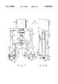
- FIG. 7 is a front view of an embodiment of a pressure test station assembly of the present invention.
- FIG. 8 is a side view of the pressure test station assembly shown in FIG. 7;
- FIG. 9 is a bottom view of the pressure test station assembly shown in FIG. 7;
- FIG. 10 is a side sectional view of the pressure test station shown in FIG. 7, showing the sealed head in contact with an air bag canister.
- FIG. 1 there is shown an embodiment of a system 20 of the present invention, including a loading station 22, proofing station 24, gas fill and weld station 26, and unloading station 28.
- An offline precision link assembly 30 interconnects stations 22, 24, 26 and 28 and carries a plurality of vessels, such as gas bag canisters, from one station to another.
- Loading station 22 removes canisters 32 from transport system 34, such as a conveyor, and places canisters 32 on offline precision link assembly 30.
- Offline precision link assembly 30 moves canisters 32 to each of proofing station 24 and gas fill and weld station 26.
- Unloading station 28 removes canisters 32 from offline precision link assembly 30 and places canisters 32 back onto conveyor 34.
- each of loading station 22 and unloading station 28 is a controllable robot with a pivotable arm.
- Gas fill and weld station 26 is shown in greater detail. In the embodiment shown in the drawings, six such stations are utilized (FIG. 1).
- Gas fill and weld station 26 includes a weld head assembly 36 and a ball shuttle assembly 38.
- FIG. 2 illustrates ball shuttle assembly 38 in an extended position for supplying a weld ball to weld head assembly 36; and
- FIG. 5 illustrates weld head assembly 36 in sealing engagement with a canister 32, such as an air bag canister.
- Ball shuttle assembly 38 (FIG. 2) is movable between a first, extended position (shown in solid lines) for supplying a weld ball to weld head assembly 36; and a second, retracted position (shown in phantom lines) which occurs when weld head assembly 36 is in contact with canister 32.
- Ball shuttle assembly 38 includes a shuttle block 40 which is connected to a rotary actuator 42. More particularly, rotary actuator 42 is connected to and drivingly rotates a first shaft 44, which in turn is connected to a cam 46 via a coupling 48 and second shaft 50.
- Cam 46 includes an extension 52 which drives a rod 54 in an axial direction. Rod 54 is slidably disposed within a bore 56 formed in shuttle block 40.
- Rod 54 includes a collar 58 having a recess (not numbered) therein for receiving extension 52.
- rotary actuator 42 rotates each of first shaft 44, coupling 48, second shaft 50 and cam 46, rod 54 is moved in an axial direction within bore 56.
- Shuttle block 40 receives a weld ball 60 within bore 56 when ball shuttle assembly 38 is moved to the second, retracted position, as shown in phantom lines.
- Weld balls 60 are supplied to bore 56 via a gravity feed tube 62.
- ball shuttle assembly 38 includes a support housing 64 which is slidably attached to a rail 65.
- weld head assembly 36 is shown in greater detail, when in engagement with canister 32.
- Weld head assembly 36 includes a fluid ram assembly 66, which may be either pneumatic or hydraulic and which has an output ram 68.
- a fluid ram assembly 66 Connected to ram 68 of fluid ram assembly 66 is a female housing 70, which in turn engages one end of a compression spring 72.
- Compression spring 72 is connected at the other end thereof to a male housing 74, which in turn is connected to a welding electrode 80.
- LVDT linear variable displacement transducer
- Welding electrode 80 is slidably disposed within a bore 87 which passes through a weld head 78.
- a first seal 82 is operably associated with welding electrode 80, and a second seal 84 is adapted for engagement with and in operable association with canister 32 (FIG. 5).
- Ball retention mechanism 86 Disposed at the bottom end of weld head 78 is a ball retention mechanism 86 which holds a weld ball within weld head 78 during a gas fill operation.
- Ball retention mechanism 86 (FIGS. 2 and 6) includes a projection 88 extending downwardly from weld head 78 and having a notch 90 form therein. Notch 90 receives a rod 92 therein which extends partly across bore 87 to maintain a weld ball 60 thereabove.
- a pair of springs 94 are attached at one end thereof to rod 92 and at another end thereof to weld head 78. Springs 94 thus bias rod 92 to the position shown in FIG. 6, whereby rod 92 extends partially into and across bore 87.
- ball shuttle assembly 38 starts in the position shown in phantom lines in FIG. 2, wherein bore 56 of shuttle block 40 is disposed in coaxial alignment with gravity feed tube 62. A weld ball 60 thus drops into bore 56. Ball shuttle assembly 38 then moves to the position shown in solid lines in FIG. 2, wherein bore 56 is disposed in coaxial alignment with a longitudinal axis of bore 87 of weld head assembly 36.
- Rotary actuator 42 causes rotation of first shaft 44 and movement of rod 54 and weld ball 60 in an axial direction, whereby rod 54 and weld ball 60 are disposed within bore 87 of weld head assembly 36. More particularly, weld ball 60 is moved past ball retention mechanism 86 whereby weld ball 60 is disposed above rod 92.
- Ball retention mechanism 86 maintains weld ball 60 above rod 92 during the procedure of filling canister 32 with gas. Rod 54 is then moved in an axially downward direction by rotation of rotary actuator 42, such that rod 54 is not disposed within bore 87 and ball shuttle assembly 38 is moved to the position shown in phantom lines at a position remote from weld head assembly 36.
- welding electrode 80 When a weld ball 60 is to be supplied to weld head assembly 36, welding electrode 80 is moved to a vertically upward position, whereby welding electrode 80 does not contact weld ball 60 (i.e., welding electrode 80 is spaced above ball retention mechanism 86). After a ball is supplied to weld head assembly 36, ball shuttle assembly 38 (including shuttle block 40) slides out of the way, and canister 32 is moved into engagement with weld head assembly 36, whereby an upper flange 96 of canister 32 is sealingly engaged with second seal 84 of weld head assembly 36.
- welding electrode 80 is moved in a vertically downward direction such that weld ball 60 is stripped from ball retention mechanism 86 and drops into a gas fill opening 98 (FIG. 10) of canister 32.
- Welding electrode 80 continues to move downward and engages weld ball 60 disposed on top of and partly within gas fill opening 98.
- Fluid ram assembly 66 continues to drive output shaft 68, such that a pre-load exists on compression spring 72 (FIG. 5). Concurrently with exertion of the pre-load on compression spring 72, spring loaded piston 100 of LVDT 76 is brought into contact with a fixed surface (not shown). The fixed surface moves in correspondence with welding electrode 80.
- LVDT 76 provides a corresponding output signal to a processor 102 or the like.
- a processor 102 or the like.
- welding electrode 80 will move in a downward direction because of the downward force applied by compression spring 72.
- the fixed surface against which spring loaded piston 100 is disposed moves downward, causing spring loaded piston 100 to in turn move downward.
- a different output signal is supplied by LVDT 76 to processor 100, which indicates that welding has been completed.
- Welding electrode 80 is then moved to a vertically upward position, and canister 32 is moved in a vertically downward direction out of engagement with weld head assembly 36.
- proofing station 24 is shown in greater detail. In the embodiment of the system shown in FIG. 1, six such proofing stations 24 are utilized.
- Proofing station 24 includes a frame 110 attached to a fluid actuated ram assembly 112.
- Ram assembly 12 includes a ram 114 extending into a cylinder 116.
- Cylinder 116 is adapted to hold either a gas or a liquid, i.e., ram assembly 112 can be either pneumatic or hydraulic.
- Ram 114 is pivotably attached at a distal end thereof to links 116 at pins 117, which in turn are pivotably attached to jaws 118 at pins 119.
- Ram 114 includes a slot-shaped opening 123 which allows sliding as well as pivoting movement between ram 114 and link 116.
- link 116 and/or jaw 118 may include an opening which is slot-shaped, thereby allowing sliding as well as pivoting movement between link 116 and jaw 118.
- Jaws 118 are pivotably connected to frame 110 at pins 121, and further connected to fingers 120 such that a slight amount of relative movement may occur therebetween. More particularly, a stub shaft 122 is affixed to jaw 118 and extends through finger 120. A spacer 124 is interposed between jaw 118 and finger 120 and a nut 126 is only slightly tightened against finger 120. A further shaft 128 extends through finger 120 and is affixed to jaw 118. Rather than having a washer between finger 120 and jaw 118, a plurality of Bellville washers 130 are disposed in a stack arrangement and carried by shaft 128. Bellville washers 130 may be slightly compressed, and thus slight relative movement between finger 120 and jaw 118 is possible.
- Frame 110 also includes a head 132 having a pin 134 and a stake 136 extending downwardly therefrom. Pin 134 and stake 136 are adapted to be received within corresponding openings formed in upper flange 96 of canister 32.
- FIG. 10 illustrates head 132 in greater detail.
- a bore 140 is located to be in substantially coaxial alignment with gas fill opening 98 of canister 32 when head 132 is engaging canister 32.
- Bore 140 is disposed in fluid communication with a further passageway 142 which receives a source of pressurized fluid from an external source (not shown).
- bore 140 is formed within a cylindrical member 144.
- Cylindrical member 144 is slidably disposed within a corresponding opening 146 of head 132.
- Seals 148, 150 allow fluid communication between passageway 142 and bore 140, while preventing escape of gas to the outside ambient environment.
- a third seal 152 is carried on an end face of cylindrical member 144 and surrounds gas fill opening 98 when head 132 engages canister 32.
- a compression spring 154 is disposed at an end of cylindrical member 144 which is opposite from third seal 152 and between a fixed member 156 and a shoulder 158.
- a slot 160 formed in cylindrical member 144 and a nut 162 allow adjustment of the preload on spring 154.
- ram 114 is moved to a downward, extended position which in turn rotates jaws 118 and fingers 120 to the open position.
- a canister 32 is brought into contact with head 132 and aligned with pin 134 and stake 136.
- either canister 32 may be rotated or frame 110 may be rotated.
- ram 114 is retracted which causes rotation of jaws 118 and moves fingers 120 underneath of upper flange 96 of canister 32. Because of manufacturing defects and/or weld spatter which may exist as a result of earlier welding to canister 32, upper flange 96 may not be oriented correctly relative to head 132.
- upper flange 96 may not be parallel with and end face of head 132, which in turn results in inadequate sealing therebetween utilizing third seal 152.
- a high pressure gas is introduced to the interior of canister 32 and maintained therein for a predetermined amount of time. If a proper sealing does not exist between canister 32 and head 132, the pressure testing will indicate that a leakage path exists within canister 32, when in fact no such leakage path may be present.
- the present invention ensures that upper flange 96 is correctly oriented relative to head 132 to prevent such a problem. To wit, as ram 114 is retracted, finger 120 may engage weld spatter 164 as indicated in FIG. 7.
- the slot formed in link 116 and/or jaw 118, as well as bellville washer 130 allow one jaw 118 and finger 120 to be disposed at a different angle with respect to shaft 114 then the other jaw 118 and finger 120.
- the present invention therefore allows upper flange 96 to be drawn flat against end face 166 of head 132 to ensure proper sealing engagement therebetween.
Abstract
Description
Claims (20)
Priority Applications (1)
| Application Number | Priority Date | Filing Date | Title |
|---|---|---|---|
| US08/336,764 US5495699A (en) | 1994-11-09 | 1994-11-09 | Method and apparatus for pressure filling and sealing a vessel |
Applications Claiming Priority (1)
| Application Number | Priority Date | Filing Date | Title |
|---|---|---|---|
| US08/336,764 US5495699A (en) | 1994-11-09 | 1994-11-09 | Method and apparatus for pressure filling and sealing a vessel |
Publications (1)
| Publication Number | Publication Date |
|---|---|
| US5495699A true US5495699A (en) | 1996-03-05 |
Family
ID=23317550
Family Applications (1)
| Application Number | Title | Priority Date | Filing Date |
|---|---|---|---|
| US08/336,764 Expired - Fee Related US5495699A (en) | 1994-11-09 | 1994-11-09 | Method and apparatus for pressure filling and sealing a vessel |
Country Status (1)
| Country | Link |
|---|---|
| US (1) | US5495699A (en) |
Cited By (7)
| Publication number | Priority date | Publication date | Assignee | Title |
|---|---|---|---|---|
| NL1003331C2 (en) * | 1995-06-14 | 1998-04-10 | Morton Int Inc | Method for combined filling with gas and testing pressure vessels for tightness. |
| US5787685A (en) * | 1996-09-19 | 1998-08-04 | Autoliv Asp, Inc. | Process and apparatus for filling liquid fuel storage containers and assembling such containers into fluid fueled airbag inflators |
| US5791122A (en) * | 1996-06-17 | 1998-08-11 | Rwc, Inc. | System and method for charging canisters with a high pressure gas |
| US20030138980A1 (en) * | 1996-01-02 | 2003-07-24 | Moden Walter L. | Method of temporarily securing a die to a burn-in carrier |
| US20060241470A1 (en) * | 2005-03-23 | 2006-10-26 | Misonix Incorporated | Ultrasonic wound debrider probe and method of use |
| US20080058775A1 (en) * | 2006-08-29 | 2008-03-06 | Darian Alexander L | Ultrasonic debrider probe and method of use |
| US20160145086A1 (en) * | 2014-11-25 | 2016-05-26 | The Wine Group, Inc. | Cap gripper |
Citations (10)
| Publication number | Priority date | Publication date | Assignee | Title |
|---|---|---|---|---|
| US619681A (en) * | 1899-02-14 | Can-soldering machine | ||
| US3057131A (en) * | 1960-08-24 | 1962-10-09 | Robert E Mckinley | Hydraulic ball press with automatic ball feed |
| US3212228A (en) * | 1962-06-11 | 1965-10-19 | Crosman Arms Company Inc | Machine for filling and capping cartridges |
| US3247640A (en) * | 1960-06-06 | 1966-04-26 | Colgate Palmolive Co | Filling aerosol containers |
| US3577696A (en) * | 1969-04-29 | 1971-05-04 | Chandler Evans Inc | Method of filling a pressure vessel assembly |
| US3983678A (en) * | 1974-12-05 | 1976-10-05 | Greer Hydraulics, Inc. | Method and apparatus for charging a hydro-pneumatic reservoir with gas under pressure |
| US4255916A (en) * | 1978-10-23 | 1981-03-17 | The United States Of America As Represented By The Secretary Of The Navy | Method of charging and hermetically sealing high pressure gas container |
| US4439976A (en) * | 1979-05-21 | 1984-04-03 | Tokico Ltd. | Method for filling gas into a metal container |
| US4458734A (en) * | 1982-01-29 | 1984-07-10 | Scholle Corporation | Apparatus and method for aseptically filling a container |
| US4712353A (en) * | 1982-06-01 | 1987-12-15 | Monroe Auto Equipment Company | Gas pressurized shock absorber assembly |
-
1994
- 1994-11-09 US US08/336,764 patent/US5495699A/en not_active Expired - Fee Related
Patent Citations (10)
| Publication number | Priority date | Publication date | Assignee | Title |
|---|---|---|---|---|
| US619681A (en) * | 1899-02-14 | Can-soldering machine | ||
| US3247640A (en) * | 1960-06-06 | 1966-04-26 | Colgate Palmolive Co | Filling aerosol containers |
| US3057131A (en) * | 1960-08-24 | 1962-10-09 | Robert E Mckinley | Hydraulic ball press with automatic ball feed |
| US3212228A (en) * | 1962-06-11 | 1965-10-19 | Crosman Arms Company Inc | Machine for filling and capping cartridges |
| US3577696A (en) * | 1969-04-29 | 1971-05-04 | Chandler Evans Inc | Method of filling a pressure vessel assembly |
| US3983678A (en) * | 1974-12-05 | 1976-10-05 | Greer Hydraulics, Inc. | Method and apparatus for charging a hydro-pneumatic reservoir with gas under pressure |
| US4255916A (en) * | 1978-10-23 | 1981-03-17 | The United States Of America As Represented By The Secretary Of The Navy | Method of charging and hermetically sealing high pressure gas container |
| US4439976A (en) * | 1979-05-21 | 1984-04-03 | Tokico Ltd. | Method for filling gas into a metal container |
| US4458734A (en) * | 1982-01-29 | 1984-07-10 | Scholle Corporation | Apparatus and method for aseptically filling a container |
| US4712353A (en) * | 1982-06-01 | 1987-12-15 | Monroe Auto Equipment Company | Gas pressurized shock absorber assembly |
Cited By (12)
| Publication number | Priority date | Publication date | Assignee | Title |
|---|---|---|---|---|
| NL1003331C2 (en) * | 1995-06-14 | 1998-04-10 | Morton Int Inc | Method for combined filling with gas and testing pressure vessels for tightness. |
| US20030138980A1 (en) * | 1996-01-02 | 2003-07-24 | Moden Walter L. | Method of temporarily securing a die to a burn-in carrier |
| US20030206034A1 (en) * | 1996-01-02 | 2003-11-06 | Moden Walter L. | Method of temporarily securing a die to a burn-in carrier |
| US6894521B2 (en) | 1996-01-02 | 2005-05-17 | Micron Technology, Inc. | Burn-in carrier for a semiconductor die |
| US20050272172A1 (en) * | 1996-01-02 | 2005-12-08 | Moden Walter L | Method of temporarily securing a die to a burn-in carrier |
| US7105380B2 (en) * | 1996-01-02 | 2006-09-12 | Micron Technology, Inc. | Method of temporarily securing a die to a burn-in carrier |
| US5791122A (en) * | 1996-06-17 | 1998-08-11 | Rwc, Inc. | System and method for charging canisters with a high pressure gas |
| US5787685A (en) * | 1996-09-19 | 1998-08-04 | Autoliv Asp, Inc. | Process and apparatus for filling liquid fuel storage containers and assembling such containers into fluid fueled airbag inflators |
| US20060241470A1 (en) * | 2005-03-23 | 2006-10-26 | Misonix Incorporated | Ultrasonic wound debrider probe and method of use |
| US20080058775A1 (en) * | 2006-08-29 | 2008-03-06 | Darian Alexander L | Ultrasonic debrider probe and method of use |
| US20160145086A1 (en) * | 2014-11-25 | 2016-05-26 | The Wine Group, Inc. | Cap gripper |
| US10017368B2 (en) * | 2014-11-25 | 2018-07-10 | The Wine Group, Inc. | Cap gripper |
Similar Documents
| Publication | Publication Date | Title |
|---|---|---|
| US5495699A (en) | Method and apparatus for pressure filling and sealing a vessel | |
| US4266905A (en) | Apparatus for acquiring workpieces from a storage bin or the like | |
| CN110340033B (en) | Assembly line type air tightness detection device | |
| JP2009509748A (en) | Viscous material dispensing system with parameter monitoring and method of operating such a system | |
| CZ283120B6 (en) | Apparatus for saturation of liquids with gases | |
| CA2112418C (en) | Automatic riveting machine | |
| KR100283852B1 (en) | Probe device | |
| US4025371A (en) | Welding containers | |
| JP2575370B2 (en) | Inspection method and inspection equipment for container characteristics, especially for bottle-shaped containers | |
| US2462642A (en) | Apparatus for filling containers of pressure fluids | |
| CA2092214C (en) | Procedure and apparatus for feeding a material into a pressurized space | |
| JPS6356516B2 (en) | ||
| EP1036755A1 (en) | Fitting clamping device for pressure vessel | |
| US20060104784A1 (en) | Apparatus for picking up a defective portion replica | |
| JPS6138831A (en) | Assembly device of parts | |
| EP3746285B1 (en) | Apparatus for cap applicator and method of operating the apparatus | |
| US4308900A (en) | Container filling system | |
| US20020118008A1 (en) | Autohandler | |
| US5791122A (en) | System and method for charging canisters with a high pressure gas | |
| JPH07267297A (en) | Filling valve | |
| US5829223A (en) | Apparatus for charging canisters with a high pressure gas | |
| CN110328153A (en) | Blowout control tool pressure testing device in a kind of oil drilling multistation | |
| JP3202685B2 (en) | Head unit for pressure vessel inspection and pressure vessel inspection device | |
| KR100235803B1 (en) | Automatic balance charging pipe device | |
| JPH0347975B2 (en) |
Legal Events
| Date | Code | Title | Description |
|---|---|---|---|
| AS | Assignment |
Owner name: WELDUN INTERNATIONAL, INC., MICHIGAN Free format text: ASSIGNMENT OF ASSIGNORS INTEREST;ASSIGNOR:BUCKLEY, THOMAS I., JR.;REEL/FRAME:007228/0137 Effective date: 19941103 |
|
| FEPP | Fee payment procedure |
Free format text: PAYOR NUMBER ASSIGNED (ORIGINAL EVENT CODE: ASPN); ENTITY STATUS OF PATENT OWNER: LARGE ENTITY |
|
| AS | Assignment |
Owner name: HUNTINGTON NATIONAL BANK, THE, OHIO Free format text: SECURITY INTEREST;ASSIGNOR:WELDUN INTERNATIONAL, LTD., D/B/A WELDUN INTERNATIONAL, LLC;REEL/FRAME:009614/0114 Effective date: 19981109 |
|
| AS | Assignment |
Owner name: WELDUN INTERNATIONAL, LTD., MICHIGAN Free format text: ASSIGNMENT OF ASSIGNORS INTEREST;ASSIGNOR:ROBERT BOSCH CORPORATION, SUCCESSOR BYMERGER TO WELDUN INERNATIONAL, INC.;REEL/FRAME:009624/0476 Effective date: 19981110 |
|
| AS | Assignment |
Owner name: WELDUN INTERNATIONAL, LTD., MICHIGAN Free format text: ASSIGNMENT OF ASSIGNORS INTEREST;ASSIGNOR:ROBERT BOSCH CORPORATION;REEL/FRAME:009756/0361 Effective date: 19981110 |
|
| FPAY | Fee payment |
Year of fee payment: 4 |
|
| REMI | Maintenance fee reminder mailed | ||
| LAPS | Lapse for failure to pay maintenance fees | ||
| FP | Lapsed due to failure to pay maintenance fee |
Effective date: 20040305 |
|
| STCH | Information on status: patent discontinuation |
Free format text: PATENT EXPIRED DUE TO NONPAYMENT OF MAINTENANCE FEES UNDER 37 CFR 1.362 |