US5493845A - Method for forming, filling and sealing a sterile flexible container - Google Patents
Method for forming, filling and sealing a sterile flexible container Download PDFInfo
- Publication number
- US5493845A US5493845A US08/283,017 US28301794A US5493845A US 5493845 A US5493845 A US 5493845A US 28301794 A US28301794 A US 28301794A US 5493845 A US5493845 A US 5493845A
- Authority
- US
- United States
- Prior art keywords
- film strip
- solution
- layer
- flexible
- sealing
- Prior art date
- Legal status (The legal status is an assumption and is not a legal conclusion. Google has not performed a legal analysis and makes no representation as to the accuracy of the status listed.)
- Expired - Lifetime
Links
Images


Classifications
-
- A—HUMAN NECESSITIES
- A61—MEDICAL OR VETERINARY SCIENCE; HYGIENE
- A61J—CONTAINERS SPECIALLY ADAPTED FOR MEDICAL OR PHARMACEUTICAL PURPOSES; DEVICES OR METHODS SPECIALLY ADAPTED FOR BRINGING PHARMACEUTICAL PRODUCTS INTO PARTICULAR PHYSICAL OR ADMINISTERING FORMS; DEVICES FOR ADMINISTERING FOOD OR MEDICINES ORALLY; BABY COMFORTERS; DEVICES FOR RECEIVING SPITTLE
- A61J1/00—Containers specially adapted for medical or pharmaceutical purposes
- A61J1/14—Details; Accessories therefor
- A61J1/1406—Septums, pierceable membranes
-
- A—HUMAN NECESSITIES
- A61—MEDICAL OR VETERINARY SCIENCE; HYGIENE
- A61J—CONTAINERS SPECIALLY ADAPTED FOR MEDICAL OR PHARMACEUTICAL PURPOSES; DEVICES OR METHODS SPECIALLY ADAPTED FOR BRINGING PHARMACEUTICAL PRODUCTS INTO PARTICULAR PHYSICAL OR ADMINISTERING FORMS; DEVICES FOR ADMINISTERING FOOD OR MEDICINES ORALLY; BABY COMFORTERS; DEVICES FOR RECEIVING SPITTLE
- A61J1/00—Containers specially adapted for medical or pharmaceutical purposes
- A61J1/05—Containers specially adapted for medical or pharmaceutical purposes for collecting, storing or administering blood, plasma or medical fluids ; Infusion or perfusion containers
- A61J1/10—Bag-type containers
-
- A—HUMAN NECESSITIES
- A61—MEDICAL OR VETERINARY SCIENCE; HYGIENE
- A61M—DEVICES FOR INTRODUCING MEDIA INTO, OR ONTO, THE BODY; DEVICES FOR TRANSDUCING BODY MEDIA OR FOR TAKING MEDIA FROM THE BODY; DEVICES FOR PRODUCING OR ENDING SLEEP OR STUPOR
- A61M39/00—Tubes, tube connectors, tube couplings, valves, access sites or the like, specially adapted for medical use
- A61M39/22—Valves or arrangement of valves
- A61M39/221—Frangible or pierceable closures within tubing
-
- B—PERFORMING OPERATIONS; TRANSPORTING
- B29—WORKING OF PLASTICS; WORKING OF SUBSTANCES IN A PLASTIC STATE IN GENERAL
- B29C—SHAPING OR JOINING OF PLASTICS; SHAPING OF MATERIAL IN A PLASTIC STATE, NOT OTHERWISE PROVIDED FOR; AFTER-TREATMENT OF THE SHAPED PRODUCTS, e.g. REPAIRING
- B29C65/00—Joining or sealing of preformed parts, e.g. welding of plastics materials; Apparatus therefor
- B29C65/02—Joining or sealing of preformed parts, e.g. welding of plastics materials; Apparatus therefor by heating, with or without pressure
-
- B—PERFORMING OPERATIONS; TRANSPORTING
- B29—WORKING OF PLASTICS; WORKING OF SUBSTANCES IN A PLASTIC STATE IN GENERAL
- B29C—SHAPING OR JOINING OF PLASTICS; SHAPING OF MATERIAL IN A PLASTIC STATE, NOT OTHERWISE PROVIDED FOR; AFTER-TREATMENT OF THE SHAPED PRODUCTS, e.g. REPAIRING
- B29C66/00—General aspects of processes or apparatus for joining preformed parts
- B29C66/001—Joining in special atmospheres
- B29C66/0012—Joining in special atmospheres characterised by the type of environment
- B29C66/0018—Joining in special atmospheres characterised by the type of environment being sterile
-
- B—PERFORMING OPERATIONS; TRANSPORTING
- B29—WORKING OF PLASTICS; WORKING OF SUBSTANCES IN A PLASTIC STATE IN GENERAL
- B29C—SHAPING OR JOINING OF PLASTICS; SHAPING OF MATERIAL IN A PLASTIC STATE, NOT OTHERWISE PROVIDED FOR; AFTER-TREATMENT OF THE SHAPED PRODUCTS, e.g. REPAIRING
- B29C66/00—General aspects of processes or apparatus for joining preformed parts
- B29C66/01—General aspects dealing with the joint area or with the area to be joined
- B29C66/05—Particular design of joint configurations
- B29C66/10—Particular design of joint configurations particular design of the joint cross-sections
- B29C66/11—Joint cross-sections comprising a single joint-segment, i.e. one of the parts to be joined comprising a single joint-segment in the joint cross-section
- B29C66/112—Single lapped joints
-
- B—PERFORMING OPERATIONS; TRANSPORTING
- B29—WORKING OF PLASTICS; WORKING OF SUBSTANCES IN A PLASTIC STATE IN GENERAL
- B29C—SHAPING OR JOINING OF PLASTICS; SHAPING OF MATERIAL IN A PLASTIC STATE, NOT OTHERWISE PROVIDED FOR; AFTER-TREATMENT OF THE SHAPED PRODUCTS, e.g. REPAIRING
- B29C66/00—General aspects of processes or apparatus for joining preformed parts
- B29C66/01—General aspects dealing with the joint area or with the area to be joined
- B29C66/05—Particular design of joint configurations
- B29C66/10—Particular design of joint configurations particular design of the joint cross-sections
- B29C66/13—Single flanged joints; Fin-type joints; Single hem joints; Edge joints; Interpenetrating fingered joints; Other specific particular designs of joint cross-sections not provided for in groups B29C66/11 - B29C66/12
- B29C66/131—Single flanged joints, i.e. one of the parts to be joined being rigid and flanged in the joint area
-
- B—PERFORMING OPERATIONS; TRANSPORTING
- B29—WORKING OF PLASTICS; WORKING OF SUBSTANCES IN A PLASTIC STATE IN GENERAL
- B29C—SHAPING OR JOINING OF PLASTICS; SHAPING OF MATERIAL IN A PLASTIC STATE, NOT OTHERWISE PROVIDED FOR; AFTER-TREATMENT OF THE SHAPED PRODUCTS, e.g. REPAIRING
- B29C66/00—General aspects of processes or apparatus for joining preformed parts
- B29C66/01—General aspects dealing with the joint area or with the area to be joined
- B29C66/05—Particular design of joint configurations
- B29C66/20—Particular design of joint configurations particular design of the joint lines, e.g. of the weld lines
- B29C66/24—Particular design of joint configurations particular design of the joint lines, e.g. of the weld lines said joint lines being closed or non-straight
- B29C66/242—Particular design of joint configurations particular design of the joint lines, e.g. of the weld lines said joint lines being closed or non-straight said joint lines being closed, i.e. forming closed contours
- B29C66/2422—Particular design of joint configurations particular design of the joint lines, e.g. of the weld lines said joint lines being closed or non-straight said joint lines being closed, i.e. forming closed contours being circular, oval or elliptical
- B29C66/24225—Particular design of joint configurations particular design of the joint lines, e.g. of the weld lines said joint lines being closed or non-straight said joint lines being closed, i.e. forming closed contours being circular, oval or elliptical being elliptical
-
- B—PERFORMING OPERATIONS; TRANSPORTING
- B29—WORKING OF PLASTICS; WORKING OF SUBSTANCES IN A PLASTIC STATE IN GENERAL
- B29C—SHAPING OR JOINING OF PLASTICS; SHAPING OF MATERIAL IN A PLASTIC STATE, NOT OTHERWISE PROVIDED FOR; AFTER-TREATMENT OF THE SHAPED PRODUCTS, e.g. REPAIRING
- B29C66/00—General aspects of processes or apparatus for joining preformed parts
- B29C66/01—General aspects dealing with the joint area or with the area to be joined
- B29C66/05—Particular design of joint configurations
- B29C66/306—Applying a mark during joining
-
- B—PERFORMING OPERATIONS; TRANSPORTING
- B29—WORKING OF PLASTICS; WORKING OF SUBSTANCES IN A PLASTIC STATE IN GENERAL
- B29C—SHAPING OR JOINING OF PLASTICS; SHAPING OF MATERIAL IN A PLASTIC STATE, NOT OTHERWISE PROVIDED FOR; AFTER-TREATMENT OF THE SHAPED PRODUCTS, e.g. REPAIRING
- B29C66/00—General aspects of processes or apparatus for joining preformed parts
- B29C66/50—General aspects of joining tubular articles; General aspects of joining long products, i.e. bars or profiled elements; General aspects of joining single elements to tubular articles, hollow articles or bars; General aspects of joining several hollow-preforms to form hollow or tubular articles
- B29C66/51—Joining tubular articles, profiled elements or bars; Joining single elements to tubular articles, hollow articles or bars; Joining several hollow-preforms to form hollow or tubular articles
- B29C66/53—Joining single elements to tubular articles, hollow articles or bars
- B29C66/532—Joining single elements to the wall of tubular articles, hollow articles or bars
- B29C66/5324—Joining single elements to the wall of tubular articles, hollow articles or bars said single elements being substantially annular, i.e. of finite length
- B29C66/53245—Joining single elements to the wall of tubular articles, hollow articles or bars said single elements being substantially annular, i.e. of finite length said articles being hollow
- B29C66/53246—Joining single elements to the wall of tubular articles, hollow articles or bars said single elements being substantially annular, i.e. of finite length said articles being hollow said single elements being spouts, e.g. joining spouts to containers
- B29C66/53247—Joining single elements to the wall of tubular articles, hollow articles or bars said single elements being substantially annular, i.e. of finite length said articles being hollow said single elements being spouts, e.g. joining spouts to containers said spouts comprising flanges
-
- B—PERFORMING OPERATIONS; TRANSPORTING
- B29—WORKING OF PLASTICS; WORKING OF SUBSTANCES IN A PLASTIC STATE IN GENERAL
- B29C—SHAPING OR JOINING OF PLASTICS; SHAPING OF MATERIAL IN A PLASTIC STATE, NOT OTHERWISE PROVIDED FOR; AFTER-TREATMENT OF THE SHAPED PRODUCTS, e.g. REPAIRING
- B29C66/00—General aspects of processes or apparatus for joining preformed parts
- B29C66/70—General aspects of processes or apparatus for joining preformed parts characterised by the composition, physical properties or the structure of the material of the parts to be joined; Joining with non-plastics material
- B29C66/72—General aspects of processes or apparatus for joining preformed parts characterised by the composition, physical properties or the structure of the material of the parts to be joined; Joining with non-plastics material characterised by the structure of the material of the parts to be joined
- B29C66/723—General aspects of processes or apparatus for joining preformed parts characterised by the composition, physical properties or the structure of the material of the parts to be joined; Joining with non-plastics material characterised by the structure of the material of the parts to be joined being multi-layered
- B29C66/7234—General aspects of processes or apparatus for joining preformed parts characterised by the composition, physical properties or the structure of the material of the parts to be joined; Joining with non-plastics material characterised by the structure of the material of the parts to be joined being multi-layered comprising a barrier layer
- B29C66/72341—General aspects of processes or apparatus for joining preformed parts characterised by the composition, physical properties or the structure of the material of the parts to be joined; Joining with non-plastics material characterised by the structure of the material of the parts to be joined being multi-layered comprising a barrier layer for gases
-
- A—HUMAN NECESSITIES
- A61—MEDICAL OR VETERINARY SCIENCE; HYGIENE
- A61B—DIAGNOSIS; SURGERY; IDENTIFICATION
- A61B50/00—Containers, covers, furniture or holders specially adapted for surgical or diagnostic appliances or instruments, e.g. sterile covers
- A61B50/30—Containers specially adapted for packaging, protecting, dispensing, collecting or disposing of surgical or diagnostic appliances or instruments
- A61B2050/314—Flexible bags or pouches
-
- A—HUMAN NECESSITIES
- A61—MEDICAL OR VETERINARY SCIENCE; HYGIENE
- A61M—DEVICES FOR INTRODUCING MEDIA INTO, OR ONTO, THE BODY; DEVICES FOR TRANSDUCING BODY MEDIA OR FOR TAKING MEDIA FROM THE BODY; DEVICES FOR PRODUCING OR ENDING SLEEP OR STUPOR
- A61M2207/00—Methods of manufacture, assembly or production
-
- B—PERFORMING OPERATIONS; TRANSPORTING
- B29—WORKING OF PLASTICS; WORKING OF SUBSTANCES IN A PLASTIC STATE IN GENERAL
- B29C—SHAPING OR JOINING OF PLASTICS; SHAPING OF MATERIAL IN A PLASTIC STATE, NOT OTHERWISE PROVIDED FOR; AFTER-TREATMENT OF THE SHAPED PRODUCTS, e.g. REPAIRING
- B29C59/00—Surface shaping of articles, e.g. embossing; Apparatus therefor
- B29C59/007—Forming single grooves or ribs, e.g. tear lines, weak spots
-
- B—PERFORMING OPERATIONS; TRANSPORTING
- B29—WORKING OF PLASTICS; WORKING OF SUBSTANCES IN A PLASTIC STATE IN GENERAL
- B29C—SHAPING OR JOINING OF PLASTICS; SHAPING OF MATERIAL IN A PLASTIC STATE, NOT OTHERWISE PROVIDED FOR; AFTER-TREATMENT OF THE SHAPED PRODUCTS, e.g. REPAIRING
- B29C65/00—Joining or sealing of preformed parts, e.g. welding of plastics materials; Apparatus therefor
- B29C65/02—Joining or sealing of preformed parts, e.g. welding of plastics materials; Apparatus therefor by heating, with or without pressure
- B29C65/08—Joining or sealing of preformed parts, e.g. welding of plastics materials; Apparatus therefor by heating, with or without pressure using ultrasonic vibrations
-
- B—PERFORMING OPERATIONS; TRANSPORTING
- B29—WORKING OF PLASTICS; WORKING OF SUBSTANCES IN A PLASTIC STATE IN GENERAL
- B29C—SHAPING OR JOINING OF PLASTICS; SHAPING OF MATERIAL IN A PLASTIC STATE, NOT OTHERWISE PROVIDED FOR; AFTER-TREATMENT OF THE SHAPED PRODUCTS, e.g. REPAIRING
- B29C65/00—Joining or sealing of preformed parts, e.g. welding of plastics materials; Apparatus therefor
- B29C65/02—Joining or sealing of preformed parts, e.g. welding of plastics materials; Apparatus therefor by heating, with or without pressure
- B29C65/18—Joining or sealing of preformed parts, e.g. welding of plastics materials; Apparatus therefor by heating, with or without pressure using heated tools
-
- B—PERFORMING OPERATIONS; TRANSPORTING
- B29—WORKING OF PLASTICS; WORKING OF SUBSTANCES IN A PLASTIC STATE IN GENERAL
- B29C—SHAPING OR JOINING OF PLASTICS; SHAPING OF MATERIAL IN A PLASTIC STATE, NOT OTHERWISE PROVIDED FOR; AFTER-TREATMENT OF THE SHAPED PRODUCTS, e.g. REPAIRING
- B29C65/00—Joining or sealing of preformed parts, e.g. welding of plastics materials; Apparatus therefor
- B29C65/48—Joining or sealing of preformed parts, e.g. welding of plastics materials; Apparatus therefor using adhesives, i.e. using supplementary joining material; solvent bonding
-
- B—PERFORMING OPERATIONS; TRANSPORTING
- B29—WORKING OF PLASTICS; WORKING OF SUBSTANCES IN A PLASTIC STATE IN GENERAL
- B29L—INDEXING SCHEME ASSOCIATED WITH SUBCLASS B29C, RELATING TO PARTICULAR ARTICLES
- B29L2031/00—Other particular articles
- B29L2031/712—Containers; Packaging elements or accessories, Packages
- B29L2031/7148—Blood bags, medical bags
-
- Y—GENERAL TAGGING OF NEW TECHNOLOGICAL DEVELOPMENTS; GENERAL TAGGING OF CROSS-SECTIONAL TECHNOLOGIES SPANNING OVER SEVERAL SECTIONS OF THE IPC; TECHNICAL SUBJECTS COVERED BY FORMER USPC CROSS-REFERENCE ART COLLECTIONS [XRACs] AND DIGESTS
- Y10—TECHNICAL SUBJECTS COVERED BY FORMER USPC
- Y10S—TECHNICAL SUBJECTS COVERED BY FORMER USPC CROSS-REFERENCE ART COLLECTIONS [XRACs] AND DIGESTS
- Y10S383/00—Flexible bags
- Y10S383/906—Dispensing feature
-
- Y—GENERAL TAGGING OF NEW TECHNOLOGICAL DEVELOPMENTS; GENERAL TAGGING OF CROSS-SECTIONAL TECHNOLOGIES SPANNING OVER SEVERAL SECTIONS OF THE IPC; TECHNICAL SUBJECTS COVERED BY FORMER USPC CROSS-REFERENCE ART COLLECTIONS [XRACs] AND DIGESTS
- Y10—TECHNICAL SUBJECTS COVERED BY FORMER USPC
- Y10S—TECHNICAL SUBJECTS COVERED BY FORMER USPC CROSS-REFERENCE ART COLLECTIONS [XRACs] AND DIGESTS
- Y10S604/00—Surgery
- Y10S604/905—Aseptic connectors or couplings, e.g. frangible, piercable
Definitions
- the present invention relates to a sterile formed, filled and sealed flexible solution container with an attached administration port system and, in particular, to a sterile formed, filled and sealed flexible solution container and an attached sterile administration port assembly which allows for the sterile maintenance and delivery of a sterile medical solution.
- a "boat" administration port may be sealed by many known thermal bonding processes between the opposed inner layers of two flexible film sheets so as to form a flexible solution container. Ultrasonic welding or solvent bonding may also be used to seal the boat port between the film layers.
- the majority of flexible films used for flexible solution containers are monolayer PVC films. Recently, a few multiple-layer, extrusion or adhesive laminated films have been used in form, fill and seal packaging for producing flexible solution containers.
- the inner, solution contacting layer must be substantially inert to the solution. Also the inner layer of the film must be readily bondable to itself. Furthermore, the inner film layer must be compatible with any material used for attachable components, such as administration ports.
- the outer layer of the laminated film must be durable and also compatible with other materials that may contact or be attached to the outside surface. If neither the inner or outer layer has the desired solution maintaining and barrier characteristics, such as low moisture and/or oxygen permeability, additional film layers may be required between the inner and outer layers.
- a primary disadvantage of known flexible solution containers assembled according to the above described boat port construction is that the port material typically has a higher oxygen permeability than the film material.
- the permeability characteristic of the port material is much greater than the similar characteristic for the laminated film used to make the flexible container.
- the administration port of known flexible solution containers is often the weakest part of the barrier characteristics. This factor becomes extremely important for certain medical solutions which are sensitive to oxygen or other penetrating gases, for example.
- any of the above deficiencies has been overcome by overwrapping the flexible solution container and/or the administration ports, with an overwrap material. While this redundancy in packaging may provide the desired barrier characteristics, the overwrap material introduces two important disadvantages. First, there is the additional cost to fabricate and later dispose of the overwrap. Second, there is concern that extractables from the overwrap material may migrate into the contained solution during post filling procedures, such as during the sterilization process or even during shelf life.
- Pre-formed rigid administration ports constitute potential places of leakage and are potential points of entry in an otherwise sealed, durable, flexible container. Moreover, the rigid ports make it more difficult to arrange an outer protective package around the flexible container. Also the protective overwrap only initially prevents the packaged solution from losing its potency due to evaporation or diffusion. When the overwrap is removed or breached, the administration ports positioned between two layers of film is an effective breach in the barrier characteristics of the flexible container for certain sensitive drugs.
- the film can be controlled easily by the choice of the film components and structure.
- the oxygen permeation properties of the port system are not as easily controlled.
- this consistency is not achieved in known flexible containers having pre-formed rigid port systems sealed between the film layers of the flexible container.
- the known flexible container and administration port systems often include an entry port in addition to the administration port.
- the entry ports are likewise inserted between film layers at the perimeter seal. Both ports are thus a breach through an otherwise effective perimeter barrier.
- a pierceable diaphragm is provided in the administration port to prevent an outflow of solution.
- the flexible container may be filled through the entry port. After filling, the entry port is sealed, but the ports, and specifically the exposed port material, is the potential point of entry for compromising the barrier characteristics.
- Flange ports are an alternative to boat ports and may be advantageously sealed to a film surface.
- the flexible solution container produced by the known form, fill and seal process the use of flange ports does not remove the barrier deficiency.
- a flexible parenteral solution container including a flange-sealed port assembly is disclosed in U.S. Pat. No. 4,695,337 to Christine and in U.S. Pat. No. 4779397 to Christine et al.
- a major disadvantage of the disclosed flexible solution container is that the flexible film barrier of the flexible container is purposefully breached during the assembly steps to mount and seal the administration port or fitment to the inside surface of the flexible container, as seen for example in FIGS. 4a-4d of the patents.
- parenteral solutions may be subjected to degradation during the shelf life of the product solution.
- an overwrap may provide some protection for the flexible container and the port administration system from contamination or degradation during shelf life, the overwrap introduces additional concerns that are increasingly desirable to avoid.
- a flexible container that includes an attached administration port system that is accessible by a variety of piercing pins, including center point pins, beveled pins and blunt pins as well as a port system that is compatible with the various lengths and other dimensions of the most common piercing pins.
- the present invention relates to a sterilely formed, sterilely filled, and sterilely sealed flexible solution container including a sheet of laminated flexible film folded over along a saddle line so that a portion of the inner surface of the sheet faces a second portion of the inner surface of the sheet.
- a continuous peripheral line of sealing contact along the perimeter of the facing portions of this sheet is provided so as to form an inner sealed chamber between the first and second facing portions of the film
- a rigid administration port including a tubular member having a first and second open end is provided for attachment to the outer surface of the flexible container.
- An integral circumferential flange surrounds the first open end of the tubular port and the flange is circumferentially sealed generally along the axis of a sump portion outwardly formed in the bottom surface of the flexible film of the formed, filled and sealed chamber. The integrity of the sealed chamber is not compromised by the attached tubular port.
- An access fitment is provided on the second open end of the tubular port and a removable cover for closing the second open end is provided.
- a penetrator element is slidably contained within the tubular port and has a contained sharp end for slidably protruding beyond the circumferential flange at the first open end of the tubular port member so as to pierce the film surface and penetrate the sealed chamber. At least one fluid passageway through the penetrator element from the pierced sealed chamber to the access fitment is provided.
- the present invention relates to an administration port for use with a formed, filled and sealed, flexible solution container.
- the port includes a rigid, tubular body having a first and second open end.
- a circumferential flange surrounds the first open end of the tubular body and is circumferentially sealable to the outer surface of the flexible container.
- An access fitment is provided at the second open end of the tubular body.
- a resilient or elastomeric cover is removably attached to the access fitment to initially close the second open end of the tubular body and maintain the sterile condition of the port system until used.
- a piercing mechanism or penetrator is provided in the administration administration port to initiate fluid flow communication from the sealed flexible container to the access fitment.
- the penetrator element includes a slidably cylindrical member initially wholly contained within the tubular body.
- the penetrator has a sharp end for slidably protruding beyond the circumferential flange so as to pierce the film forming the sealed inner chamber.
- the penetrator includes a hollow portion opening into the sharp beveled edge at the front end.
- a passageway is provided through the penetrator element from the pierced surface of the sealed container to the access fitment for sterile fluid flow of the solution from the flexible container.
- the present invention is also directed to a sterile method for forming, filling and sealing a continuous, longitudinal strip of flexible laminated film into a plurality of individual flexible containers.
- the continuous film strip enters the sterile core and is sterilized and dried by any suitable sterilizing process.
- the flat, continuous film strip is continuously indexed through the sterile core.
- a plurality of center portions are outwardly stretched to form a plurality of discrete fluid sumps.
- the continuous film strip is then formed into a continuous U-shaped trough having a rounded bottom surface and two inside facing surfaces. Transverse portions of the sides surfaces are sealed together and with the bottom surface forms an open pocket.
- the pocket is filled with a separately separately sterilized solution and the top surface is sealed to form sealed chambers.
- the continuous strip is cut coincident with each transverse seal so as to form individual flexible solution containers.
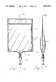
- FIG. 1 is an elevational view of a filled and ready to use flexible solution containers-and the attached port assembly according to the present invention
- FIG. 2 is a side view of the filled flexible solution container and the attached port assembly of FIG. 1;
- FIG. 3 is an elevational cross section view of the preferred embodiment of the flexible solution container and attached port assembly according to the present invention.
- FIG. 4 is an elevational cross section view of FIG. 3;
- FIG. 5 is a partial cross section of the assembled port system according to the present invention.
- FIG. 6 is a partial cross section similar to FIG. 5 showing the penetrator element of the port system in the activated condition and in position for fluid flow;
- FIG. 7A is a cross section view of the tubular port member according to the present invention.
- FIG. 7B is an elevational view of the port member of FIG. 7A;
- FIG. 7C is a side view of 7B
- FIG. 7D is an end view along line D--D of FIG. 7B;
- FIG. 7E is a sectional view along line E--E of FIG. 7C;
- FIG. 8A is a cross section view of the penetrator element according to the present invention.
- FIG. 8B is an elevational view of the penetrator element of FIG. 8A;
- FIG. 8C is a right side view of FIG. 8B;
- FIG. 8D is a left side view of FIG. 8B
- FIG. 8E is a top end view of FIG. 8B
- FIG. 9A is a partial cross section of the port assembly according to the present invention when activated by a center point spiking pin;
- FIG. 9B is an elevational plan view of a center point spiking pin
- FIG. 10A is a partial cross section of the port assembly according to the present invention when activated by a blunt spiking pin;
- FIG. 10B is an elevational view of a blunt spiking pin
- FIG. 11A is a partial cross section of the port assembly according to the present invention when activated by a beveled spiking pin;
- FIG. 11B is an elevational view of a beveled spiking pin
- FIG. 12 is a schematic depiction of a form, fill and seal packaging machine and sterile core that might be use to assemble the flexible solution container and port assembly according to the present invention.
- the flexible container is fabricated from a sheet of flexible, multiple-layer film, such as for example an extrusion laminated film or an adhesive laminated film.
- the laminated film has at least an inner bondable layer, the desired barrier layers, and an outer bondable layer.
- the port assembly components are molded of suitable materials that are attachable by a saddle flange to the outer film layer, preferably by a thermal bonding process.
- the flexible container is preferably manufactured by a form, fill and seal packaging machine 20 as schematically depicted in FIG. 12.
- the forming of the flexible container, the filling with a sterile solution and the sealing of the flexible container is performed in a sterile core environment 22 associated with the packaging machine.
- the product solution is sterilized outside of the sterile core.
- the product solution is maintained sterile as it is filled and sealed in the flexible container.
- the port assembly is pre-sterilized outside of the sterile core and attached to the flexible container in the sterile core.
- the packaged product is thus a sterile solution in a sterile container with an attached sterile port assembly that is suitable for medical use such as parenteral fluid administration.
- a multiple-layer film that is suitable for form, fill and seal processing into a flexible container is as follows.
- a multiple layer, extrusion laminated film has a bondable inside layer, a gas barrier layer, a thermal stability layer, appropriate bonding layers and bondable outside layer.
- the laminated film sheet is initially horizontally flat as it longitudinally enters the packaging machine.
- a longitudinal middle line hereafter referred to as the saddle line longitudinally divides the film sheet into substantially equal and mirror-image first and second portions.
- a plurality of discrete, outward (i.e. downward) extending fluid sumps 30 are formed generally along the saddle line, such that the longitude axis of the sump is coincident with the saddle line.
- the sump is created by a thermo-forming process.
- the relevant portion of the film is heated and permanently stretched outward.
- the sump preferably has a smooth interior radius.
- the sump can be formed by permanently stretching the film beyond recovery by applying heat and a forming mandrel from the inside layer, or by applying heat and drawing a vacuum from the outside surface, or a combination of these or other known thermoforming processes.
- First and second portions of the film sheet are then inwardly folded over the saddle line so as to form a U-shaped through.
- the bottom surface 40 of the trough includes the stretched fluid sump 30.
- the saddle flange of the port member is attached to the outside surface of the laminated film at the sump 30.
- the inner layer of the opposed first and second laminated film portions are sealed together along a first sealing line extending from and generally perpendicular to the bottom surface 40 so as to form a first transverse side seal 42.
- the inner layer is also sealed together along a second sealing line parallel to the first line, but an equal distant on the other side of the fluid sump so as to form a second transverse side seal 44.
- first side seal 42, the bottom surface 40 and the second side seal 44 form an open pouch.
- the pouch may optionally be flushed with a flushing agent if it is to be filled with an oxygen sensitive drug.
- a flushing agent if it is to be filled with an oxygen sensitive drug.
- the port assembly includes a rigid tubular member 50, a cylindrical penetrator element 60, and a cover member 80.
- the tubular port member 50 has a first 52 and second 54 open end and is molded preferably of a heat bondable medical grade plastic, preferably a similar if not the same material as the inner layer of the laminated film.
- the tubular port member 50 is preferably injection molded from an olefin.
- the tubular port member includes an integral and circumferential flange 56 that surrounds the first open end of the tubular port.
- the flange has a contoured face of the same longitudinal and latitudinal shape as the outward stretched fluid sump.
- the congruent face of the contoured flange is circumferentially sealed around the orifice of the first open end of the tubular port so that there is an annular fluid tight seal between the inner face of the flange and the outer surface of the film layer at the fluid sump.
- the second opened end 54 of the tubular port is provided with an access fitment 58 that doesn't leak when connected with most convention medical piercing pin connectors.
- a removable cover 80 preferably made of an injection molded material or a compression set resilient elastomer material, is provided for closing and maintaining the sterility of the second open end 54 of the tubular port.
- the pierceable diaphragm of the port assembly is the laminated film material of the flexible container itself, a mechanism to pierce the film sheet and penetrate the inner chamber must be provided.
- the diaphragm element is located near the second open end of the port system.
- the diaphragm element is located at the first open end of the port system. Since there is little in common among known piercing pins, a captive piercing mechanism or penetrator 60, which functions as a universal piercing pin adapter for most of the known pins, is specifically provided for the port system of the present invention.
- the cylindrical penetrator element 60 is slidably contained within the tubular port 50.
- the penetrator element is preferably molded of a polycarbonate material for example, and has a sharp, beveled end 62 for protruding beyond the circumferential flange so as to pierce the film sheet and penetrate the inner chamber.
- the sharp end of the penetrator element has a hollow chamber 64 forwardly opening onto the beveled face.
- At least one and preferably two fluid passageways are formed through the penetrator element from the sharp end for fluid communication with the penetrator hollow chamber 64.
- the primary passageway is a center throughbore 66 from the hollow chamber to the opposite end of the penetrator.
- the secondary passageway is a substantially longitudinally extended channel 68 along the cylindrical surface of the penetrator and connected radially to the hollow chamber 64.
- the tubular port member as shown in FIGS. 7A-7E includes a first 52 and second 54 open end.
- the port includes an integral circumferential flange 56 surrounding the first opening.
- the flange face is congruent with the stretched surface of the fluid sump 30 of the flexible container.
- the port assembly also includes a slidable cylindrical penetrator 60.
- the cylindrical penetrator has a hollow chamber 64 in the beveled end 62 at the first open end of the tubular member.
- the other, non-piercing end 70 of the sliding penetrator member is flat, as shown in the preferred embodiment.
- the penetrator could be symmetrical and have two beveled opposite ends for ease of assembly.
- the penetrator includes a primary fluid passage such as a center bore 66 from the hollow chamber in the beveled end 62 of the penetrator through the cylindrical body of the penetrator.
- a primary fluid passage such as a center bore 66 from the hollow chamber in the beveled end 62 of the penetrator through the cylindrical body of the penetrator.
- the penetrator 60 further includes a secondary longitudinal channel 68 substantially along the outer cylindrical surface of the penetrator. The channel is radially connected to the hollow chamber 64 at the beveled end of the penetrator by a radial connection passage.
- the penetrator also includes a protruding knob 72 that is initially keyed within a radial shoulder 74 on the inner surface of the tubular port member 50 for initially holding the penetrator in the inactive position.
- the knob is also preferable keyed to a longitudinal channel in the port member so as to prevent the penetrator from twisting as it is activated and inserted through the laminated film and into the inner chamber.
- a rotational change in orientation of the penetrator could orient the sharp end 62 of the penetrator near the side wall of the flexible container and thus increase the risk of an accidental pin puncture of the side wall of the flexible container.
- the preferred orientation of the beveled end 62 is shown in FIG. 3 and 4 for example.
- the second end 70 of the penetrator is able to adapt to any conventional piercing pin configuration. Fluid flow through the penetrator is assured by either the primary center throughbore 66 or the secondary longitudinal channel 68 along the outside cylindrical edge.
- the fluid sump 30 on the bottom surface of the flexible container and the flow passageways 66 and 68 in the penetrator 60 facilitates less residual solution remaining in the bottom of the flexible solution container. A greater percentage of the solution in the flexible container will be readily available for flow communication through the administration ports.
- the hollow chamber 64 in the beveled end 62 of the penetrator facilitates that any solution in the sump will be able to flow through either the center bore or the longitudinal channel of the penetrator to the access fitment and the administrator set.
- the fluid sump of the flexible container and the penetrator of the administration port facilitates more drainage of the medical solution than the currently known and used flexible containers.
- a sterile formed, filled and sealed packaging method will now be described with reference to FIG. 12.
- a continuous, longitudinal strip of multiple layer film 82 is provided in rolls 84 The film is unwound and sterilized according to a predetermined, continuous indexing movement.
- the film is continuously indexed and longitudinally moved through the sterile core 22 of the packaging line. With the film in a horizontal orientation a uniformally and outwardly stretched plurality of fluid sumps 30 are formed along the center portion of continuous film strip.
- One method of forming of the sumps 30 is to apply heat to the film and use the outward movement of a forming mandrel.
- An alternative method for uniformally and outwardly stretching discrete center portions of the film strip is to apply heat and a vacuum from the outside or bottom edge of the film strip.
- a rigid tubular port assembly 12 having a circumferential flange 56 at one end is attached to the sump 30, preferably by thermal bonding.
- the inner face of the flange is congruent with the outwardly stretched configuration of the fluid sumps to provide annular sealing around the orifice of the tubular port member.
- the relevant portion of the film at the sump is heated and the flange of the port member is heated and a circumferential seal is created around the flange member by application of a thermal bonding process.
- other bonding processes such as heat and pressure, ultrasonic welding, or even adhesive bonding could be used.
- the bottom surface 40 includes the sump and circumferentially sealed saddle flange and the two opposed portions of the inner layer of the multiple layer film define the side walls.
- a first portion of the opposed inside layers of the film strip are formed together in a first transverse side seal 42 that extends from the bottom surface 40 to the outer edge of the film strip.
- the transverse side seal is generally perpendicular to the bottom surface.
- a second portion of the opposed inside layer of the strip is formed together to form a second parallel transverse side seal 44 extending from the bottom surface 40 to the top edge.
- the first side seal 42, the bottom surface 40, and the second side seal 44 define an open pouch.
- the pouch is advanced along the packaging line and is optionally flushed with a flushing agent, such as N 2 to remove all the air from the pouch pocket as needed.
- a flushing agent such as N 2 to remove all the air from the pouch pocket as needed.
- a sterile solution is then metered through a filling nozzle into the pouch and displaces the flushing agent or sterile air as provided.
- the continuous strip of filled flexible containers can exit the sterile core.
- the film strips are cut coincident with (i.e. in the middle of) the first and second side seals 42 and 44 so as to divide the continuously formed, filled and sealed film strips into individual sealed containers.
- this cutting step may be performed inside the sterile core, it is preferable to perform cutting outside the core since scrap or particulate will not accumulate in the sterile core.
- the diaphragm of the port assembly 12 is the laminated flexible film, there is no lower permeability in the attached port system such as encountered in the previously known and described flexible containers. Thus there is no need for an overwrap material for the flexible container and port assembly of the present invention, nor is there a need for a terminal sterilization process. This invention thus allows new and previously sensitive solutions to be package in form, fill and sealed flexible containers.
Abstract
The present invention relates to a sterile form, filled and sealed flexible solution container and an attached port assembly that allows for the sterile dispensing of the solution.
Description
This is a division of U.S. patent application Ser. No. 08/041,797, filed Apr. 1, 1993 now U.S. Pat. No. 5,334,180.
The present invention relates to a sterile formed, filled and sealed flexible solution container with an attached administration port system and, in particular, to a sterile formed, filled and sealed flexible solution container and an attached sterile administration port assembly which allows for the sterile maintenance and delivery of a sterile medical solution.
Various foodstuffs, liquids and other degradable material can be sterilely packaged in pouch-type flexible containers made from webs of flexible film that are sealed together along the unconnected peripheral sides. This type of flexible packaging is commonly referred to as form, fill and seal packages. There are a number of advantages to these pouch-type flexible containers, including weight, durability and low cost to produce. To a lesser extent, a few medical solutions have been sterilely packaged in pouch-type flexible containers by form, fill and seal packaging machines.
One disadvantage of these pouch-type flexible containers for medical solution use is that it is difficult to make a sterile connection to the flexible container for drawing the contents in a sterile manner. The wall material of the container is flexible and without any rigidity. Thus, it is difficult to obtain a liquid tight and leakproof connection through the flexible wall using traditional medical connectors such as needles or piercing pins.
Traditionally, it has been necessary for flexible solution containers used for parenteral solutions to include rigid administration ports to facilitate sterile access to the solution. These pre-formed, rigid administration ports are often molded from a suitable medical grade plastic material. The usual considerations for the material used for the administration ports are the ease of molding and the ability to be securely bonded to the flexible film sheets. For example, a "boat" administration port may be sealed by many known thermal bonding processes between the opposed inner layers of two flexible film sheets so as to form a flexible solution container. Ultrasonic welding or solvent bonding may also be used to seal the boat port between the film layers.
The majority of flexible films used for flexible solution containers are monolayer PVC films. Recently, a few multiple-layer, extrusion or adhesive laminated films have been used in form, fill and seal packaging for producing flexible solution containers. The inner, solution contacting layer must be substantially inert to the solution. Also the inner layer of the film must be readily bondable to itself. Furthermore, the inner film layer must be compatible with any material used for attachable components, such as administration ports. The outer layer of the laminated film must be durable and also compatible with other materials that may contact or be attached to the outside surface. If neither the inner or outer layer has the desired solution maintaining and barrier characteristics, such as low moisture and/or oxygen permeability, additional film layers may be required between the inner and outer layers.
A primary disadvantage of known flexible solution containers assembled according to the above described boat port construction is that the port material typically has a higher oxygen permeability than the film material. In the known form, fill and seal flexible solution containers, the permeability characteristic of the port material is much greater than the similar characteristic for the laminated film used to make the flexible container. Thus, the administration port of known flexible solution containers is often the weakest part of the barrier characteristics. This factor becomes extremely important for certain medical solutions which are sensitive to oxygen or other penetrating gases, for example.
In the past, any of the above deficiencies has been overcome by overwrapping the flexible solution container and/or the administration ports, with an overwrap material. While this redundancy in packaging may provide the desired barrier characteristics, the overwrap material introduces two important disadvantages. First, there is the additional cost to fabricate and later dispose of the overwrap. Second, there is concern that extractables from the overwrap material may migrate into the contained solution during post filling procedures, such as during the sterilization process or even during shelf life.
Pre-formed rigid administration ports constitute potential places of leakage and are potential points of entry in an otherwise sealed, durable, flexible container. Moreover, the rigid ports make it more difficult to arrange an outer protective package around the flexible container. Also the protective overwrap only initially prevents the packaged solution from losing its potency due to evaporation or diffusion. When the overwrap is removed or breached, the administration ports positioned between two layers of film is an effective breach in the barrier characteristics of the flexible container for certain sensitive drugs.
For example, due to the sensitivity of certain solutions to oxygen, such as amino acids, it is desirable to use materials that minimize the permeation of oxygen for the flexible solution containers for parenteral administration of these solutions. The properties of the film can be controlled easily by the choice of the film components and structure. However, the oxygen permeation properties of the port system are not as easily controlled. Thus, it is desirable to use the film and its good barrier properties as both the solution contacting surface and the pierceable diaphragm of the administration port system so that the barrier properties of the port system are consistent with the barrier properties of the flexible container. However this consistency is not achieved in known flexible containers having pre-formed rigid port systems sealed between the film layers of the flexible container.
Moreover, the known flexible container and administration port systems often include an entry port in addition to the administration port. The entry ports are likewise inserted between film layers at the perimeter seal. Both ports are thus a breach through an otherwise effective perimeter barrier. A pierceable diaphragm is provided in the administration port to prevent an outflow of solution. During packaging, the flexible container may be filled through the entry port. After filling, the entry port is sealed, but the ports, and specifically the exposed port material, is the potential point of entry for compromising the barrier characteristics.
Flange ports are an alternative to boat ports and may be advantageously sealed to a film surface. However for the flexible solution container produced by the known form, fill and seal process, the use of flange ports does not remove the barrier deficiency. For example, a flexible parenteral solution container including a flange-sealed port assembly is disclosed in U.S. Pat. No. 4,695,337 to Christine and in U.S. Pat. No. 4779397 to Christine et al. A major disadvantage of the disclosed flexible solution container is that the flexible film barrier of the flexible container is purposefully breached during the assembly steps to mount and seal the administration port or fitment to the inside surface of the flexible container, as seen for example in FIGS. 4a-4d of the patents.
Thus, due to the inherent breaches in the film barriers for known flexible solution containers in current use, parenteral solutions may be subjected to degradation during the shelf life of the product solution. While an overwrap may provide some protection for the flexible container and the port administration system from contamination or degradation during shelf life, the overwrap introduces additional concerns that are increasingly desirable to avoid.
Thus, it is desirable to utilize the unbreached and completely intact film of the flexible solution container as the primary barrier for medical solutions packaged in flexible solution containers and especially for certain oxygen or other gas sensitive parenteral solutions.
It is therefore desirable to manufacture a flexible container that provides integral barrier characteristics without any compromises in the barrier characteristics of the film material used for the flexible solution container.
It is also desirable to manufacture a flexible container that includes an attached administration port system that is accessible by a variety of piercing pins, including center point pins, beveled pins and blunt pins as well as a port system that is compatible with the various lengths and other dimensions of the most common piercing pins.
It is also desirable to manufacture a flexible container that allows the maximum amount of solution to be readily, completely and easily delivered in a sterile manner from the container.
The present invention relates to a sterilely formed, sterilely filled, and sterilely sealed flexible solution container including a sheet of laminated flexible film folded over along a saddle line so that a portion of the inner surface of the sheet faces a second portion of the inner surface of the sheet. A continuous peripheral line of sealing contact along the perimeter of the facing portions of this sheet is provided so as to form an inner sealed chamber between the first and second facing portions of the film A rigid administration port including a tubular member having a first and second open end is provided for attachment to the outer surface of the flexible container. An integral circumferential flange surrounds the first open end of the tubular port and the flange is circumferentially sealed generally along the axis of a sump portion outwardly formed in the bottom surface of the flexible film of the formed, filled and sealed chamber. The integrity of the sealed chamber is not compromised by the attached tubular port. An access fitment is provided on the second open end of the tubular port and a removable cover for closing the second open end is provided. A penetrator element is slidably contained within the tubular port and has a contained sharp end for slidably protruding beyond the circumferential flange at the first open end of the tubular port member so as to pierce the film surface and penetrate the sealed chamber. At least one fluid passageway through the penetrator element from the pierced sealed chamber to the access fitment is provided.
More specifically, the present invention relates to an administration port for use with a formed, filled and sealed, flexible solution container. The port includes a rigid, tubular body having a first and second open end. A circumferential flange surrounds the first open end of the tubular body and is circumferentially sealable to the outer surface of the flexible container. An access fitment is provided at the second open end of the tubular body. A resilient or elastomeric cover is removably attached to the access fitment to initially close the second open end of the tubular body and maintain the sterile condition of the port system until used. A piercing mechanism or penetrator is provided in the administration administration port to initiate fluid flow communication from the sealed flexible container to the access fitment. In a preferred embodiment, the penetrator element includes a slidably cylindrical member initially wholly contained within the tubular body. The penetrator has a sharp end for slidably protruding beyond the circumferential flange so as to pierce the film forming the sealed inner chamber. The penetrator includes a hollow portion opening into the sharp beveled edge at the front end. A passageway is provided through the penetrator element from the pierced surface of the sealed container to the access fitment for sterile fluid flow of the solution from the flexible container.
The present invention is also directed to a sterile method for forming, filling and sealing a continuous, longitudinal strip of flexible laminated film into a plurality of individual flexible containers. The continuous film strip enters the sterile core and is sterilized and dried by any suitable sterilizing process. The flat, continuous film strip is continuously indexed through the sterile core. Next a plurality of center portions are outwardly stretched to form a plurality of discrete fluid sumps. The continuous film strip is then formed into a continuous U-shaped trough having a rounded bottom surface and two inside facing surfaces. Transverse portions of the sides surfaces are sealed together and with the bottom surface forms an open pocket. The pocket is filled with a separately separately sterilized solution and the top surface is sealed to form sealed chambers. As a final step, the continuous strip is cut coincident with each transverse seal so as to form individual flexible solution containers.
Other feature and advantages of the present invention will become readily apparent from the following detailed description, the accompanying drawings, and the appended claims.
FIG. 1 is an elevational view of a filled and ready to use flexible solution containers-and the attached port assembly according to the present invention;
FIG. 2 is a side view of the filled flexible solution container and the attached port assembly of FIG. 1;
FIG. 3 is an elevational cross section view of the preferred embodiment of the flexible solution container and attached port assembly according to the present invention;
FIG. 4 is an elevational cross section view of FIG. 3;
FIG. 5 is a partial cross section of the assembled port system according to the present invention;
FIG. 6 is a partial cross section similar to FIG. 5 showing the penetrator element of the port system in the activated condition and in position for fluid flow;
FIG. 7A is a cross section view of the tubular port member according to the present invention;
FIG. 7B is an elevational view of the port member of FIG. 7A;
FIG. 7C is a side view of 7B;
FIG. 7D is an end view along line D--D of FIG. 7B;
FIG. 7E is a sectional view along line E--E of FIG. 7C;
FIG. 8A is a cross section view of the penetrator element according to the present invention;
FIG. 8B is an elevational view of the penetrator element of FIG. 8A; FIG. 8C is a right side view of FIG. 8B;
FIG. 8D is a left side view of FIG. 8B;
FIG. 8E is a top end view of FIG. 8B;
FIG. 9A is a partial cross section of the port assembly according to the present invention when activated by a center point spiking pin;
FIG. 9B is an elevational plan view of a center point spiking pin;
FIG. 10A is a partial cross section of the port assembly according to the present invention when activated by a blunt spiking pin;
FIG. 10B is an elevational view of a blunt spiking pin;
FIG. 11A is a partial cross section of the port assembly according to the present invention when activated by a beveled spiking pin;
FIG. 11B is an elevational view of a beveled spiking pin; and
FIG. 12 is a schematic depiction of a form, fill and seal packaging machine and sterile core that might be use to assemble the flexible solution container and port assembly according to the present invention.
Referring now to FIGS. 1-2 and 3-4, a flexible solution container 10 and port assembly 12 for maintenance and delivery of a sterile medical solution is shown. The flexible container is fabricated from a sheet of flexible, multiple-layer film, such as for example an extrusion laminated film or an adhesive laminated film. The laminated film has at least an inner bondable layer, the desired barrier layers, and an outer bondable layer. The port assembly components are molded of suitable materials that are attachable by a saddle flange to the outer film layer, preferably by a thermal bonding process.
The flexible container is preferably manufactured by a form, fill and seal packaging machine 20 as schematically depicted in FIG. 12. The forming of the flexible container, the filling with a sterile solution and the sealing of the flexible container is performed in a sterile core environment 22 associated with the packaging machine. The product solution is sterilized outside of the sterile core. The product solution is maintained sterile as it is filled and sealed in the flexible container. The port assembly is pre-sterilized outside of the sterile core and attached to the flexible container in the sterile core. The packaged product is thus a sterile solution in a sterile container with an attached sterile port assembly that is suitable for medical use such as parenteral fluid administration.
An example of a multiple-layer film that is suitable for form, fill and seal processing into a flexible container is as follows. A multiple layer, extrusion laminated film has a bondable inside layer, a gas barrier layer, a thermal stability layer, appropriate bonding layers and bondable outside layer.
The laminated film sheet is initially horizontally flat as it longitudinally enters the packaging machine. A longitudinal middle line, hereafter referred to as the saddle line longitudinally divides the film sheet into substantially equal and mirror-image first and second portions.
A plurality of discrete, outward (i.e. downward) extending fluid sumps 30 are formed generally along the saddle line, such that the longitude axis of the sump is coincident with the saddle line. The sump is created by a thermo-forming process. The relevant portion of the film is heated and permanently stretched outward. The sump preferably has a smooth interior radius. The sump can be formed by permanently stretching the film beyond recovery by applying heat and a forming mandrel from the inside layer, or by applying heat and drawing a vacuum from the outside surface, or a combination of these or other known thermoforming processes.
First and second portions of the film sheet are then inwardly folded over the saddle line so as to form a U-shaped through. The bottom surface 40 of the trough includes the stretched fluid sump 30. The saddle flange of the port member is attached to the outside surface of the laminated film at the sump 30.
Referring now to FIG. 3 the inner layer of the opposed first and second laminated film portions are sealed together along a first sealing line extending from and generally perpendicular to the bottom surface 40 so as to form a first transverse side seal 42. The inner layer is also sealed together along a second sealing line parallel to the first line, but an equal distant on the other side of the fluid sump so as to form a second transverse side seal 44. Together the first side seal 42, the bottom surface 40 and the second side seal 44 form an open pouch.
The pouch may optionally be flushed with a flushing agent if it is to be filled with an oxygen sensitive drug. After the pouch is flushed and filled with the sterile solution, the top portion of the pouch is sealed together along a third sealing line 46 so as t o form a hermetically sealed inner chamber between the first and second laminated film portions.
Refering now to FIGS. 5-8, the port assembly includes a rigid tubular member 50, a cylindrical penetrator element 60, and a cover member 80. The tubular port member 50 has a first 52 and second 54 open end and is molded preferably of a heat bondable medical grade plastic, preferably a similar if not the same material as the inner layer of the laminated film. The tubular port member 50 is preferably injection molded from an olefin. The tubular port member includes an integral and circumferential flange 56 that surrounds the first open end of the tubular port. The flange has a contoured face of the same longitudinal and latitudinal shape as the outward stretched fluid sump. The congruent face of the contoured flange is circumferentially sealed around the orifice of the first open end of the tubular port so that there is an annular fluid tight seal between the inner face of the flange and the outer surface of the film layer at the fluid sump.
The second opened end 54 of the tubular port is provided with an access fitment 58 that doesn't leak when connected with most convention medical piercing pin connectors. A removable cover 80, preferably made of an injection molded material or a compression set resilient elastomer material, is provided for closing and maintaining the sterility of the second open end 54 of the tubular port.
Since the pierceable diaphragm of the port assembly according to the present invention is the laminated film material of the flexible container itself, a mechanism to pierce the film sheet and penetrate the inner chamber must be provided. In previously described flexible containers, the diaphragm element is located near the second open end of the port system. However, in the port system of the present invention, the diaphragm element is located at the first open end of the port system. Since there is little in common among known piercing pins, a captive piercing mechanism or penetrator 60, which functions as a universal piercing pin adapter for most of the known pins, is specifically provided for the port system of the present invention.
The cylindrical penetrator element 60 is slidably contained within the tubular port 50. The penetrator element is preferably molded of a polycarbonate material for example, and has a sharp, beveled end 62 for protruding beyond the circumferential flange so as to pierce the film sheet and penetrate the inner chamber. The sharp end of the penetrator element has a hollow chamber 64 forwardly opening onto the beveled face. At least one and preferably two fluid passageways are formed through the penetrator element from the sharp end for fluid communication with the penetrator hollow chamber 64. The primary passageway is a center throughbore 66 from the hollow chamber to the opposite end of the penetrator. The secondary passageway is a substantially longitudinally extended channel 68 along the cylindrical surface of the penetrator and connected radially to the hollow chamber 64. Thus the primary and secondary passageways provide fluid communication from the hollow chamber to the access port.
More specifically the tubular port member as shown in FIGS. 7A-7E includes a first 52 and second 54 open end. The port includes an integral circumferential flange 56 surrounding the first opening. The flange face is congruent with the stretched surface of the fluid sump 30 of the flexible container. The port assembly also includes a slidable cylindrical penetrator 60. The cylindrical penetrator has a hollow chamber 64 in the beveled end 62 at the first open end of the tubular member. Preferably the other, non-piercing end 70 of the sliding penetrator member is flat, as shown in the preferred embodiment. Alternatively, the penetrator could be symmetrical and have two beveled opposite ends for ease of assembly.
The penetrator includes a primary fluid passage such as a center bore 66 from the hollow chamber in the beveled end 62 of the penetrator through the cylindrical body of the penetrator. As best seen in FIGS. 8A and 8D, the penetrator 60 further includes a secondary longitudinal channel 68 substantially along the outer cylindrical surface of the penetrator. The channel is radially connected to the hollow chamber 64 at the beveled end of the penetrator by a radial connection passage.
The penetrator also includes a protruding knob 72 that is initially keyed within a radial shoulder 74 on the inner surface of the tubular port member 50 for initially holding the penetrator in the inactive position. The knob is also preferable keyed to a longitudinal channel in the port member so as to prevent the penetrator from twisting as it is activated and inserted through the laminated film and into the inner chamber. A rotational change in orientation of the penetrator could orient the sharp end 62 of the penetrator near the side wall of the flexible container and thus increase the risk of an accidental pin puncture of the side wall of the flexible container. The preferred orientation of the beveled end 62 is shown in FIG. 3 and 4 for example.
As shown in FIGS. 9, 10, and 11, the second end 70 of the penetrator is able to adapt to any conventional piercing pin configuration. Fluid flow through the penetrator is assured by either the primary center throughbore 66 or the secondary longitudinal channel 68 along the outside cylindrical edge.
The fluid sump 30 on the bottom surface of the flexible container and the flow passageways 66 and 68 in the penetrator 60 facilitates less residual solution remaining in the bottom of the flexible solution container. A greater percentage of the solution in the flexible container will be readily available for flow communication through the administration ports. The hollow chamber 64 in the beveled end 62 of the penetrator facilitates that any solution in the sump will be able to flow through either the center bore or the longitudinal channel of the penetrator to the access fitment and the administrator set. Thus the fluid sump of the flexible container and the penetrator of the administration port according to the present invention facilitates more drainage of the medical solution than the currently known and used flexible containers.
A sterile formed, filled and sealed packaging method will now be described with reference to FIG. 12. A continuous, longitudinal strip of multiple layer film 82 is provided in rolls 84 The film is unwound and sterilized according to a predetermined, continuous indexing movement.
The film is continuously indexed and longitudinally moved through the sterile core 22 of the packaging line. With the film in a horizontal orientation a uniformally and outwardly stretched plurality of fluid sumps 30 are formed along the center portion of continuous film strip. One method of forming of the sumps 30 is to apply heat to the film and use the outward movement of a forming mandrel. An alternative method for uniformally and outwardly stretching discrete center portions of the film strip is to apply heat and a vacuum from the outside or bottom edge of the film strip.
Once the film strip has been permanently stretched to form fluid sumps 30 along the saddle line of the film, a rigid tubular port assembly 12 having a circumferential flange 56 at one end is attached to the sump 30, preferably by thermal bonding. The inner face of the flange is congruent with the outwardly stretched configuration of the fluid sumps to provide annular sealing around the orifice of the tubular port member. Preferably the relevant portion of the film at the sump is heated and the flange of the port member is heated and a circumferential seal is created around the flange member by application of a thermal bonding process. Alternatively, other bonding processes such as heat and pressure, ultrasonic welding, or even adhesive bonding could be used.
With the port assembly 12 now firmly bonded to the outer face of the laminated film, the wings of the flat film sheet are formed or plowed into a continuous U-shaped trough so as to define the side walls of the container. The bottom surface 40 includes the sump and circumferentially sealed saddle flange and the two opposed portions of the inner layer of the multiple layer film define the side walls.
A first portion of the opposed inside layers of the film strip are formed together in a first transverse side seal 42 that extends from the bottom surface 40 to the outer edge of the film strip. The transverse side seal is generally perpendicular to the bottom surface. As the continuously indexing advances the film through the packaging line, a second portion of the opposed inside layer of the strip is formed together to form a second parallel transverse side seal 44 extending from the bottom surface 40 to the top edge. The first side seal 42, the bottom surface 40, and the second side seal 44 define an open pouch.
The pouch is advanced along the packaging line and is optionally flushed with a flushing agent, such as N2 to remove all the air from the pouch pocket as needed. A sterile solution is then metered through a filling nozzle into the pouch and displaces the flushing agent or sterile air as provided.
When the pouch is filled with the metered sterile solution, a third portion along the top of the folded film strip is sealed together to form a top seal 46 and thus complete the hermetically sealed flexible container containing the sterile solution. At t his point in the process, the continuous strip of filled flexible containers can exit the sterile core. Preferably the film strips are cut coincident with (i.e. in the middle of) the first and second side seals 42 and 44 so as to divide the continuously formed, filled and sealed film strips into individual sealed containers. Although this cutting step may be performed inside the sterile core, it is preferable to perform cutting outside the core since scrap or particulate will not accumulate in the sterile core.
Thus an individually sealed sterile container having a sterile port assembly and containing a sterile fluid is produced. Since all of the individual components, namely the film, the port assembly, and the sterile solution have been separately sterilized and are brought together in the sterile core, there is no need for further sterilization. This allows heat sensitive drugs, for example, to be package in flexible containers without degradation of the solution due to overheating during a traditional terminal sterilization process such as autoclaving.
Since the diaphragm of the port assembly 12 is the laminated flexible film, there is no lower permeability in the attached port system such as encountered in the previously known and described flexible containers. Thus there is no need for an overwrap material for the flexible container and port assembly of the present invention, nor is there a need for a terminal sterilization process. This invention thus allows new and previously sensitive solutions to be package in form, fill and sealed flexible containers.
While several embodiments of the invention have been described, modifications within the scope of the present invention may be readily apparent to one of ordinary skill in the art. All such modifications are intended to be covered by the scope of the accompanying claims.
Claims (9)
1. A method for forming, filling and sealing a continuous, longitudinal strip of flexible, multiple-layer film into a plurality of individual flexible solution containers, comprising the steps of:
sterilizing the continuous strip of film;
uniformly and outwardly stretching discrete center portions along the continuous strip of multiple-layer film to form a plurality of solution sumps;
providing a plurality of rigid tubular port members each having a circumferential flange at one end of the tubular port member, each circumferential flange having an inner flange face congruent with the outwardly stretched solution sumps of the multiple-layer film strip;
circumferentially sealing the inner flange face of the port member to the outside layer of the stretched solution sump of the multiple-layer film strip;
forming the multiple-layer film strip into a continuous U-shaped longitudinal trough having a bottom surface including the stretched solution sump and the circumferentially sealed flange and having two side surfaces including the opposed inside layer of the multiple-layer film strip;
sealing a first portion of the opposed inside layer of the film strip together to form a first transverse side seal extending from and generally perpendicular to the bottom surface;
sealing a second portion of the opposed inside layer of the film strip together to form a second parallel transverse side seal extending from and generally perpendicular to the bottom surface, so that the first side seal, the bottom surface and the second side seal define an open pouch;
filling the pouch with a sterile solution;
sealing a third portion of the inside layer of the film strip together to form a top seal so as to form a sealed flexible container; and
cutting the film strip coincident with the first and second side seals so as to divide the continuous formed, filled and sealed film strip into individual sealed containers.
2. The method for forming, filling and sealing a plurality of flexible solution containers in claim 1 wherein the outwardly stretched solution sumps of the film strip are uniformly formed by applying heat and a forming mandrel to the inside layer of the film strip.
3. The method for forming, filling and sealing a plurality of flexible solution containers in claim 1 wherein the outwardly stretched solution sumps of the film strip are uniformly formed by applying heat and a vacuum to the outside layer of the film strip.
4. The method in claim 1 wherein the pouch is flushed with a flushing agent prior to the filling step.
5. A method for forming, filling and sealing a flexible solution container, comprising the steps of:
providing a strip of flexible, multiple-layer film;
uniformly and outwardly stretching a discrete center portion of the film strip to form a solution sump;
providing a rigid tubular port member having a circumferential flange at one end, the flange having an inner flange face congruent with the outwardly stretched solution sump of the film strip;
circumferentially sealing the inner flange face of the port member to the outside layer of the stretched solution sump of the multiple-layer film strip;
further forming the multiple-layer film strip into a U-shaped trough having a bottom surface including the stretched solution sump and the circumferentially sealed flange and having two side surfaces including the opposed inside layer of the multiple-layer film strip;
sealing a first portion of the opposed inside layer of the film strip together to form a first transverse side seal extending from and generally perpendicular to the bottom surface;
sealing a second portion of the opposed inside layer of the film strip together to form a second parallel transverse side seal extending from and generally perpendicular to the bottom surface, so that the first side seal, the bottom surface and the second side seal define an open pouch;
filling the pouch with a sterile solution; and
sealing a third portion of the inside layer of the film strip together to form a sealed flexible container.
6. The method for forming, filling and sealing a flexible solution container in claim 5 wherein the outwardly stretched solution sump of the film strip is uniformly formed by applying heat and a forming mandrel to the inside layer of the film strip.
7. The method for forming, filling and sealing a flexible solution container in claim 5 wherein the outwardly stretched solution sump of the film strip is uniformly formed by applying heat and a vacuum to the outside layer of the film strip.
8. The method in claim 6 wherein the strip of film is sterilized before the center portion of the film strip is stretched to form the sump.
9. The method of claim 8 wherein the open pouch is flushed with a flushing agent prior to the filling step.
Priority Applications (1)
| Application Number | Priority Date | Filing Date | Title |
|---|---|---|---|
| US08/283,017 US5493845A (en) | 1993-04-01 | 1994-07-29 | Method for forming, filling and sealing a sterile flexible container |
Applications Claiming Priority (2)
| Application Number | Priority Date | Filing Date | Title |
|---|---|---|---|
| US08/041,797 US5334180A (en) | 1993-04-01 | 1993-04-01 | Sterile formed, filled and sealed flexible container |
| US08/283,017 US5493845A (en) | 1993-04-01 | 1994-07-29 | Method for forming, filling and sealing a sterile flexible container |
Related Parent Applications (1)
| Application Number | Title | Priority Date | Filing Date |
|---|---|---|---|
| US08/041,797 Division US5334180A (en) | 1993-04-01 | 1993-04-01 | Sterile formed, filled and sealed flexible container |
Publications (1)
| Publication Number | Publication Date |
|---|---|
| US5493845A true US5493845A (en) | 1996-02-27 |
Family
ID=21918371
Family Applications (2)
| Application Number | Title | Priority Date | Filing Date |
|---|---|---|---|
| US08/041,797 Expired - Fee Related US5334180A (en) | 1993-04-01 | 1993-04-01 | Sterile formed, filled and sealed flexible container |
| US08/283,017 Expired - Lifetime US5493845A (en) | 1993-04-01 | 1994-07-29 | Method for forming, filling and sealing a sterile flexible container |
Family Applications Before (1)
| Application Number | Title | Priority Date | Filing Date |
|---|---|---|---|
| US08/041,797 Expired - Fee Related US5334180A (en) | 1993-04-01 | 1993-04-01 | Sterile formed, filled and sealed flexible container |
Country Status (1)
| Country | Link |
|---|---|
| US (2) | US5334180A (en) |
Cited By (27)
| Publication number | Priority date | Publication date | Assignee | Title |
|---|---|---|---|---|
| US5664399A (en) * | 1994-05-09 | 1997-09-09 | Societe Imv -Instruments De Medecine Veterinaire | Tiltable table for packaging liquids, particularly animal semen, in flexible artificial insemination pouches |
| US5881535A (en) * | 1996-04-09 | 1999-03-16 | Baxter International, Inc. | Apparatus and method for filling and sealing intravenous solution bags |
| EP0957044A1 (en) * | 1998-05-11 | 1999-11-17 | Cryovac, Inc. | Easy opening system for shrunk hermetic bags |
| US6203535B1 (en) * | 1996-05-13 | 2001-03-20 | B. Braun Medical, Inc. | Method of making and using a flexible, multiple-compartment drug container |
| US6436341B1 (en) | 2001-01-16 | 2002-08-20 | Adroit Medical Systems, Inc. | Packaging system and method for packaging a sterilizable item to be flash sterilized |
| US6499598B2 (en) | 1999-11-15 | 2002-12-31 | Cryovac, Inc. | Easy opening system for shrunk hermetic bags |
| US20030000632A1 (en) * | 1996-05-13 | 2003-01-02 | Sperko William A. | Flexible medical container with selectively enlargeable compartments and method for making same |
| US6581357B1 (en) * | 1998-07-09 | 2003-06-24 | H. Obrist + Co. Ag | Method for attaching a shoulder element to a bag |
| US20030196411A1 (en) * | 2002-04-19 | 2003-10-23 | Schroeder Alfred A. | Flexible packaging |
| US6718735B2 (en) | 2002-03-19 | 2004-04-13 | Baxter International Inc. | Albumin in a flexible polymeric container |
| US20040083684A1 (en) * | 2002-11-06 | 2004-05-06 | Schroeder Alfred A. | Flexible packaging |
| US20040123883A1 (en) * | 2002-09-19 | 2004-07-01 | Afp Advanced Food Products Llc | Method and apparatus for producing fused tube on bag and bag produced thereby |
| US20040139697A1 (en) * | 2003-01-16 | 2004-07-22 | Balakrishna Reddy | Method for sealingly attaching a peripheral attachment member onto a filled-sealed pouch |
| US6955028B1 (en) * | 2001-07-03 | 2005-10-18 | Lendy Dunaway | Food container and methods of forming and using thereof |
| US20060138069A1 (en) * | 2004-12-23 | 2006-06-29 | John Domkowski | Port closure system for intravenous fluid container |
| US20070027437A1 (en) * | 2004-12-23 | 2007-02-01 | Burg Richard E | Medical fluid container with concave side weld |
| US20070119121A1 (en) * | 2005-11-28 | 2007-05-31 | Pdc Facilities, Inc. | Filling machine |
| US7527619B2 (en) | 2004-12-23 | 2009-05-05 | Hospira, Inc. | Medical fluid container |
| US20090320408A1 (en) * | 2008-06-30 | 2009-12-31 | Clifford Dey | Method and device for forming pre-made pouches |
| US20100089008A1 (en) * | 2006-03-14 | 2010-04-15 | Massimiliano Parini | Thermoforming Plant For The Blow Moulding And Heat-Welding Of Containers |
| US20100140127A1 (en) * | 2008-07-18 | 2010-06-10 | Adrian Maxwell William Smith | Bag of a heat-shrinkable gas-barrier thermoplastic film |
| US20100189831A1 (en) * | 2009-01-23 | 2010-07-29 | Proaseptic Technologies S.L.U. | Machine for horizontally manufacturing flexible sheet material packagings with outside chamber |
| US20100323641A1 (en) * | 2009-06-22 | 2010-12-23 | Qualcomm Incorporated | Method and apparatus for using pre-distortion and feedback to mitigate nonlinearity of circuits |
| US20110265429A1 (en) * | 2010-04-28 | 2011-11-03 | Marietta Corporation | System and Method for Assembly of Packettes Having Closures |
| US20180178938A1 (en) * | 2015-05-15 | 2018-06-28 | The Coca-Cola Company | System and method of in-line shaping, filling and enclosing to form product packaging |
| US10617603B2 (en) | 2016-01-22 | 2020-04-14 | Baxter International Inc. | Sterile solutions product bag |
| US11021275B2 (en) | 2016-01-22 | 2021-06-01 | Baxter International Inc. | Method and machine for producing sterile solution product bags |
Families Citing this family (80)
| Publication number | Priority date | Publication date | Assignee | Title |
|---|---|---|---|---|
| US5810398A (en) * | 1992-10-02 | 1998-09-22 | Pall Corporation | Fluid delivery systems and methods and assemblies for making connections |
| US5405333A (en) * | 1992-12-28 | 1995-04-11 | Richmond; Frank M. | Liquid medicament bag with needleless connector fitting using boat assembly |
| US5514123A (en) * | 1993-04-01 | 1996-05-07 | Abbott Laboratories | Sterile formed, filled and sealed flexible container |
| US6206860B1 (en) | 1993-07-28 | 2001-03-27 | Frank M. Richmond | Spikeless connection and drip chamber with valve |
| US5681284A (en) * | 1994-10-31 | 1997-10-28 | Glenn Herskowitz | Infusion pump with tube spike holder |
| US5755712A (en) * | 1994-12-22 | 1998-05-26 | Abbott Laboratories | Tamper evidence feature for sterile port and cap system |
| US5931820A (en) * | 1994-12-27 | 1999-08-03 | The United States Of America As Represented By The Secretary Of The Air Force | Wound and lavage irrigation connector apparatus and method for using |
| NL9500382A (en) * | 1995-02-27 | 1996-10-01 | Nutricia Nv | Enteral / parental substance administration system. |
| US5623969A (en) * | 1995-06-07 | 1997-04-29 | B. Braun Medical Inc. | Normally closed aspiration valve |
| US6391404B1 (en) | 1995-06-07 | 2002-05-21 | Baxter International Inc. | Coextruded multilayer film materials and containers made therefrom |
| US5569225A (en) * | 1995-06-29 | 1996-10-29 | Gkr Industries, Inc. | Bodily fluid test kit and method of testing bodily fluids |
| US5718383A (en) * | 1996-02-29 | 1998-02-17 | Par Way Group | Viscous liquid spray dispensing systems |
| WO1998000286A1 (en) | 1996-07-03 | 1998-01-08 | Baxter International Inc. | Method of sealing a port tube in a container |
| US5843540A (en) * | 1996-11-15 | 1998-12-01 | Tetra Laval Holdings & Finance, S.A. | Multi-layer flexible container for flowable materials |
| US6106502A (en) * | 1996-12-18 | 2000-08-22 | Richmond; Frank M. | IV sets with needleless fittings and valves |
| EP1716885A3 (en) | 1997-05-09 | 2006-11-15 | Pall Corporation | Connector assemblies, fluid systems, and methods for making a connection |
| US6394993B1 (en) * | 1997-05-21 | 2002-05-28 | Nestec, Ltd. | Protective spiking port, container implementing same and method for protecting a container |
| SE515113C2 (en) * | 1997-09-29 | 2001-06-11 | Asept Int Ab | Packaging, ways of making this and coupling for the same |
| US6019750A (en) | 1997-12-04 | 2000-02-01 | Baxter International Inc. | Sliding reconstitution device with seal |
| US6383210B1 (en) | 2000-06-02 | 2002-05-07 | Innercool Therapies, Inc. | Method for determining the effective thermal mass of a body or organ using cooling catheter |
| US6098844A (en) * | 1998-01-23 | 2000-08-08 | Kenneth Nicolle | Water dispensing system |
| US6585752B2 (en) | 1998-06-23 | 2003-07-01 | Innercool Therapies, Inc. | Fever regulation method and apparatus |
| US6719779B2 (en) | 2000-11-07 | 2004-04-13 | Innercool Therapies, Inc. | Circulation set for temperature-controlled catheter and method of using the same |
| US6006388A (en) * | 1998-04-14 | 1999-12-28 | Young; Cecil Blake | Dispenser for dispensing concentrated liquid soap to industrial cleaning apparatuses |
| US6179821B1 (en) * | 1998-06-18 | 2001-01-30 | Glenn A. Caspary | Membrane port for a container |
| US6053360A (en) * | 1998-07-01 | 2000-04-25 | Packaging Systems, Inc. | Fitment for a flexible container |
| AR021220A1 (en) | 1998-09-15 | 2002-07-03 | Baxter Int | CONNECTION DEVICE FOR ESTABLISHING A FLUID COMMUNICATION BETWEEN A FIRST CONTAINER AND A SECOND CONTAINER. |
| US7425209B2 (en) | 1998-09-15 | 2008-09-16 | Baxter International Inc. | Sliding reconstitution device for a diluent container |
| US6113583A (en) | 1998-09-15 | 2000-09-05 | Baxter International Inc. | Vial connecting device for a sliding reconstitution device for a diluent container |
| US6200300B1 (en) | 1998-11-18 | 2001-03-13 | David S. Smith Packaging Limited | Hangable container |
| US20050194060A1 (en) * | 2004-03-03 | 2005-09-08 | Vincent Houwaert | Peelable seal closure assembly |
| US7678097B1 (en) | 1999-11-12 | 2010-03-16 | Baxter International Inc. | Containers and methods for manufacturing same |
| US6719723B2 (en) | 2000-12-06 | 2004-04-13 | Innercool Therapies, Inc. | Multipurpose catheter assembly |
| US6652942B2 (en) * | 2001-01-08 | 2003-11-25 | Baxter International Inc. | Assembly for a flowable material container |
| US6869653B2 (en) * | 2001-01-08 | 2005-03-22 | Baxter International Inc. | Port tube closure assembly |
| SE523001C2 (en) * | 2002-07-09 | 2004-03-23 | Carmel Pharma Ab | Coupling component for transmitting medical substances, comprises connecting mechanism for releasable connection to second coupling component having further channel for creating coupling, where connecting mechanism is thread |
| US7175614B2 (en) * | 2002-10-17 | 2007-02-13 | Baxter International Inc. | Peelable seal |
| US7544191B2 (en) * | 2002-10-22 | 2009-06-09 | Baxter International Inc. | Formed, filled, sealed solution container, port and method for establishing flow between the container and an administration set |
| US7507226B2 (en) * | 2002-10-22 | 2009-03-24 | Baxter International Inc. | Access port with safety tab and fluid container employing same |
| US7942861B2 (en) * | 2002-10-22 | 2011-05-17 | Baxter International Inc. | Fluid container with access port and safety cap |
| US20050025393A1 (en) * | 2003-07-29 | 2005-02-03 | Aaron Heyniger | Bag apparatus |
| EP1697252A4 (en) * | 2003-10-23 | 2012-03-07 | Internat Packaging Innovations Llc | Container adapted to hold and dispense bagged fluids |
| US7641851B2 (en) | 2003-12-23 | 2010-01-05 | Baxter International Inc. | Method and apparatus for validation of sterilization process |
| US8276793B2 (en) * | 2004-01-12 | 2012-10-02 | Nova Biomedical Corporation | Fitment for flexible container |
| US7254848B2 (en) * | 2004-04-01 | 2007-08-14 | Encon Safety Products, Inc. | Emergency eye wash system |
| US20070036471A1 (en) * | 2005-08-11 | 2007-02-15 | George Anasis | Freestanding upright mounted storage bag with grip for inverted application |
| US7665894B2 (en) * | 2005-09-26 | 2010-02-23 | Scholle Corporation | Flexible bag having a handle which facilitates hanging from a plurality of different outside structures |
| US20070089231A1 (en) * | 2005-10-24 | 2007-04-26 | Fendall, Inc. | Emergency eyewash station having a peircing mechanism to puncture a sealed fluid bladder |
| WO2007050524A1 (en) * | 2005-10-24 | 2007-05-03 | Sperian Eye & Face Protection, Inc. | Pump assembly for an emergency eyewash station |
| US8316477B2 (en) * | 2005-10-24 | 2012-11-27 | Sperian Eye & Face Protection, Inc. | Cartridge assembly for a self-contained emergency eyewash station |
| US20070089234A1 (en) * | 2005-10-24 | 2007-04-26 | Fendall, Inc. | Emergency eyewash station having an integrated head rest |
| US8435220B2 (en) * | 2005-10-24 | 2013-05-07 | Sperian Eye and Face Protection, Inc. a Delaware corporation | Emergency eyewash station having an expandable bellows waste collection system |
| CH698008B1 (en) * | 2005-11-25 | 2009-04-30 | Belcap Switzerland Ag | A sealed fluid bag with welded drinking or dispensing nozzle. |
| US7607555B2 (en) * | 2006-03-01 | 2009-10-27 | Ds Smith Plastics Limited | Puncturable cap and piercer |
| WO2007106847A2 (en) * | 2006-03-15 | 2007-09-20 | Sperian Eye & Face Protection, Inc. | Emergency eyewash station and dispensing structure therefor |
| US9004761B2 (en) | 2006-05-01 | 2015-04-14 | Baxter International Inc. | Multiple chamber container with mistake proof administration system |
| CA2604433A1 (en) * | 2006-10-06 | 2008-04-06 | Tyco Healthcare Group Lp | Medical device package including self-puncturable port |
| US20090095766A1 (en) * | 2007-10-10 | 2009-04-16 | Jerry Trainello | Hands-free lid removal |
| US20090105684A1 (en) * | 2007-10-23 | 2009-04-23 | Baxter International Inc. | Medication port for medical fluid container |
| US8172823B2 (en) * | 2008-07-03 | 2012-05-08 | Baxter International Inc. | Port assembly for use with needleless connector |
| US7905873B2 (en) * | 2008-07-03 | 2011-03-15 | Baxter International Inc. | Port assembly for use with needleless connector |
| US8062280B2 (en) * | 2008-08-19 | 2011-11-22 | Baxter Healthcare S.A. | Port assembly for use with needleless connector |
| US8752734B2 (en) | 2009-02-11 | 2014-06-17 | Ds Smith Plastics Limited | Disposable assembly for a reusable urn or vessel |
| US8628509B2 (en) * | 2009-05-11 | 2014-01-14 | Abbott Laboratories | Enteral connectors and systems |
| US8394080B2 (en) * | 2009-05-14 | 2013-03-12 | Baxter International Inc. | Needleless connector with slider |
| US8348509B2 (en) * | 2009-09-10 | 2013-01-08 | Smart Bottle, Inc. | Flexible container with fitment and handle |
| WO2011031343A1 (en) * | 2009-09-10 | 2011-03-17 | Smart Bottle Inc. | Flexible container having flexible handles |
| US8454059B2 (en) | 2010-09-13 | 2013-06-04 | Pall Corporation | Connector assemblies, fluid systems including connector assemblies, and procedures for making fluid connections |
| US8695851B2 (en) * | 2010-09-15 | 2014-04-15 | Fres-Co System Usa, Inc. | External fitment with anti-flow blocking feature for aseptic package and method of use |
| US9612230B2 (en) | 2011-06-21 | 2017-04-04 | Miura Co., Ltd. | Water quality measuring device |
| JP5919658B2 (en) * | 2011-06-21 | 2016-05-18 | 三浦工業株式会社 | Drug package |
| FR2995789A1 (en) * | 2012-09-25 | 2014-03-28 | Pharmadyne | USE OF A PRE-AMPLIFIED POCKET IN AMBULATORY INFUSION |
| US20140261854A1 (en) * | 2013-03-13 | 2014-09-18 | Illinois Tool Works, Inc. | Bag in box dispensing container |
| US10561272B2 (en) * | 2013-11-05 | 2020-02-18 | Plascon Packaging, Inc. | Selectively sealable liner for a vessel |
| US10051990B2 (en) | 2013-11-05 | 2018-08-21 | Plascon Group | Liner for a vessel |
| US10227227B2 (en) | 2013-11-05 | 2019-03-12 | Plascon Group | Liner for a vessel |
| US10500132B2 (en) * | 2015-01-07 | 2019-12-10 | Dr. Py Instittue, Llc | Pouch with sealed fitment and method |
| US10160583B2 (en) | 2015-05-27 | 2018-12-25 | Ds Smith Plastics Limited | Co-injection molded dispensing components |
| GB2590002B (en) | 2015-08-28 | 2022-02-16 | Corplex Plastics Uk Ltd | Liner for a vessel |
| US10112820B1 (en) | 2016-01-19 | 2018-10-30 | Dss Rapak, Inc. | Beverage dispensing system with disposable liner and faucet |
Citations (5)
| Publication number | Priority date | Publication date | Assignee | Title |
|---|---|---|---|---|
| US3244576A (en) * | 1963-02-04 | 1966-04-05 | Thermoplastic Ind Inc | Apparatus for manufacturing flexible bags with nozzle |
| US4313904A (en) * | 1979-12-26 | 1982-02-02 | Abbott Laboratories | Method of manufacturing a flexible container with integral ports and diaphragm |
| US4470240A (en) * | 1976-10-06 | 1984-09-11 | Torterotot Roland | Production of sterile packages |
| US4512136A (en) * | 1982-08-23 | 1985-04-23 | Trinity Associates, A Partnership Of The State Of Pennsylvania | Fitment attachment methods in horizontal form/fill/seal machines |
| US4718215A (en) * | 1985-11-27 | 1988-01-12 | Baxter Travenol Laboratories, Inc. | Apparatus and method for attaching fitments to flexible containers |
Family Cites Families (12)
| Publication number | Priority date | Publication date | Assignee | Title |
|---|---|---|---|---|
| US2726656A (en) * | 1952-10-21 | 1955-12-13 | Compule Corp | Hypodermic syringe structure |
| US3509879A (en) * | 1967-11-24 | 1970-05-05 | American Hospital Supply Corp | Parenteral liquid container having frangible part structure |
| AR205565A1 (en) * | 1974-04-29 | 1976-05-14 | Abbott Lab | STORAGE AND TRANSFER UNIT FOR AN ADDITIVE PARTICULARLY APPLICABLE TO TRANSFER OF MEDICINES |
| US3986507A (en) * | 1975-04-16 | 1976-10-19 | Inpaco | Parenteral container |
| US4195632A (en) * | 1978-05-03 | 1980-04-01 | Cutter Laboratories, Inc. | Fluid flow valve |
| US4381776A (en) * | 1980-06-20 | 1983-05-03 | Haemonetics Corporation | Anticoagulant dispensing apparatus and method of use |
| US4411662A (en) * | 1982-04-06 | 1983-10-25 | Baxter Travenol Laboratories, Inc. | Sterile coupling |
| US4686125A (en) * | 1984-09-28 | 1987-08-11 | Baxter Travenol Laboratories, Inc. | Film laminate for sterile flexible containers |
| US4650452A (en) * | 1985-04-29 | 1987-03-17 | Squibb Corporation | Method for joining a tube to a collection pouch |
| US4781679A (en) * | 1986-06-12 | 1988-11-01 | Abbott Laboratories | Container system with integral second substance storing and dispensing means |
| US5176673A (en) * | 1988-06-02 | 1993-01-05 | Piero Marrucchi | Method and device for manipulating and transferring products between confined volumes |
| US5098202A (en) * | 1989-05-11 | 1992-03-24 | Baxter International Inc. | Multi-layer web of film having a gas barrier |
-
1993
- 1993-04-01 US US08/041,797 patent/US5334180A/en not_active Expired - Fee Related
-
1994
- 1994-07-29 US US08/283,017 patent/US5493845A/en not_active Expired - Lifetime
Patent Citations (5)
| Publication number | Priority date | Publication date | Assignee | Title |
|---|---|---|---|---|
| US3244576A (en) * | 1963-02-04 | 1966-04-05 | Thermoplastic Ind Inc | Apparatus for manufacturing flexible bags with nozzle |
| US4470240A (en) * | 1976-10-06 | 1984-09-11 | Torterotot Roland | Production of sterile packages |
| US4313904A (en) * | 1979-12-26 | 1982-02-02 | Abbott Laboratories | Method of manufacturing a flexible container with integral ports and diaphragm |
| US4512136A (en) * | 1982-08-23 | 1985-04-23 | Trinity Associates, A Partnership Of The State Of Pennsylvania | Fitment attachment methods in horizontal form/fill/seal machines |
| US4718215A (en) * | 1985-11-27 | 1988-01-12 | Baxter Travenol Laboratories, Inc. | Apparatus and method for attaching fitments to flexible containers |
Cited By (53)
| Publication number | Priority date | Publication date | Assignee | Title |
|---|---|---|---|---|
| US5664399A (en) * | 1994-05-09 | 1997-09-09 | Societe Imv -Instruments De Medecine Veterinaire | Tiltable table for packaging liquids, particularly animal semen, in flexible artificial insemination pouches |
| US5881535A (en) * | 1996-04-09 | 1999-03-16 | Baxter International, Inc. | Apparatus and method for filling and sealing intravenous solution bags |
| US6203535B1 (en) * | 1996-05-13 | 2001-03-20 | B. Braun Medical, Inc. | Method of making and using a flexible, multiple-compartment drug container |
| US20040068960A1 (en) * | 1996-05-13 | 2004-04-15 | Smith Steven L. | Flexible multi-compartment container with peelable seals and method for making same |
| US6468377B1 (en) | 1996-05-13 | 2002-10-22 | B. Braun Medical Inc. | Flexible medical container with selectively enlargeable compartments and method for making same |
| US6764567B2 (en) | 1996-05-13 | 2004-07-20 | B. Braun Medical | Flexible medical container with selectively enlargeable compartments and method for making same |
| US20030000632A1 (en) * | 1996-05-13 | 2003-01-02 | Sperko William A. | Flexible medical container with selectively enlargeable compartments and method for making same |
| EP0957044A1 (en) * | 1998-05-11 | 1999-11-17 | Cryovac, Inc. | Easy opening system for shrunk hermetic bags |
| US6581357B1 (en) * | 1998-07-09 | 2003-06-24 | H. Obrist + Co. Ag | Method for attaching a shoulder element to a bag |
| US6499598B2 (en) | 1999-11-15 | 2002-12-31 | Cryovac, Inc. | Easy opening system for shrunk hermetic bags |
| US6436341B1 (en) | 2001-01-16 | 2002-08-20 | Adroit Medical Systems, Inc. | Packaging system and method for packaging a sterilizable item to be flash sterilized |
| US7886505B1 (en) | 2001-07-03 | 2011-02-15 | Lendy Dunaway | Food container and methods of forming and using thereof |
| US6955028B1 (en) * | 2001-07-03 | 2005-10-18 | Lendy Dunaway | Food container and methods of forming and using thereof |
| US6718735B2 (en) | 2002-03-19 | 2004-04-13 | Baxter International Inc. | Albumin in a flexible polymeric container |
| US20040159574A1 (en) * | 2002-03-19 | 2004-08-19 | Lewis James D. | Albumin in a flexible polymeric container |
| US20040206055A1 (en) * | 2002-04-19 | 2004-10-21 | Schroeder Alfred A. | Flexible packaging |
| US20030196411A1 (en) * | 2002-04-19 | 2003-10-23 | Schroeder Alfred A. | Flexible packaging |
| US7600360B2 (en) | 2002-04-19 | 2009-10-13 | Lancer Partnership Ltd, Dorothy Linda Schroeder as Trustee for three trusts, and SMJCGF, LLP | Flexible packaging |
| US20040123883A1 (en) * | 2002-09-19 | 2004-07-01 | Afp Advanced Food Products Llc | Method and apparatus for producing fused tube on bag and bag produced thereby |
| US20040083684A1 (en) * | 2002-11-06 | 2004-05-06 | Schroeder Alfred A. | Flexible packaging |
| US6968669B2 (en) | 2002-11-06 | 2005-11-29 | Lancer Partnership Ltd. | Flexible packaging |
| US20040139697A1 (en) * | 2003-01-16 | 2004-07-22 | Balakrishna Reddy | Method for sealingly attaching a peripheral attachment member onto a filled-sealed pouch |
| US6996950B2 (en) * | 2003-01-16 | 2006-02-14 | Nestec S.A. | Method for sealingly attaching a peripheral attachment member onto a filled-sealed pouch |
| US7527619B2 (en) | 2004-12-23 | 2009-05-05 | Hospira, Inc. | Medical fluid container |
| US8136330B2 (en) | 2004-12-23 | 2012-03-20 | Hospira, Inc. | Medical fluid container |
| US7488311B2 (en) | 2004-12-23 | 2009-02-10 | Hospira, Inc. | Port closure system for intravenous fluid container |
| US8034041B2 (en) | 2004-12-23 | 2011-10-11 | Hospira, Inc. | Port closure system for intravenous fluid container |
| US7530974B2 (en) | 2004-12-23 | 2009-05-12 | Hospira, Inc. | Port closure system for intravenous fluid container |
| US20090192484A1 (en) * | 2004-12-23 | 2009-07-30 | Hospira, Inc. | Port closure system for intravenous fluid container |
| US20090209934A1 (en) * | 2004-12-23 | 2009-08-20 | Hospira, Inc. | Port closure system for intravenous fluid container |
| US20090235619A1 (en) * | 2004-12-23 | 2009-09-24 | Hospira, Inc. | Medical fluid container |
| US20070027437A1 (en) * | 2004-12-23 | 2007-02-01 | Burg Richard E | Medical fluid container with concave side weld |
| US8034042B2 (en) | 2004-12-23 | 2011-10-11 | Hospira, Inc. | Port closure system for intravenous fluid container |
| US20060138069A1 (en) * | 2004-12-23 | 2006-06-29 | John Domkowski | Port closure system for intravenous fluid container |
| US7717897B2 (en) | 2004-12-23 | 2010-05-18 | Hospira, Inc. | Medical fluid container with concave side weld |
| US7484345B2 (en) | 2005-11-28 | 2009-02-03 | Pdc Facilities, Inc. | Filling machine |
| US20070119121A1 (en) * | 2005-11-28 | 2007-05-31 | Pdc Facilities, Inc. | Filling machine |
| US20100089008A1 (en) * | 2006-03-14 | 2010-04-15 | Massimiliano Parini | Thermoforming Plant For The Blow Moulding And Heat-Welding Of Containers |
| US8758669B2 (en) | 2008-06-30 | 2014-06-24 | Ethicon, Inc. | Method and device for forming pre-made pouches |
| US8128859B2 (en) | 2008-06-30 | 2012-03-06 | Ethicon, Inc. | Method for forming pre-made pouches |
| US20090320408A1 (en) * | 2008-06-30 | 2009-12-31 | Clifford Dey | Method and device for forming pre-made pouches |
| US20100314805A1 (en) * | 2008-06-30 | 2010-12-16 | Clifford Dey | Method and device for forming pre-made pouches |
| US8021049B2 (en) | 2008-07-18 | 2011-09-20 | Cryovac, Inc. | Bag of a heat-shrinkable gas-barrier thermoplastic film |
| US20100140127A1 (en) * | 2008-07-18 | 2010-06-10 | Adrian Maxwell William Smith | Bag of a heat-shrinkable gas-barrier thermoplastic film |
| US20100189831A1 (en) * | 2009-01-23 | 2010-07-29 | Proaseptic Technologies S.L.U. | Machine for horizontally manufacturing flexible sheet material packagings with outside chamber |
| US8176711B2 (en) * | 2009-01-23 | 2012-05-15 | Proaseptic Technologies S.L.U. | Machine for horizontally manufacturing flexible sheet material packagings with outside chamber |
| US20100323641A1 (en) * | 2009-06-22 | 2010-12-23 | Qualcomm Incorporated | Method and apparatus for using pre-distortion and feedback to mitigate nonlinearity of circuits |
| US20110265429A1 (en) * | 2010-04-28 | 2011-11-03 | Marietta Corporation | System and Method for Assembly of Packettes Having Closures |
| US20180178938A1 (en) * | 2015-05-15 | 2018-06-28 | The Coca-Cola Company | System and method of in-line shaping, filling and enclosing to form product packaging |
| US10617603B2 (en) | 2016-01-22 | 2020-04-14 | Baxter International Inc. | Sterile solutions product bag |
| US11021275B2 (en) | 2016-01-22 | 2021-06-01 | Baxter International Inc. | Method and machine for producing sterile solution product bags |
| US11564867B2 (en) | 2016-01-22 | 2023-01-31 | Baxter International Inc. | Sterile solutions product bag |
| US11623773B2 (en) | 2016-01-22 | 2023-04-11 | Baxter International Inc. | Method and machine for producing sterile solution product bags |
Also Published As
| Publication number | Publication date |
|---|---|
| US5334180A (en) | 1994-08-02 |
Similar Documents
| Publication | Publication Date | Title |
|---|---|---|
| US5493845A (en) | Method for forming, filling and sealing a sterile flexible container | |
| US5514123A (en) | Sterile formed, filled and sealed flexible container | |
| US6280431B1 (en) | Sterile formed, filled and sealed flexible container and draining administration port therefor | |
| US4629080A (en) | Container such as a nursing container, having formed enclosure chamber for a dispensing member | |
| US7717897B2 (en) | Medical fluid container with concave side weld | |
| US4496362A (en) | Container for liquids for use in medicine and surgery | |
| KR100602485B1 (en) | Sterile connector for containers which contain medicinal liquids | |
| US4596573A (en) | Container | |
| US6162205A (en) | Container for therapeutic use | |
| US4553971A (en) | Pouch-like bags for containing liquids | |
| EP3654909B1 (en) | Sterile product bag with filtered port | |
| EP2136862A1 (en) | Storage container | |
| US3938519A (en) | Medical liquid container with a toggle film leak tester and method of leak testing with same | |
| JP4316718B2 (en) | Infusion container | |
| JP2000107257A (en) | Transfusion bag | |
| JP2004181065A (en) | Infusion solution bag package | |
| JP4366131B2 (en) | Multi-chamber container | |
| JP3839624B2 (en) | Multi-chamber container | |
| JP4775876B2 (en) | Method for producing medical container and medical container | |
| AU2007265010B2 (en) | Medical fluid container | |
| CA1205783A (en) | Storage bag | |
| JPH09108302A (en) | Medical container and its manufacture | |
| JPH10328269A (en) | Medical container | |
| JPH09108301A (en) | Medical container and its manufacture | |
| MXPA01000367A (en) | Sterile connector for containers which contain medicinal liquids |
Legal Events
| Date | Code | Title | Description |
|---|---|---|---|
| STCF | Information on status: patent grant |
Free format text: PATENTED CASE |
|
| CC | Certificate of correction | ||
| FPAY | Fee payment |
Year of fee payment: 4 |
|
| FPAY | Fee payment |
Year of fee payment: 8 |
|
| FPAY | Fee payment |
Year of fee payment: 12 |