US5493339A - System and method for transmitting a plurality of digital services including compressed imaging services and associated ancillary data services - Google Patents
System and method for transmitting a plurality of digital services including compressed imaging services and associated ancillary data services Download PDFInfo
- Publication number
- US5493339A US5493339A US08/160,828 US16082893A US5493339A US 5493339 A US5493339 A US 5493339A US 16082893 A US16082893 A US 16082893A US 5493339 A US5493339 A US 5493339A
- Authority
- US
- United States
- Prior art keywords
- data
- video
- vbi
- signal
- interface
- Prior art date
- Legal status (The legal status is an assumption and is not a legal conclusion. Google has not performed a legal analysis and makes no representation as to the accuracy of the status listed.)
- Expired - Lifetime
Links
Images


Classifications
-
- H—ELECTRICITY
- H04—ELECTRIC COMMUNICATION TECHNIQUE
- H04N—PICTORIAL COMMUNICATION, e.g. TELEVISION
- H04N7/00—Television systems
- H04N7/08—Systems for the simultaneous or sequential transmission of more than one television signal, e.g. additional information signals, the signals occupying wholly or partially the same frequency band, e.g. by time division
- H04N7/087—Systems for the simultaneous or sequential transmission of more than one television signal, e.g. additional information signals, the signals occupying wholly or partially the same frequency band, e.g. by time division with signal insertion during the vertical blanking interval only
- H04N7/088—Systems for the simultaneous or sequential transmission of more than one television signal, e.g. additional information signals, the signals occupying wholly or partially the same frequency band, e.g. by time division with signal insertion during the vertical blanking interval only the inserted signal being digital
- H04N7/0884—Systems for the simultaneous or sequential transmission of more than one television signal, e.g. additional information signals, the signals occupying wholly or partially the same frequency band, e.g. by time division with signal insertion during the vertical blanking interval only the inserted signal being digital for the transmission of additional display-information, e.g. menu for programme or channel selection
-
- H—ELECTRICITY
- H04—ELECTRIC COMMUNICATION TECHNIQUE
- H04N—PICTORIAL COMMUNICATION, e.g. TELEVISION
- H04N11/00—Colour television systems
- H04N11/04—Colour television systems using pulse code modulation
-
- H—ELECTRICITY
- H04—ELECTRIC COMMUNICATION TECHNIQUE
- H04N—PICTORIAL COMMUNICATION, e.g. TELEVISION
- H04N11/00—Colour television systems
- H04N11/04—Colour television systems using pulse code modulation
- H04N11/042—Codec means
-
- H—ELECTRICITY
- H04—ELECTRIC COMMUNICATION TECHNIQUE
- H04N—PICTORIAL COMMUNICATION, e.g. TELEVISION
- H04N11/00—Colour television systems
- H04N11/06—Transmission systems characterised by the manner in which the individual colour picture signal components are combined
- H04N11/12—Transmission systems characterised by the manner in which the individual colour picture signal components are combined using simultaneous signals only
- H04N11/14—Transmission systems characterised by the manner in which the individual colour picture signal components are combined using simultaneous signals only in which one signal, modulated in phase and amplitude, conveys colour information and a second signal conveys brightness information, e.g. NTSC-system
- H04N11/143—Encoding means therefor
-
- H—ELECTRICITY
- H04—ELECTRIC COMMUNICATION TECHNIQUE
- H04N—PICTORIAL COMMUNICATION, e.g. TELEVISION
- H04N11/00—Colour television systems
- H04N11/06—Transmission systems characterised by the manner in which the individual colour picture signal components are combined
- H04N11/12—Transmission systems characterised by the manner in which the individual colour picture signal components are combined using simultaneous signals only
- H04N11/14—Transmission systems characterised by the manner in which the individual colour picture signal components are combined using simultaneous signals only in which one signal, modulated in phase and amplitude, conveys colour information and a second signal conveys brightness information, e.g. NTSC-system
- H04N11/16—Transmission systems characterised by the manner in which the individual colour picture signal components are combined using simultaneous signals only in which one signal, modulated in phase and amplitude, conveys colour information and a second signal conveys brightness information, e.g. NTSC-system the chrominance signal alternating in phase, e.g. PAL-system
- H04N11/162—Encoding means therefor
-
- H—ELECTRICITY
- H04—ELECTRIC COMMUNICATION TECHNIQUE
- H04N—PICTORIAL COMMUNICATION, e.g. TELEVISION
- H04N21/00—Selective content distribution, e.g. interactive television or video on demand [VOD]
- H04N21/40—Client devices specifically adapted for the reception of or interaction with content, e.g. set-top-box [STB]; Operations thereof
- H04N21/41—Structure of client; Structure of client peripherals
- H04N21/426—Internal components of the client ; Characteristics thereof
-
- H—ELECTRICITY
- H04—ELECTRIC COMMUNICATION TECHNIQUE
- H04N—PICTORIAL COMMUNICATION, e.g. TELEVISION
- H04N21/00—Selective content distribution, e.g. interactive television or video on demand [VOD]
- H04N21/40—Client devices specifically adapted for the reception of or interaction with content, e.g. set-top-box [STB]; Operations thereof
- H04N21/43—Processing of content or additional data, e.g. demultiplexing additional data from a digital video stream; Elementary client operations, e.g. monitoring of home network or synchronising decoder's clock; Client middleware
- H04N21/4302—Content synchronisation processes, e.g. decoder synchronisation
- H04N21/4307—Synchronising the rendering of multiple content streams or additional data on devices, e.g. synchronisation of audio on a mobile phone with the video output on the TV screen
- H04N21/43072—Synchronising the rendering of multiple content streams or additional data on devices, e.g. synchronisation of audio on a mobile phone with the video output on the TV screen of multiple content streams on the same device
-
- H—ELECTRICITY
- H04—ELECTRIC COMMUNICATION TECHNIQUE
- H04N—PICTORIAL COMMUNICATION, e.g. TELEVISION
- H04N21/00—Selective content distribution, e.g. interactive television or video on demand [VOD]
- H04N21/40—Client devices specifically adapted for the reception of or interaction with content, e.g. set-top-box [STB]; Operations thereof
- H04N21/43—Processing of content or additional data, e.g. demultiplexing additional data from a digital video stream; Elementary client operations, e.g. monitoring of home network or synchronising decoder's clock; Client middleware
- H04N21/434—Disassembling of a multiplex stream, e.g. demultiplexing audio and video streams, extraction of additional data from a video stream; Remultiplexing of multiplex streams; Extraction or processing of SI; Disassembling of packetised elementary stream
- H04N21/4347—Demultiplexing of several video streams
-
- H—ELECTRICITY
- H04—ELECTRIC COMMUNICATION TECHNIQUE
- H04N—PICTORIAL COMMUNICATION, e.g. TELEVISION
- H04N21/00—Selective content distribution, e.g. interactive television or video on demand [VOD]
- H04N21/40—Client devices specifically adapted for the reception of or interaction with content, e.g. set-top-box [STB]; Operations thereof
- H04N21/43—Processing of content or additional data, e.g. demultiplexing additional data from a digital video stream; Elementary client operations, e.g. monitoring of home network or synchronising decoder's clock; Client middleware
- H04N21/434—Disassembling of a multiplex stream, e.g. demultiplexing audio and video streams, extraction of additional data from a video stream; Remultiplexing of multiplex streams; Extraction or processing of SI; Disassembling of packetised elementary stream
- H04N21/4348—Demultiplexing of additional data and video streams
-
- H—ELECTRICITY
- H04—ELECTRIC COMMUNICATION TECHNIQUE
- H04N—PICTORIAL COMMUNICATION, e.g. TELEVISION
- H04N21/00—Selective content distribution, e.g. interactive television or video on demand [VOD]
- H04N21/40—Client devices specifically adapted for the reception of or interaction with content, e.g. set-top-box [STB]; Operations thereof
- H04N21/43—Processing of content or additional data, e.g. demultiplexing additional data from a digital video stream; Elementary client operations, e.g. monitoring of home network or synchronising decoder's clock; Client middleware
- H04N21/435—Processing of additional data, e.g. decrypting of additional data, reconstructing software from modules extracted from the transport stream
- H04N21/4355—Processing of additional data, e.g. decrypting of additional data, reconstructing software from modules extracted from the transport stream involving reformatting operations of additional data, e.g. HTML pages on a television screen
-
- H—ELECTRICITY
- H04—ELECTRIC COMMUNICATION TECHNIQUE
- H04N—PICTORIAL COMMUNICATION, e.g. TELEVISION
- H04N21/00—Selective content distribution, e.g. interactive television or video on demand [VOD]
- H04N21/40—Client devices specifically adapted for the reception of or interaction with content, e.g. set-top-box [STB]; Operations thereof
- H04N21/47—End-user applications
- H04N21/488—Data services, e.g. news ticker
- H04N21/4884—Data services, e.g. news ticker for displaying subtitles
-
- H—ELECTRICITY
- H04—ELECTRIC COMMUNICATION TECHNIQUE
- H04N—PICTORIAL COMMUNICATION, e.g. TELEVISION
- H04N7/00—Television systems
- H04N7/01—Conversion of standards, e.g. involving analogue television standards or digital television standards processed at pixel level
-
- H—ELECTRICITY
- H04—ELECTRIC COMMUNICATION TECHNIQUE
- H04N—PICTORIAL COMMUNICATION, e.g. TELEVISION
- H04N7/00—Television systems
- H04N7/025—Systems for the transmission of digital non-picture data, e.g. of text during the active part of a television frame
-
- H—ELECTRICITY
- H04—ELECTRIC COMMUNICATION TECHNIQUE
- H04N—PICTORIAL COMMUNICATION, e.g. TELEVISION
- H04N7/00—Television systems
- H04N7/08—Systems for the simultaneous or sequential transmission of more than one television signal, e.g. additional information signals, the signals occupying wholly or partially the same frequency band, e.g. by time division
- H04N7/087—Systems for the simultaneous or sequential transmission of more than one television signal, e.g. additional information signals, the signals occupying wholly or partially the same frequency band, e.g. by time division with signal insertion during the vertical blanking interval only
- H04N7/088—Systems for the simultaneous or sequential transmission of more than one television signal, e.g. additional information signals, the signals occupying wholly or partially the same frequency band, e.g. by time division with signal insertion during the vertical blanking interval only the inserted signal being digital
- H04N7/0882—Systems for the simultaneous or sequential transmission of more than one television signal, e.g. additional information signals, the signals occupying wholly or partially the same frequency band, e.g. by time division with signal insertion during the vertical blanking interval only the inserted signal being digital for the transmission of character code signals, e.g. for teletext
-
- H—ELECTRICITY
- H04—ELECTRIC COMMUNICATION TECHNIQUE
- H04N—PICTORIAL COMMUNICATION, e.g. TELEVISION
- H04N7/00—Television systems
- H04N7/08—Systems for the simultaneous or sequential transmission of more than one television signal, e.g. additional information signals, the signals occupying wholly or partially the same frequency band, e.g. by time division
- H04N7/087—Systems for the simultaneous or sequential transmission of more than one television signal, e.g. additional information signals, the signals occupying wholly or partially the same frequency band, e.g. by time division with signal insertion during the vertical blanking interval only
- H04N7/088—Systems for the simultaneous or sequential transmission of more than one television signal, e.g. additional information signals, the signals occupying wholly or partially the same frequency band, e.g. by time division with signal insertion during the vertical blanking interval only the inserted signal being digital
- H04N7/0884—Systems for the simultaneous or sequential transmission of more than one television signal, e.g. additional information signals, the signals occupying wholly or partially the same frequency band, e.g. by time division with signal insertion during the vertical blanking interval only the inserted signal being digital for the transmission of additional display-information, e.g. menu for programme or channel selection
- H04N7/0885—Systems for the simultaneous or sequential transmission of more than one television signal, e.g. additional information signals, the signals occupying wholly or partially the same frequency band, e.g. by time division with signal insertion during the vertical blanking interval only the inserted signal being digital for the transmission of additional display-information, e.g. menu for programme or channel selection for the transmission of subtitles
-
- H—ELECTRICITY
- H04—ELECTRIC COMMUNICATION TECHNIQUE
- H04N—PICTORIAL COMMUNICATION, e.g. TELEVISION
- H04N7/00—Television systems
- H04N7/16—Analogue secrecy systems; Analogue subscription systems
- H04N7/167—Systems rendering the television signal unintelligible and subsequently intelligible
- H04N7/1675—Providing digital key or authorisation information for generation or regeneration of the scrambling sequence
-
- H—ELECTRICITY
- H04—ELECTRIC COMMUNICATION TECHNIQUE
- H04N—PICTORIAL COMMUNICATION, e.g. TELEVISION
- H04N7/00—Television systems
- H04N7/22—Adaptations for optical transmission
-
- H—ELECTRICITY
- H04—ELECTRIC COMMUNICATION TECHNIQUE
- H04N—PICTORIAL COMMUNICATION, e.g. TELEVISION
- H04N7/00—Television systems
- H04N7/24—Systems for the transmission of television signals using pulse code modulation
- H04N7/52—Systems for transmission of a pulse code modulated video signal with one or more other pulse code modulated signals, e.g. an audio signal or a synchronizing signal
- H04N7/54—Systems for transmission of a pulse code modulated video signal with one or more other pulse code modulated signals, e.g. an audio signal or a synchronizing signal the signals being synchronous
-
- H—ELECTRICITY
- H04—ELECTRIC COMMUNICATION TECHNIQUE
- H04N—PICTORIAL COMMUNICATION, e.g. TELEVISION
- H04N5/00—Details of television systems
- H04N5/44—Receiver circuitry for the reception of television signals according to analogue transmission standards
- H04N5/445—Receiver circuitry for the reception of television signals according to analogue transmission standards for displaying additional information
Definitions
- the present invention relates generally to digital signal transmission, and more particularly, to a system and method for multiplexing a plurality of digital services, including compressed imaging services and ancillary data services such as closed captioning for the deaf associated with the imaging services for transmission to a plurality of remote locations.
- a "program” may consist of video, audio and other related services, such as closed-captioning and teletext services.
- a single programmer may wish to supply many programs and services.
- a programmer will supply these services via satellite to individual subscribers (i.e., DBS subscribers) and/or cable television operators.
- DBS subscribers the services transmitted via satellite are received at the operator's cable head-end installations.
- a cable operator typically receives programs and other services from many programmers and then selects the programs/services it wishes to distribute to its subscribers.
- a cable operator may insert locally produced services at the cable-head end. The selected services and locally produced services are then transmitted to the individual subscribers via a coaxial cable distribution network.
- each subscriber is capable of receiving a satellite down-link from the programmers directly.
- the primary media investigated for providing such services to date comprise, for example, coaxial cable, land-based microwave, so-called cellular radio, broadcast FM, broadcast satellite and optical fiber, to name a few.
- Each media has its own characteristics. For example, comparing cable and satellite for digital data transmission, cable tends to have a medium error rate, but, when errors appear, the errors come in long bursts. Satellite as a media has a pretty poor error rate, primarily due to the requisite weak signal power, and hence, low signal to noise ratio. In satellite, then, the poor error rate is specially corrected utilizing such techniques as convolutional error correctors, not required in a cable environment.
- an encoder for generating a multiplexer data stream carrying services to remote locations via, for example, a satellite or a cable distribution network.
- the generated data stream comprises a continuous sequence of frames, each frame comprising two fields, and each field comprising a plurality of lines.
- a first group of lines of a field defines a transport layer and a second group of lines defines a service data region.
- a feature of the disclosed scheme is the ability to dynamically vary the multiplexed data stream from field to field.
- a further feature of the disclosed scheme is that the data transmission rate of the multiplexed data stream is related to the frequency of known analog video formats, i.e. frame, field and horizontal line rates.
- a decoder within a subscriber's home or at any other receiving terminal separates the multiplexed data stream into the various services.
- One such service is conventional television video images.
- redundant information in the image is preferably removed, a process referred to as video compression.
- a number of video compression techniques are proposed and some techniques have been adopted, for example, International Standards Organization, ISO-11172 and 13818, generally referred to MPEG standards (including MPEG1 and MPEG2) where MPEG refers to Moving Picture Expert Group.
- MPEG refers to Moving Picture Expert Group.
- Several manufacturers have developed integrated circuits to decompress MPEG 1 and MPEG2 compressed video data, for example Thompson-CSF, C-Cube and LSI Logic Corporation have all developed such decompression integrated circuits.
- a standard analog NTSC composite video signal is already a compressed format. Diagonal luminance resolution has been given up in order to accommodate the color subcarrier within the luminance bandwidth. Unfortunately, the existence of the color subcarrier decreases the correlation between adjacent samples and adjacent frames, making it difficult to apply further stages of compression. For this reason, efficient compression algorithms are applied, not to the NTSC signal, but to the original separate components: brightness Y, first color difference, and second color difference or Y, U, V (luminarice and color differences).
- Video compression is based on eliminating redundancy from the signal.
- redundancy There are two principal types of redundancy in video signals: psychovisual redundancy and mathematical redundancy. Efficient transmission systems attempt to eliminate both types of redundancy.
- NTSC makes use of this human psychovisual characteristic by converting the original R,G,B signal to Y,U,V components through a linear matrix. The U,V components can then be reduced in bandwidth to 25% of the luminance component without a loss of apparent picture quality.
- NTSC does not fully exploit color difference redundancy.
- psychovisual redundancy It reduces bandwidth only in the horizontal dimension, whereas the eye is equally insensitive to chrominance detail in the vertical dimension.
- Other forms of psychovisual redundancy include: luminance detail on fast-moving objects, luminance diagonal resolution, and luminarice detail close to high contrast ratio transitions (edge masking). Elimination of psychovisual redundancy proceeds by transforming the signal into a domain in which the redundant information can be isolated and discarded.
- moving video images are typically encoded in standard signal types such as analog NSTC composite video signals and PAL signals.
- These signals include periodic repetition of frames of information, each frame including periodic repetition of lines of information (the lines in a frame being organized into first and second fields), and each line including a synchronization information portion and an active video portion.
- a first subset of the lines of a frame is used for vertical synchronization.
- a second subset of the lines of a frame is used to transfer ancillary data, such as closed captioning for the deaf on line 21 among the many types of data, during a vertical blanking interval (hereinafter VBI), the data transferred during the vertical blanking interval being referred to as VBI data.
- VBI vertical blanking interval
- the remaining lines, constituting a third subset of the lines of a frame contain the video image. It is this video image which is most capable of being compressed in the standard video compression techniques.
- the ancillary data or VBI data is removed from the image before compression.
- users who have come to rely on the ancillary VBI data transmitted during the vertical blanking interval of, for example, an NTSC signal will be unable to enjoy these services when receiving compressed moving video image services transmitted through the multiplex data stream.
- a video system for processing compressed video data into composite video data, the composite video data corresponding to a standard composite video signal type selected from a plurality of standard types, the plurality of standard types including at least one of an NTSC composite video signal type and a PAL video signal type, the video system including a processor, a standard video decompressor and a video interface.
- the standard video decompressor processes the compressed video data into decompressed video data and user data, the user data having VBI data encoded therein.
- the processor culls the VBI data from the user data.
- the video interface processes the decompressed video data and the VBI data into the composite video data with the VBI data encoded therein.
- the video interface includes a VBI data generator to process the VBI data into VBI signal data, a mixer coupled to the video decompressor to receive the decompressed video data, the mixer being coupled to the VBI data generator to receive the VBI signal data the mixer providing output Y, U and V data during an active portion of a scan line, and circuitry to process the Y, U and V data into the composite video data.
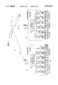
- FIG. 1 is a partial block diagram of a decoder portion according to the present invention
- FIG. 2 is a block diagram showing the video processor of the present invention
- FIG. 3 is a block diagram showing the video interface of the present invention.
- FIG. 4 is an exemplary block diagram showing the VBI data generator of the present invention.
- FIG. 5 is a schematic diagram showing a simple combiner exemplary of the present invention.
- FIG. 6 is a partial block diagram of a system for multiplexing a plurality of digital services for transmission to a plurality of remote locations, as described in U.S. Patent application Ser. No. 968,846;
- FIG. 7 is a graphical illustration of the multiplex data stream generated by an encoder
- FIG. 8 shows in detail the general arrangement and contents of a related an frame of the multiplex data stream for transmitting NTSC video services
- FIG. 9 shows in detail the data and services that can be carried in an exemplary first field of a related art frame of the multiplex data stream
- FIG. 10 shows in detail the data and services that can be carried in an exemplary second field of a related art frame of the multiplex data stream
- FIG. 11 is a block diagram illustrating, in a simplistic manner, an exemplary environment for the present invention.
- FIG. 12 is a block diagram of a decoder 216
- FIG. 13 depicts an exemplary line 21 waveform in accordance with the present invention.
- FIG. 14 is a block diagram of the line 21 former circuit 242 of FIG. 12;
- FIG. 15 is an alternative frame format according to the present invention.
- FIG. 16 is another alternative frame format according to the present invention.
- FIG. 6 shows a partial block diagram of a system 100 for multiplexing a plurality of digital services for transmission to a plurality of remote locations (not shown).
- the system 100 comprises a plurality of service encoders 112 each of which is operated by a "programmer.”
- any number N of programmers may be present in the system 100.
- programmers are entities that provide "programs" for distribution to various subscribers.
- programmer 1 may provide programs 1 through N.
- Each program comprises a set of related services, such as video, audio and closed-captioning services.
- FIG. 6 shows that programmer 1 is providing program 1 which comprises a video service 114 and two related audio services 116, 118 such as stereo sound.
- a given program can comprise a collection of related services, and a programmer may provide any number of programs.
- each encoder 112 has a plurality of analog-to-digital converters 120 for converting services in analog form to digital services.
- video and audio services may be compressed by video and audio compression devices 122, however, compression is not required.
- MPEG Moving Picture Expert Group
- Video quantization is another, more recent compression technique for digital video.
- any compression algorithm may be employed by the video and audio compression devices 122, and the devices 122 are by no means limited to any one compression method.
- compression of audio and video services is not required. Compression merely serves to increase the amount of data that can be transmitted within a given bandwidth.
- Each encoder further comprises a service multiplexer 124.
- the service multiplexers 124 functions in accordance with the method of the present invention to multiplex the individual digital services for transmission to remote locations, such as a cable head-end installation or DBS subscriber.
- the service multiplexer 124 in each encoder 112 generates a multiplex data stream 126 which is fed to a transmitter 128 for transmission to the remote locations via a satellite 130.
- each programmer e.g., programmer 1 . . . programmer N
- the multiplex data streams may be received at various remote locations, such as a cable head-end, a DBS subscriber or a cable subscriber.
- Each remote location employs a service demultiplexer which extracts selected services from the multiplex stream in accordance with the method of the present invention. Further details of the service demultiplexer will be provided hereinafter.
- FIG. 7 is a graphical illustration of the multiplex data stream 126 generated by each service multiplexer 124 in each encoder 112.
- the multiplex data stream 126 comprises a continuous sequence of "frames.”
- Each frame includes two “fields” as shown.
- each field contains multiplexed service data and a "transport layer” that contains certain "system data” necessary for operating the system of the present invention.
- system data are too numerous to transmit in a single field, these types of data are transmitted over a series of fields referred to herein as "Groups of Fields.”
- a group cycle may comprise eight (8) fields; however, a group cycle can be defined by any number of fields.
- group cycles define boundaries in the multiplex data stream 126 within which a complete set of system and encryption related data is transmitted. These group cycle boundaries may be either fixed or dynamically varying. As described hereinafter, the service demultiplexer at each remote location needs the system data in a given group cycle in order to extract selected services from the service data contained in the next group cycle.
- the video services carried in a multiplex data stream typically originate as analog video signals (except for HDTV signals), and as shown in FIG. 6, the analog video signals are "digitized" by analog-to-digital converters 120 and thus become “digital services.”
- selected digital video services are extracted from the multiplex data stream for viewing on a display device, such as a television, for example. Prior to viewing, however, the digital video services must be converted back to their analog form.
- a display device such as a television, for example.
- the digital video services Prior to viewing, however, the digital video services must be converted back to their analog form.
- analog video signal formats widely used in the television industries.
- the NTSC format is widely used in the U.S.
- the PAL format is used in most of Europe.
- the overall frame structure and transmission rate of the multiplex data stream 126 are preferably related to, and dependant upon, the particular analog video format of the video services being carried in the multiplex.
- the frame structure and digital transmission rate of the multiplex differ depending upon whether the video services carried in the multiplex are PAL video signals or NTSC video signals.
- Providing digital multiplex data rates and clocks that are related to key analog video frequencies simplifies hardware design throughout the system. In particular, the regeneration of analog video (as well as audio) signals at subscriber locations is greatly simplified.
- FIG. 8 shows the general arrangement and contents of an exemplary frame of the multiplex data stream of FIG. 7 when the video services carded in the multiplex are based on the NTSC video signal format.
- the frame structure and transmission rate of the multiplex data stream are preferably related to their analog NTSC counterparts.
- F h analog television line frequency
- a frame preferably comprises a plurality of lines each of which are 171 bytes long (i.e., 1368 bits), wherein when the video services carried are NTSC format signals, the frame has 525 lines.
- a digital service may include frames of 525 lines, each line having 171 bytes and transmitted at a rate of 15,734 lines per second to correspond to a respective analog service.
- the 525 lines of the frame correspond to the number of lines in an analog NTSC picture.
- the lines in each frame may be organized to include two "fields," each of which contains 262 lines. A test line 140 is added to the second field to achieve the 525 line total.
- this two-field structure is analogous to the two-field format of NTSC signals.
- each line of the frame is transmitted at a frequency equal to F h , the horizontal line frequency.
- F h is 15.734 kHz.
- the multiplex data rate is: ##EQU1##
- the overall frame rate is 29.97 Hz which is equal to the analog frame rate of NTSC video signals.
- the multiplex rate of 1368 F h does not exactly match the NTSC regeneration rate.
- the NTSC regeneration rate is actually 1365 F h , and therefore, decoders at subscriber locations must perform a rate conversion in order to accurately regenerate the analog NTSC video signals.
- a single 21.5 Mbps multiplex data stream may be modulated and transmitted within a 6 Mhz cable channel, and two 21.5 Mbps multiplex data streams can be interleaved and transmitted over a single C-Band satellite transponder.
- each field of the frame begins with a VSYNC word 142, and each line begins with an HSYNC byte 146.
- a service demultiplexer in a decoder at each subscriber location uses the HSYNC and VSYNC patterns to establish frame and field synchronization after receiving a multiplex data stream.
- the VSYNC word 142 is generated similarly for each field, and may be bit-inverted every other field.
- the HSYNC byte 146 is preferably the same for each line.
- the VSYNC word 142 in each field is preferably followed by a "transport layer" 144.
- the transport layer 144 in each field contains "system data” needed for operation of the system of the present invention, and more importantly, specifies the contents and structure of the "system data” and service data that follow in the field.
- system data needed for operation of the system of the present invention
- service data that follow in the field.
- an important part of the transport layer 144 is the "multiplex map" which follows directly after the VSYNC word 142 in each field.
- the multiplex map specifies the number and location of transport layer packets that follow in the field and is dynamically adjustable on a per field basis to achieve great flexibility.
- the transport layer 1.44 of each field is followed by a service data space 148 which contains the audio and video service data carded in the multiplex data stream.
- the data rate for a service can vary from the HDTV rate (approx. 17 Mbps) to the telecommunications standard T1 data rate of 1.544 Mbps.
- the amount of data assigned to video, audio and other services can be adjusted among the services.
- Portions of the service data space not used for audio services may be reassigned as video or other service data. Audio services are not tied to video services within the field, and therefore, the system can provide "radio" services.
- the individual video services are not required to have the same data rate.
- the possible combinations of services that a programmer can provide in one multiplex data stream are limited only by the maximum data rate of the multiplex data stream (i.e., 21.5 Mbps) and the variable partitioning increment size.
- the transport layer 144 and service data portion 148 of each frame are error coded using a 20 byte Reed-Solomon error correcting code 150.
- FIG. 9 shows further details of the general arrangement and contents of the first field of an exemplary frame of a multiplex data stream in accordance with an embodiment of the present invention.
- the first line of the transport layer 144 i.e., line 2 of the field
- the transport layer may comprise service seed packets 164 (SSP), video multiplex control packets 166 (VMCP), virtual channel map packets 168 (VCM), teletext data packets 170 (TT), addressable data packets 172 (ADP), and optional system packets 174 (OSP).
- SSP service seed packets 164
- VMCP video multiplex control packets 166
- VCM virtual channel map packets 168
- TT teletext data packets 170
- ADP addressable data packets 172
- OSP optional system packets 174
- the multiplex map 162 is transmitted with each field and specifies the number and location of every other type of data packet in the transport layer 144 of that field.
- the number and location of each other type of transport layer packet may be dynamically altered on a per field basis to achieve a great degree of flexibility.
- the multiplex map 162 can be used in a "full-field" mode to allow an entire field of the multiplex data stream to be used for system data such as addressable data packets 174 (ADPs).
- ADPs addressable data packets 174
- not every type of transport layer packet need be transmitted in every field.
- some packets, such as system seed packets 164 (SSPs) may be transmitted only in the first few fields of a cryptocycle. The content and arrangement of data within each packet will be described hereinafter in greater detail.
- each field is allocated to service dam 148.
- audio services, utility data and closed-captioning services and video services are separated within the field.
- utility and closed-captioning data 176 may be transmitted at the beginning of each line of the transport layer 144 as well.
- the audio portion 178 of each field is proportionally allocated among the various audio services being transmitted.
- the size of the audio portion 178 of each field is adjustable for accommodating different numbers of audio services.
- the audio portion 178 of each field may include a maximum of 21 bytes on each line of the service data area 148.
- the video portion 180 of the service data area 148 of each frame comprises a plurality of smaller video data packets 182 (VDPs).
- VDPs may each be 60 bits wide, although any size VDP may be used without deviating from the spirit and scope of the invention.
- Each of the 60 bits in an VDP may be allocated to a particular video service being transmitted. For example, if there are 5 video services being transmitted, each service could be allocated 12 bits out of every VDP.
- the 60 bits in each VDP may be allocated among the various services in proportion to the individual data rate of each service. For example, a video service having a high rate may be allocated more bits in each VDP than a video service having a lower rate.
- VDP video multiplex control packets
- the allocation of services within each VDP may be dynamically altered on a per frame basis only so as to support statistical multiplexing.
- the allocation of services within each VDP may be dynamically altered on a per field basis, if desired.
- FIG. 10 shows details of a second field of an exemplary frame, the embodiment for which FIG. 9 shows the first field, of a multiplex data stream.
- the second field is generally similar in structure and arrangement to the first field; the main difference being the addition of a test line 140.
- the test line 140 is the last line of every frame of the multiplex data stream and allows each field to be exactly 261 lines (not including VSYNC).
- the test line 140 is not error coded with the Reed-Solomon code as are lines 264-524 of the second field.
- the test line may be used to carry system test data, if desired.
- the third and fourth bytes on each line of each field carry utility and closed-captioning data. Only the first 15 of 16 bits are utilized for utility data; the 16th bit is used for closed-captioning data. Additionally, five lines in each frame (i.e., both fields) do not carry utility and closed-captioning data. These include the two VSYNC lines 142, the test line 140 and lines 2 and 264 of the first and second fields respectively. The total bit capacity for utility data for one frame is then:
- the resultant maximum data rate for each channel of utility data is then: ##EQU2## This rate is slightly higher than the industry standard 19.2 KBps rate, but with the excess capacity, worst-case incoming data channels can be handled by running at the slightly higher rate.
- a 19.48 kHz clock is easily derived from F h since 19.48 kHz is equal to 2730/2205 F h .
- the utility data in each frame can be partitioned into 16 separate channels, where each channel runs at 9600 Kbps.
- Closed-captioning data may be transmitted by the last bit of the fourth byte of each line (i.e., bit 16 of the utility & closed-captioning data space).
- closed-captioning data i.e., 1 bit per line
- video services often have associated closed-captioning data.
- two bytes (i.e., two characters) of closed-captioning data are sent on line 21 of each analog video frame.
- the 520 closed-captioning bits are partitioned into 20 separate "channels" of 26 bits each. Each "channel" corresponds to a different video service in the multiplex data stream.
- each frame therefore, up to 20 video services may carry associated closed captioning data.
- the first 26 bits in the frame correspond to video number 1
- the second 26 bits correspond to video number 2, and so on.
- only the first sixteen bits of each 26 bit partition are used.
- line 21 in the analog NTSC format two characters are transmitted per frame per video service.
- the frame within which data is transmitted may be generally in a form of a frame of data demarked by a frame sync and having data internal to the frame separated into one or more segments, each segment demarked by a horizontal sync.
- these terms may have originated in the context of television pictures, there is no reason to be so constrained in the present context of digital transmission in a multiplexed data stream.
- the quantity of data transmitted in association with each frame sync or horizontal sync may differ from the quantity of data transmitted in association with each frame sync or horizontal sync may differ from the quantity of data transmitted in a conventional television picture.
- each frame of data may be organized more in terms of transmission requirements (e.g. transmission through noise in the transmission channel, error correction, different data having different error probability requirements, etc.) than in terms of resolution and update rate of any picture display.
- information transmission may be functionally organized into, for example, low speed data, medium speed data and high speed data as depicted in FIG. 15 as packets, audio data and video data, respectfully.
- the data in the frame depicted in FIG. 15 is preferably apportioned among packets, audio data and video data in such a way as to be indifferent to boundaries between segments demarked by horizontal syncs.
- the data in each segment demarked by a horizontal sync preferably contains an Reed-Solomon (or equivalent) error detection/correction code, the remaining portion of the data segment including functionally partitioned information to be transmitted.
- FIG. 16 shows that the functionally partitioned packet data may be further partitioned into regions 1 and 2, region 1 to be used to transmit information requiring low transmission error probabilities when compared to transmission error probabilities of information contained in region 2.
- region 1 may be used to transmit information requiring low transmission error probabilities when compared to transmission error probabilities of information contained in region 2.
- multiplex structure control or encryption seed delivery may require extra low transmission error probabilities.
- the particular information types to be included in this region 1 may dynamically vary depending on the expected noise level in the physical transmission channel so that the information therein transmitted may be received with a specified low transmission error probability.
- FIG. 11 is a block diagram schematically illustrating uplink encoder 200 and decoder 216 in an environment for an embodiment of the present invention. This figure has been simplified to place the present invention in context.
- Analog NTSC video or PAL
- CC closed-captioning
- All the analog data is converted to digital data and eventually finds its way into the 21.5 Mbps multiplex.
- the multiplexed data is fed to a transport ASIC 218 in a decoder 216 (i.e., after passing through the uplink and downlink channels), which decoder demultiplexes the data and provides the CC, TEXT and Video data separately to a video board 220 that digitally recreates the original line 21 and converts it to analog form.
- the video board also decodes the MPEG encoded video, converters it to analog and inserts line 21 in the appropriate line and field, thereby reproducing the original NTSC video signal.
- the system is also capable of reconstructing PAL video signals.
- FIG. 12 shows details of the video board of FIG. 11.
- teletext data in digital RGB form is received and fed to an RGB-to-YUV converter 234 and then passed to a multiplexer 246.
- MPEG encoded video is received at the 21.5 Mbps rate and fed to a rate converter/protocol manager 230. From there the encoded video is decoded using an MPEG Video Decoder Chip 232, which is available from C-Cube Microsystems (part no. CL950).
- the MPEG Chip is capable of decoding both NTSC and PAL video, depending on the microcode it receives from a memory 236 via a switch 238. The decoded video is then sent to the other input of the multiplexer 246.
- NTSC decoded NTSC
- PAL decoded NTSC
- the D/A converter is capable of producing either NTSC or PAL analog signals from digital inputs.
- the microprocessor 240 tells both the MPEG decoder and the analog video encoder which signal to produce.
- the multiplexer is described in detail in the above-referenced U.S. patent application Ser. No. 968,846.
- Closed-captioning data may be fed to the decoder 216 at a rate of 26 bits per frame.
- the 26 bits of CC data are passed to a line 21 former circuit 242, which regenerates line 21 in analog form.
- the line 21 former circuit and an associated timing generator circuit 244 are described below with reference to FIG. 13.
- line 21 is inserted into the proper NTSC analog video field by a second multiplexer 250.
- the circuit is controlled by a microprocessor 240.
- FIG. 13 illustrates the line 21 wave form according to one embodiment of this invention.
- the signal begins with a start bit.
- the start bit is followed by a sine wave (RUN IN) which is used to alert a CC decoder and establish synchronization.
- the sine wave is followed by two characters of closed captioning text (CHAR 1 and 2).
- a stop bit follows. When a subscriber buys a closed captioning decoder, that decoder simply pulls line 21 out of every NTSC frame, buffers the CC text characters until full sentences have been received, and then displays them on the screen for the user to read. This process is described below.
- FIG. 14 depicts details of the line 21 former circuit 242 of FIG. 12.
- the 26 bits of CC data provided in each frame are received by a data stripper and storage unit 260 that buffers the received data and separates every two characters (i.e., bytes) of CC data.
- the two characters to be inserted in a given line 21 are then stored in a 16-bit register 262.
- the register is clocked with a frame sync signal so that the characters are provided on a frame boundary (recall that line 21 is provided every other field, i.e., once per frame).
- the two characters are then sent to a circuit 264 that inserts the start bit and required dead time into the signal.
- the CC information is still digital at this point. This is then fed to multiplexer 270.
- a digital sine wave generator 268 creates a digital sine wave which is supplied to the other input of the multiplexer 270.
- the line 21 enable line goes high for the entire line 21 interval.
- the line 21 interval former controls the multiplexer 270, the sine wave generator 268, and the start bit and dead-time insert circuit 264 so that a complete digital representation is converted to analog in a D/A summing network 272.
- the analog signal is then low-pass filtered by a filter 274 to remove sharp edges.
- the result is an analog reconstruction of the original line 21 that was separated from the NTSC video at the encoder 112.
- the reconstructed line 21 is then inserted into the appropriate analog NTSC field.
- line 21 is completely reconstructed digitally. Specifically, the sine wave is reconstructed digitally, and then the entire digital representation is D/A converted. Another option would be to generate the sine wave in analog. However, by constructing the sine wave digitally, the entire line 21 former circuit can be implemented in a single ASIC. Thus, a mix of discrete analog and digital circuitry is not required.
- FIG. 1 is a block diagram showing a portion 10 of a decoder for such digital multiplexed data services.
- This portion 10 includes the multiplexer 12 controlled by microcontrol 14 under direction of front panel controls 16 actuated by a user.
- the demultiplexed data stream may include text information or audio information, for example, stereo music distribution. This text information and audio information is reconstructed in text processor 18 and audio processor 20, respectively.
- the demultiplexed information may also include video information with associated ancillary data information (e.g., sound associated with the video information). This information is processed in video processor 30.
- video processor 30 includes video process decompressor 32, compression control processor 34 and video interface 40.
- the compressed video data input to video process decompressor 32 includes blocks of data such as compressed video, associated audio, other overhead control information and user data.
- the video process decompressor 32 reduces decompressed video data which is output to video interface 40.
- the video process decompressor 32 also separates out the user data which is output to compression control processor 34.
- the compression control processor 34 identifies and culls out vertical blanking interval data which has been packed into the user data.
- the VBI is then output from the compression control processor 34 to the video interface 40.
- text (TTX) dam from text processor 18 or from video process decompressor 32 or other source is also provided to video interface 40.
- Video interface 40 processes these signals to output composite video signal data.
- video interface 40 includes demultiplexer 44 for receiving the decompressed video data from the video process decompressor and separating the data into brightness Y data and color UV data to be fed to interpolators 46, 48, respectively.
- Video interface 40 includes Y interpolator 46 and UV interpolator 48 for producing interpolated Y and interpolated UV data which is output to multiplex mixer 50.
- the video interface also includes VBI data generator 60 which receives the VBI data from compression control processor 34 and generates a VBI signal data which is output to the multiplex mixer 50.
- video interface 40 also includes converter 58 for converting RGB text information into YUV text information.
- the video interface 40 includes an interface control 42 receiving horizontal and vertical synchronization information and input data from the compression control processor and producing output data to the compression control processor and a variety of control signals to control the operation of circuits associated with video interface 40, for example, controlling interpolators 46 and 48, or for example, controlling multiplex mixer 50.
- the video interface 40 serves as a video post processor to the video process decompressor, for example, a standard video decompressor based on, for example, MPEG (Moving Picture Expert Group) video standards.
- Interface circuit 40 receives decompressed video data from the MPEG video decompressor, as a sequence of digitally represented data samples, and outputs composite signal data, also as a sequence of digitally represented data samples, corresponding to standard composite video signals such as NTSC signals or PAL signals.
- Video interface 40 preferably processes 16-bit YUV data with a 4:2:2 sampling rate as defined by a CCIR 601 standard.
- Interpolator 46, 48 are preferably designed to support all standard resolutions, for example, 352, 480, 544 and 720 horizontal resolution cells per line.
- interpolators 46 performs 1:2, 2:3 and 3:4 interpolation on brightness Y data, and UV interpolator performs 1:4, 2:6 and 3:8 interpolation on color data U and color data V.
- Interface control 42 controls the interpolator multiplexers for passing data in a format which supports all standard frame dimensions, for example, 525 lines per frame and 625 lines per frame.
- multiplex mixer 50 mixes (by multiplexing) interpolated Y data, as a sequence of digitally represented data samples, and interpolated UV data, also as a sequence of digitally represented data samples, from interpolators 46 and 48, respectively, with VBI signal data, also as a sequence of digitally represented data samples, from VBI data generator 60 to output brightness data Y and color difference data U and V as sequences of digitally represented data samples in a frame-based format which includes lines for 10 carrying the VBI signal data.
- line 21 may be included to carry closed captioning data.
- Interface control 42 controls the beginning reference of the sampled data sequences so as to correspond with the active video portion of, for example, an NTSC type signal.
- Color difference data U is provided to a first input of U multiplier 56 and color difference data V is provided to a first input of V multiplier 54.
- Video interface 40 also includes subcarrier generator 52 controlled by interface control 42 to generate a cosine wave form and a sine wave form corresponding to a predetermined color subcarrier wave form and at a phase and frequency of the subcarrier wave.
- the sine wave form is supplied to a second input of U multiplier 56 as a sequence of digitally represented data samples and the cosine wave form is supplied to a second input of V multiplier 54 also as a sequence digitally represented data samples.
- the video interface 40 also includes a final multiplexer 70 to select between either color difference data UV (to output data in a format such as CCIR 601) or the output of U multiplier 56 and V multiplier 54 to output sampled data sequences corresponding to the chroma signal in NTSC composite video, as controlled by interface control 42.
- multiplexer 70 provides at its output color video data having encoded therein either color different signal data UV or chroma signal data C.
- the interface control 42 also produces composite synchronization signals as a sequence of digitally represented data samples.
- control interface 42 controls the timing of the generation of brightness Y data (also referred to as luminance data) and either color difference data UV or chroma data C (i.e., UV data modulated on the cosine and sine wave forms from subcarrier generator 52).
- the timing of the generation of this data is controlled with respect for the HV synchronization input to control interface 42 so as to coincide with the active video portion of a standard line of composite video data.
- control interface 42 controls the timing of the generation of the VBI signal data to coincide with the same active video portion.
- Control interface 42 controls multiplex mixer 50 to selectively switch the VBI signal data (as a sampled data sequence) into the brightness Y and/or color differences UV output of multiplex mixer 50 (also a sampled data sequence). Any particular scan line may be output from the video interface, for example, a sampled data sequence produced in VBI data generator 60 containing closed captioning data may be switched into the brightness Y output of multiplex mixer 50 during the active video portion of scan line 21.
- the composite synchronization data, output from interface control 42 is a digitally represented sampled data sequence whose timing with respect to the HV synchronization input to control interface 42 is controlled to complement the brightness Y data output from multiplex mixer 50 so that when combined, the combined digitally represented sampled data sequence will correspond to a standard composite video signal, for example, as defined by EIA RS-170A, thus achieving a digitally represented sampled data sequence corresponding to, for example, a black and white NTSC video signal.
- interface control 42 controls subcarrier generator 52, the U and V outputs of multiplex mixer 50, and final multiplexer 70 to generate chroma data C in order to add color to the black and white NTSC data sequence described above.
- the timing and IRE levels of the subcarrier generation are controlled to generate the correct phase angle and amplitude for both the chroma burst portion of a color NTSC composite video signal and the color subcarrier wave onto which UV signal data are modulated.
- the timing of the U and V sampled data sequences output from multiplex mixer 50 and a cosine and sine color subcarrier wave form sampled data sequence is controlled to coincide with the active video portion of the composite video data described above so that the output of multipliers 54, 56 correspond to a modulated chroma signal having color difference signals U and V modulated on the color subcarrier wave form.
- multiplex mixer 50 can be controlled by interface control 42, in accordance with parameters (e.g. A and B, each of which may be either positive or negative quantities) received from the compression control processor (e.g. through input port CCP IN), to output predetermined constants as outputs U and V during the chroma burst portion of the composite video data so that a precise phase controlled angle and amplitude color subcarrier wave is provided at the output of final mixer 70 during the chroma burst portion, the phase and amplitude color subcarrier wave being
- the amplitude of the U and V signal data may be set to zero to eliminate color and produce a black and white picture.
- multiplexer 70 may be designed to include an adder at its C output to add a constant (e.g. K) to its C output and that interface control 42 may control the DC offset of the C output in accordance with a parameter (e.g. K) received from the compression control processor, the offset C output being
- FIG. 5 shows an example of an exemplary combiner 80 to combine the sample data sequences of brightness Y, chroma C and composite sync data.
- a sampled data sequence is controlled, in multiplex mixer 50, final multiplexer 70 or interface control 42 to be zero whenever the sampled data sequence is not to be added in the combiner.
- the sampled data sequences may be multiplexed together (for example, with tri-state outputs from 50, 70 and 42) and only one digital to analog converter is used.
- Subcarrier generator 52 enables the video interface 40 to generate the necessary modulation for color NTSC signals and PAL signals.
- the control interface 42 is able to generate the necessary composite synchronization signals for NTSC and PAL signals.
- VBI data generator 60, multiplex mixer 50 and multiplexer 70 enable VBI data which had been previously encoded in the user data sent over the compressed video data to be regenerated and reinserted into the composite video data.
- a full 720 resolution samples per line is preferred in the composite video data.
- intermediate values are interpolated in interpolators 46, 48 to generate 720 resolution samples in accordance with Table 1.
- each of the U and V data is sampled at half the rate of the Y data. Therefore, the number of samples to be interpolated is twice that of the luminance (or brightness data).
- the interpolator is preferably a 7-tap finite impulse response filter.
- Interface control 42 also has an input port CCP IN to receive processing commands (e.g. color burst phase, amplitude and DC offset parameters) from the compression control processor and an output port CCP OUT to send timing (e.g. line and field numbers) and status signals to the compression control processor or other circuits requiring timing signals such as line number or field number being processed.
- Input port CCP IN may, for example, include three terminals: data strobe, data in, and enable data.
- VBI data generator 60 includes filter 62 and scaling circuitry 64.
- the VBI data generator is a general purpose two-level signal generator.
- the VBI data is sent to the decoder via an MPEG user data stream.
- the compression control processor pulls the data from the MPEG decompressor and passes the VBI data to video interface 40.
- the video interface 40 receives the VBI data from the compression control processor at control interface 42 and regenerates the VBI signal data as a sequence of digitally represented data samples in VBI data generator 60.
- the VBI signal data is preferably regenerated by filtering a one-bit data stream through a filter (for example, a finite impulse response filter) at 27 MHz clock rate.
- a filter for example, a finite impulse response filter
- the output of the filter is preferably a data stream with an eight-bit output and a rise and fall time of approximately 500 nanoseconds. Scaling can then be done on the eight-bit data stream to scale the signal to the proper IRE levels in accordance with high level and low level parameters received at control interface 42 from the compressor control processor.
- the filter is preferably an 11-tap finite impulse response filter, one bit in and eight bits out, with coefficients: 1, 4, 8, 12, 15, 16, 15, 12, 8, 4 and 1, which provide a rise time of approximately 500 nanoseconds.
- Standard MPEG decompressors decompress compressed video data and produce decompressed video data and system user data.
- the system user data may be associated with any layer of the MPEG format, referred to as a layer of the MPEG grammar: video sequence layer, groups of pictures layer, picture layer and slice layer.
- the MPEG decompressor tags the user data with a code to indicate the layer with which the user data is associated.
- VBI data is encoded in user data associated with the picture layer.
- the decompression control processor scans through all user data received to cull out those user data packets associated with the picture layer and then further scans the user data associated with picture layers to cull out those user data packets identified as containing VBI data, for example, closed captioning data, although any form of data may be transferred in this way.
- VBI data for example, closed captioning data
- the user data may contain phase, amplitude and DC offset parameters of the color subcarrier associated with a particular picture. This is especially useful when the color subcarrier in the particular video data stream is unusual or abnormal in that its color subcarrier is characterized by an unexpected phase, amplitude or DC offset.
- Standard MPEG decompressors also decompress compressed audio data.
- a television-type data stream will contain both video and audio data streams.
- the VBI data for example, line 21 closed captioning data
- An English language television type data stream being transported into a French-speaking household having a deaf family member may preferably have both a French language audio data stream and associated therewith a French language line 21 closed captioning data stream.
- an English language television-type data stream being broadcast into a dual language speaking area may preferably have an English language audio data stream with French subtitles being broadcast in the line 21 closed captioning data stream, or vice versa. This might also prove to be a popular way to teach a foreign language.
- the VBI data is preferably transmitted in a 256 bit user data packet associated with the video data stream (picture level) of an industry standard format such as the MPEG standard.
- the VBI data can be transmitted in either the video data stream or the associated audio data stream.
- the compression control processor reads the VBI data from the video process decompressor and passes the VBI data to the video interface.
- the data includes VBI header data, for example, in accordance with Table 2. Skilled persons will appreciate that phase, amplitude and DC offset parameters for the color subcarrier wave form, as discussed above, may also be encoded in the VBI header data in order to precisely control generation of color wave forms as discussed above.
- the present invention provides for the bit rate by defining the symbol width (e.g., bit width for closed captioning data) in terms of 27 MHz clock counts; provides for IRE level of the high bit level and low bit level in terms data high and low values and defines the scanning line number in terms of line and field number.
- symbol width e.g., bit width for closed captioning data
- line 21 closed captioning data includes a RUN IN sine wave and 16 bits of data (16 symbols designated A-P) usually organized into two 7-bit bytes plus one parity bit per byte.
- the number of bits or equivalent for RUN IN in a line 21 signal needs to be 32, or the data rate needs to be 32 times the horizontal line scan rate fH (i.e., 32 fH).
- To generate a signal having a symbol data rate of 32 fH requires a symbol transfer and sampling rate of 64 fH due to Nyquist's sampling theorem.
- the number of samples per line may be 858 fH (at 13.5 MHz samples) or 1716 fH (at 27 MHz samples).
- the width of the closed captioning data symbols (e.g., sample bits) which may be regenerated in line 21 is 1716 samples per line divided by 64 samples per line or about 27 samples per symbol, the symbol width.
- the VBI data packet for closed captioning data should have its header set so that line 21 is specified, symbol width should be specified at 27, 27 MHz clocks, the number of symbols at 64. Appropriate high and low data levels are also specified.
- the 64 symbols to generate the RUN IN and bits A-P are: ##STR1##
- VBI data may be stripped off analog signals at the encoder end and reconstructed at the decoder end including such data as SMPTE time code on line 15 and Nielson station identification code on line 20 or 22.
- Some of the data to be sent may be repetitive wide bandwidth data which cannot be completely sent in the active video portion of a single scanning line.
- the VITS signal may be undersampled (e.g., every Nth Nyquist sample) at the encoder end and in the user data packet associated with the first picture frame. Then, the VITS signal is again undersampled (every Nth Nyquist sample) but time shifted by one sample, then encoded in a user data packet associated with second picture frame. This process is again repeated for the third through Nth picture frames until a fully sampled VITS signal is transferred.
- each user data packet is decoded and saved until all picture frames are received and the undersampled data from the user data packets associated with all picture frames is combined to reconstruct the VITS signal.
- the MPEG standard formats can be used to transfer the repetitive wide bandwidth VBI signals in the original signal provided by a programmer service.
- closed captioning data is separated from the analog NTSC video signal provided by a video service programmer and encoded into the last bit of the fourth byte of the bits that constitute a line in the digital frame format which is therein disclosed.
- the digital frames of data are transmitted from encoder to decoder.
- a demultiplexer separates the closed captioning data from video data, and a video board regenerates the closed captioned data as an analog signal, converts the video data into an analog signal, and inserts the regenerated analog closed captioning signal in line 21 of the analog video signal.
- the closed captioning data is encoded in user data defined by MPEG standards or equivalent, in contrast to being encoded into the data of a video frame as disclosed in U.S. Patent application Ser. No. 08/006,476. Circuits are provided by industrial sources to decompress and associate the video, audio and user data according to industry-wide MPEG standards.
- a compression control processor is controlled to cull the closed captioning data out of the MPEG user data and output the closed captioning data to the video interface of the present invention.
- VBI data may be substituted for the closed captioning data and will hereafter be referred to as VBI data.
- the user data packet has encoded therein a Pan-scan code.
- a 16:9 aspect ratio formatted picture may be transmitted; however, when the decoder produces video signals for a 4:3 aspect ratio format display device or television only a center portion of the 16:9 aspect ratio formatted picture may be displayed.
- the Pan-scan code defines the offset from which the 4:3 aspect ratio formatted picture is to be extracted.
- the Pan-scan offset code is preferably encoded in the user data packet associated with the picture layer of the video data.
- the MPEG1 decompressor provides the user data to the compression control processor and the compression control processor decodes the user data and provides the Pan-scan offset codes to control interface 42 of video interface 40.
- the video interface 40 is preferably manufactured as a single integrated circuit.
Abstract
Description
(525-5)lines*(15 bits/line)=7800 bits.
975*2/3=650 bits/channel/frame.
A*cos(ωt)+B*sin(ωt).
A*cos(ωt)+B*sin(ωt)+K.
              TABLE 1
______________________________________
Input Resolution
              Y Interpolation
                          UV Interpolation
______________________________________
352           1:2         1:4
480           2:3         2:6
544           3:4         3:8
______________________________________
TABLE 2 ______________________________________ Data Field Field Size______________________________________ Packet ID 8bits Line Numbers 5 bits Field Odd/Even 1 bit Spare 2 bitsData High Value 8 bitsData Low Value 8 bits Symbol Width (27 MHz clock counts) 8 bits# Data Symbols 8 bits Data 0-208 bits ______________________________________
Claims (20)
Priority Applications (17)
| Application Number | Priority Date | Filing Date | Title |
|---|---|---|---|
| US08/160,828 US5493339A (en) | 1993-01-21 | 1993-12-03 | System and method for transmitting a plurality of digital services including compressed imaging services and associated ancillary data services |
| TW83111146A TW318992B (en) | 1993-01-21 | 1994-11-30 | |
| MA23707A MA23380A1 (en) | 1993-12-03 | 1994-12-01 | SYSTEM AND METHOD FOR TRANSMITTING A PLURALITY OF DIGITAL SERVICES INCLUDING COMPRESSED IMAGE SERVIVES AND ASSOCIATED SUBORDINATE DATA SERVICES |
| HU9601499A HUT75274A (en) | 1993-12-03 | 1994-12-02 | Digital video transmitting system |
| CZ961547A CZ154796A3 (en) | 1993-12-03 | 1994-12-02 | Digital system for image transmission |
| BR9408234A BR9408234A (en) | 1993-12-03 | 1994-12-02 | Video interface for processing uncompressed video data and vbi data in composite video data and color controlled data in composite video data and panscan data in composite video data |
| JP51575695A JP3762428B2 (en) | 1993-12-03 | 1994-12-02 | Digital video transmission system |
| CA002177563A CA2177563C (en) | 1993-12-03 | 1994-12-02 | Digital video transmitting system |
| AU13336/95A AU679824B2 (en) | 1993-12-03 | 1994-12-02 | Digital video transmitting system |
| CN94194910A CN1048137C (en) | 1993-12-03 | 1994-12-02 | Digital video transmitting system |
| EP95904786A EP0732033A4 (en) | 1993-12-03 | 1994-12-02 | Digital video transmitting system |
| PCT/US1994/013799 WO1995015660A1 (en) | 1993-12-03 | 1994-12-02 | Digital video transmitting system |
| PL94315201A PL175544B1 (en) | 1993-12-03 | 1994-12-02 | Method of transmitting a digital video signal |
| KR1019960702922A KR100330819B1 (en) | 1993-12-03 | 1994-12-02 | Digital video transmission system |
| DE0732033T DE732033T1 (en) | 1993-12-03 | 1994-12-02 | DIGITAL VIDEO TRANSMISSION SYSTEM |
| TW83111443A TW261703B (en) | 1993-12-03 | 1994-12-08 | |
| JP2004033519A JP2004222308A (en) | 1993-12-03 | 2004-02-10 | Digital video transmission system |
Applications Claiming Priority (2)
| Application Number | Priority Date | Filing Date | Title |
|---|---|---|---|
| US647693A | 1993-01-20 | 1993-01-20 | |
| US08/160,828 US5493339A (en) | 1993-01-21 | 1993-12-03 | System and method for transmitting a plurality of digital services including compressed imaging services and associated ancillary data services |
Related Parent Applications (1)
| Application Number | Title | Priority Date | Filing Date |
|---|---|---|---|
| US647693A Continuation-In-Part | 1993-01-20 | 1993-01-20 |
Publications (1)
| Publication Number | Publication Date |
|---|---|
| US5493339A true US5493339A (en) | 1996-02-20 |
Family
ID=22578631
Family Applications (1)
| Application Number | Title | Priority Date | Filing Date |
|---|---|---|---|
| US08/160,828 Expired - Lifetime US5493339A (en) | 1993-01-21 | 1993-12-03 | System and method for transmitting a plurality of digital services including compressed imaging services and associated ancillary data services |
Country Status (14)
| Country | Link |
|---|---|
| US (1) | US5493339A (en) |
| EP (1) | EP0732033A4 (en) |
| JP (2) | JP3762428B2 (en) |
| KR (1) | KR100330819B1 (en) |
| CN (1) | CN1048137C (en) |
| AU (1) | AU679824B2 (en) |
| BR (1) | BR9408234A (en) |
| CA (1) | CA2177563C (en) |
| CZ (1) | CZ154796A3 (en) |
| DE (1) | DE732033T1 (en) |
| HU (1) | HUT75274A (en) |
| MA (1) | MA23380A1 (en) |
| PL (1) | PL175544B1 (en) |
| WO (1) | WO1995015660A1 (en) |
Cited By (115)
| Publication number | Priority date | Publication date | Assignee | Title |
|---|---|---|---|---|
| WO1997001930A1 (en) * | 1995-06-28 | 1997-01-16 | Nextlevel Systems, Inc. | Bandwidth efficient communication of user data in digital television data stream |
| US5598415A (en) * | 1995-08-04 | 1997-01-28 | General Instrument Corporation Of Delaware | Transmission of high rate isochronous data in MPEG-2 data streams |
| US5619424A (en) * | 1993-10-29 | 1997-04-08 | Time-Warner Entertainment Co., L.P. | Software carrier for storing digital data representative of picture information and including pan scan data |
| US5635657A (en) * | 1994-06-22 | 1997-06-03 | Samsung Electronics Co., Ltd. | Recording medium for video-song accompaniment and video-song accompaniment apparatus adopting the same |
| US5668873A (en) * | 1994-03-27 | 1997-09-16 | Sony Corporation | Video signal processor with copy prevention function |
| US5694334A (en) * | 1994-09-08 | 1997-12-02 | Starguide Digital Networks, Inc. | Method and apparatus for electronic distribution of digital multi-media information |
| US5734432A (en) * | 1994-07-15 | 1998-03-31 | Lucent Technologies, Inc. | Method of incorporating a variable rate auxiliary data stream with a variable rate primary data stream |
| US5739869A (en) * | 1993-09-10 | 1998-04-14 | Figaro, Inc. | Electronic libretto display apparatus and method |
| WO1998015887A2 (en) * | 1996-10-09 | 1998-04-16 | Starguide Digital Networks | Aggregate information production and display system |
| US5745184A (en) * | 1993-08-20 | 1998-04-28 | Thomson Consumer Electronics, Inc. | Closed caption system for use with compressed digital video transmission |
| EP0843478A2 (en) * | 1996-11-12 | 1998-05-20 | NextLevel Systems, Inc. | Dynamic relocation of the service data channel |
| US5757416A (en) * | 1993-12-03 | 1998-05-26 | Scientific-Atlanta, Inc. | System and method for transmitting a plurality of digital services including imaging services |
| US5774676A (en) * | 1995-10-03 | 1998-06-30 | S3, Incorporated | Method and apparatus for decompression of MPEG compressed data in a computer system |
| US5778096A (en) * | 1995-06-12 | 1998-07-07 | S3, Incorporated | Decompression of MPEG compressed data in a computer system |
| EP0854654A2 (en) * | 1997-01-16 | 1998-07-22 | Nextlevel Systems, Inc. | Communication of VBI data in digital television data streams |
| US5801782A (en) * | 1996-03-21 | 1998-09-01 | Samsung Information Systems America | Analog video encoder with metered closed caption data on digital video input interface |
| US5818967A (en) * | 1995-06-12 | 1998-10-06 | S3, Incorporated | Video decoder engine |
| KR19980070568A (en) * | 1997-01-16 | 1998-10-26 | 샤운 엘. 맥클린토크 | Waveform Generator for Inserting Data into Digital Television Signals |
| US5850218A (en) * | 1997-02-19 | 1998-12-15 | Time Warner Entertainment Company L.P. | Inter-active program guide with default selection control |
| AU701138B2 (en) * | 1995-07-13 | 1999-01-21 | General Instrument Corporation | Transmission of high rate isochronous data in MPEG-2 data streams |
| US5907366A (en) * | 1996-04-02 | 1999-05-25 | Digital Video Systems, Inc. | Vertical blanking insertion device |
| US5926613A (en) * | 1996-09-27 | 1999-07-20 | Sony Corporation | Method and apparatus for encoding pan-edit vectors for film to tape transfer |
| US5966120A (en) * | 1995-11-21 | 1999-10-12 | Imedia Corporation | Method and apparatus for combining and distributing data with pre-formatted real-time video |
| US5977962A (en) * | 1996-10-18 | 1999-11-02 | Cablesoft Corporation | Television browsing system with transmitted and received keys and associated information |
| US6005629A (en) * | 1996-05-29 | 1999-12-21 | Sgs-Thomson Microelectronics S.A. | System for converting digital television signals with insertion of interactive menus |
| US6011797A (en) * | 1996-07-17 | 2000-01-04 | Nec Corporation | ATM communication device using interface signal of HIPPI |
| US6018369A (en) * | 1996-03-21 | 2000-01-25 | Samsung Electronics Co., Ltd. | Video decoder with closed caption data on video output |
| US6072532A (en) * | 1997-02-18 | 2000-06-06 | Scientific-Atlanta, Inc. | Method and apparatus for generic insertion of data in vertical blanking intervals |
| US6115074A (en) * | 1997-07-10 | 2000-09-05 | Ozkan; Mehmet Kemal | System for forming and processing program map information suitable for terrestrial, cable or satellite broadcast |
| WO2000052891A1 (en) * | 1999-03-04 | 2000-09-08 | Sarnoff Corporation | Method and apparatus for carrying digital data as analog video |
| US6122660A (en) * | 1999-02-22 | 2000-09-19 | International Business Machines Corporation | Method for distributing digital TV signal and selection of content |
| WO2000060867A1 (en) * | 1999-04-06 | 2000-10-12 | Satellite Advanced Technologies Inc. | Digital video lan system |
| US6188788B1 (en) * | 1997-12-09 | 2001-02-13 | Texas Instruments Incorporated | Automatic color saturation control in video decoder using recursive algorithm |
| US6204885B1 (en) * | 1995-11-13 | 2001-03-20 | Gemstar Development Corp. | Method and apparatus for displaying textual or graphic data on the screen of television receivers |
| US20010000457A1 (en) * | 1995-08-16 | 2001-04-26 | Hinderks Larry W. | Method and apparatus for dynamic allocation of transmission bandwidth resources and for transmission of multiple audio signals with a video signal |
| US6256072B1 (en) * | 1996-05-03 | 2001-07-03 | Samsung Electronics Co., Ltd. | Closed-caption broadcasting and receiving method and apparatus thereof suitable for syllable characters |
| US20010014122A1 (en) * | 1998-09-15 | 2001-08-16 | Fu Hsin Chia | Method and apparatus for video compression and restructuring |
| US6278733B1 (en) | 1996-07-30 | 2001-08-21 | Tiernan Communications, Inc. | System and method for digitally encoding and compressing analog signals carried in the vertical blanking interval of television signal |
| US6282366B1 (en) * | 1994-01-20 | 2001-08-28 | Sony Corporation | Method and apparatus for digitally recording and reproducing data recorded in the vertical blanking period of video signal |
| US20010038686A1 (en) * | 1995-04-10 | 2001-11-08 | Larry Hinderks | Method and apparatus for transmitting coded audio signals through a transmission channel with limited bandwidth |
| US6330036B1 (en) * | 1998-03-24 | 2001-12-11 | Mitsubishi Denki Kabushiki Kaisha | Digital video receiving apparatus |
| US20020035724A1 (en) * | 1994-08-23 | 2002-03-21 | Wise Adrian Philip | Data rate conversion |
| US6378101B1 (en) * | 1999-01-27 | 2002-04-23 | Agere Systems Guardian Corp. | Multiple program decoding for digital audio broadcasting and other applications |
| US6418271B1 (en) * | 1993-10-29 | 2002-07-09 | Time Warner Entertainment Co., L.P. | Data structure for representing video program subtitles |
| US20020105955A1 (en) * | 1999-04-03 | 2002-08-08 | Roberts Roswell R. | Ethernet digital storage (EDS) card and satellite transmission system including faxing capability |
| US6438317B1 (en) * | 1997-09-25 | 2002-08-20 | Sony Corporation | Encoded stream generating apparatus and method, data transmission system and method, and editing system and method |
| US6473903B2 (en) * | 1996-12-30 | 2002-10-29 | Koninklijke Philips Electronics N.V. | Method and system for implementing interactive broadcast programs and commercials |
| US6481012B1 (en) | 1999-10-27 | 2002-11-12 | Diva Systems Corporation | Picture-in-picture and multiple video streams using slice-based encoding |
| US20020177914A1 (en) * | 1995-09-01 | 2002-11-28 | Tim Chase | Audio distribution and production system |
| US20030028879A1 (en) * | 1999-10-27 | 2003-02-06 | Gordon Donald F. | Picture-in-picture and multiple video streams using slice-based encoding |
| US20030110025A1 (en) * | 1991-04-06 | 2003-06-12 | Detlev Wiese | Error concealment in digital transmissions |
| US6584153B1 (en) | 1998-07-23 | 2003-06-24 | Diva Systems Corporation | Data structure and methods for providing an interactive program guide |
| US6614843B1 (en) | 1999-04-15 | 2003-09-02 | Diva Systems Corporation | Stream indexing for delivery of interactive program guide |
| US6621870B1 (en) | 1999-04-15 | 2003-09-16 | Diva Systems Corporation | Method and apparatus for compressing video sequences |
| US6674921B1 (en) * | 1999-09-30 | 2004-01-06 | Umax Data Systems Inc. | Method of image sampling and apparatus thereof |
| EP1383317A1 (en) * | 2002-07-17 | 2004-01-21 | Thomson Licensing S.A. | Video apparatus |
| US20040025178A1 (en) * | 1998-07-23 | 2004-02-05 | Gordon Donald F. | Interactive user interface |
| US20040031048A1 (en) * | 1999-12-03 | 2004-02-12 | Horlander Karl Francis | Adaptive video image information processing system |
| US6704359B1 (en) | 1999-04-15 | 2004-03-09 | Diva Systems Corp. | Efficient encoding algorithms for delivery of server-centric interactive program guide |
| US6710781B1 (en) * | 1999-09-06 | 2004-03-23 | Sony Corporation | Image display apparatus having different display mode and method thereof |
| US20040075668A1 (en) * | 1994-12-14 | 2004-04-22 | Van Der Meer Jan | Subtitling transmission system |
| US6754905B2 (en) | 1998-07-23 | 2004-06-22 | Diva Systems Corporation | Data structure and methods for providing an interactive program guide |
| US6792618B1 (en) | 1998-03-02 | 2004-09-14 | Lucent Technologies Inc. | Viewer customization of displayed programming based on transmitted URLs |
| US20040210931A1 (en) * | 1998-11-30 | 2004-10-21 | Gordon Donald F | Service provider side interactive program guide encoder |
| US20040230391A1 (en) * | 2003-05-15 | 2004-11-18 | Jorgensen Jerry D. | Method, apparatus and system for digital data resampling utilizing fourier series based interpolation |
| US20050034155A1 (en) * | 1999-10-27 | 2005-02-10 | Gordon Donald F. | Apparatus and method for combining realtime and non-realtime encoded content |
| US20050068462A1 (en) * | 2000-08-10 | 2005-03-31 | Harris Helen J. | Process for associating and delivering data with visual media |
| US20050099969A1 (en) * | 1998-04-03 | 2005-05-12 | Roberts Roswell Iii | Satellite receiver/router, system, and method of use |
| US6904610B1 (en) | 1999-04-15 | 2005-06-07 | Sedna Patent Services, Llc | Server-centric customized interactive program guide in an interactive television environment |
| US6934965B2 (en) | 1998-07-23 | 2005-08-23 | Sedna Patent Services, Llc | System for generating, distributing and receiving an interactive user interface |
| US6965593B2 (en) | 1996-11-12 | 2005-11-15 | Ds Systems, Inc. | High bandwidth broadcast system having localized multicast access to broadcast content |
| US6968567B1 (en) | 1999-04-15 | 2005-11-22 | Sedna Patent Services, Llc | Latency reduction in providing interactive program guide |
| US20050270420A1 (en) * | 2004-06-03 | 2005-12-08 | Realtek Semiconductor Corp. | Data receiving apparatus and method of the same |
| US7042949B1 (en) | 2001-04-03 | 2006-05-09 | Rosum Corporation | Robust data transmission using broadcast digital television signals |
| US7058965B1 (en) | 1999-04-15 | 2006-06-06 | Sedna Patent Services, Llc | Multiplexing structures for delivery of interactive program guide |
| US7071995B1 (en) * | 1999-05-28 | 2006-07-04 | Thomson Licensing | Adaptive video image information processing system |
| US7091968B1 (en) | 1998-07-23 | 2006-08-15 | Sedna Patent Services, Llc | Method and apparatus for encoding a user interface |
| US20060184979A1 (en) * | 1999-06-28 | 2006-08-17 | Sedna Patent Services, Llc | System and method for delivery of short-time duration video segments |
| US7127737B1 (en) | 2000-01-26 | 2006-10-24 | Sedna Patent Services, Llc | Bandwidth management techniques for delivery of interactive program guide |
| US20060268300A1 (en) * | 2005-05-27 | 2006-11-30 | Fuji Photo Film Co., Ltd. | Moving picture real-time communications terminal, control method for moving picture real-time communications terminal, and control program for moving picture real-time communications terminal |
| US20070046620A1 (en) * | 2005-08-29 | 2007-03-01 | Fuji Xerox Co., Ltd. | Light transmission device and light transmission system |
| US7194757B1 (en) | 1998-03-06 | 2007-03-20 | Starguide Digital Network, Inc. | Method and apparatus for push and pull distribution of multimedia |
| US7254824B1 (en) | 1999-04-15 | 2007-08-07 | Sedna Patent Services, Llc | Encoding optimization techniques for encoding program grid section of server-centric interactive programming guide |
| US20070202800A1 (en) * | 1998-04-03 | 2007-08-30 | Roswell Roberts | Ethernet digital storage (eds) card and satellite transmission system |
| US20070291051A1 (en) * | 2003-05-19 | 2007-12-20 | Microvision, Inc. | Image generation with interpolation and distortion correction |
| US20080030616A1 (en) * | 2006-08-04 | 2008-02-07 | Mediatek Inc. | Display system, teletext storage device, and method thereof |
| US7373652B1 (en) | 1999-07-22 | 2008-05-13 | Sedna Patent Services, Llc | Server-centric search function in an interactive program guide |
| US20080144150A1 (en) * | 2002-05-17 | 2008-06-19 | Microvision, Inc. | Projection System with Multi-Phased Scanning Trajectory |
| US20080253440A1 (en) * | 2004-07-02 | 2008-10-16 | Venugopal Srinivasan | Methods and Apparatus For Mixing Compressed Digital Bit Streams |
| US7460684B2 (en) | 2003-06-13 | 2008-12-02 | Nielsen Media Research, Inc. | Method and apparatus for embedding watermarks |
| US7464394B1 (en) | 1999-07-22 | 2008-12-09 | Sedna Patent Services, Llc | Music interface for media-rich interactive program guide |
| US20090213040A1 (en) * | 2002-05-17 | 2009-08-27 | Microvision, Inc. | Apparatus and Method for Interpolating the Intensities of Scanned Pixels from Source Pixels |
| US7607152B1 (en) | 2000-01-26 | 2009-10-20 | Cox Communications, Inc. | Demand-cast system and bandwidth management for delivery of interactive programming |
| US20100188572A1 (en) * | 2009-01-27 | 2010-07-29 | Echostar Technologies Llc | Systems and methods for providing closed captioning in three-dimensional imagery |
| US7917922B1 (en) | 1995-06-08 | 2011-03-29 | Schwab Barry H | Video input switching and signal processing apparatus |
| US20110085034A1 (en) * | 2009-10-14 | 2011-04-14 | Harris Corporation | Surveillance system for transcoding surveillance image files while retaining geospatial metadata and associated methods |
| US20110085033A1 (en) * | 2009-10-14 | 2011-04-14 | Harris Corporation | Surveillance system for transcoding surveillance image files while retaining image acquisition time metadata and associated methods |
| US20110085039A1 (en) * | 2009-10-14 | 2011-04-14 | Harris Corporation | Surveillance system with target based scrolling and related methods |
| US20110102543A1 (en) * | 2009-10-29 | 2011-05-05 | Industrial Technology Research Institute | Pixel data transformation method and apparatus for three dimensional display |
| US8041505B2 (en) | 2001-02-02 | 2011-10-18 | Trueposition, Inc. | Navigation services based on position location using broadcast digital television signals |
| US20110258675A1 (en) * | 2003-06-13 | 2011-10-20 | Apple Computer, Inc. | Synchronized transmission of audio and video data from a computer to a client via an interface |
| US8078301B2 (en) | 2006-10-11 | 2011-12-13 | The Nielsen Company (Us), Llc | Methods and apparatus for embedding codes in compressed audio data streams |
| US20130090874A1 (en) * | 2011-10-06 | 2013-04-11 | Donald M. Bishop | Electromagnetic spectrum aerial surveying |
| US20150101005A1 (en) * | 1997-08-21 | 2015-04-09 | Hitachi Maxell, Ltd. | Digital broadcast receiver unit |
| US9042446B2 (en) | 1999-04-15 | 2015-05-26 | Comcast Ip Holdings I, Llc | Temporal slice persistence method and apparatus for delivery of interactive program guide |
| US9094727B1 (en) | 1999-10-27 | 2015-07-28 | Cox Communications, Inc. | Multi-functional user interface using slice-based encoding |
| US9154813B2 (en) | 2011-06-09 | 2015-10-06 | Comcast Cable Communications, Llc | Multiple video content in a composite video stream |
| US9286294B2 (en) | 1992-12-09 | 2016-03-15 | Comcast Ip Holdings I, Llc | Video and digital multimedia aggregator content suggestion engine |
| US9762973B2 (en) | 2008-11-04 | 2017-09-12 | The Directv Group, Inc. | Method and system for operating a receiving circuit module to encode a channel signal into multiple encoding formats |
| US9813641B2 (en) | 2000-06-19 | 2017-11-07 | Comcast Ip Holdings I, Llc | Method and apparatus for targeting of interactive virtual objects |
| US9831971B1 (en) * | 2011-04-05 | 2017-11-28 | The Directv Group, Inc. | Method and system for operating a communication system encoded into multiple independently communicated encoding formats |
| US9924234B2 (en) | 1998-07-23 | 2018-03-20 | Comcast Ip Holdings I, Llc | Data structure and methods for providing an interactive program |
| US9948962B2 (en) | 2014-11-13 | 2018-04-17 | Time Warner Cable Enterprises Llc | Apparatus and methods for efficient delivery of electronic program guide data |
| US10140433B2 (en) | 2001-08-03 | 2018-11-27 | Comcast Ip Holdings I, Llc | Video and digital multimedia aggregator |
| US10349096B2 (en) | 2001-08-03 | 2019-07-09 | Comcast Ip Holdings I, Llc | Video and digital multimedia aggregator content coding and formatting |
Families Citing this family (35)
| Publication number | Priority date | Publication date | Assignee | Title |
|---|---|---|---|---|
| JPH09214904A (en) * | 1996-02-05 | 1997-08-15 | Matsushita Electric Ind Co Ltd | Television receiver and additional information transmitting method |
| US6356704B1 (en) | 1997-06-16 | 2002-03-12 | Ati Technologies, Inc. | Method and apparatus for detecting protection of audio and video signals |
| US8813137B2 (en) | 1998-05-08 | 2014-08-19 | Qualcomm Incorporated | Apparatus and method for decoding digital image and audio signals |
| WO2000046989A1 (en) | 1999-02-05 | 2000-08-10 | Sony Corporation | Encoding device, encoding method, decoding device, decoding method, coding system and coding method |
| FR2791847B1 (en) * | 1999-04-02 | 2001-06-01 | Mediametrie Cabsat | METHOD FOR CODING / DECODING AN ANALOG TELEVISION SIGNAL BROADCASTED ON A CABLE NETWORK, TO ALLOW THE IDENTIFICATION OF THE CHANNEL BY THE RECEIVER, IN PARTICULAR FOR AUDIIMETRY PURPOSES |
| US6690880B1 (en) | 1999-05-21 | 2004-02-10 | Ati International, Srl | Method and apparatus for copy protection detection in a video signal |
| US6567127B1 (en) | 1999-10-08 | 2003-05-20 | Ati International Srl | Method and apparatus for enhanced video encoding |
| DE10153186A1 (en) * | 2001-10-27 | 2003-05-08 | Grundig Ag | TV receiver with VPS data generator |
| US8472792B2 (en) | 2003-12-08 | 2013-06-25 | Divx, Llc | Multimedia distribution system |
| US7519274B2 (en) | 2003-12-08 | 2009-04-14 | Divx, Inc. | File format for multiple track digital data |
| JP5200204B2 (en) | 2006-03-14 | 2013-06-05 | ディブエックス リミテッド ライアビリティー カンパニー | A federated digital rights management mechanism including a trusted system |
| US9426479B2 (en) | 2007-08-09 | 2016-08-23 | Cisco Technology, Inc. | Preserving captioning through video transcoding |
| EP2053864A1 (en) * | 2007-10-15 | 2009-04-29 | Koninklijke KPN N.V. | System for distributing TV signals to an end-terminal |
| US8233768B2 (en) | 2007-11-16 | 2012-07-31 | Divx, Llc | Hierarchical and reduced index structures for multimedia files |
| MX2011007344A (en) | 2009-01-07 | 2012-02-28 | Divx Inc | Singular, collective and automated creation of a media guide for online content. |
| WO2011068668A1 (en) | 2009-12-04 | 2011-06-09 | Divx, Llc | Elementary bitstream cryptographic material transport systems and methods |
| CN102215318A (en) * | 2010-04-08 | 2011-10-12 | 苏州尚嘉信息技术有限公司 | Processing method for mobile video display |
| US9247312B2 (en) | 2011-01-05 | 2016-01-26 | Sonic Ip, Inc. | Systems and methods for encoding source media in matroska container files for adaptive bitrate streaming using hypertext transfer protocol |
| KR101928910B1 (en) | 2011-08-30 | 2018-12-14 | 쏘닉 아이피, 아이엔씨. | Systems and methods for encoding and streaming video encoded using a plurality of maximum bitrate levels |
| US9467708B2 (en) | 2011-08-30 | 2016-10-11 | Sonic Ip, Inc. | Selection of resolutions for seamless resolution switching of multimedia content |
| US8818171B2 (en) | 2011-08-30 | 2014-08-26 | Kourosh Soroushian | Systems and methods for encoding alternative streams of video for playback on playback devices having predetermined display aspect ratios and network connection maximum data rates |
| US8964977B2 (en) | 2011-09-01 | 2015-02-24 | Sonic Ip, Inc. | Systems and methods for saving encoded media streamed using adaptive bitrate streaming |
| US8909922B2 (en) | 2011-09-01 | 2014-12-09 | Sonic Ip, Inc. | Systems and methods for playing back alternative streams of protected content protected using common cryptographic information |
| US10452715B2 (en) | 2012-06-30 | 2019-10-22 | Divx, Llc | Systems and methods for compressing geotagged video |
| US9313510B2 (en) | 2012-12-31 | 2016-04-12 | Sonic Ip, Inc. | Use of objective quality measures of streamed content to reduce streaming bandwidth |
| US9191457B2 (en) | 2012-12-31 | 2015-11-17 | Sonic Ip, Inc. | Systems, methods, and media for controlling delivery of content |
| JP6195444B2 (en) * | 2013-01-18 | 2017-09-13 | サターン ライセンシング エルエルシーSaturn Licensing LLC | Source device, communication system, source device control method, and sink device control method |
| US10397292B2 (en) | 2013-03-15 | 2019-08-27 | Divx, Llc | Systems, methods, and media for delivery of content |
| US9906785B2 (en) | 2013-03-15 | 2018-02-27 | Sonic Ip, Inc. | Systems, methods, and media for transcoding video data according to encoding parameters indicated by received metadata |
| US9094737B2 (en) | 2013-05-30 | 2015-07-28 | Sonic Ip, Inc. | Network video streaming with trick play based on separate trick play files |
| US9967305B2 (en) | 2013-06-28 | 2018-05-08 | Divx, Llc | Systems, methods, and media for streaming media content |
| US9866878B2 (en) | 2014-04-05 | 2018-01-09 | Sonic Ip, Inc. | Systems and methods for encoding and playing back video at different frame rates using enhancement layers |
| CN105472447B (en) * | 2015-12-30 | 2020-09-15 | 惠州市伟乐科技股份有限公司 | Method and device for inserting VANC data |
| US10148989B2 (en) | 2016-06-15 | 2018-12-04 | Divx, Llc | Systems and methods for encoding video content |
| US10498795B2 (en) | 2017-02-17 | 2019-12-03 | Divx, Llc | Systems and methods for adaptive switching between multiple content delivery networks during adaptive bitrate streaming |
Citations (9)
| Publication number | Priority date | Publication date | Assignee | Title |
|---|---|---|---|---|
| US4652903A (en) * | 1984-09-21 | 1987-03-24 | Scientific Atlanta, Inc. | Frequency generation for multiplexed analog component color television encoding and decoding |
| US4697277A (en) * | 1985-02-21 | 1987-09-29 | Scientific Atlanta, Inc. | Synchronization recovery in a communications system |
| US4817142A (en) * | 1985-05-21 | 1989-03-28 | Scientific Atlanta, Inc. | Restoring framing in a communications system |
| US4829569A (en) * | 1984-09-21 | 1989-05-09 | Scientific-Atlanta, Inc. | Communication of individual messages to subscribers in a subscription television system |
| US4866770A (en) * | 1986-07-08 | 1989-09-12 | Scientific Atlanta, Inc. | Method and apparatus for communication of video, audio, teletext, and data to groups of decoders in a communication system |
| US4890321A (en) * | 1986-07-08 | 1989-12-26 | Scientific Atlanta, Inc. | Communications format for a subscription television system permitting transmission of individual text messages to subscribers |
| US5200823A (en) * | 1991-03-29 | 1993-04-06 | Scientific-Atlanta, Inc. | Virtual channels for a multiplexed analog component (mac) television system |
| US5319707A (en) * | 1992-11-02 | 1994-06-07 | Scientific Atlanta | System and method for multiplexing a plurality of digital program services for transmission to remote locations |
| US5400401A (en) * | 1992-10-30 | 1995-03-21 | Scientific Atlanta, Inc. | System and method for transmitting a plurality of digital services |
Family Cites Families (5)
| Publication number | Priority date | Publication date | Assignee | Title |
|---|---|---|---|---|
| JPH01276987A (en) * | 1988-04-28 | 1989-11-07 | Fuji Facom Corp | Time division multiplexing transmission system |
| JP2590273B2 (en) * | 1989-10-20 | 1997-03-12 | 讀賣テレビ放送株式会社 | Superimposing device for character information |
| TW237589B (en) * | 1991-02-27 | 1995-01-01 | Gen Electric | |
| KR940001439B1 (en) * | 1991-08-30 | 1994-02-23 | 삼성전자 주식회사 | Tv screen title superimposing circuit |
| JPH05268582A (en) * | 1992-03-18 | 1993-10-15 | Nec Corp | Auxiliary data superimposing device |
-
1993
- 1993-12-03 US US08/160,828 patent/US5493339A/en not_active Expired - Lifetime
-
1994
- 1994-12-01 MA MA23707A patent/MA23380A1/en unknown
- 1994-12-02 CA CA002177563A patent/CA2177563C/en not_active Expired - Lifetime
- 1994-12-02 AU AU13336/95A patent/AU679824B2/en not_active Ceased
- 1994-12-02 DE DE0732033T patent/DE732033T1/en active Pending
- 1994-12-02 BR BR9408234A patent/BR9408234A/en not_active Application Discontinuation
- 1994-12-02 PL PL94315201A patent/PL175544B1/en unknown
- 1994-12-02 EP EP95904786A patent/EP0732033A4/en not_active Withdrawn
- 1994-12-02 CN CN94194910A patent/CN1048137C/en not_active Expired - Fee Related
- 1994-12-02 KR KR1019960702922A patent/KR100330819B1/en not_active IP Right Cessation
- 1994-12-02 CZ CZ961547A patent/CZ154796A3/en unknown
- 1994-12-02 JP JP51575695A patent/JP3762428B2/en not_active Expired - Lifetime
- 1994-12-02 WO PCT/US1994/013799 patent/WO1995015660A1/en not_active Application Discontinuation
- 1994-12-02 HU HU9601499A patent/HUT75274A/en unknown
-
2004
- 2004-02-10 JP JP2004033519A patent/JP2004222308A/en active Pending
Patent Citations (9)
| Publication number | Priority date | Publication date | Assignee | Title |
|---|---|---|---|---|
| US4652903A (en) * | 1984-09-21 | 1987-03-24 | Scientific Atlanta, Inc. | Frequency generation for multiplexed analog component color television encoding and decoding |
| US4829569A (en) * | 1984-09-21 | 1989-05-09 | Scientific-Atlanta, Inc. | Communication of individual messages to subscribers in a subscription television system |
| US4697277A (en) * | 1985-02-21 | 1987-09-29 | Scientific Atlanta, Inc. | Synchronization recovery in a communications system |
| US4817142A (en) * | 1985-05-21 | 1989-03-28 | Scientific Atlanta, Inc. | Restoring framing in a communications system |
| US4866770A (en) * | 1986-07-08 | 1989-09-12 | Scientific Atlanta, Inc. | Method and apparatus for communication of video, audio, teletext, and data to groups of decoders in a communication system |
| US4890321A (en) * | 1986-07-08 | 1989-12-26 | Scientific Atlanta, Inc. | Communications format for a subscription television system permitting transmission of individual text messages to subscribers |
| US5200823A (en) * | 1991-03-29 | 1993-04-06 | Scientific-Atlanta, Inc. | Virtual channels for a multiplexed analog component (mac) television system |
| US5400401A (en) * | 1992-10-30 | 1995-03-21 | Scientific Atlanta, Inc. | System and method for transmitting a plurality of digital services |
| US5319707A (en) * | 1992-11-02 | 1994-06-07 | Scientific Atlanta | System and method for multiplexing a plurality of digital program services for transmission to remote locations |
Non-Patent Citations (37)
| Title |
|---|
| "General Instrument Fans DigiCipher/MPEG Rivalry", Electronic News, vol. 39, No. 1977, Aug. 23, 1993. |
| "GI, Motorola Concocting `MPEG-lite`", Electronic News, vol. 30, No. 1978, Aug. 30, 1993. |
| "Zenith, LSI Set Digital Decoder Deal", Electronic News, Nov. 22, 1993. |
| American National Standard for television time and control code video and audio tape for 525 line/60 field systems, Society of Motion Picture and Television Engineers, Jan. 29, 1986, ANSI/SMPTE 12M 1986. * |
| American National Standard for television--time and control code--video and audio tape for 525-line/60-field systems, Society of Motion Picture and Television Engineers, Jan. 29, 1986, ANSI/SMPTE 12M-1986. |
| Annex C (informative), Adaptive Multi Channel Prediction, (undated). * |
| Annex C (informative), Adaptive Multi-Channel Prediction, (undated). |
| Data Net, Electronic News, Oct. 18, 1993, p. 20. * |
| General Instrument Fans DigiCipher/MPEG Rivalry , Electronic News, vol. 39, No. 1977, Aug. 23, 1993. * |
| GI, Motorola Concocting MPEG lite , Electronic News, vol. 30, No. 1978, Aug. 30, 1993. * |
| Klaus Johannsen, "Automatic Transmitter Identification System", IEEE Transactions on Broadcasting, vol. 38, No. 2, Jun. 1992. |
| Klaus Johannsen, Automatic Transmitter Identification System , IEEE Transactions on Broadcasting, vol. 38, No. 2, Jun. 1992. * |
| LSI Logic memorandum from Ron Glibbery to Randy Munich dated Sep. 13, 1993 regarding 112 register changes in the L64112 Digital TV MPEG Decoder, 19 pages. * |
| Paper entitled "Agreement on Profile/Level", International Organization for Standardization, Organisation Internationale de Normalisation, dated Jul. 16, 1993. |
| Paper entitled "Digital Compression Program Delivery System Introduction to the Multiplexing Formats", AT&T, dated Aug. 31, 1992. |
| Paper entitled "ISO 11172-3 Compatible Low Bit Rate Multi-Channel Audio Coding System and Conventional Stereo Coding at Lower Sampling Frequencies", International Organization for Standardization, Organisation Internationale de Normalisation, Third Working Draft of MPEG-2 Audio Subgroup dated Aug. 23, 1993. |
| Paper entitled "MPEG-2 Systems Working Draft", International Organization for Standardization, Organisation Internationale de Normalisation dated Jul. 1993. |
| Paper entitled "Requirements and Method for High-level Multiplexing MPEG and Other Digital Service Bitstreams with Universal Transport Layer", International Organization for Standardization, Organisation Internationale de Normalisation, ISO/IEC JTC1 SC2/WG11 MPEG 92/754, dated Nov., 1992. |
| Paper entitled "SAA 7189 Digital Video Encoder", Philips Semiconductors, Apr. 2, 1993. |
| Paper entitled "Syntax Proposal for MPEG-2 Transport Stream Program Specific Information", International Organization for Standardization, Organisation Internationale de Normalisation, ISO/IEC JTC1/SC29, WG11, MPEG 93, dated Jul., 1993. |
| Paper entitled "Test Model 5", International Organisation for Standardisation, Organisation Internationale de Normalisation dated Apr. 1993, Version 2, document AVC-491b. |
| Paper entitled Agreement on Profile/Level , International Organization for Standardization, Organisation Internationale de Normalisation, dated Jul. 16, 1993. * |
| Paper entitled Digital Compression Program Delivery System Introduction to the Multiplexing Formats , AT&T, dated Aug. 31, 1992. * |
| Paper entitled ISO 11172 3 Compatible Low Bit Rate Multi Channel Audio Coding System and Conventional Stereo Coding at Lower Sampling Frequencies , International Organization for Standardization, Organisation Internationale de Normalisation, Third Working Draft of MPEG 2 Audio Subgroup dated Aug. 23, 1993. * |
| Paper entitled MPEG 2 Systems Working Draft , International Organization for Standardization, Organisation Internationale de Normalisation dated Jul. 1993. * |
| Paper entitled Requirements and Method for High level Multiplexing MPEG and Other Digital Service Bitstreams with Universal Transport Layer , International Organization for Standardization, Organisation Internationale de Normalisation, ISO/IEC JTC1 SC2/WG11 MPEG 92/754, dated Nov., 1992. * |
| Paper entitled SAA 7189 Digital Video Encoder , Philips Semiconductors, Apr. 2, 1993. * |
| Paper entitled Syntax Proposal for MPEG 2 Transport Stream Program Specific Information , International Organization for Standardization, Organisation Internationale de Normalisation, ISO/IEC JTC1/SC29, WG11, MPEG 93, dated Jul., 1993. * |
| Paper entitled Test Model 5 , International Organisation for Standardisation, Organisation Internationale de Normalisation dated Apr. 1993, Version 2, document AVC 491b. * |
| Preliminary Technical Manual for L64112 Digital TV MPEG Decoder, LSI Logic, Apr. 16, 1993. * |
| SMPTE Standard for Television Component Video Signal 4:2:2 Bit Parallel Digital Interface, The Society of Motion Picture and Television Engineers, Jul. 16, 1992. * |
| SMPTE Standard for Television--Component Video Signal 4:2:2--Bit-Parallel Digital Interface, The Society of Motion Picture and Television Engineers, Jul. 16, 1992. |
| Table 3 B.1 titled Possible quantization per subband, Layer II annex to first working draft of MPEG 2 Audio Subgroup dated Aug. 23, 1993. * |
| Table 3-B.1 titled Possible quantization per subband, Layer II--annex to first working draft of MPEG-2 Audio Subgroup dated Aug. 23, 1993. |
| Television Captioning for the Deaf, Signal and Display Specifications, Report No. E 7709 C, PBS Engineering and Technical Operations, May 1980. * |
| Television Captioning for the Deaf, Signal and Display Specifications, Report No. E-7709-C, PBS Engineering and Technical Operations, May 1980. |
| Zenith, LSI Set Digital Decoder Deal , Electronic News, Nov. 22, 1993. * |
Cited By (212)
| Publication number | Priority date | Publication date | Assignee | Title |
|---|---|---|---|---|
| US20030110025A1 (en) * | 1991-04-06 | 2003-06-12 | Detlev Wiese | Error concealment in digital transmissions |
| US20030115043A1 (en) * | 1991-04-06 | 2003-06-19 | Detlev Wiese | Error concealment in digital transmissions |
| US9286294B2 (en) | 1992-12-09 | 2016-03-15 | Comcast Ip Holdings I, Llc | Video and digital multimedia aggregator content suggestion engine |
| US5745184A (en) * | 1993-08-20 | 1998-04-28 | Thomson Consumer Electronics, Inc. | Closed caption system for use with compressed digital video transmission |
| US5739869A (en) * | 1993-09-10 | 1998-04-14 | Figaro, Inc. | Electronic libretto display apparatus and method |
| US6418271B1 (en) * | 1993-10-29 | 2002-07-09 | Time Warner Entertainment Co., L.P. | Data structure for representing video program subtitles |
| US5619424A (en) * | 1993-10-29 | 1997-04-08 | Time-Warner Entertainment Co., L.P. | Software carrier for storing digital data representative of picture information and including pan scan data |
| US5757416A (en) * | 1993-12-03 | 1998-05-26 | Scientific-Atlanta, Inc. | System and method for transmitting a plurality of digital services including imaging services |
| US6282366B1 (en) * | 1994-01-20 | 2001-08-28 | Sony Corporation | Method and apparatus for digitally recording and reproducing data recorded in the vertical blanking period of video signal |
| US5668873A (en) * | 1994-03-27 | 1997-09-16 | Sony Corporation | Video signal processor with copy prevention function |
| US5635657A (en) * | 1994-06-22 | 1997-06-03 | Samsung Electronics Co., Ltd. | Recording medium for video-song accompaniment and video-song accompaniment apparatus adopting the same |
| US5734432A (en) * | 1994-07-15 | 1998-03-31 | Lucent Technologies, Inc. | Method of incorporating a variable rate auxiliary data stream with a variable rate primary data stream |
| US20020035724A1 (en) * | 1994-08-23 | 2002-03-21 | Wise Adrian Philip | Data rate conversion |
| US5694334A (en) * | 1994-09-08 | 1997-12-02 | Starguide Digital Networks, Inc. | Method and apparatus for electronic distribution of digital multi-media information |
| US20040075668A1 (en) * | 1994-12-14 | 2004-04-22 | Van Der Meer Jan | Subtitling transmission system |
| US7647620B2 (en) * | 1994-12-14 | 2010-01-12 | Koninklijke Philips Electronics N.V. | Subtitling transmission system |
| US6778649B2 (en) | 1995-04-10 | 2004-08-17 | Starguide Digital Networks, Inc. | Method and apparatus for transmitting coded audio signals through a transmission channel with limited bandwidth |
| US20010038686A1 (en) * | 1995-04-10 | 2001-11-08 | Larry Hinderks | Method and apparatus for transmitting coded audio signals through a transmission channel with limited bandwidth |
| US6700958B2 (en) | 1995-04-10 | 2004-03-02 | Starguide Digital Networks, Inc. | Method and apparatus for transmitting coded audio signals through a transmission channel with limited bandwidth |
| US20030016796A1 (en) * | 1995-04-10 | 2003-01-23 | Larry Hinderks | Method and apparatus for transmitting coded audio signals through a transmission channel with limited bandwidth |
| US8769561B2 (en) | 1995-06-08 | 2014-07-01 | Videa, Llc | Video switching and signal processing apparatus |
| US7917922B1 (en) | 1995-06-08 | 2011-03-29 | Schwab Barry H | Video input switching and signal processing apparatus |
| US20110138426A1 (en) * | 1995-06-08 | 2011-06-09 | Schwab Barry H | Video switching and signal processing apparatus |
| US9094694B2 (en) | 1995-06-08 | 2015-07-28 | Videa, Llc | Video input switching and signal processing apparatus |
| US5778096A (en) * | 1995-06-12 | 1998-07-07 | S3, Incorporated | Decompression of MPEG compressed data in a computer system |
| US5818967A (en) * | 1995-06-12 | 1998-10-06 | S3, Incorporated | Video decoder engine |
| WO1997001930A1 (en) * | 1995-06-28 | 1997-01-16 | Nextlevel Systems, Inc. | Bandwidth efficient communication of user data in digital television data stream |
| AU701138B2 (en) * | 1995-07-13 | 1999-01-21 | General Instrument Corporation | Transmission of high rate isochronous data in MPEG-2 data streams |
| US5598415A (en) * | 1995-08-04 | 1997-01-28 | General Instrument Corporation Of Delaware | Transmission of high rate isochronous data in MPEG-2 data streams |
| US20010000457A1 (en) * | 1995-08-16 | 2001-04-26 | Hinderks Larry W. | Method and apparatus for dynamic allocation of transmission bandwidth resources and for transmission of multiple audio signals with a video signal |
| US20020177914A1 (en) * | 1995-09-01 | 2002-11-28 | Tim Chase | Audio distribution and production system |
| US5774676A (en) * | 1995-10-03 | 1998-06-30 | S3, Incorporated | Method and apparatus for decompression of MPEG compressed data in a computer system |
| US20050174484A1 (en) * | 1995-11-13 | 2005-08-11 | Gemstar Development Corporation | Method and apparatus for displaying textual or graphic data on the screen of television receivers |
| US6456331B2 (en) | 1995-11-13 | 2002-09-24 | Gemstar Development Corporation | Method and apparatus for displaying textual or graphic data on the screen of television receivers |
| US6204885B1 (en) * | 1995-11-13 | 2001-03-20 | Gemstar Development Corp. | Method and apparatus for displaying textual or graphic data on the screen of television receivers |
| US5966120A (en) * | 1995-11-21 | 1999-10-12 | Imedia Corporation | Method and apparatus for combining and distributing data with pre-formatted real-time video |
| US5801782A (en) * | 1996-03-21 | 1998-09-01 | Samsung Information Systems America | Analog video encoder with metered closed caption data on digital video input interface |
| US6018369A (en) * | 1996-03-21 | 2000-01-25 | Samsung Electronics Co., Ltd. | Video decoder with closed caption data on video output |
| US5907366A (en) * | 1996-04-02 | 1999-05-25 | Digital Video Systems, Inc. | Vertical blanking insertion device |
| US6256072B1 (en) * | 1996-05-03 | 2001-07-03 | Samsung Electronics Co., Ltd. | Closed-caption broadcasting and receiving method and apparatus thereof suitable for syllable characters |
| US6005629A (en) * | 1996-05-29 | 1999-12-21 | Sgs-Thomson Microelectronics S.A. | System for converting digital television signals with insertion of interactive menus |
| US6011797A (en) * | 1996-07-17 | 2000-01-04 | Nec Corporation | ATM communication device using interface signal of HIPPI |
| US6278733B1 (en) | 1996-07-30 | 2001-08-21 | Tiernan Communications, Inc. | System and method for digitally encoding and compressing analog signals carried in the vertical blanking interval of television signal |
| US5926613A (en) * | 1996-09-27 | 1999-07-20 | Sony Corporation | Method and apparatus for encoding pan-edit vectors for film to tape transfer |
| WO1998015887A2 (en) * | 1996-10-09 | 1998-04-16 | Starguide Digital Networks | Aggregate information production and display system |
| WO1998015887A3 (en) * | 1996-10-09 | 1998-07-02 | Starguide Digital Networks | Aggregate information production and display system |
| US20020194364A1 (en) * | 1996-10-09 | 2002-12-19 | Timothy Chase | Aggregate information production and display system |
| US5977962A (en) * | 1996-10-18 | 1999-11-02 | Cablesoft Corporation | Television browsing system with transmitted and received keys and associated information |
| USRE43843E1 (en) | 1996-11-12 | 2012-12-04 | Megawave Audio Llc | High bandwidth broadcast system having localized multicast access to broadcast content |
| EP0843478A3 (en) * | 1996-11-12 | 1999-09-15 | NextLevel Systems, Inc. | Dynamic relocation of the service data channel |
| EP0843478A2 (en) * | 1996-11-12 | 1998-05-20 | NextLevel Systems, Inc. | Dynamic relocation of the service data channel |
| US6965593B2 (en) | 1996-11-12 | 2005-11-15 | Ds Systems, Inc. | High bandwidth broadcast system having localized multicast access to broadcast content |
| US6473903B2 (en) * | 1996-12-30 | 2002-10-29 | Koninklijke Philips Electronics N.V. | Method and system for implementing interactive broadcast programs and commercials |
| EP0854654A2 (en) * | 1997-01-16 | 1998-07-22 | Nextlevel Systems, Inc. | Communication of VBI data in digital television data streams |
| US6160587A (en) * | 1997-01-16 | 2000-12-12 | Motorola, Inc. | Waveform generator for insertion of data into digital television signals |
| KR19980070568A (en) * | 1997-01-16 | 1998-10-26 | 샤운 엘. 맥클린토크 | Waveform Generator for Inserting Data into Digital Television Signals |
| KR19980070567A (en) * | 1997-01-16 | 1998-10-26 | 샤운엘.맥클린토크 | Method for transmitting vertical regression data to a digital television editor stream and decoding the vertical regression time data therefrom |
| EP0854654A3 (en) * | 1997-01-16 | 2002-06-05 | General Instrument Corporation | Communication of VBI data in digital television data streams |
| US6400767B1 (en) | 1997-01-16 | 2002-06-04 | General Instrument Corporation | Communication of HBI data in digital television data streams |
| US6072532A (en) * | 1997-02-18 | 2000-06-06 | Scientific-Atlanta, Inc. | Method and apparatus for generic insertion of data in vertical blanking intervals |
| US6772433B1 (en) | 1997-02-19 | 2004-08-03 | Time Warner Entertainment Company, L.P. | Interactive program guide for designating information on an interactive program guide display |
| US5850218A (en) * | 1997-02-19 | 1998-12-15 | Time Warner Entertainment Company L.P. | Inter-active program guide with default selection control |
| US6493876B1 (en) | 1997-02-19 | 2002-12-10 | Time Warner Entertainment Company, L.P. | System and method for providing a full service television system |
| US20050015804A1 (en) * | 1997-02-19 | 2005-01-20 | Time Warner Entertainment Company, L.P. | Interactive television program guide display |
| US7546621B2 (en) | 1997-02-19 | 2009-06-09 | Time Warner Entertainment Company, L.P. | Interactive television program guide display |
| US6115074A (en) * | 1997-07-10 | 2000-09-05 | Ozkan; Mehmet Kemal | System for forming and processing program map information suitable for terrestrial, cable or satellite broadcast |
| US9532101B2 (en) * | 1997-08-21 | 2016-12-27 | Hitachi Maxell, Ltd. | Digital broadcast receiver unit |
| US20150101005A1 (en) * | 1997-08-21 | 2015-04-09 | Hitachi Maxell, Ltd. | Digital broadcast receiver unit |
| US8891937B2 (en) | 1997-09-25 | 2014-11-18 | Sony Corporation | Encoded stream generating apparatus and method, data transmission system and method, and editing system and method |
| US20070076798A1 (en) * | 1997-09-25 | 2007-04-05 | Kazuyasu Imahashi | Encoded stream generating apparatus and method, data transmission system and method, and editing system and method |
| US6453112B2 (en) * | 1997-09-25 | 2002-09-17 | Sony Corporation | Encoded stream generating apparatus and method, data transmission system and method, and editing system and method |
| US6438317B1 (en) * | 1997-09-25 | 2002-08-20 | Sony Corporation | Encoded stream generating apparatus and method, data transmission system and method, and editing system and method |
| US7209636B2 (en) | 1997-09-25 | 2007-04-24 | Sony Corporation | Encoded stream generating apparatus and method, data transmission system and method, and editing system and method |
| US6188788B1 (en) * | 1997-12-09 | 2001-02-13 | Texas Instruments Incorporated | Automatic color saturation control in video decoder using recursive algorithm |
| US6792618B1 (en) | 1998-03-02 | 2004-09-14 | Lucent Technologies Inc. | Viewer customization of displayed programming based on transmitted URLs |
| US7194757B1 (en) | 1998-03-06 | 2007-03-20 | Starguide Digital Network, Inc. | Method and apparatus for push and pull distribution of multimedia |
| US20070239609A1 (en) * | 1998-03-06 | 2007-10-11 | Starguide Digital Networks, Inc. | Method and apparatus for push and pull distribution of multimedia |
| US7650620B2 (en) | 1998-03-06 | 2010-01-19 | Laurence A Fish | Method and apparatus for push and pull distribution of multimedia |
| US6590615B2 (en) | 1998-03-24 | 2003-07-08 | Mitsubishi Denki Kabushiki Kaisha | Digital video receiving apparatus |
| US6330036B1 (en) * | 1998-03-24 | 2001-12-11 | Mitsubishi Denki Kabushiki Kaisha | Digital video receiving apparatus |
| US20070202800A1 (en) * | 1998-04-03 | 2007-08-30 | Roswell Roberts | Ethernet digital storage (eds) card and satellite transmission system |
| US8774082B2 (en) | 1998-04-03 | 2014-07-08 | Megawave Audio Llc | Ethernet digital storage (EDS) card and satellite transmission system |
| US8284774B2 (en) | 1998-04-03 | 2012-10-09 | Megawave Audio Llc | Ethernet digital storage (EDS) card and satellite transmission system |
| US7372824B2 (en) | 1998-04-03 | 2008-05-13 | Megawave Audio Llc | Satellite receiver/router, system, and method of use |
| US7792068B2 (en) | 1998-04-03 | 2010-09-07 | Robert Iii Roswell | Satellite receiver/router, system, and method of use |
| US20050099969A1 (en) * | 1998-04-03 | 2005-05-12 | Roberts Roswell Iii | Satellite receiver/router, system, and method of use |
| US7836467B2 (en) | 1998-07-23 | 2010-11-16 | Comcast Ip Holdings I, Llc | Interactive user interface |
| US8522277B2 (en) | 1998-07-23 | 2013-08-27 | Comcast Ip Holdings I, Llc | Interactive user interface |
| US20040133910A1 (en) * | 1998-07-23 | 2004-07-08 | Gordon Donald F. | Data structure and methods for providing an interactive program guide |
| US20040025178A1 (en) * | 1998-07-23 | 2004-02-05 | Gordon Donald F. | Interactive user interface |
| US9924234B2 (en) | 1998-07-23 | 2018-03-20 | Comcast Ip Holdings I, Llc | Data structure and methods for providing an interactive program |
| US8739218B2 (en) | 1998-07-23 | 2014-05-27 | Comcast Ip Holdings I, Llc | Data structure and methods for providing an interactive program guide |
| US7091968B1 (en) | 1998-07-23 | 2006-08-15 | Sedna Patent Services, Llc | Method and apparatus for encoding a user interface |
| US20060253868A1 (en) * | 1998-07-23 | 2006-11-09 | Sedna Patent Services, Llc | Method and apparatus for encoding a user interface |
| US9674586B2 (en) | 1998-07-23 | 2017-06-06 | Comcast Ip Holdings I, Llc | Data structure and methods for providing an interactive program guide |
| US6584153B1 (en) | 1998-07-23 | 2003-06-24 | Diva Systems Corporation | Data structure and methods for providing an interactive program guide |
| US6754905B2 (en) | 1998-07-23 | 2004-06-22 | Diva Systems Corporation | Data structure and methods for providing an interactive program guide |
| US6934965B2 (en) | 1998-07-23 | 2005-08-23 | Sedna Patent Services, Llc | System for generating, distributing and receiving an interactive user interface |
| US20010014122A1 (en) * | 1998-09-15 | 2001-08-16 | Fu Hsin Chia | Method and apparatus for video compression and restructuring |
| US7634788B2 (en) | 1998-11-30 | 2009-12-15 | Comcast Ip Holdings I, Llc | Service provider side interactive program guide encoder |
| US20040210931A1 (en) * | 1998-11-30 | 2004-10-21 | Gordon Donald F | Service provider side interactive program guide encoder |
| US6378101B1 (en) * | 1999-01-27 | 2002-04-23 | Agere Systems Guardian Corp. | Multiple program decoding for digital audio broadcasting and other applications |
| US6122660A (en) * | 1999-02-22 | 2000-09-19 | International Business Machines Corporation | Method for distributing digital TV signal and selection of content |
| US6636533B1 (en) * | 1999-02-22 | 2003-10-21 | International Business Machines Corporation | Method for distributing digital TV signal and selection of content |
| US6731677B1 (en) | 1999-03-04 | 2004-05-04 | Sarnoff Corporation | Method and apparatus for carrying digital data as analog video |
| WO2000052891A1 (en) * | 1999-03-04 | 2000-09-08 | Sarnoff Corporation | Method and apparatus for carrying digital data as analog video |
| US20020105955A1 (en) * | 1999-04-03 | 2002-08-08 | Roberts Roswell R. | Ethernet digital storage (EDS) card and satellite transmission system including faxing capability |
| WO2000060867A1 (en) * | 1999-04-06 | 2000-10-12 | Satellite Advanced Technologies Inc. | Digital video lan system |
| US6621870B1 (en) | 1999-04-15 | 2003-09-16 | Diva Systems Corporation | Method and apparatus for compressing video sequences |
| US7254824B1 (en) | 1999-04-15 | 2007-08-07 | Sedna Patent Services, Llc | Encoding optimization techniques for encoding program grid section of server-centric interactive programming guide |
| US8578419B2 (en) | 1999-04-15 | 2013-11-05 | Comcast Ip Holdings I, Llc | Server-centric customized interactive program guide in an interactive television environment |
| US6904610B1 (en) | 1999-04-15 | 2005-06-07 | Sedna Patent Services, Llc | Server-centric customized interactive program guide in an interactive television environment |
| US6968567B1 (en) | 1999-04-15 | 2005-11-22 | Sedna Patent Services, Llc | Latency reduction in providing interactive program guide |
| US7953160B2 (en) | 1999-04-15 | 2011-05-31 | Comcast Ip Holdings I, Llc | Method and apparatus for compressing video sequences |
| US20040086040A1 (en) * | 1999-04-15 | 2004-05-06 | Sadik Bayrakeri | Efficient encoding algorithms for delivery of server-centric interactive program guide |
| US7058965B1 (en) | 1999-04-15 | 2006-06-06 | Sedna Patent Services, Llc | Multiplexing structures for delivery of interactive program guide |
| US20040047417A1 (en) * | 1999-04-15 | 2004-03-11 | Gordon Donald F. | Method and apparatus for compressing video sequences |
| US20050155063A1 (en) * | 1999-04-15 | 2005-07-14 | Sedna Patent Services, Llc | Server-centric customized interactive program guide in an interactive television environment |
| US6704359B1 (en) | 1999-04-15 | 2004-03-09 | Diva Systems Corp. | Efficient encoding algorithms for delivery of server-centric interactive program guide |
| US9042446B2 (en) | 1999-04-15 | 2015-05-26 | Comcast Ip Holdings I, Llc | Temporal slice persistence method and apparatus for delivery of interactive program guide |
| US6614843B1 (en) | 1999-04-15 | 2003-09-02 | Diva Systems Corporation | Stream indexing for delivery of interactive program guide |
| US20090175355A1 (en) * | 1999-04-15 | 2009-07-09 | Comcast Ip Holdings I, Llc | Method and Apparatus for Compressing Video Sequences |
| US7433406B2 (en) | 1999-04-15 | 2008-10-07 | Sedna Patent Services, Llc | Efficient encoding algorithms for delivery of server-centric interactive program guide |
| US9456241B2 (en) | 1999-04-15 | 2016-09-27 | Comcast Ip Holdings I, Llc | Server-centric customized interactive program guide in an interactive television environment |
| US7505519B2 (en) | 1999-04-15 | 2009-03-17 | Comcast Ip Holdings, I, Llc | Method and apparatus for compressing video sequences |
| US7071995B1 (en) * | 1999-05-28 | 2006-07-04 | Thomson Licensing | Adaptive video image information processing system |
| US8255956B2 (en) | 1999-06-28 | 2012-08-28 | Cox Communications, Inc. | System and method for delivery of short-time duration video segments |
| US20060184979A1 (en) * | 1999-06-28 | 2006-08-17 | Sedna Patent Services, Llc | System and method for delivery of short-time duration video segments |
| US7464394B1 (en) | 1999-07-22 | 2008-12-09 | Sedna Patent Services, Llc | Music interface for media-rich interactive program guide |
| US7373652B1 (en) | 1999-07-22 | 2008-05-13 | Sedna Patent Services, Llc | Server-centric search function in an interactive program guide |
| US6710781B1 (en) * | 1999-09-06 | 2004-03-23 | Sony Corporation | Image display apparatus having different display mode and method thereof |
| US6674921B1 (en) * | 1999-09-30 | 2004-01-06 | Umax Data Systems Inc. | Method of image sampling and apparatus thereof |
| US6481012B1 (en) | 1999-10-27 | 2002-11-12 | Diva Systems Corporation | Picture-in-picture and multiple video streams using slice-based encoding |
| US8930998B2 (en) | 1999-10-27 | 2015-01-06 | Comcast Ip Holdings I, Llc | Method and system for providing a program guide and multiple video streams using slice-based encoding |
| US7380261B2 (en) | 1999-10-27 | 2008-05-27 | Sedna Patent Services, Llc | Method and apparatus for transmitting video and graphics in a compressed form |
| US20030028879A1 (en) * | 1999-10-27 | 2003-02-06 | Gordon Donald F. | Picture-in-picture and multiple video streams using slice-based encoding |
| US8661465B2 (en) | 1999-10-27 | 2014-02-25 | Comcast Ip Holdings I, Llc | Apparatus and method for combining realtime and non-realtime encoded content |
| US8032906B2 (en) | 1999-10-27 | 2011-10-04 | Comcast Ip Holdings I, Llc | Method and system for providing a program guide and multiple video streams using slice-based encoding |
| US6651252B1 (en) | 1999-10-27 | 2003-11-18 | Diva Systems Corporation | Method and apparatus for transmitting video and graphics in a compressed form |
| US7810116B2 (en) | 1999-10-27 | 2010-10-05 | Comcast Ip Holdings I, Llc | Apparatus and method for combining realtime and non-realtime encoded content |
| US7096487B1 (en) | 1999-10-27 | 2006-08-22 | Sedna Patent Services, Llc | Apparatus and method for combining realtime and non-realtime encoded content |
| US9264711B2 (en) | 1999-10-27 | 2016-02-16 | Comcast Ip Holdings I, Llc | Apparatus and method for combining realtime and non-realtime encoded content |
| US20050034155A1 (en) * | 1999-10-27 | 2005-02-10 | Gordon Donald F. | Apparatus and method for combining realtime and non-realtime encoded content |
| US9094727B1 (en) | 1999-10-27 | 2015-07-28 | Cox Communications, Inc. | Multi-functional user interface using slice-based encoding |
| US20040261104A1 (en) * | 1999-10-27 | 2004-12-23 | Gordon Donald F. | Method and apparatus for transmitting video and graphics in a compressed form |
| US20040031048A1 (en) * | 1999-12-03 | 2004-02-12 | Horlander Karl Francis | Adaptive video image information processing system |
| US7116375B2 (en) | 1999-12-03 | 2006-10-03 | Thomson Licensing | Adaptive video image information processing system |
| US7538819B2 (en) | 1999-12-03 | 2009-05-26 | Thomson Licensing | Adaptive video image information processing system |
| US20050141714A1 (en) * | 1999-12-03 | 2005-06-30 | Horlander Karl F. | Adaptive video image information processing system |
| US7127737B1 (en) | 2000-01-26 | 2006-10-24 | Sedna Patent Services, Llc | Bandwidth management techniques for delivery of interactive program guide |
| US7607152B1 (en) | 2000-01-26 | 2009-10-20 | Cox Communications, Inc. | Demand-cast system and bandwidth management for delivery of interactive programming |
| US9813641B2 (en) | 2000-06-19 | 2017-11-07 | Comcast Ip Holdings I, Llc | Method and apparatus for targeting of interactive virtual objects |
| US20050068462A1 (en) * | 2000-08-10 | 2005-03-31 | Harris Helen J. | Process for associating and delivering data with visual media |
| US8041505B2 (en) | 2001-02-02 | 2011-10-18 | Trueposition, Inc. | Navigation services based on position location using broadcast digital television signals |
| US7042949B1 (en) | 2001-04-03 | 2006-05-09 | Rosum Corporation | Robust data transmission using broadcast digital television signals |
| US10140433B2 (en) | 2001-08-03 | 2018-11-27 | Comcast Ip Holdings I, Llc | Video and digital multimedia aggregator |
| US10349096B2 (en) | 2001-08-03 | 2019-07-09 | Comcast Ip Holdings I, Llc | Video and digital multimedia aggregator content coding and formatting |
| US20080144150A1 (en) * | 2002-05-17 | 2008-06-19 | Microvision, Inc. | Projection System with Multi-Phased Scanning Trajectory |
| US20090213040A1 (en) * | 2002-05-17 | 2009-08-27 | Microvision, Inc. | Apparatus and Method for Interpolating the Intensities of Scanned Pixels from Source Pixels |
| US8446342B2 (en) | 2002-05-17 | 2013-05-21 | Microvision, Inc. | Projection system with multi-phased scanning trajectory |
| US20050248686A1 (en) * | 2002-07-17 | 2005-11-10 | Frank Dumont | Video apparatus |
| US7920207B2 (en) | 2002-07-17 | 2011-04-05 | Thomson Licensing | Video apparatus |
| WO2004008745A1 (en) * | 2002-07-17 | 2004-01-22 | Thomson Licensing S.A. | Video apparatus |
| EP1383317A1 (en) * | 2002-07-17 | 2004-01-21 | Thomson Licensing S.A. | Video apparatus |
| US20040230391A1 (en) * | 2003-05-15 | 2004-11-18 | Jorgensen Jerry D. | Method, apparatus and system for digital data resampling utilizing fourier series based interpolation |
| US6915225B2 (en) * | 2003-05-15 | 2005-07-05 | Northrop Grumman Corporation | Method, apparatus and system for digital data resampling utilizing fourier series based interpolation |
| US20110069084A1 (en) * | 2003-05-19 | 2011-03-24 | Microvision, Inc. | Image generation with interpolation of pixels on a grid to pixels on a scan trajectory |
| US8068115B2 (en) * | 2003-05-19 | 2011-11-29 | Microvision, Inc. | Image generation with interpolation and distortion correction |
| US20070291051A1 (en) * | 2003-05-19 | 2007-12-20 | Microvision, Inc. | Image generation with interpolation and distortion correction |
| US8274522B2 (en) | 2003-05-19 | 2012-09-25 | Microvision, Inc. | Image generation with interpolation of pixels on a grid to pixels on a scan trajectory |
| US20110258675A1 (en) * | 2003-06-13 | 2011-10-20 | Apple Computer, Inc. | Synchronized transmission of audio and video data from a computer to a client via an interface |
| US20100046795A1 (en) * | 2003-06-13 | 2010-02-25 | Venugopal Srinivasan | Methods and apparatus for embedding watermarks |
| US7460684B2 (en) | 2003-06-13 | 2008-12-02 | Nielsen Media Research, Inc. | Method and apparatus for embedding watermarks |
| US8838825B2 (en) * | 2003-06-13 | 2014-09-16 | Apple Inc. | Synchronized transmission of audio and video data from a computer to a client via an interface |
| US20090074240A1 (en) * | 2003-06-13 | 2009-03-19 | Venugopal Srinivasan | Method and apparatus for embedding watermarks |
| US8085975B2 (en) | 2003-06-13 | 2011-12-27 | The Nielsen Company (Us), Llc | Methods and apparatus for embedding watermarks |
| US8351645B2 (en) | 2003-06-13 | 2013-01-08 | The Nielsen Company (Us), Llc | Methods and apparatus for embedding watermarks |
| US7643652B2 (en) | 2003-06-13 | 2010-01-05 | The Nielsen Company (Us), Llc | Method and apparatus for embedding watermarks |
| US9202256B2 (en) | 2003-06-13 | 2015-12-01 | The Nielsen Company (Us), Llc | Methods and apparatus for embedding watermarks |
| US8787615B2 (en) | 2003-06-13 | 2014-07-22 | The Nielsen Company (Us), Llc | Methods and apparatus for embedding watermarks |
| US7492413B2 (en) * | 2004-06-03 | 2009-02-17 | Realtek Semiconductor Corp. | Data receiving apparatus and method in a VBI receiver |
| US20050270420A1 (en) * | 2004-06-03 | 2005-12-08 | Realtek Semiconductor Corp. | Data receiving apparatus and method of the same |
| US9191581B2 (en) | 2004-07-02 | 2015-11-17 | The Nielsen Company (Us), Llc | Methods and apparatus for mixing compressed digital bit streams |
| US20080253440A1 (en) * | 2004-07-02 | 2008-10-16 | Venugopal Srinivasan | Methods and Apparatus For Mixing Compressed Digital Bit Streams |
| US8412363B2 (en) | 2004-07-02 | 2013-04-02 | The Nielson Company (Us), Llc | Methods and apparatus for mixing compressed digital bit streams |
| US7852948B2 (en) * | 2005-05-27 | 2010-12-14 | Fujifilm Corporation | Moving picture real-time communications terminal, control method for moving picture real-time communications terminal, and control program for moving picture real-time communications terminal |
| US20060268300A1 (en) * | 2005-05-27 | 2006-11-30 | Fuji Photo Film Co., Ltd. | Moving picture real-time communications terminal, control method for moving picture real-time communications terminal, and control program for moving picture real-time communications terminal |
| US20070046620A1 (en) * | 2005-08-29 | 2007-03-01 | Fuji Xerox Co., Ltd. | Light transmission device and light transmission system |
| US20080030616A1 (en) * | 2006-08-04 | 2008-02-07 | Mediatek Inc. | Display system, teletext storage device, and method thereof |
| US8972033B2 (en) | 2006-10-11 | 2015-03-03 | The Nielsen Company (Us), Llc | Methods and apparatus for embedding codes in compressed audio data streams |
| US8078301B2 (en) | 2006-10-11 | 2011-12-13 | The Nielsen Company (Us), Llc | Methods and apparatus for embedding codes in compressed audio data streams |
| US9286903B2 (en) | 2006-10-11 | 2016-03-15 | The Nielsen Company (Us), Llc | Methods and apparatus for embedding codes in compressed audio data streams |
| US9762973B2 (en) | 2008-11-04 | 2017-09-12 | The Directv Group, Inc. | Method and system for operating a receiving circuit module to encode a channel signal into multiple encoding formats |
| US9300894B2 (en) | 2009-01-27 | 2016-03-29 | Echostar Technologies L.L.C. | Systems and methods for providing closed captioning in three-dimensional imagery |
| US10390000B2 (en) | 2009-01-27 | 2019-08-20 | DISH Technologies L.L.C. | Systems and methods for providing closed captioning in three-dimensional imagery |
| US20100188572A1 (en) * | 2009-01-27 | 2010-07-29 | Echostar Technologies Llc | Systems and methods for providing closed captioning in three-dimensional imagery |
| US8269821B2 (en) | 2009-01-27 | 2012-09-18 | EchoStar Technologies, L.L.C. | Systems and methods for providing closed captioning in three-dimensional imagery |
| US8659662B2 (en) | 2009-10-14 | 2014-02-25 | Harris Corporation | Surveillance system with target based scrolling and related methods |
| US20110085039A1 (en) * | 2009-10-14 | 2011-04-14 | Harris Corporation | Surveillance system with target based scrolling and related methods |
| US8587651B2 (en) | 2009-10-14 | 2013-11-19 | Harris Corporation | Surveillance system for transcoding surveillance image files while retaining image acquisition time metadata and associated methods |
| US20110085033A1 (en) * | 2009-10-14 | 2011-04-14 | Harris Corporation | Surveillance system for transcoding surveillance image files while retaining image acquisition time metadata and associated methods |
| US20110085034A1 (en) * | 2009-10-14 | 2011-04-14 | Harris Corporation | Surveillance system for transcoding surveillance image files while retaining geospatial metadata and associated methods |
| US8477188B2 (en) | 2009-10-14 | 2013-07-02 | Harris Corporation | Surveillance system for transcoding surveillance image files while retaining geospatial metadata and associated methods |
| US20110102543A1 (en) * | 2009-10-29 | 2011-05-05 | Industrial Technology Research Institute | Pixel data transformation method and apparatus for three dimensional display |
| US8508581B2 (en) * | 2009-10-29 | 2013-08-13 | Industrial Technology Research Institute | Pixel data transformation method and apparatus for three dimensional display |
| US9831971B1 (en) * | 2011-04-05 | 2017-11-28 | The Directv Group, Inc. | Method and system for operating a communication system encoded into multiple independently communicated encoding formats |
| US9154813B2 (en) | 2011-06-09 | 2015-10-06 | Comcast Cable Communications, Llc | Multiple video content in a composite video stream |
| US8942938B2 (en) * | 2011-10-06 | 2015-01-27 | Icf International, Inc. | Electromagnetic spectrum aerial surveying |
| US20130090874A1 (en) * | 2011-10-06 | 2013-04-11 | Donald M. Bishop | Electromagnetic spectrum aerial surveying |
| US9948962B2 (en) | 2014-11-13 | 2018-04-17 | Time Warner Cable Enterprises Llc | Apparatus and methods for efficient delivery of electronic program guide data |
| US10567814B2 (en) | 2014-11-13 | 2020-02-18 | Time Warner Cable Enterprises Llc | Apparatus and methods for efficient delivery of electronic program guide data |
| US11212561B2 (en) | 2014-11-13 | 2021-12-28 | Time Warner Cable Enterprises Llc | Apparatus and methods for efficient delivery of electronic program guide data |
Also Published As
| Publication number | Publication date |
|---|---|
| CA2177563A1 (en) | 1995-06-08 |
| WO1995015660A1 (en) | 1995-06-08 |
| JPH09506223A (en) | 1997-06-17 |
| CN1048137C (en) | 2000-01-05 |
| JP2004222308A (en) | 2004-08-05 |
| PL175544B1 (en) | 1999-01-29 |
| EP0732033A1 (en) | 1996-09-18 |
| HU9601499D0 (en) | 1996-07-29 |
| PL315201A1 (en) | 1996-10-14 |
| KR960706753A (en) | 1996-12-09 |
| JP3762428B2 (en) | 2006-04-05 |
| AU679824B2 (en) | 1997-07-10 |
| CZ154796A3 (en) | 1997-03-12 |
| CA2177563C (en) | 2004-01-27 |
| BR9408234A (en) | 1997-08-26 |
| AU1333695A (en) | 1995-06-19 |
| DE732033T1 (en) | 1997-09-11 |
| KR100330819B1 (en) | 2002-08-27 |
| MA23380A1 (en) | 1995-07-01 |
| EP0732033A4 (en) | 1999-05-06 |
| CN1142878A (en) | 1997-02-12 |
| HUT75274A (en) | 1997-05-28 |
Similar Documents
| Publication | Publication Date | Title |
|---|---|---|
| US5493339A (en) | System and method for transmitting a plurality of digital services including compressed imaging services and associated ancillary data services | |
| US5438370A (en) | Apparatus and methods for providing close captioning in a digital program services delivery system | |
| US5844615A (en) | Communication of VBI data in digital television data streams | |
| US5583577A (en) | Caption data coding/decoding systems and methods that includes key data indicating intermediate levels of attenuation in the vicinity of the caption | |
| US6160587A (en) | Waveform generator for insertion of data into digital television signals | |
| US5801782A (en) | Analog video encoder with metered closed caption data on digital video input interface | |
| EP0671102B1 (en) | Picture-in-picture tv with insertion of a mean only frame into a full size frame | |
| US6345388B1 (en) | Method and apparatus for transmitting and receiving television signal | |
| Paik | DigiCipher-all digital, channel compatible, HDTV broadcast system | |
| JPH05502557A (en) | Method and apparatus for increasing vertical definition of television transmission signals | |
| WO1997035437A1 (en) | Video decoder with closed caption data on video output | |
| JPH04500590A (en) | High-definition TV system that uses transmitted error signals | |
| US5043805A (en) | TV signal transmission systems and methods | |
| KR100574703B1 (en) | Apparatus for providing a video lip sync delay and method therefore | |
| EP0352963A2 (en) | Method of and apparatus for receiving high definition television signals | |
| US5111287A (en) | TV signal transmission systems and methods | |
| US4994899A (en) | Frequency generation for extended bandwidth MAC color television encoding and decoding | |
| TW318992B (en) | ||
| JP2000299854A (en) | Multi-channel video audio signal server and program recording medium | |
| Netravali et al. | High Definition Television | |
| Gendsior et al. | 140-Mbit-s HD-MAC codec | |
| GB2221812A (en) | Method of and apparatus for receiving high definition television signals |
Legal Events
| Date | Code | Title | Description |
|---|---|---|---|
| AS | Assignment |
Owner name: SCIENTIFIC-ATLANTA, INC., GEORGIA Free format text: ASSIGNMENT OF ASSIGNORS INTEREST;ASSIGNORS:BIRCH, CHRISTOPHER H.;PRIMIANO, GUY A.;NAIR, AJITH N.;REEL/FRAME:006896/0916 Effective date: 19940113 |
|
| STCF | Information on status: patent grant |
Free format text: PATENTED CASE |
|
| CC | Certificate of correction | ||
| CC | Certificate of correction | ||
| FPAY | Fee payment |
Year of fee payment: 4 |
|
| FPAY | Fee payment |
Year of fee payment: 8 |
|
| FPAY | Fee payment |
Year of fee payment: 12 |
|
| AS | Assignment |
Owner name: SCIENTIFIC-ATLANTA, LLC, GEORGIA Free format text: CHANGE OF NAME;ASSIGNOR:SCIENTIFIC-ATLANTA, INC.;REEL/FRAME:034299/0440 Effective date: 20081205 Owner name: CISCO TECHNOLOGY, INC., CALIFORNIA Free format text: ASSIGNMENT OF ASSIGNORS INTEREST;ASSIGNOR:SCIENTIFIC-ATLANTA, LLC;REEL/FRAME:034300/0001 Effective date: 20141118 |