US5488353A - Apparatus and method for improving the awareness of vehicle drivers - Google Patents
Apparatus and method for improving the awareness of vehicle drivers Download PDFInfo
- Publication number
- US5488353A US5488353A US08/177,863 US17786394A US5488353A US 5488353 A US5488353 A US 5488353A US 17786394 A US17786394 A US 17786394A US 5488353 A US5488353 A US 5488353A
- Authority
- US
- United States
- Prior art keywords
- warning
- awareness
- driver
- heartbeat
- level
- Prior art date
- Legal status (The legal status is an assumption and is not a legal conclusion. Google has not performed a legal analysis and makes no representation as to the accuracy of the status listed.)
- Expired - Fee Related
Links
Images


Classifications
-
- A—HUMAN NECESSITIES
- A61—MEDICAL OR VETERINARY SCIENCE; HYGIENE
- A61B—DIAGNOSIS; SURGERY; IDENTIFICATION
- A61B5/00—Measuring for diagnostic purposes; Identification of persons
- A61B5/16—Devices for psychotechnics; Testing reaction times ; Devices for evaluating the psychological state
- A61B5/18—Devices for psychotechnics; Testing reaction times ; Devices for evaluating the psychological state for vehicle drivers or machine operators
-
- A—HUMAN NECESSITIES
- A61—MEDICAL OR VETERINARY SCIENCE; HYGIENE
- A61B—DIAGNOSIS; SURGERY; IDENTIFICATION
- A61B5/00—Measuring for diagnostic purposes; Identification of persons
- A61B5/02—Detecting, measuring or recording pulse, heart rate, blood pressure or blood flow; Combined pulse/heart-rate/blood pressure determination; Evaluating a cardiovascular condition not otherwise provided for, e.g. using combinations of techniques provided for in this group with electrocardiography or electroauscultation; Heart catheters for measuring blood pressure
-
- G—PHYSICS
- G08—SIGNALLING
- G08B—SIGNALLING OR CALLING SYSTEMS; ORDER TELEGRAPHS; ALARM SYSTEMS
- G08B21/00—Alarms responsive to a single specified undesired or abnormal condition and not otherwise provided for
- G08B21/02—Alarms for ensuring the safety of persons
- G08B21/06—Alarms for ensuring the safety of persons indicating a condition of sleep, e.g. anti-dozing alarms
-
- B—PERFORMING OPERATIONS; TRANSPORTING
- B60—VEHICLES IN GENERAL
- B60W—CONJOINT CONTROL OF VEHICLE SUB-UNITS OF DIFFERENT TYPE OR DIFFERENT FUNCTION; CONTROL SYSTEMS SPECIALLY ADAPTED FOR HYBRID VEHICLES; ROAD VEHICLE DRIVE CONTROL SYSTEMS FOR PURPOSES NOT RELATED TO THE CONTROL OF A PARTICULAR SUB-UNIT
- B60W2540/00—Input parameters relating to occupants
- B60W2540/18—Steering angle
Definitions
- This invention relates to an apparatus and method for improving the awareness of vehicle drivers or other persons such as ship captains and airplane pilots.
- a signal for requesting a driver's response is provided at a time interval, and a decrease in driver awareness is determined from a response time of the driver to the given signal.
- a response may be required while the driver is traveling on a city road or curved road where the driver must concentrate on driving, and therefore, the driver's response may be long even though the driver's awareness level is high.
- Japanese Patent Publication Laid-open Japanese Patent Publication Laid-open (Japanese OPI) 59-22537.
- a heartbeat rate is increased or decreased according to driving force, mental stress, or a sensation of fear. Therefore, in the apparatus disclosed in Japanese OPI 59-22537, the driver's heartbeat rate is measured by a heartbeat sensor, and a determination is made as to whether or not a period of pulsation is within a preset tolerable range to determine the level of awareness of the driver.
- Japanese Patent Publication Laid-open (Japanese OPI) 56-2227 generates a preliminary warning when a monotonous driving condition is detected, and a true warning is generated when the driver's reaction time exceeds a predetermined time, thereby determining the driver's level of awareness in two steps.
- the heartbeat rate of the driver during driving is compared with a preset reference value to determine the level of awareness of the driver, and the reference value is fixed.
- the heartbeat rate depends on the individual driver and is affected by road in operating conditions.
- a warning may be given when the level of awareness of the driver is high or the warning may not be given when the level of awareness is low.
- Japanese OPI 56-2227 determines the level of awareness of the driver in two steps, wherein the level of awareness is determined independently, and the fact that a decrease in the driver's level of awareness may occur over time is not considered.
- a primary object of the present invention is to provide an apparatus and method for improving the awareness of vehicle drivers which solve the above-identified problems.
- an apparatus for improving an awareness of vehicle drivers comprising: awareness determination means for determining a level of awareness of a vehicle driver and comparing the level of awareness with a reference value to determine a decrease in awareness, at least one warning means for generating a warning to the vehicle driver when the decrease in awareness is detected, warning termination means for terminating the warning, and reference value correction means for correcting the reference value of the awareness determination means according to a response time to the warning from the vehicle driver.
- the awareness determination means detects the awareness of the driver to determine an level and compares it with a reference value to determine a decrease in awareness
- the warning control means controls warning means according to an output of the awareness determination means and, if the level of awareness of the driver decreases, gives a warning to increase the driver awareness.
- the driver can terminate the generation of the warning and reference value correction means corrects the reference value according to the response time to the warning by the driver.
- the apparatus comprises heartbeat rate detection means for detecting a heartbeat rate of the driver of the vehicle, heartbeat awareness determination means for comparing the heartbeat rate determined by the heartbeat rate detection means with a reference value to determine a decrease in awareness of the driver, warning means for warning the driver, warning control means for controlling the warning means according to the comparison by the heartbeat awareness determination means, warning termination means for terminating the warning by the warning means, and reference value correction means for correcting the reference value of the heartbeat awareness determination means according to a response time to the warning from the driver.
- the heartbeat awareness determination means detects the heartbeat rate of the driver of the vehicle to determine an index and compares the index with a reference value to determine a decrease in awareness of the driver, and the warning control means controls the warning means according to the comparison by the heartbeat awareness determination means and outputs a warning to improve the awareness if the level of awareness of the driver is low.
- the driver can terminate the warning by warning termination means, and the reference value correction means corrects the reference value of the heartbeat awareness determination means according to a response time to the warning from the driver.
- the apparatus of the present invention comprises a steering angle sensor for detecting a steering angle of the vehicle, steering angle data processing means for calculating a frequency distribution of the steering angle and extracting a predetermined frequency area to determine a steering characteristic parameter of the driver, steering awareness determination means for comparing the steering characteristic parameter with a reference value to determine a decrease in awareness of the driver, warning means for warning the driver, warning control means for controlling the warning means according to the comparison by the steering awareness determination means, warning terminating means for terminating the warning by the warning means, and reference value correction means for correcting the reference value of the steering awareness determination means according to a response time to the warning from the driver.
- the steering awareness determination means determines the steering characteristic parameter of the driver from the steering angle signal and compares the steering characteristic parameter with a reference value to determine a decrease in awareness of the driver, and the warning control means controls the warning means according to the comparison by the steering awareness determination means and outputs a warning to improve the awareness if the driver's level awareness is low.
- the driver can terminate the warning by the warning terminating means, and the reference value correction means corrects the reference value of the steering awareness determination means according to a response time to the warning from the driver.
- a method for determining an awareness of the present invention comprises the steps of: determining a level of awareness of a driver of a vehicle and comparing the level of awareness with a reference value to determine a decrease in awareness; outputting a warning to the driver; terminating the warning upon receipt of a response from the driver; and correcting the reference value according to a response time to the warning from the driver.
- the reference value for determining the awareness can be set according to individual level of the driver,-operating conditions, and changes in awareness over time to determine the awareness, thereby improving the accuracy of awareness determination.
- FIG. 1 is a block diagram showing the structure of an embodiment of the apparatus for improving the awareness of vehicle drivers according to the present invention.
- FIG. 2 is a schematic perspective view showing appearance of a vehicle interior in the embodiment.
- FIG. 3 is a graph showing changes in driver awareness over time.
- FIG. 4 is a schematic view showing a relationship between heartbeat pulse from a heartbeat sensor and heartbeat rate data calculated by heartbeat processing means.
- FIG. 5 is a flow chart showing processing performed by the heartbeat processing means of the embodiment along with FIGS. 6 and 7.
- FIG. 6 is a flow chart showing processing performed by the heartbeat processing means of the embodiment along with FIGS. 5 and 7.
- FIG. 7 is a flow chart showing processing performed by the heartbeat processing means of the embodiment along with FIGS. 5 and 6.
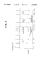
- FIG. 8 is a flow chart showing processing performed by the heartbeat data processing means of the present embodiment.
- FIG. 9 is a flow chart showing processing performed by the heartbeat awareness determination means of the present embodiment along with FIGS. 10 and 11.
- FIG. 10 is a flow chart showing processing performed by the heartbeat awareness determination means of the present embodiment along with FIGS. 9 and 11.
- FIG. 11 is a flow chart showing processing performed by the heartbeat awareness determination means of the present embodiment along with FIGS. 9 and 10.
- FIG. 12 is a schematic enlarged view showing part of the steering shaft to which the steering angle sensor is mounted.
- FIG. 13 is a graph showing a visual steering component of the driver versus steering angle frequency distribution of the steering wheel.
- FIG. 14 is a graph showing a steering angle frequency distribution of the steering wheel when an upward sight limitation is placed on the driver.
- FIG. 15 is a schematic view illustrating an upward sight limitation is on the driver.
- FIG. 16 is a flow chart showing processing performed by the steering angle data processing means of the present embodiment along with FIG. 17.
- FIG. 17 is a flow chart showing processing performed by the steering angle data processing means of the present embodiment along with FIG. 16.
- FIG. 18 is a flow chart showing processing performed by the steering awareness determination means of the present embodiment along with FIG. 19.
- FIG. 19 is a flow chart showing processing performed by the steering awareness determination means of the present embodiment along with FIG. 18.
- FIG. 20 is a flow chart showing warning processing performed by the warning control means of the present embodiment along with FIG. 21.
- FIG. 21 is a flow chart showing warning processing performed by the warning control means of the present embodiment along with FIG. 20.
- FIG. 22 is a flow chart showing processing performed by the steering wheel grip defect warning processing unit of the present embodiment.
- FIG. 23 is a flow chart showing processing performed by the reference value correction unit of the present embodiment.
- FIG. 1 is a flow chart of an embodiment in which the awareness determination apparatus of the present invention is applied to an apparatus for improving the awareness of vehicle drivers
- FIG. 2 is a schematic view showing the interior of the vehicle room in this embodiment.
- a pair of right and left infrared heartbeat sensors 11 and 12 for detecting heartbeat pulses of the driver (not shown) are connected with heartbeat processing means 13 and 14 for receiving detection signals from the infrared heartbeat sensors 11 and 12 and calculating a heartbeat rate of the driver, and the heartbeat processing means 13 and 14 are connected to signal selection means 15, which selects one of the from output signals from either the heartbeat processing means 1S or 14.
- a potential heartbeat sensor 16 which is different from the heartbeat sensors 11 and 12, is connected to heartbeat processing means 17 which receives a detection signal from the potential heartbeat sensor 16 and calculates a heartbeat rate of the driver.
- the signal selection means 15 and the heartbeat processing means 17 are connected with heartbeat data processing means 18 for calculating an average value of the driver's heartbeat rate and a variance thereof according to output signals from the signal selection means 15 and the heartbeat processing means 17, and the heartbeat data processing means 18 is connected to heartbeat awareness determination means 19 for determining an awareness of the driver according to the calculations made by the heartbeat data processing means 18.
- a steering angle sensor 21 for detecting a deviation from a neutral position of a steering shaft 20 (hereinafter referred to as "steering angle") is connected to steering angle data processing means 22 which receives a detection signal from the steering angle sensor 21 and calculates a parameter of frequency analyzed steering component, and the steering angle data processing means is connected to steering awareness determination means for determining an awareness of the driver according to a calculated result from the steering angle data processing means 22.
- the steering angle data processing means 22 of the present embodiment is connected to a vehicle speed sensor 24 for detecting a traveling speed (hereinafter referred to as "vehicle speed") of the vehicle, and a detection signal from the vehicle speed sensor 24 is also input to the steering angle data processing means 22/BF.
- vehicle speed a traveling speed of the vehicle
- the vehicle of the present embodiment is provided with tactile warning means 26 for generating a warning according to deformation of a driver's seat 25, and visual warning means 28 for displaying a warning on a front window 27 of the vehicle, and auditory warning means 29 for generating an audible.
- tactile warning means 26 for generating a warning according to deformation of a driver's seat 25, and visual warning means 28 for displaying a warning on a front window 27 of the vehicle, and auditory warning means 29 for generating an audible.
- These three warning means 26, 28, and 29 are connected to the heartbeat awareness determination means 19 and the steering awareness determination means 29, wherein awareness signals are generated by the heartbeat awareness determination means 19 and the steering awareness determination means 29, and data reflecting the awareness of the driver, are output to warning control means 30, and the warning control means 30 controls operation of the three warning means 26, 28, and 29 according to the awareness signals generated by the heartbeat awareness determination means 19 and the steering awareness determination means 23/BF.
- a warning release switch 31 is provided in the vehicle interior for the driver to terminate warnings output by the three warning means 26, 28, and 29, and the warning release switch 31 is connected to the warning control means 30 and a reference value correction unit
- the reference value correction unit 32 is connected to the heartbeat awareness determination means 19 and the steering awareness determination means 29, and data calculated by the reference value correction unit 32 is input to the heartbeat awareness determination means 19 and the steering awareness determination means 23.
- the above two types of heartbeat sensors 11, 12, and 16 are individually mounted at predetermined positions on a steering wheel 33. Therefore, a mechanism for prompting the driver to grip the steering wheel 33 correctly is provided, because the driver's heartbeat pulse cannot be detected, especially with the potential heartbeat sensor 16, unless the driver grips the steering wheel 33 with both hands at the predetermined positions.
- the vehicle of the present embodiment is provided with steering wheel grip defect warning means whose operation is controlled by the warning control means 30.
- the steering wheel grip defect warning means 34 of the present embodiment uses the two warning means 26 and 29.
- warning control means 30 includes a steering wheel grip defect warning processing unit 95 which receives output signals from the heartbeat processing means 13, 14, and 17 determining whether or not the driver is griping the steering wheel 33 correctly according to output signals from the heartbeat processing means 13, 14, and 17.
- the warning control means 30 operates the steering wheel grip defect warning means 34 when it is determined that the driver is not gripping the steering wheel 33 correctly, and automatically stops operation of the steering wheel grip defect warning means 34 when it is determined that the driver is gripping the steering wheel 33 correctly.
- FIG. 3 An example of changes over time in driver awareness is illustrated in FIG. 3.
- the area (1) indicates a period before the trip
- (2) indicates an awareness decreasing area as a result of continued driving
- (3) indicates an area where awareness increases due to stress resulting from beginning the trip or stress from driving on a city road
- (4) indicates an area where awareness is stable during traveling on a less crowded, monotonous road or a highway
- (5) indicates an area where the awareness of the driver varies because the driver feels sleepy
- (6) indicates an area where the driver is completely unaware because the driver is asleep.
- the infrared heartbeat sensors 11 and 12 which individually function independently utilize a reflection of infrared light by hemoglobin in pulsating blood in the vessel.
- the sensors mainly comprise light projection units 11a and 12a for projecting infrared light and light reception units 11b and 12b for receiving the infrared light, individually incorporated on the right and left sides of the steering wheel 33.
- the structure thereof and the like are already known in Japanese OPI 59-22597 and the like, a detailed description thereof is omitted.
- the potential heartbeat sensor 16 detects a voltage pulse generated by a contraction of the myocardium between both hands of the driver as a pulsed voltage by a pair of electrodes 16a and 16b incorporated in the steering wheel 33 and, since the structure is known in Japanese OPI 59-25729 and the like, further description thereof is omitted.
- infrared heartbeat sensors 11 and 12 may malfunction when strong sunlight is applied to the steering wheel 33, and the potential heartbeat sensor 16 cannot detect the driver's heartbeat if the driver does not grip the steering wheel 33 correctly by both hands, in the present embodiment these two types of heartbeat sensors 11, 12, and 16 are combined as will be described below to accurately detect the driver's heartbeat.
- the heartbeat processing means 1S and 14 calculate the driver's heartbeat rate according to detection signals from the infrared heartbeat sensors 11 and 12, and similarly the heartbeat processing means 17 calculates the driver's heartbeat rate according to a detection signal from the potential heartbeat sensor 16.
- the calculations performed by the heartbeat processing means 13, 14, and 17 are basically the same, in which abnormal detection signals are appropriately corrected to calculate a heartbeat pulse interval (hereinafter referred to as "pulse interval") and the heartbeat rate corresponding to the pulse interval.
- FIG. 4 shows a relationship between heartbeat data calculated by the heartbeat processing means 13, 14, and 17 and the heartbeat pulses detected by the heartbeat sensors, for example, when the pulse interval suddenly becomes shorter than the previously measured pulse interval, the heartbeat calculation according to the pulse interval at that time is temporality reserved, when the sum of the next measured pulse interval and the previous pulse interval is almost the same as the previous pulse interval, the previous heartbeat pulse information is determined to be due to noise, and the previous heartbeat data is canceled.
- pulse intervals I P (n-4) and I P (n-3) at time t P (n-4) and a following time tP.sub.(n-3) are abnormally shorter than a past pulse interval I P .
- the heartbeat rate calculated at the time t P (n-4) is reserved and, when the sum of the two pulse intervals I P (n-4) and I P (n-3) is almost the same as the past pulse interval, the heartbeat pulse at time t t (n-4) is determined to be due to noise, and the heartbeat data at time t P (n-4) is canceled. Further, when the pulse interval suddenly becomes longer, when the next measured pulse interval is almost the same as the past pulse interval, half of the time of the previous pulse interval is added to the time at which the pulse interval before the previous pulse interval was calculated to interpolate heartbeat data at that time.
- the processing flow of the heartbeat processing means 13, 14, and 17 is shown in FIGS. 5 to 7. Processing by the heartbeat processing means 13, 14, and 17 in the present embodiment is made in a predetermined period, for example, every time at an interrupt signal of every 15 msec.
- step a1 the detection time t P of a heartbeat pulse detected by the heartbeat sensors 11, 12, and 16 is read, in step a2, the present pulse detection time t P (n) is subtracted by the previous pulse detection time t P (n-1), and the present pulse interval IP(n) according to the following equation:
- step a3 it is determined in step a3 whether or not a pulse interval reference value I PB is set, however, since the pulse interval reference value I PB is not set at the beginning, processing proceeds to step a4, where a determination is made as to whether or not the pulse interval I P (n) is between a preset minimum pulse interval I MN , For example, 600 msec, and a maximum pulse interval I MX , for example, 1200 msec.
- step a4 When it is determined in step a4 that the pulse interval I P (n) is not between the minimum pulse interval and the maximum pulse interval I MX , that is, the pulse interval I P (n) calculated in step a2 is abnormal, processing returns to step a1 after the above-described interrupt signal of a predetermined period.
- step a4 When it is determined in step a4 that the pulse interval I P (n) is between the minimum pulse interval IMN and the maximum pulse interval I MX , that is, the pulse interval I P (n) calculated in step a2 is a normal value, the pulse interval I P (n) calculated in step a2 is adopted as the reference pulse interval I PB in step a5, and a determination is made in step a6 as to whether or not the present pulse interval I P (n) is longer than the sum of the reference pulse interval I PS and a preset additional time T A , for example, 250 msec. Also, when it is determined in step a3 that the reference pulse interval I PB is set, processing proceeds to step a6.
- step a6 When it is determined in step a6 that the present pulse interval I P (n) is shorter than the sum of the reference pulse interval I PB and the preset additional time T A , that is, the value of the presently calculated pulse interval I P (n) is normal, a determination is made in step a7 as to whether or not the pulse interval I P (n) is shorter than a value of the reference pulse interval I PB subtracted by a preset subtraction time T s , for example, 250 msec, and when it is determined in step a7 that the pulse interval I P (n) is less than the reference pulse interval I PB subtracted by the preset subtraction time T S , that is, the presently calculated pulse interval I P (n) could be abnormal, a determination is made in step a8 as to whether or not a heartbeat data reserve flag F R , which will be described later, is set.
- a heartbeat data reserve flag F R which will be described later
- step a8 When it is determined in step a8 that the heartbeat data reserve flag F R is set, that is the previous determination is reserved because the previously calculated pulse interval I P (n-1) could be abnormal, processing proceeds to step a9, where the present pulse interval I P (n) is corrected to the sum of the present pulse interval I P (n) and the previous pulse interval I P (n-1), and a determination is made again in step a10 as to whether or not the corrected present pulse interval I P (n) is more than the reference pulse interval I PB subtracted by the subtraction time T S and less than the sum of the reference pulse interval IPB and the above additional time T A .
- step a8 When it is determined in step a8 that the heartbeat data reserve flag F R is not set, that is, the previously calculated pulse interval I P (n-1) is normal and the present pulse interval I P (n) is abnormal, processing proceeds to step a11, where the heartbeat data reserve flag F R is set and, in step a12, a first input defect determination flag F U1 , a second input defect determination flag F U2 , and an input normal determination flag F NI , which will be described later, are individually reset, and processing returns to step a1 following the next interrupt signal.
- step a10 When it is determined in step a10 that the pulse interval I P (n) set in step a9 is more than the value of the reference pulse interval I PB subtracted by the preset subtraction time T S and less than the sum of the reference pulse interval I PB and the preset additional time T A , that is, the previous pulse interval I P (n-1) is abnormal, processing proceeds to step a13, where the heartbeat data reserve flag F R is reset.
- a present heartbeat rate R H (n) is calculated in step a14 according to the pulse interval I P (n) corrected in step a9, and a determination is made in step a15 as to whether or not the heartbeat data timer has begun counting up, using the following equation:
- step a15 When it is determined in step a15 that the heartbeat data timer has not begun counting up, counting up of the heartbeat data timer begins in step a16.
- the heartbeat data number N D is incremented by one in step a17, the pulse interval I P (n) set in step a9 is adopted as a new reference pulse interval I PB in step a18, and processing returns to step a1 following the above-described interrupt signal of the predetermined period.
- step a6 when it is determined in step a6 that the pulse interval I P (n) is more than the sum of the reference pulse interval IPB and the preset additional time T A , that is, a heartbeat pulse was expected between the previous time and the present time, processing proceeds to step a19, where the first input defect determination flag F U1 is set, a determination is made in step a20 as to whether or not the input normal determination flag F NI described later is set, that is, the previous input is normal, processing proceeds to step 21, where the previously set pulse interval I P (n) is set as an initial -time of an input defect integrating timer, from which counting up is begun, and a determination is made in step a22 as to whether or not a count value T CI by the input defect integrating timer is longer than a preset time T RI .
- step a22 When it is determined in step a22 that the count value T CI of the input defect integrating timer is less than the above preset time T RI , processing proceeds to step a1 after the above-described predetermined period interrupt signal. Further, when it is determined in step a22 that the count value T CI of the input defect integrating timer exceeds the preset time T RI , that is, the heartbeat pulse data read in step a1 is due to continuous noise, the heartbeat data number N D is set to 0 in step a23, the count value T CR of the heartbeat data timer is reset to 0 in step a24, counting up of the input defect integrating timer is reset in step a25, and processing returns to step a1 following the predetermined period interrupt signal.
- step a20 when it is determined in step a20 that the input normal determination flag F NI is not set, that is, the previous input is abnormal, processing proceeds to step a26, where a determination is made as to whether or not the input defect integrating timer has begun counting up, when it is determined in step a26 that the input defect integrating timer has begun counting up, processing proceeds to the above step a22. On the contrary, when it is determined in step a22 that counting up has not begun by the input defect integrating timer, counting up of the input defect integrating timer begins in step a27, and processing returns to step a1 following the predetermined period interrupt signal.
- step a10 When it is determined in step a10 that the pulse interval I P (n) set in step a9 is shorter than the value of the reference pulse interval I PB subtracted by the subtraction time T S , or the pulse interval I P (n) is longer than the sum of the reference pulse interval IPB and the additional time T A , that is, also the presently corrected pulse interval I P (n) is also abnormal, processing proceeds to step a28, where the second input defect determination flag F U2 is set, and the first input defect determination flag F U1 , the input normal determination flag F NI , and the heartbeat data reserve flag F R are individually reset in step a29, counting up of the input defect integrating timer begins in step a30, and processing returns to step a1 following the predetermined period interrupt signal.
- step a7 when it is determined in step a7 that the pulse interval I P (n) is longer than the value of the reference pulse interval I PB subtracted by the subtraction time T S , that is, the presently calculated pulse interval I P (n) is normal, processing proceeds to step a31, where the normal input determination flag F NI used in the determination step of a20 is set, and a determination is made in step a32 as to whether or not the second input defect determination flag F U2 is set.
- step a32 When it is determined in step a32 that the second input defect determination flag F U2 is set, that is, abnormal heartbeat pulses are detected in two successive times, processing proceeds to step a33, where the count value T CI of the input defect integrating timer is reset to 0, the heartbeat data number N D is reset to 0 in step a34, the count value T CR of the heartbeat data timer is reset to 0 in step a35, and processing proceeds to step a14.
- step a36 a determination is made as to whether or not the first input defect determination flag F U1 is set.
- step a37 a determination is made as to whether or not the count value T CI of the input defect integrating timer is greater than the preset time T RI .
- step a37 When it is expected in step a37 that the count value T CI of the input defect integrating timer is less than the preset time T RI , that is, there was an undetected heartbeat pulse between the previous time and the time before previous time, a heartbeat data interpolation is made for the heartbeat pulse undetected between the previous time and the time before previous time, the first input defect determination flag F U1 is reset in step a39, and processing returns to step a17.
- step a37 When it is determined in step a37 that the count value T CI of the input defect integrating timer is longer than the preset time T RI , that is, the previously calculated pulse interval I P (n-1) is abnormally long, since it is not a normal heartbeat pulse, processing proceeds to step a40, where the heartbeat data number N D is reset to 0, the count value T CR of the heartbeat data timer is reset to 0 in step a41, the count value T CI of the input defect integrating timer is reset to 0, and processing returns to step a1 following the predetermined period interrupt signal.
- Heartbeat data calculated by these heartbeat processing means 13 and 14 should basically be the same but, when the heartbeat data differs for some reason, the signal selection means 15 adopts the one which outputs a greater heartbeat rate from the two heartbeat processing means 13 and 14 in view of control safety, and outputs it to the heartbeat processing means 18. Since the present embodiment employs two infrared heartbeat sensors 11 and 12, an exact heartbeat rate can be calculated even when the steering wheel 33 is gripped by only the right or left hand. In this case, it is natural to adopt the output from heartbeat processing means which outputs normal heartbeat data.
- the heartbeat data processing means 18 calculates an average of heartbeat data of past four times (hereinafter referred to as "4-point running average heartbeat rate”), because there are 3 or 4 heartbeats during a respiration of one time in a rest, considering periodical changes in heartbeat in association with the driver's respiration, to remove fluctuations in heartbeat rate due to the driver's respiration. Further, from the 4-point running average heartbeat rates of the present time, previous time, and the time before previous time, calculation is made as to whether it is a peak point heartbeat rate in which the 4-point running average heartbeat rate of the previous time changes from an increasing tendency to a decreasing tendency, or from a decreasing tendency to an increasing tendency.
- 4-point running average heartbeat rate an average of heartbeat data of past four times
- a gradient of adjacent peak point heartbeat rate obtained by dividing a deviation of adjacent peak point heartbeat rates by the time interval is calculated, and an average of heartbeat rate data of past 10 times (hereinafter referred to as "10-point running average heartbeat rate”) and a simple average of heartbeat rate for past 30 seconds (hereinafter referred to as “30-sec average heartbeat rate”) are calculated.
- step b1 a determination is made in step b1 as to whether or not the heartbeat data number N DI from the signal selection means 15 is more than the heartbeat data number N DE from the potential heartbeat sensor 16, and when it is determined in step b1 that the heartbeat data number N DI from the signal selection means 15 is more than the heartbeat data number N DE from the potential heartbeat sensor 16, processing proceeds to step b2, where the heartbeat data number N DI from one of the infrared heartbeat sensors 11 and 12 through the signal selection means 15 is adopted as an effective heartbeat data number N DA , and a determination is made in step b3 as to whether or not the effective heartbeat data number N DA is more than 4 which is the number of data required for calculating a 4-point running average heartbeat rate R A4 .
- step b1 when it is determined in step b1 that the heartbeat data number from the signal selection means 15 is less than the heartbeat data number N DE from the potential heartbeat sensor 16, processing proceeds to step b4, where the heartbeat data number N DE from the potential heartbeat sensor 16 is adopted as the effective heartbeat data number N DA , and then processing proceeds to step b3.
- step b3 When it is determined in step b3 that the effective heartbeat data number N DA is 4 or more, a 4-point running average heartbeat rate R A4 (n) is calculated in step b5, a peak point index M A1 of the 4-point running average heartbeat rate R A4 is calculated using the equation recited below in step b6, and then a determination is made in step b7 as to whether or not the peak point index M A1 is 0 or less.
- step b3 When it is determined in step b3 that the effective heartbeat data number N DA is less than 4, since the 4-point running average heartbeat rate R A4 (n) cannot be calculated in step b5, processing returns to step b1.
- step b7 When it is determined in step b7 that the peak point index M AI is less than 0, that is, the values are the same only at the present time and the previous time, or the same only at the previous time and at the time before the previous time, or the previous 4-point running average heartbeat rate R A4 (n-1) is greater than the present one and the previous one is greater than the 4-point running average heartbeat rate R A4 (n-2) at the time before previous time, or the present one is greater than the previous 4-point running average heartbeat rate R A4 (n-1) and the 4-point running average heartbeat rate R A4 (n-2) at the time before previous time, processing proceeds to step b8, where the previous 4-point running average heartbeat rate R A4 (n-1) is temporarily adopted as a peak point heartbeat rate R HP (n), a peak point index M PI of a peak point heartbeat rate R HP is calculated using the equation recited below, and a determination is made in step b10 as to whether or not the peak point index M PI is less than 0:
- Ti M P1 ⁇ R HP (n) -R HP (n-1) ⁇ R HP (n-1) -R HP (n-2) ⁇ .
- step b10 When it is determined in step b10 that the peak point index M P1 is smaller than 0, that is, the previous peak point heartbeat rate R HP (n-1) is greater or smaller than the present peak point heartbeat rate R HP (n) and the peak point heartbeat rate R HP (n-2) at the time before the previous time, processing proceeds to step b11, where the previous peak point heartbeat rate R HP (n-1) is registered, a gradient D RH is obtained by dividing a difference between the previously registered peak point heartbeat rate R HP (n-2) and the presently registered peak point heartbeat rate R HP (n-1) by this time is calculated in step b12, and a determination is made in step b13 as to whether or not the effective heartbeat data number N DA is 10 or more which is the number required for calculating a 10-point running average heartbeat rate R A10 .
- step b10 when it is determined in step b10 that the peak point index M PI is 0 or more, that is, the previous peak point heartbeat rate R HP (n-1) is the same as the present time or the time before the previous time, or the magnitudes of the peak point heartbeat rates R HP are in the order of present time, previous time, and the time before previous time, processing proceeds to step b13, where the previous peak point heartbeat rate R HP (n-1) is not registered but reset, and then processing proceeds to step b14.
- step b7 when it is determined in step b7 that the peak point index M AI exceeds 0, that is, if the magnitudes of the peak point heartbeat rates R HP are in the order of present time, previous time, and the time before previous time, then the previous 4-point running average heartbeat rate R A4 (n-1) is not a peak point heartbeat rate, and processing proceeds to step b14.
- step b14 When it is determined in step b14 that the effective heartbeat data number N DA is 10 or more, the 10-point running average heartbeat rate R A10 (n) is calculated in step b15, and a determination is made in step b16 as to whether or not the count value T CR of the heartbeat timer is 30 seconds or more.
- step b13 When it is determined in step b13 that the effective heartbeat data number N DA is less than 10, since the 10-point running average heartbeat rate R A10 (n) cannot be calculated in step b15, the processing returns to step b3.
- step b16 When it is determined in step b16 that the count value T CR of the heartbeat data timer is 30 seconds or more, the 30-sec average heartbeat rate R A30 (n) is calculated in step b17, and processing returns to step b1.
- the processing returns again to step b1.
- the heartbeat awareness determination means 19 determines whether a variation in a heartbeat rate calculated by the heartbeat data processing means 18 is stable, that is, a variation width of the 4-point running average heartbeat rate within 30 seconds falls within 2, for example, and represents an area of stable awareness of the driver as shown in FIG. 3(4), the 30-sec average heartbeat rate R A30 in the area of stable awareness calculated as a reference heartbeat rate and, when the peak point heartbeat rate R HP calculated by the heartbeat data processing means 18 is slightly smaller than the reference heartbeat rate after the driver is determined to be in the area of stable awareness, the driver is determined to be in a transition area in FIG. 3(5), and then the reference heartbeat rate and the present heartbeat data of the driver are compared to determine the awareness of the driver, setting a warning level corresponding to the driver's level of awareness.
- the processing flow of the heartbeat awareness determination means 19 in the present embodiment is shown in FIGS. 9 to 11. Specifically, in the present embodiment, processing by the heartbeat awareness determination means 19 is carried out in a predetermined period, for example, at every interrupt signal of 15 msec. First, a determination is made in step c1 as to whether or not a transition condition experienced flag F SI is set, however, since the transition condition experienced flag F SI is not set at the beginning, processing proceeds to step c2, where a determination is made in step c2 as to whether or not the count value T CR of the heartbeat data timer is 30 seconds or more.
- step c2 When it is determined in step c2 that the count value T CR of the heartbeat data timer is 30 seconds or more, that is, the heartbeat data is normal over a period of 30 seconds or more, the processing proceeds to step c3, where a determination is made as to whether or not an absolute value of the 30-sec average heartbeat rate R A30 (n) subtracted by the 10-point running average heartbeat rate R A10 (n) is 2 or less.
- step c2 determines the count value T CR of the heartbeat data timer is shorter than 30 seconds, that is, the 10-point running average heartbeat rate R A10 (n) cannot be calculated
- the processing returns to step c1 and step c1 is repeated according to the next interrupt signal.
- step c3 When it is determined in step c3 that the absolute value of the 30-sec average heartbeat rate R A30 (n) subtracted by the 10-point running average heartbeat rate R A10 (n) is 2 or less, that is, the heartbeat rate of the driver has almost no variation, a determination is made in step c4 as to whether or not the present peak point heartbeat rate R HP (n) subtracted by the previous peak point heartbeat rate R HP (n-1) is less than 2.
- step c4 When it is determined in step c4 that the absolute value of the present peak point heartbeat rate R HP (n) subtracted by the previous peak point heartbeat rate R HP (n-1) is less than 2, that is, a variation in the peak point heartbeat rate R HP is relatively moderate, a determination is made in step c5 as to whether or not the peak point heartbeat timer has begun counting up. In this case, since counting up of the peak point heartbeat timer has not begun, the processing proceeds to step c6, where counting up of the peak point heartbeat timer is begun, and a determination is made in step c7 as to whether or not the absolute value of a gradient D RH of the present peak point heartbeat rate R HP (n) and the previous peak point heartbeat rate R HPn-1 ) is less than 1. Also, when it is determined in step c5 that the peak point heartbeat timer has begun counting up, the processing proceeds to step c7.
- step c7 When it is determined in step c7 that the absolute value of gradient D RH of the adjacent peak point heartbeat rate R HP is less than 1, that is, the peak point heartbeat rate R HP is increasing or decreasing slightly, the processing proceeds to step c8, where a determination is made as to whether or not a peak point heartbeat gradient timer has begun counting up. In this case, the peak point heartbeat gradient timer does not begin counting up and the processing proceeds to step c9, where the peak point heartbeat timer begins to count up, and a determination is made in step c10 as to whether or not the count value T CP of the peak point heartbeat timer is a predetermined time T RP , for example, 30 seconds, or more. Also, when it is determined in step c8 that the peak point heartbeat gradient timer has begun counting up, the processing proceeds to step c10.
- step c10 When it is determined in step c10 that the count value T CP of the peak point heartbeat timer is the preset time T RP or more, that is, a condition where the variation width of peak point heartbeat rate has continued for a long time, a determination is made in step c11 as to whether or not the count value T CP of the peak point heartbeat gradient timer is the preset time T RP , for example, 30 seconds, or more.
- step c11 When it is determined in step c11 that the count value T CP of the peak point heartbeat gradient timer is more than the preset time T RP , that is, a condition where the peak point heartbeat rate increasing or decreasing slightly has continued for a long time, a stable awareness condition experienced flag F WS is set in step c12, the 30-sec average heartbeat rate R A30 (n) is adopted as a reference heartbeat rate R HB , the count value T CP of the peak point heartbeat timer and the count value T CD of the peak point heartbeat gradient timer are individually reset to 0 in step c14, and the processing returns to step c1 according to the next interrupt signal.
- step c3 when it is determined in step c3 that the absolute value of the 30-sec average heartbeat rate R A30 (n) subtracted by the 10-point running average heartbeat rate R A10 (n) exceeds 2, that is, the change in heartbeat rate of the driver is relatively large, or when it is determined in step c4 that absolute value of the present peak point heartbeat rate R HP (n) subtracted by the previous peak point heartbeat rate R HP (n-1) is 2 or more, that is, the peak point heartbeat rate R HP increases or decreases relatively sharply, or when it is determined in step c7 that the absolute value of gradient D RH of the peak point heartbeat rate R HP is 1 or more, that is, the peak point heartbeat rate R HP increases or decreases relatively sharply, or when it is determined in step c10 that the count value T CP of the peak point heartbeat timer does not reach the preset time T RP , that is, a small variation in the peak point heartbeat rate does not continue for a long time, or when it is determined in step c
- step c15 When it is determined in step c15 that there was a peak point heartbeat rate R HP not smaller than the value of the reference heartbeat rate R HB subtracted by 3 and greater than the reference heartbeat rate R HB subtracted by 2 in the past 20 seconds, that is the driver has entered the transition area, the processing proceeds to step c16, where a transition condition flag F ST is set, and a determination is made in step c17 as to whether or not the stable awareness condition flag F WS is set.
- step c15 When it is determined in step c15 that there was not a peak point heartbeat rate R HP not smaller than the value of the reference heartbeat rate R HB subtracted by 3 and greater than the reference heartbeat rate R HB subtracted by 2 in the past 20 seconds, that is, the driver has not entered the transition area, the processing proceeds to step c17, and when it is determined in step c17 that the stable awareness condition flag F WS is not set, the processing returns to step c1 according to the next interrupt signal.
- step c16 when it is determined in step c16 that the transition condition flag F ST is set, or when it is determined in step c17 that the stable awareness condition flag F WS is set, a determination is made in step c18 as to whether or not a warning preparation flag F PR described later is set. Since the warning preparation flag F PR is not set at the beginning, the processing proceeds to step c19, where a determination is made as to whether or not the value of the reference heartbeat rate R HB subtracted by the present 4-point running average heartbeat rate R A4 (n) exceeds 0 and is less than or equal to 5.
- step c19 When it is determined in step c19 that the value of the reference heartbeat rate R HB subtracted by the present 4-point running average heartbeat rate R A4 (n) exceeds 0 and less than or equal to 5, that is, the awareness of the driver tends to decrease, the warning preparation flag F PR is set in step c20, and the step of c1 and after is repeated according to the next interrupt signal.
- step c18 When it is determined in step c18 that the warning preparation flag F PR is set, that is, the awareness of the driver tends to decrease, the processing proceeds to step c21, where a determination is made as to whether or not the value of the reference heartbeat rate R HB subtracted by the present heartbeat rate R H (n) is less than 5.
- step c21 a determination is made as to whether or not the value of the reference heartbeat rate R HB subtracted by the present heartbeat rate R H (n) is less than 5.
- step c22 the warning level L W is set to the first level, and the processing returns to step c1 according to the next interrupt signal.
- step c21 When it is determined in step c21 that the value of the reference heartbeat rate R HB subtracted by the present heartbeat rate R H (n) is 5 or more, that is, the decrease in heartbeat rate is relatively large, the processing proceeds to step c19.
- step c19 When it is determined in step c19 that the value of the reference heartbeat rate R HB subtracted by the present 4-point running average heartbeat rate R A4 (n) is greater than 5, that is, the decrease in heartbeat rate of the driver is very large, the processing proceeds to step c23, where a determination is made as to whether or not the absolute value of the present peak point heartbeat rate R HP (n) subtracted by the previous peak point heartbeat rate R HP (n-1) is greater than 4.
- step c23 When it is determined in step c23 that the absolute value of the present peak point heartbeat rate R HP (n) subtracted by the previous peak point heartbeat rate R HP (n-1) is greater than 4, that is, the driver is quickly becoming less aware, the processing proceeds to step c24, where a determination is made as to whether or not the adjacent peak point heartbeat timer has begun counting up.
- the adjacent peak point heartbeat timer begins counting up in step c25, the adjacent peak point data number N DB is increased by 1 in step c26, and a determination is made in step c27 as to whether or not the count value T CB of the adjacent peak point heartbeat timer exceeds a preset time T RB , for example, 20 seconds.
- the processing proceeds to step c26.
- step c27 When it is determined in step c27 that the count value T CB of the adjacent peak point heartbeat timer exceeds the preset time T RB , that is, the driver's heartbeat rate varies to a large extent, the processing proceeds to step c28, where the count value T CB of the adjacent peak point heartbeat timer is reset to 0, the adjacent peak point heartbeat data number N DB is also rest to 0 in step 29, the warning level is set to the second level in step c30, and the processing returns to step c1 according to the next interrupt signal.
- step c23 When it is determined in step c23 that the absolute value of the present peak point heartbeat rate R HP (n) subtracted by the previous peak point heartbeat rate R HP (n-1) is 4 or less, that is, the driver's awareness continues to decrease, the processing proceeds to step c30, where the warning level is set to the second level.
- step c27 when it is determined in step c27 that the count, value T CB of the adjacent peak point heartbeat timer is the preset time T RB or less, that is, large variations in the driver's heartbeat rate do not continue for a long time, the processing proceeds to step c31, where a determination is made as to whether or not the adjacent peak point heartbeat data number N DB is more than 3.
- the processing proceeds to step c32, where the warning level is set to the third level, and the processing returns to step c1 according to the next interrupt signal.
- step c30 when it is determined in step c31 that the adjacent peak point heartbeat data number N DB is less than 3, that is, the driver's awareness is not periodically decreasing, the processing proceeds to step c30.
- the driver coarsely steers the steering wheel 33 according to curves in the road, and more finely steers the vehicle according to the road condition. That is, to drive on the road from the present position of the driver to a target position, the steering wheel 33 is coarsely controlled according to the road shape and, when the driver controls the vehicle according to the road condition, the steering wheel 33 is finely steered according to the position of the vehicle relative to the road every moment.
- the fine steering of the steering wheel 33 can be detected to determine the awareness of the driver.
- FIG. 12 illustrates an enlarged cross-sectional structure of the steering shaft 20 to which the steering angle sensor 21 is mounted.
- the steering shaft 20, provided integrally with the steering wheel 93, is rotatably mounted on a steering column 36, the steering shaft 20 is provided with a gear cylinder 37 integrally and coaxially, and the gear cylinder 37 is integrally formed with a drive gear
- the steering column 36 is provided adjacent to the steering shaft 20 with the steering angle sensor 21, which is a potentiometer, a rotary shaft 39 of the steering angle sensor 21 is provided integrally with a drive gear 40 and engaged with a backlash removing gear 41 which is rotatable relative to the drive gear 40.
- the drive gear 38 of the gear cylinder 37 engages with the drive gear 40 and the backlash removing gear 41.
- the steering shaft 20 rotates accordingly, and the drive gear 40 is rotated by the backlash removing gear 41 of which the phase relative to the drive gear 40 is previously adjusted.
- Rotation exactly corresponding to the turning of the steering shaft 20 is transmitted to the rotary shaft 39 of the steering angle sensor 21.
- a turning condition of the steering shaft 20 is exactly detected by the steering angle sensor, which is output as an electrical signal.
- the vehicle speed sensor 24 detects rotation of the output shaft of the transmission (not shown in the present embodiment), however, it is possible to employ other known types of vehicle sensors which detect the vehicle speed according to the rotation speed of the driven wheels.
- the steering angle data processing means 22 calculates a standard value of the steering component which is frequency analyzed to determine the awareness of the driver according to detection signals from the steering angle sensor 21 and the vehicle speed sensor 24, and processes the absolute value of the detection signal of the steering angle sensor 21, which is bandpass filtered using a running average equation to obtain steering angle data. Specifically, the steering angle data is sequentially received every 0.1 sec with a sampling frequency of 10 Hz. The steering angle data is FFT (Fast Fourier Transform) analyzed to obtain magnitudes (power spectrum) of components of individual frequency bands.
- FFT Fast Fourier Transform
- FIG. 13 is a graph showing the obtained frequency distribution of steering angle signal of the steering wheel 33 vs, motion characteristics of the driver, in which the solid lines indicate an ordinary driver with high awareness, and the broken lines indicate the driver with decreased awareness.
- 1 Hz means 1 turn per second of the steering wheel 33
- 0.1 Hz means 1 turn per 10 seconds of the steering wheel 33
- 0.5 Hz means 1 turn per 2 seconds of the steering wheel 33.
- the frequency of fine manipulation of the steering wheel 33 increases with increasing driver awareness
- the frequency of fine manipulation of the steering wheel 33 decreases with decreasing driver awareness. Therefore, it is possible to determine the awareness of the driver by detecting only the area of fine manipulation of the steering wheel 33 and comparing it with a preset reference value.
- detection data is divided into predetermined frequency bands by determining an average value of a plurality of points of every sampling period from the present to the past by a low-pass filter of less than a predetermined frequency, that is, by running average calculation.
- the 0.3-1.0 Hz component of fine manipulation of the steering wheel 33 is set as an area of visual steering component (hereinafter referred to as "visual steering component"), a component of less than 0.3 Hz is cut off because this area represents coarse manipulation of the steering wheel 33 according to curves in the road, and a component of more than 1.0 Hz is also cut off.
- a number M H of samples when the cut-off frequency is 1.0 Hz is calculated.
- a number M L of samples when the cut-off frequency is 0.3 Hz is calculated.
- a 4-point running average steering angle P A4 and a 15-point running average steering angle P A15 of every sampling period from the present and past are calculated and, since the 1 second and 7 seconds, that is, the sampling periods are 0.1 second, a 10-point running average of the 4-point running average visual steering angle P A4 (hereinafter referred to as "10 ⁇ 4 point running average steering angle") P A4-10 , a 70-point running average (hereinafter referred to as "70 ⁇ 4 point running average steering angle") P A4 70, a 10-point running average of the 15-point running average steering angle (hereinafter referred to as "10 ⁇ 15 point running average steering angle") P A15-10 , and a 70-point running average (hereinafter referred to as "70 ⁇ 15 point running average steering angle”) P A15-70 are calculated.
- parameters P S10 and P S70 in the visual steering component area S can be calculated.
- a predetermined traveling test is carried out to determine the visual steering component of an aware driver during ordinary traveling (solid lines) and the visual steering component of an unaware (asleep) driver (broken lines).
- a driver manipulates the steering wheel 33 to trace the traveling lane of the road or his target course in view of the traveling speed based on visual information of "road shape in front of the vehicle” and "present position of the vehicle on the road".
- the present inventors discovered that when part of the visual information is limited, the limitation of visual information affects the operation characteristics of the steering wheel 33. That is, visual steering is controlled mainly by limitation of the driver's visual information, traveling speed, and individual differences on the steering angle frequency response of the steering wheel 33. This was announced at the "Dynamic and Design Conference 1992" of the Society of Mechanical Engineering on Jul. 7-8, 1992, of which test results are briefly described below.
- the fine steering component of the steering wheel 33 that is, the visual steering component can be detected by frequency analyzing steering angle data of the steering wheel 33, and extracting data of the 0.3-1.0 Hz area. Further, as can be seen from the fact that the result agrees with the tendency of the graph shown in FIG. 13, the level of awareness of the driver can be determined from data of the visual steering component area.
- processing flow in the steering angle data processing means 22 in the present embodiment is shown in FIG. 16 and FIG. 17. Specifically, processing by the steering angle data processing means 22 in the present embodiment is performed in a predetermined period, that is, upon receipt of an interrupt signal of every 15 seconds.
- step d1 a steering angle ⁇ from the steering angle sensor 21 and a vehicle speed V from the vehicle speed sensor 24 are read at every sample period of 0.1 second.
- step d2 A determination is made in step d2 as to whether or not the absolute value of the read steering angle ⁇ is less than 10°, when it is determined that the absolute value of the steering angle ⁇ is less than 10°, the processing proceeds to step d3.
- step d4 the past effective steering angle data number N S is reset, and the processing returns to step d1.
- step d3 A determination is made in step d3 as to whether or not the read vehicle speed V is 30 km/h or more, and when it is determined that the vehicle speed V is 30 km/h or more, the processing proceeds to step d5.
- step d4 the steering angle data number N S is reset to 0, and the processing returns again to step d1.
- the vehicle speed V is less than 30 km/h, for example, when the vehicle travels at a low speed on a crowded road is also considered. In such a case, since the driver may perform meaningless manipulations of the steering wheel 33, data which is inappropriate for determining the awareness of the driver may be input. Therefore, as described above, when the absolute value of the steering angle ⁇ is 10° or more or the vehicle speed V is less than 30 km/h, the read steering angle ⁇ is not adopted in step d4.
- step d5 the effective steering angle data number N S adopted in steps d2 and d3 is incremented by 1.
- a determination is made in step d6 as to whether or not the effective steering angle data number N S is 4 or more, and when it is determined to be 4 or more, the processing proceeds to step d7.
- the 4-point running average steering angle P A4 is calculated in step d7, and the processing proceeds to step d8, where the 4-point running average steering angle data number N P4 of the 4-point running average steering angle P A4 calculated in step d7 is incremented by 1.
- the processing returns to step d1.
- step d9 a determination is made as to whether or not the effective steering angle data number N S is 15 or more, and when it is determined to be 15 or more, the processing proceeds to step d10.
- step d10 the 15-point running average steering angle P A15 is calculated, and the processing proceeds to step d11, where the 15-point running average steering angle P A15 is incremented by 1.
- step d9 the processing returns to step d1.
- step d12 a determination is made as to whether or not the 4-point running average steering angle data number N PA is 10 or more, and when it is determined to be 10 or more, the processing proceeds to step d13, where the above-described 10 ⁇ 4 point running average steering angle P A4-10 is calculated, and the processing proceeds to step d14.
- step d14 A determination is made in step d14 as to whether or not the 15-point running average steering angle data number N P15 is 10 or more, and when it is 10 or more, the processing proceeds to step d15, where the above-described 10 ⁇ 15 point running average steering angle P A15-10 is calculated, and the processing proceeds to d16.
- steps d12 and d14 When it is determined in steps d12 and d14 that the 4-point running average steering angle data number N P4 or the 15-point running average steering angle data number N P15 is not 10 or more, since the 10 ⁇ 4 point running average steering angle P A4-10 and the 10 ⁇ 15 point running average steering angle P A15-10 cannot be calculated in steps d13 and d15, the processing returns to step d1.
- step d16 a determination is made as to whether or not the 4-point running average steering angle data number N P4 is 70 or more, and when it is determined to be 70 or more, the processing proceeds to step d17, where the above-described 70 ⁇ 4 point running average steering angle P A4-70 is calculated, and the processing proceeds to step d18.
- step d18 A determination is made in step d18 as to whether or not the 15-point running average steering angle data number N P15 is 70 or more, and when it is 70 or more, the processing proceeds to step d19, where the above-described 70 ⁇ 15 point running average steering angle P A15-70 is calculated.
- step d16 and d18 When it is determined in steps d16 and d18 that the 4-point running average steering angle data number N P4 or the 15-point running average steering angle data number N P15 is not 70 or more, since the 70 ⁇ 4 point running average steering angle P A4-70 and the 70 ⁇ 15 point running average steering angle P A15-70 cannot be calculated in steps d17 and d19, the processing returns to step d1.
- the steering awareness determination means 23 determines the present awareness of the driver according to the reference value (hereinafter referred to as "reference parameter") of a steering component frequency analyzed in the to reflect the awareness of the driver calculated by the steering angle data processing means 22, and sets the warning level corresponding to the awareness level. That is, from the 10 ⁇ 4 point average steering angle P P4-10 and the 70 ⁇ 4 point running average steering angle P A4-70 , and the 10 ⁇ 15 point running average steering angle P A15-10 and the 70 ⁇ 15 point running average steering angle P A15-70 , parameters P S10 and P S70 of the visual steering component area S are calculated by the following equations:
- the parameters P S10 and P S70 of the visual steering component area S are compared with preset reference parameters to determine the level of awareness of the driver.
- step e1 the parameter P S70 of the visual steering component area S is calculated from the absolute value of difference between the 70 ⁇ 4 point running average steering angle P A4-70 and the 70 ⁇ 15 point running average steering angle P A10-70 .
- step e2 A determination is made in step e2 as to whether or not the calculated parameter P S70 of the visual steering component area S is not less than the reference parameter P SS70 , and when the parameter P S70 of the visual steering component area S is less than the reference parameter P SS70 , the processing proceeds to step e3.
- step e3 the parameter P S10 of the visual steering component area S is calculated from the absolute value of difference between the 10 ⁇ 4 point running average steering angle P A4-10 and the 10 ⁇ 15 point running average steering angle P A10-10 .
- a determination is made in step e4 as to whether or not the parameter P S10 of the visual steering component area S is not more than the reference parameter P SS10 , and when-the parameter P S10 of the visual steering component area S is not more than the reference parameter P SS10 , the processing proceeds to step e5.
- the reference parameter is set according to the level of awareness of the driver and, in the present embodiment, 0.21 is set as the reference parameter P SS70 corresponding to the visual steering component parameter P S70 and 0.17 is set as the reference parameter P SS10 corresponding to the visual steering component parameter P S10 .
- the calculated parameters P S10 and P S70 of the visual steering component area S are compared with the reference parameters P SS70 and P SS10 to set the warning level L W .
- the reference parameters P SS70 and P SS10 as described above, are set according to the graph shown in FIG. 13 showing the visual steering components of traveling where the awareness of the driver is low and traveling where the awareness level of the driver is high relative to the frequency distribution. These values are not limited to those in the above embodiment, but may be appropriately set according to various conditions.
- step e6 When it is determined that the parameter P S70 of the visual steering component area S calculated in step e2 is greater than the reference parameter P SS70 , the processing proceeds to step e6.
- step e6 When it is determined that the parameter P S10 of the visual steering ,component area S calculated in step e4 is greater than the reference parameter P SS10 , the processing proceeds to step e6.
- step e6 since the level of awareness of the driver is determined to be high, the count value T CU of the awareness decrease timer is reset to 0, and step e1 is repeated according to the next interrupt signal.
- step e5 a determination is made as to whether or not the awareness decrease timer begins counting up and, when it is determined not to be counting up, counting up of the awareness decrease timer is begun in step e7, a determination is made in step e8 as to whether or not the count value T CU of the awareness decrease timer is not more than a preset time T RU , for example, 3 seconds, that is, P S70 ⁇ P SS70 and P S10 ⁇ P SS10 .
- the processing proceeds to step e6, where the count value T CU of the awareness decrease timer is reset to 0, otherwise, the processing proceeds to step e9.
- step e9 a determination is made as to whether or not a warning change-over timer begins counting up and, when it is determined not to be counting up, counting up of the warning change-over timer begins in step e10, and a determination is made in step e11 as to whether or not the count value T CW of the warning change-over timer is longer than a preset reference warning change-over time T BW added with a preset first additional time T AL , for example, 4 seconds.
- step e12 When it is determined that the count value T CW of the warning change-over timer is longer than the sum of the reference warning change-over time T BW and the first additional time T AL , that is, the awareness level of the driver decreases to its lowest level, the processing proceeds to step e12, where the warning level L W is set to the third level, and the processing proceeds to step e17 which will be described later.
- step e11 When it is determined in step e11 that the count value T CW of the warning change-over timer is not longer than the sum of the reference warning change-over time T BW and the first additional time T AL , the processing proceeds to step e13, where a determination is made as to whether or not the count value T CW of the warning change-over timer is longer than the sum of the reference warning change-over time T BW and a preset second additional time T AS , for example, 3 seconds.
- the processing proceeds to step e14, where the warning level L W is set to the second level.
- step e13 When it is determined in step e13 that the count value T CW of the warning change-over timer is not longer than the sum of the reference warning change-over time T BW and the second additional time T AS , the processing proceeds to step e15, where a determination is made as to whether or not the count value T CW of the warning change-over timer is longer than the reference warning change-over time T BW .
- step e16 When it is determined that the count value T CW of the warning change-over timer is longer than the reference warning change-over time T BW , the processing proceeds to step e16, where the warning level L W is set to the first level, and the processing proceeds to step e17 which will be described later.
- step e14 When it is determined in step e14 that the count value T CW of the warning change-over timer is not more than the reference warning change-over time T BW , the processing proceeds to step e17, where the count value T CU of the awareness decrease timer and the count value T CW of the warning change-over time are individually set to 0, and then the step of e1 is repeated according to the next interrupt signal.
- a pair of right and left side supports 44 provided in the seat back 49 of the driver's seat 25 are made rotatable in the direction of the arrow to repeatedly press the driver's side sitting on the seat 25 from both sides, or separate the side supports 44 from the driver's side, thereby improving the awareness of the driver by tactile excitation.
- the device is adapted to operate when the driver's grip of the steering wheel 33 is not correct, or according to the warning level L W of the first level.
- a display 45 for displaying a sleep drive warning is embedded in the front window 27 in front of the driver's seat 25 which is transparent and does not block the driver's sight when unenergized and, when energized, a sleep warning mark 46 as shown in FIG. 2, for example, is turned on and off in the transparent condition, thereby improving the awareness of the driver by visual excitation.
- the device is adapted to operate according to the warning level L W of the second level.
- the auditory warning means 29 sounds a warning buzzer 48 incorporated in an instrument panel 47 to improve the awareness of the driver by auditory excitation.
- the device is adapted to operate when the driver's grip of the steering wheel 33 is not correct, or according to the warning level L W of the third level.
- the steering wheel grip defect warning means 34 in the present embodiment operates in conjunction with the two warning means 26 and 29. By changing the movement of the side supports 44 and the sound of the warning buzzer 48, the driver can easily distinguish between when the steering wheel 39 is gripped incorrectly and when the awareness level of the driver is decreasing.
- the warning control means 30 controls operation of the three warning means 26, 28, and 29 according to the warning levels L W individually determined by the heartbeat awareness determination means 19 and the steering awareness determination means 23.
- an ON operation signal of the warning release switch 31 is input by the driver, the operation of the three warning means 26, 28, and 29 according to the warning level L W is stopped.
- the warning means 26 and 29 are operated as the steering wheel grip defect warning means 94, the operation of these devices is not stopped even if the driver turns on the warning release switch 31.
- warning processing flow of the warning control means 30 is shown in FIG. 20 and FIG. 21. Specifically, warning processing in the present embodiment is carried out for every interrupt signal of 15 msec, for example. First, a determination is made in step f1 as to whether or not the warning level L W is the first level, and when the warning level L W is the first level, the processing proceeds to step f2, where a determination is made as to whether or not a warning generation flag F WG is set.
- step f2 When it is determined in step f2 that the warning generation flag F WG is not set, the warning generation flag F WG is set in step f3, and counting up of the warning change-over timer begins, and a determination is made in step f4 as to whether or not the count value T CW of the warning change-over timer exceeds the first preset time T WL , for example, 10 seconds.
- step f4 When it is determined in step f4 that the count value T CW of the warning change-over timer is not more than the first preset time T WL , the processing proceeds to step f5, where the tactile warning means 26 is operated to press or separate the side supports 44 relative to the side of the driver, thereby improving the awareness of the driver by tactile excitation, and the processing returns to step f1 according to the next interrupt signal.
- step f2 When it is determined in step f2 that the warning generation flag F WG is set, the processing proceeds to step f4, where a determination is made again as to whether or not the count value T CW of the warning change-over timer exceeds the first preset time T WL .
- step f4 When it is determined in step f4 that the count value T CW of the warning change-over timer exceeds the first preset time T WL , that is, the awareness of the driver is not improved by only the operation of the tactile warning means 26, the processing proceeds to step f6, where the warning level L W is set level, the warning generation flag F WG is reset to 0 in step f7, the count value T CW of the warning change-over timer is reset to 0 in step f8, the visual warning means 28 is operated in step f9 to display the warning mark 46 on the front window 27 to improve the awareness of the driver by visual excitation, and the processing returns to step f1 according to the next interrupt signal.
- step f1 When it is determined in step f1 that the warning level L W is not the first level, the processing proceeds to step f10, where a determination is made as to whether or not the warning level L W is the second level.
- step f10 When it is determined in step f10 that the warning level L W is the second level, the processing proceeds to step f11, where a determination is made as to whether or not the warning generation flag F WG is set.
- the warning generation flag F WG is set in step f12 and the warning change-over timer begins counting up, and a determination is made in step f13 as to whether or not the count value T CW of the warning change-over timer exceeds the first preset time T WL .
- step f13 When it is determined in step f13 that the count value T CW of the warning change-over timer is not more than the first preset time T WL , the processing proceeds to step f9, where the visual warning means 28 is operated to display the warning mark 46 on the front window 27 to improve the awareness of the driver.
- step f11 When it is determined in step f11 that the warning generation flag F WG is set, the processing proceeds to step f13, where a determination is made again as to whether or not the count value T CW of the warning change-over timer exceeds the first preset time T WL .
- step f13 When it is determined in step f13 that the count value T CW of the warning change-over timer exceeds the first preset time T WL , that is, the awareness of the driver is not improved by only the operation of the visual warning means 28, the processing proceeds to step f14, where the warning level L W is set to the third level, the warning generation flag F WG is reset in step f15 and the count value T CW of the warning change-over timer is reset to 0 in step f16, the auditory warning means 29 is operated in step f17 to sound the warning buzzer 48 to improve the awareness of the driver by auditory excitation, and then the processing returns to step f1 according to the next interrupt signal.
- step f10 When it is determined in step f10 that the warning level L W is not the second level, the processing proceeds to step f18, where a determination is made as to whether or not the warning level L W is the third level.
- step f18 When it is determined in step f18 that the warning level L W is the third level, the processing proceeds to step f19, where a determination is made as to whether or not the warning generation flag F WG is set.
- the processing proceeds to step f17, where the auditory warning means 29 is operated to sound the warning buzzer 48 to improve the awareness of the driver.
- step f19 when it is determined in step f19 that the warning generation flag F WG is not set, the processing proceeds to step f20, where the warning generation flag F WG is set, counting up of the warning change-over timer begins in step f21, and then the processing proceeds to step f17.
- step f18 when it is determined in step f18 that the warning level L W is not the third level, the processing proceeds to step f22, where a determination is made as to whether or not the transition condition flag F ST is set.
- step f22 When it is determined that the transition condition flag F ST is set, operation of all three warning means 26, 28, and 29 is stopped in step f23, and the transition condition flag F ST is reset in step f24.
- step f22 determines the processing returns to step f1 according to the next interrupt signal.
- a steering wheel grip defect warning processing unit 35 incorporated in the warning control means 30 estimates a grip of the steering wheel 33 by the driver according to information of an input normal determination flag F NI which is set by the heartbeat processing means 13, 14, and 17 and controls the operation of the steering wheel grip defect warning means 34.
- the steering wheel grip defect warning means 34 controls the tactile warning means 26 to alert the driver and, if unsuccessful, the steering wheel grip defect warning means 34 further operates the auditory warning means 29.
- processing flow in the steering wheel grip defect processing unit 35 of the present embodiment is shown in FIG. 22. Specifically, processing by the steering wheel grip defect processing unit 35 in the present embodiment is carried out at every interrupt signal, for example, of 15 msec.
- a determination is made in step g1 as to whether or not the input normal determination flag F NI is set by the heartbeat processing means 13, 14, and 17, and when the input normal determination flag F NI is not set, that is, the driver's grip of the steering wheel 33 may be incorrect, the processing proceeds to step g2, where a determination is made as to whether or not the count value T CI of an input defect integrating timer is not less than a preset time T RI .
- step g2 When it is determined in step g2 that the count value T CI of the input defect integrating timer is not less than the preset time T RI , a determination is made in step g3 as to whether or not counting up of a steering wheel grip defect warning preparation timer has begun. When it is determined that counting up of the steering wheel grip defect warning preparation timer has not begun, counting up of the steering wheel grip warning preparation timer has begun in step g4, and a determination is made in step g5 as to whether or not the count value T CS of the steering wheel grip defect warning preparation timer exceeds a preset time T RS , for example, 2 seconds.
- T RS preset time
- step g3 when it is determined in step g3 that counting up of the steering wheel grip defect warning preparation timer has begun, the processing proceeds to step g5, where a determination is made as to whether or not the count value T CS of the steering wheel grip defect warning preparation timer exceeds a preset time T RS .
- step g5 When it is determined in step g5 that the count value T CS of the steering wheel grip defect warning preparation timer exceeds a preset time T RS , the processing proceeds to step g6, where a determination is made as to whether or not counting up of the steering wheel grip defect warning preparation timer has begun.
- step g7 When it is determined that counting up of the steering wheel grip defect warning preparation timer has not begun, the processing proceeds to step g7, where counting up of the steering wheel grip defect warning preparation timer is begun, and a determination is made in step g8 as to whether or not the count value T CH of the steering wheel grip defect warning change-over timer exceeds a preset time T RH , for example, 3 seconds.
- step g6 when it is determined in step g6 that the steering wheel defect warning change-over timer begins counting up, the processing proceeds to step g8, where a determination is made as to whether or not the count value T CH of the steering wheel grip defect warning change-over timer exceeds the preset time T RH .
- step g8 When it is determined in step g8 that the count value T CH of the steering wheel grip defect warning change-over timer is not more than the preset time T RH , that is, a time duration where a grip of the steering wheel 33 is incorrect is short, the processing proceeds to step g9, where the tactile warning means 26 is operated to press or separate the side supports 44 to draw the driver's attention to grip the steering wheel 33 correctly, and the processing returns to step g1 according to the next interrupt signal.
- step g8 When it is determined in step g8 that the count value T CH of the steering wheel grip defect warning change-over timer exceeds the preset time T RH , that is, the driver's attention cannot be drawn by only the operation of the tactile warning means 26, the processing proceeds to step g10, where the auditory warning means 28 is operated, while pressing or separating the side supports 44 to the side of the driver, to sound the warning buzzer to draw the driver's attention to grip the steering wheel 33 correctly, by both tactile and auditory warning, and the processing returns to step g1 according to the next interrupt signal.
- step g5 When it is determined in step g5 that the count value T CS of the steering wheel grip defect warning preparation timer is not more than the preset time T RS , the processing returns to step g1 according to the next interrupt signal.
- step g1 When it is determined in step g1 that the input normal determination flag F NI is set, that is, the driver grips the steering wheel 33 correctly, or in step g2 that the count value T CI of the input defect integrating timer is less than the preset time T RI , the processing proceeds to step g13, where the count value T CS of the steering wheel grip defect warning preparation timer is reset to 0, operation of the steering wheel grip defect warning means 34 is stopped, and the processing returns to step g1 according to the next interrupt signal.
- the processing flow of the steering wheel grip defect warning processing unit 35 according to information from the heartbeat processing means 17 corresponding to the potential heartbeat sensor 16 has been described above with reference to FIG. 22. Similar warning processing may be performed in the steering wheel grip defect warning processing unit 35 according to information from the heartbeat processing means 13 and 14 corresponding to the infrared heartbeat sensors 11 and 12.
- the reference value correction unit 32 determines according to a time from operation of the warning means 26, 28, and 29 to the driver's operation of the warning release switch 31, that the awareness of the driver is relatively high when the time is short, and corrects the reference heartbeat rate R HB and the reference warning change-over time T BW to higher values.
- the warning means 26, 28, and 29 determines that the awareness of the driver is lower than expected, corrects the reference heartbeat rate R HB and the reference warning change-over time T BW to lower values so that the warning means 26, 28, and 29 operate earlier, and outputs the corrected reference heartbeat rate R HB and the reference warning change-over time T BW individually to the heartbeat awareness determination means 19 and the steering awareness determination means 23.
- FIG. 23 Processing flow in the reference value correction unit 32 in the present embodiment is shown in FIG. 23.
- the processing in the reference value correction unit 32 in the present embodiment is begun by turning on the warning release switch 31.
- step h1 the warning release flag F ST is set, and determination is made in step h2 as to whether or nor the count value T CW of the warning change-over timer exceeds a second preset time T WM , for example, 6 seconds.
- step h2 When it is determined in step h2 that the count value T CW of the warning change-over timer exceeds the second preset time T WM , that is, reaction of the driver is not very fast, the processing proceeds to step h3, where a determination is made as to whether or not the present warning is a result of information from the steering awareness determination means 29.
- step h4 the reference warning change-over time T BW is re-set to a 1 second smaller value so that the warning means 26, 28, and 29 operate earlier than before. Further, the count value T CW of the warning change-over timer is reset to 0, and then the processing returns to step h1 according to the next interrupt signal.
- step h9 When it is determined in step h9 that the present warning is not a result of information from the steering awareness determination means 23, that is, the warning is a result of information from the heartbeat awareness determination means 19, the processing proceeds to step h6, where the reference heartbeat rate R HB is re-set to a 1 smaller value so that the warning means 26, 28, and 29 operate sooner, and the count value T CW of the warning change-over timer is reset to 0.
- step h2 when it is determined in step h2 that the count value T CW of the warning change-over timer is not more than the second preset time T WM , the processing proceeds to step h7, where a determination is made as to whether or not the count value T CW of the warning change-over timer is shorter than a third preset time T WS , for example, 2 seconds.
- step h8 a determination is made as to whether or not the present warning is a result of information from the steering awareness determination means 23.
- step h8 When it is determined in step h8 that the present warning is a result of information from the steering awareness determination means 23, the processing proceeds to step h9, where the reference warning change-over time T BW is re-set to a 1 second greater value so that the warning means 26, 28, and 29 operate later, and then the processing proceeds to step h5.
- step h8 When it is determined in step h8 that the present warning is not a result of information from the steering awareness determination means 23, that is, the warning is according to information from the heartbeat awareness determination means 19, the processing proceeds to step h10, where the reference heartbeat rate R HB is re-set to 1 greater value so that the warning means 26, 28, and 29 operate later, and the processing proceeds to step h5.
- step h7 When it is determined in step h7 that the count value T CW of the warning change-over timer is not less than the third preset time T WS , the present reference heartbeat rate R HB and the reference warning change-over time T BW are unchanged, and the processing proceeds to step h5, where the count value T CW of the warning change-over timer is reset to 0.
- the awareness determination means determines an index of the awareness of the driver during traveling and compares the index with a preset reference value to determine a decrease in awareness of the driver
- the warning control means controls the warning means according to the output of the awareness determination means and outputs a warning to the driver if the level of awareness of the driver is low.
- the reference value correction means corrects the reference value for determining the awareness according to the response time to the warning from the driver
- the reference value of heartbeat rate is corrected when the awareness determination means compares the index of heartbeat of the driver during traveling with the reference value to determine a decrease in awareness
- the reference value of the steering characteristic parameter of the driver is corrected when the awareness determination means compares the steering characteristic parameter of the driver determined by frequency analyzing the steering angle of the vehicle during traveling with the reference value to determine a decrease in awareness. Therefore, the reference value of heartbeat rate or the steering characteristic parameter can be set according to the individual level of the driver, operation condition, road condition, and the like, thereby improving the accuracy of awareness determination.
Abstract
Description
I.sub.P(n) =t.sub.P(n) -t.sub.P(n-1).
R.sub.H(n) =60/I.sub.P(n).
M.sub.AI ={R.sub.A4(n)-R.sub.A4(n-1) }·{R.sub.A4(n-1) -R.sub.A4(n-2) }.
M=0.443/(I.sub.S ·f).
M.sub.H =0.448/(0.1×1.0).
M.sub.L =0.443/(0.1×0.3).
P.sub.S10 =|P.sub.A4-10 -P.sub.A15-10 |,
P.sub.S70 =|P.sub.A4-70 -P.sub.A15-70 |.
Claims (12)
Applications Claiming Priority (2)
| Application Number | Priority Date | Filing Date | Title |
|---|---|---|---|
| JP5-000785 | 1993-01-06 | ||
| JP00078593A JP3269153B2 (en) | 1993-01-06 | 1993-01-06 | Arousal level determination device |
Publications (1)
| Publication Number | Publication Date |
|---|---|
| US5488353A true US5488353A (en) | 1996-01-30 |
Family
ID=11483357
Family Applications (1)
| Application Number | Title | Priority Date | Filing Date |
|---|---|---|---|
| US08/177,863 Expired - Fee Related US5488353A (en) | 1993-01-06 | 1994-01-04 | Apparatus and method for improving the awareness of vehicle drivers |
Country Status (5)
| Country | Link |
|---|---|
| US (1) | US5488353A (en) |
| EP (1) | EP0605902B1 (en) |
| JP (1) | JP3269153B2 (en) |
| KR (1) | KR970005738B1 (en) |
| DE (1) | DE69310702T2 (en) |
Cited By (63)
| Publication number | Priority date | Publication date | Assignee | Title |
|---|---|---|---|---|
| US5648755A (en) * | 1993-12-29 | 1997-07-15 | Nissan Motor Co., Ltd. | Display system |
| DE19702748A1 (en) * | 1996-03-01 | 1997-09-18 | Kirchlechner Schwarz Monika | Motor vehicle driver condition monitoring method |
| US5694116A (en) * | 1995-11-06 | 1997-12-02 | Honda Giken Kogyo Kabushiki Kaisha | Driver condition-monitoring apparatus for automotive vehicles |
| US5717606A (en) * | 1994-04-26 | 1998-02-10 | Mitsubishi Jidosha Kogyo Kabushiki Kaisha | Apparatus for judging driving attentiveness with respect to a ratio of steering frequency components and a method therefor |
| US5798695A (en) * | 1997-04-02 | 1998-08-25 | Northrop Grumman Corporation | Impaired operator detection and warning system employing analysis of operator control actions |
| US5813989A (en) * | 1994-11-16 | 1998-09-29 | Pioneer Electronic Corporation | Driving mental condition detecting apparatus |
| US5850193A (en) * | 1995-03-30 | 1998-12-15 | Sumitomo Electric Industries, Ltd. | Apparatus for assisting driver in carefully driving |
| US5907282A (en) * | 1997-04-29 | 1999-05-25 | Chris W. Turto | Physiology monitoring sleep prevention system |
| US5925082A (en) * | 1996-02-12 | 1999-07-20 | Honda Giken Kogyo Kabushiki Kaisha | Vehicle steering control system with driver alertness determination |
| US5942979A (en) * | 1997-04-07 | 1999-08-24 | Luppino; Richard | On guard vehicle safety warning system |
| US5983189A (en) * | 1996-08-27 | 1999-11-09 | Samsung Electronics Co., Ltd. | Control device for controlling the starting a vehicle in response to a voice command |
| US6072398A (en) * | 1999-04-20 | 2000-06-06 | Hayes; James | Automatic gas detection system |
| WO2001019249A1 (en) * | 1999-09-14 | 2001-03-22 | Biosys Ab | A method and a system for monitoring a person |
| US6337629B1 (en) | 1999-09-14 | 2002-01-08 | Biosys Ab | Method and a system for monitoring a person |
| WO2002025291A2 (en) * | 2000-09-21 | 2002-03-28 | American Calcar Inc. | Technique for operating a vehicle effectively and safely |
| US6545607B2 (en) * | 2000-05-20 | 2003-04-08 | Integrated Electronic Systems !Sys Consulting Gmbh | Remote control system particularly for remotely controlling industrial equipment |
| US6686845B2 (en) * | 2000-11-24 | 2004-02-03 | Fuji Jukogyo Kabushiki Kaisha | Driver's arousal level estimating apparatus for vehicle and method of estimating arousal level |
| US20040044293A1 (en) * | 1999-01-27 | 2004-03-04 | David Burton | Vigilance monitoring system |
| US20040051642A1 (en) * | 2002-09-18 | 2004-03-18 | Choi Sang J. | Sleepy alarm system activated by heart pulse meter |
| US6734799B2 (en) * | 2001-03-01 | 2004-05-11 | Trw Inc. | Apparatus and method for responding to the health and fitness of a driver of a vehicle |
| US6756903B2 (en) | 2001-05-04 | 2004-06-29 | Sphericon Ltd. | Driver alertness monitoring system |
| US6762684B1 (en) * | 1999-04-19 | 2004-07-13 | Accutrak Systems, Inc. | Monitoring system |
| US20050065663A1 (en) * | 2003-08-26 | 2005-03-24 | Fuji Jukogyo Kabushiki Kaisha | Wakefulness estimating apparatus and method |
| US6950027B2 (en) * | 2000-08-23 | 2005-09-27 | Siemens Vdo Automotive Corporation | Method to alert drowsy driver |
| US20080023253A1 (en) * | 2005-01-19 | 2008-01-31 | Takata-Petri Ag | Steering wheel assembly for a motor vehicle |
| US20080071177A1 (en) * | 2005-04-28 | 2008-03-20 | Pioneer Corporation | Bioinformation Sensor |
| US20080143504A1 (en) * | 2004-12-16 | 2008-06-19 | Angel Ricardo Martin Alvarez | Device to Prevent Accidents in Case of Drowsiness or Distraction of the Driver of a Vehicle |
| US20090040054A1 (en) * | 2007-04-11 | 2009-02-12 | Nec Laboratories America, Inc. | Real-time driving danger level prediction |
| US20090062161A1 (en) * | 2007-08-27 | 2009-03-05 | Joseph Timar | Two-cycle gasoline engine lubricant |
| CN100475143C (en) * | 2004-03-25 | 2009-04-08 | 株式会社三角工具加工 | Load body state judgment device and vehicle seat |
| US20090160631A1 (en) * | 2005-06-09 | 2009-06-25 | Daimler Ag | Method and Control Device for Recognising Inattentiveness According to at Least One Parameter Which is Specific to a Driver |
| US20090174560A1 (en) * | 2008-01-03 | 2009-07-09 | General Electric Company | Systems, Apparatuses And Methods For Monitoring Physical Conditions Of A Vehicle Driver |
| US20090261979A1 (en) * | 1992-05-05 | 2009-10-22 | Breed David S | Driver Fatigue Monitoring System and Method |
| US20090268022A1 (en) * | 2008-04-23 | 2009-10-29 | Toyota Jidosha Kabushiki Kaisha | Wakefulness level estimation apparatus |
| US20090267777A1 (en) * | 2008-04-28 | 2009-10-29 | Ajith Kuttannair Kumar | System and Method For Monitoring An Alertness Of An Operator Of A Powered System |
| US20100063683A1 (en) * | 2005-09-15 | 2010-03-11 | Diedricks Michael Adriaan | An aid for detecting drowsiness of a driver of a vehicle |
| US20100076273A1 (en) * | 2005-10-31 | 2010-03-25 | Toyota Jidosha Kabushiki Kaisha | Detector for state of person |
| US20100168591A1 (en) * | 2008-12-31 | 2010-07-01 | Industrial Technology Research Institute | Drowsiness detection method and apparatus thereof |
| US20140300478A1 (en) * | 2013-04-08 | 2014-10-09 | Denso Corporation | Awareness level improvement device |
| US9129505B2 (en) | 1995-06-07 | 2015-09-08 | American Vehicular Sciences Llc | Driver fatigue monitoring system and method |
| US20150360610A1 (en) * | 2014-06-11 | 2015-12-17 | Ford Global Technologies, Llc | System and Method for Improving Vehicle Wrong-Way Detection |
| US9440657B1 (en) * | 2014-04-17 | 2016-09-13 | State Farm Mutual Automobile Insurance Company | Advanced vehicle operator intelligence system |
| CN106377272A (en) * | 2016-08-30 | 2017-02-08 | 西南交通大学 | Method and system for testing reaction capacity of driver |
| US9786154B1 (en) | 2014-07-21 | 2017-10-10 | State Farm Mutual Automobile Insurance Company | Methods of facilitating emergency assistance |
| US9905108B2 (en) | 2014-09-09 | 2018-02-27 | Torvec, Inc. | Systems, methods, and apparatus for monitoring alertness of an individual utilizing a wearable device and providing notification |
| US9934667B1 (en) | 2014-03-07 | 2018-04-03 | State Farm Mutual Automobile Insurance Company | Vehicle operator emotion management system and method |
| US20180141570A1 (en) * | 2016-11-18 | 2018-05-24 | Toyota Jidosha Kabushiki Kaisha | Vehicle system and vehicle |
| US10134278B1 (en) | 2016-01-22 | 2018-11-20 | State Farm Mutual Automobile Insurance Company | Autonomous vehicle application |
| US10157423B1 (en) | 2014-11-13 | 2018-12-18 | State Farm Mutual Automobile Insurance Company | Autonomous vehicle operating style and mode monitoring |
| US10156848B1 (en) | 2016-01-22 | 2018-12-18 | State Farm Mutual Automobile Insurance Company | Autonomous vehicle routing during emergencies |
| US10223479B1 (en) | 2014-05-20 | 2019-03-05 | State Farm Mutual Automobile Insurance Company | Autonomous vehicle operation feature evaluation |
| US10238335B2 (en) | 2016-02-18 | 2019-03-26 | Curaegis Technologies, Inc. | Alertness prediction system and method |
| US10324463B1 (en) | 2016-01-22 | 2019-06-18 | State Farm Mutual Automobile Insurance Company | Autonomous vehicle operation adjustment based upon route |
| US10373259B1 (en) | 2014-05-20 | 2019-08-06 | State Farm Mutual Automobile Insurance Company | Fully autonomous vehicle insurance pricing |
| US10395332B1 (en) | 2016-01-22 | 2019-08-27 | State Farm Mutual Automobile Insurance Company | Coordinated autonomous vehicle automatic area scanning |
| US10719886B1 (en) | 2014-05-20 | 2020-07-21 | State Farm Mutual Automobile Insurance Company | Accident fault determination for autonomous vehicles |
| US10748419B1 (en) | 2015-08-28 | 2020-08-18 | State Farm Mutual Automobile Insurance Company | Vehicular traffic alerts for avoidance of abnormal traffic conditions |
| US11242051B1 (en) | 2016-01-22 | 2022-02-08 | State Farm Mutual Automobile Insurance Company | Autonomous vehicle action communications |
| US11441916B1 (en) | 2016-01-22 | 2022-09-13 | State Farm Mutual Automobile Insurance Company | Autonomous vehicle trip routing |
| US11580604B1 (en) | 2014-05-20 | 2023-02-14 | State Farm Mutual Automobile Insurance Company | Autonomous vehicle operation feature monitoring and evaluation of effectiveness |
| US11669090B2 (en) | 2014-05-20 | 2023-06-06 | State Farm Mutual Automobile Insurance Company | Autonomous vehicle operation feature monitoring and evaluation of effectiveness |
| US11719545B2 (en) | 2016-01-22 | 2023-08-08 | Hyundai Motor Company | Autonomous vehicle component damage and salvage assessment |
| US11954482B2 (en) | 2022-10-11 | 2024-04-09 | State Farm Mutual Automobile Insurance Company | Autonomous vehicle control assessment and selection |
Families Citing this family (16)
| Publication number | Priority date | Publication date | Assignee | Title |
|---|---|---|---|---|
| WO1998025520A1 (en) * | 1996-12-11 | 1998-06-18 | Olympia Design Gmbh | Safety device for drivers of vehicles, in particular of motor vehicles |
| JPH11245683A (en) * | 1998-02-27 | 1999-09-14 | Nissan Motor Co Ltd | Information presenting device for vehicle |
| GB2343954A (en) * | 1998-11-18 | 2000-05-24 | Edward James Andrews | Vehicle component human condition monitoring system |
| JP4294401B2 (en) * | 2003-07-25 | 2009-07-15 | 富士重工業株式会社 | Vehicle travel support device |
| JPWO2005112764A1 (en) * | 2004-05-24 | 2008-03-27 | パイオニア株式会社 | Biological information detection device |
| JP4710502B2 (en) * | 2005-09-14 | 2011-06-29 | 日産自動車株式会社 | Vehicle dozing prevention device and dozing prevention method |
| DE102011115878B4 (en) * | 2011-10-12 | 2023-06-29 | Volkswagen Ag | Method and device for collision warning in motor vehicles |
| FR3009114B1 (en) * | 2013-07-26 | 2017-01-13 | Delphi France Sas | ACTIVE SAFETY ARRANGEMENT |
| JP2016014542A (en) * | 2014-07-01 | 2016-01-28 | セイコーエプソン株式会社 | Biological information processing system, and control method of biological information processing system |
| JP2016182242A (en) * | 2015-03-26 | 2016-10-20 | パイオニア株式会社 | Drowsiness calculation device |
| JP6720093B2 (en) * | 2017-01-04 | 2020-07-08 | オムロン株式会社 | User terminal |
| DE102017210966A1 (en) * | 2017-06-28 | 2019-01-03 | Volkswagen Aktiengesellschaft | Method and device for operating a motor vehicle with a steering system for the identification of driver interventions |
| JP2020021144A (en) * | 2018-07-30 | 2020-02-06 | パイオニア株式会社 | Stimulus control device, stimulus control method, and program |
| JP7115929B2 (en) * | 2018-07-30 | 2022-08-09 | パイオニア株式会社 | Stimulation control device, stimulation control method and program |
| JP2019093175A (en) * | 2019-02-05 | 2019-06-20 | パイオニア株式会社 | Drowsiness calculation device |
| JP2021003560A (en) * | 2020-08-26 | 2021-01-14 | パイオニア株式会社 | Drowsiness calculation device |
Citations (14)
| Publication number | Priority date | Publication date | Assignee | Title |
|---|---|---|---|---|
| DE2555042A1 (en) * | 1975-12-06 | 1977-06-08 | Stucken Harald Dr | Level of alertness measurement device for humans - has twin electrodes to measure body electrical resistance between extremities |
| CH612340A5 (en) * | 1978-05-19 | 1979-07-31 | Elektromobil Elektro Es Jarmue | Method for monitoring the reaction time of motor vehicle drivers when driving and device for carrying out the method |
| JPS562227A (en) * | 1979-06-13 | 1981-01-10 | Nissan Motor Co Ltd | Dozing drive alarming device |
| FR2485364A1 (en) * | 1980-06-25 | 1981-12-31 | Commissariat Energie Atomique | Skin conductivity measuring circuit - comprises wheatstone bridge with low voltage DC supply, digital meter and can be incorporated in bracelet |
| US4348663A (en) * | 1979-08-29 | 1982-09-07 | Nissan Motor Company, Limited | Safety assurance system for road vehicles |
| US4359725A (en) * | 1979-11-29 | 1982-11-16 | Elektromobil Elektroes Jarmuipari Szovetkezet | Method and apparatus for monitoring the alertness of the driver of a vehicle |
| JPS5922537A (en) * | 1982-07-29 | 1984-02-04 | アイシン精機株式会社 | Cardiac pulse meter on vehicle |
| GB2159111A (en) * | 1984-05-25 | 1985-11-27 | Steering Developments Ltd | Driver assessment system |
| US4572207A (en) * | 1983-05-23 | 1986-02-25 | Nippondenso Co., Ltd. | Pulsimeter for vehicles |
| US4604611A (en) * | 1983-02-18 | 1986-08-05 | Nissan Motor Company, Limited | System and method for detecting driver drowsiness including detection of steering rotation and reversal |
| US4706072A (en) * | 1983-11-30 | 1987-11-10 | Aisin Seiki Kabushiki Kaisha | Human condition monitoring and security controlling apparatus on a road-vehicle |
| DE3826943A1 (en) * | 1988-08-09 | 1990-02-15 | Bosch Gmbh Robert | Evaluation device for physiological data, determined by means of measurement sensors, on patients |
| US4928090A (en) * | 1987-12-09 | 1990-05-22 | Nippondenso Co., Ltd. | Arousal level judging apparatus and method |
| US5311877A (en) * | 1991-10-02 | 1994-05-17 | Mazda Motor Corporation | Waking degree maintaining apparatus |
-
1993
- 1993-01-06 JP JP00078593A patent/JP3269153B2/en not_active Expired - Fee Related
- 1993-12-30 DE DE69310702T patent/DE69310702T2/en not_active Expired - Fee Related
- 1993-12-30 EP EP93121139A patent/EP0605902B1/en not_active Expired - Lifetime
-
1994
- 1994-01-04 US US08/177,863 patent/US5488353A/en not_active Expired - Fee Related
- 1994-01-06 KR KR1019940000269A patent/KR970005738B1/en not_active IP Right Cessation
Patent Citations (14)
| Publication number | Priority date | Publication date | Assignee | Title |
|---|---|---|---|---|
| DE2555042A1 (en) * | 1975-12-06 | 1977-06-08 | Stucken Harald Dr | Level of alertness measurement device for humans - has twin electrodes to measure body electrical resistance between extremities |
| CH612340A5 (en) * | 1978-05-19 | 1979-07-31 | Elektromobil Elektro Es Jarmue | Method for monitoring the reaction time of motor vehicle drivers when driving and device for carrying out the method |
| JPS562227A (en) * | 1979-06-13 | 1981-01-10 | Nissan Motor Co Ltd | Dozing drive alarming device |
| US4348663A (en) * | 1979-08-29 | 1982-09-07 | Nissan Motor Company, Limited | Safety assurance system for road vehicles |
| US4359725A (en) * | 1979-11-29 | 1982-11-16 | Elektromobil Elektroes Jarmuipari Szovetkezet | Method and apparatus for monitoring the alertness of the driver of a vehicle |
| FR2485364A1 (en) * | 1980-06-25 | 1981-12-31 | Commissariat Energie Atomique | Skin conductivity measuring circuit - comprises wheatstone bridge with low voltage DC supply, digital meter and can be incorporated in bracelet |
| JPS5922537A (en) * | 1982-07-29 | 1984-02-04 | アイシン精機株式会社 | Cardiac pulse meter on vehicle |
| US4604611A (en) * | 1983-02-18 | 1986-08-05 | Nissan Motor Company, Limited | System and method for detecting driver drowsiness including detection of steering rotation and reversal |
| US4572207A (en) * | 1983-05-23 | 1986-02-25 | Nippondenso Co., Ltd. | Pulsimeter for vehicles |
| US4706072A (en) * | 1983-11-30 | 1987-11-10 | Aisin Seiki Kabushiki Kaisha | Human condition monitoring and security controlling apparatus on a road-vehicle |
| GB2159111A (en) * | 1984-05-25 | 1985-11-27 | Steering Developments Ltd | Driver assessment system |
| US4928090A (en) * | 1987-12-09 | 1990-05-22 | Nippondenso Co., Ltd. | Arousal level judging apparatus and method |
| DE3826943A1 (en) * | 1988-08-09 | 1990-02-15 | Bosch Gmbh Robert | Evaluation device for physiological data, determined by means of measurement sensors, on patients |
| US5311877A (en) * | 1991-10-02 | 1994-05-17 | Mazda Motor Corporation | Waking degree maintaining apparatus |
Cited By (199)
| Publication number | Priority date | Publication date | Assignee | Title |
|---|---|---|---|---|
| US20090261979A1 (en) * | 1992-05-05 | 2009-10-22 | Breed David S | Driver Fatigue Monitoring System and Method |
| US8604932B2 (en) | 1992-05-05 | 2013-12-10 | American Vehicular Sciences, LLC | Driver fatigue monitoring system and method |
| US5648755A (en) * | 1993-12-29 | 1997-07-15 | Nissan Motor Co., Ltd. | Display system |
| US5717606A (en) * | 1994-04-26 | 1998-02-10 | Mitsubishi Jidosha Kogyo Kabushiki Kaisha | Apparatus for judging driving attentiveness with respect to a ratio of steering frequency components and a method therefor |
| US5813989A (en) * | 1994-11-16 | 1998-09-29 | Pioneer Electronic Corporation | Driving mental condition detecting apparatus |
| US6046671A (en) * | 1995-03-30 | 2000-04-04 | Sumitomo Electric Industries, Ltd. | Apparatus for assisting driver in carefully driving |
| US5850193A (en) * | 1995-03-30 | 1998-12-15 | Sumitomo Electric Industries, Ltd. | Apparatus for assisting driver in carefully driving |
| US9129505B2 (en) | 1995-06-07 | 2015-09-08 | American Vehicular Sciences Llc | Driver fatigue monitoring system and method |
| US5694116A (en) * | 1995-11-06 | 1997-12-02 | Honda Giken Kogyo Kabushiki Kaisha | Driver condition-monitoring apparatus for automotive vehicles |
| US5925082A (en) * | 1996-02-12 | 1999-07-20 | Honda Giken Kogyo Kabushiki Kaisha | Vehicle steering control system with driver alertness determination |
| DE19702748A1 (en) * | 1996-03-01 | 1997-09-18 | Kirchlechner Schwarz Monika | Motor vehicle driver condition monitoring method |
| US5983189A (en) * | 1996-08-27 | 1999-11-09 | Samsung Electronics Co., Ltd. | Control device for controlling the starting a vehicle in response to a voice command |
| US5798695A (en) * | 1997-04-02 | 1998-08-25 | Northrop Grumman Corporation | Impaired operator detection and warning system employing analysis of operator control actions |
| US5942979A (en) * | 1997-04-07 | 1999-08-24 | Luppino; Richard | On guard vehicle safety warning system |
| US5907282A (en) * | 1997-04-29 | 1999-05-25 | Chris W. Turto | Physiology monitoring sleep prevention system |
| US8096946B2 (en) * | 1999-01-27 | 2012-01-17 | Compumedics Limited | Vigilance monitoring system |
| US20040044293A1 (en) * | 1999-01-27 | 2004-03-04 | David Burton | Vigilance monitoring system |
| US6762684B1 (en) * | 1999-04-19 | 2004-07-13 | Accutrak Systems, Inc. | Monitoring system |
| US6072398A (en) * | 1999-04-20 | 2000-06-06 | Hayes; James | Automatic gas detection system |
| WO2001019249A1 (en) * | 1999-09-14 | 2001-03-22 | Biosys Ab | A method and a system for monitoring a person |
| US6337629B1 (en) | 1999-09-14 | 2002-01-08 | Biosys Ab | Method and a system for monitoring a person |
| US6545607B2 (en) * | 2000-05-20 | 2003-04-08 | Integrated Electronic Systems !Sys Consulting Gmbh | Remote control system particularly for remotely controlling industrial equipment |
| US6950027B2 (en) * | 2000-08-23 | 2005-09-27 | Siemens Vdo Automotive Corporation | Method to alert drowsy driver |
| WO2002025291A3 (en) * | 2000-09-21 | 2002-06-20 | American Calcar Inc | Technique for operating a vehicle effectively and safely |
| KR100838804B1 (en) * | 2000-09-21 | 2008-06-17 | 아메리칸 캘카어 인코포레이티드 | Technique for operating a vehicle effectively and safely |
| WO2002025291A2 (en) * | 2000-09-21 | 2002-03-28 | American Calcar Inc. | Technique for operating a vehicle effectively and safely |
| US6686845B2 (en) * | 2000-11-24 | 2004-02-03 | Fuji Jukogyo Kabushiki Kaisha | Driver's arousal level estimating apparatus for vehicle and method of estimating arousal level |
| US6734799B2 (en) * | 2001-03-01 | 2004-05-11 | Trw Inc. | Apparatus and method for responding to the health and fitness of a driver of a vehicle |
| US6756903B2 (en) | 2001-05-04 | 2004-06-29 | Sphericon Ltd. | Driver alertness monitoring system |
| US6791462B2 (en) * | 2002-09-18 | 2004-09-14 | Sang J. Choi | Sleepy alarm system activated by heart pulse meter |
| US20040051642A1 (en) * | 2002-09-18 | 2004-03-18 | Choi Sang J. | Sleepy alarm system activated by heart pulse meter |
| US20050065663A1 (en) * | 2003-08-26 | 2005-03-24 | Fuji Jukogyo Kabushiki Kaisha | Wakefulness estimating apparatus and method |
| US7084773B2 (en) * | 2003-08-26 | 2006-08-01 | Fuji Jukogyo Kabushiki Kaisha | Wakefulness estimating apparatus and method |
| CN100475143C (en) * | 2004-03-25 | 2009-04-08 | 株式会社三角工具加工 | Load body state judgment device and vehicle seat |
| US20080143504A1 (en) * | 2004-12-16 | 2008-06-19 | Angel Ricardo Martin Alvarez | Device to Prevent Accidents in Case of Drowsiness or Distraction of the Driver of a Vehicle |
| US20080023253A1 (en) * | 2005-01-19 | 2008-01-31 | Takata-Petri Ag | Steering wheel assembly for a motor vehicle |
| US7602278B2 (en) | 2005-01-19 | 2009-10-13 | Takata-Petri Ag | Steering wheel assembly for a motor vehicle |
| US7605694B2 (en) * | 2005-01-19 | 2009-10-20 | Takata-Petri Ag | Steering wheel assembly for a motor vehicle |
| US20080023254A1 (en) * | 2005-01-19 | 2008-01-31 | Takata-Petri Ag | Steering wheel assembly for a motor vehicle |
| US20080071177A1 (en) * | 2005-04-28 | 2008-03-20 | Pioneer Corporation | Bioinformation Sensor |
| US20090160631A1 (en) * | 2005-06-09 | 2009-06-25 | Daimler Ag | Method and Control Device for Recognising Inattentiveness According to at Least One Parameter Which is Specific to a Driver |
| US8742936B2 (en) * | 2005-06-09 | 2014-06-03 | Daimler Ag | Method and control device for recognising inattentiveness according to at least one parameter which is specific to a driver |
| US20100063683A1 (en) * | 2005-09-15 | 2010-03-11 | Diedricks Michael Adriaan | An aid for detecting drowsiness of a driver of a vehicle |
| US8199018B2 (en) * | 2005-10-31 | 2012-06-12 | Toyota Jidosha Kabushiki Kaisha | Detector for state of person |
| US20100076273A1 (en) * | 2005-10-31 | 2010-03-25 | Toyota Jidosha Kabushiki Kaisha | Detector for state of person |
| US7839292B2 (en) * | 2007-04-11 | 2010-11-23 | Nec Laboratories America, Inc. | Real-time driving danger level prediction |
| US20090040054A1 (en) * | 2007-04-11 | 2009-02-12 | Nec Laboratories America, Inc. | Real-time driving danger level prediction |
| US20090062161A1 (en) * | 2007-08-27 | 2009-03-05 | Joseph Timar | Two-cycle gasoline engine lubricant |
| US20090174560A1 (en) * | 2008-01-03 | 2009-07-09 | General Electric Company | Systems, Apparatuses And Methods For Monitoring Physical Conditions Of A Vehicle Driver |
| US20090268022A1 (en) * | 2008-04-23 | 2009-10-29 | Toyota Jidosha Kabushiki Kaisha | Wakefulness level estimation apparatus |
| US8823792B2 (en) * | 2008-04-23 | 2014-09-02 | Toyota Jidosha Kabushiki Kaisha | Wakefulness level estimation apparatus |
| US20110205070A1 (en) * | 2008-04-28 | 2011-08-25 | Ajith Kuttannair Kumar | System for monitoring an alertness of an operator of a powered system |
| US8188870B2 (en) | 2008-04-28 | 2012-05-29 | General Electric Company | System for monitoring an alertness of an operator of a powered system |
| US7956757B2 (en) * | 2008-04-28 | 2011-06-07 | General Electric Company | System and method for monitoring an alertness of an operator of a powered system |
| US20090267777A1 (en) * | 2008-04-28 | 2009-10-29 | Ajith Kuttannair Kumar | System and Method For Monitoring An Alertness Of An Operator Of A Powered System |
| EP2204119A1 (en) * | 2008-12-31 | 2010-07-07 | Industrial Technology Research Institute | Drowsiness detection method and apparatus thereof |
| US20100168591A1 (en) * | 2008-12-31 | 2010-07-01 | Industrial Technology Research Institute | Drowsiness detection method and apparatus thereof |
| US20140300478A1 (en) * | 2013-04-08 | 2014-10-09 | Denso Corporation | Awareness level improvement device |
| US9260013B2 (en) * | 2013-04-08 | 2016-02-16 | Denso Corporation | Awareness level improvement device |
| US10593182B1 (en) | 2014-03-07 | 2020-03-17 | State Farm Mutual Automobile Insurance Company | Vehicle operator emotion management system and method |
| US10121345B1 (en) | 2014-03-07 | 2018-11-06 | State Farm Mutual Automobile Insurance Company | Vehicle operator emotion management system and method |
| US9934667B1 (en) | 2014-03-07 | 2018-04-03 | State Farm Mutual Automobile Insurance Company | Vehicle operator emotion management system and method |
| US9908530B1 (en) * | 2014-04-17 | 2018-03-06 | State Farm Mutual Automobile Insurance Company | Advanced vehicle operator intelligence system |
| US9440657B1 (en) * | 2014-04-17 | 2016-09-13 | State Farm Mutual Automobile Insurance Company | Advanced vehicle operator intelligence system |
| US10529027B1 (en) | 2014-05-20 | 2020-01-07 | State Farm Mutual Automobile Insurance Company | Autonomous vehicle operation feature monitoring and evaluation of effectiveness |
| US11080794B2 (en) | 2014-05-20 | 2021-08-03 | State Farm Mutual Automobile Insurance Company | Autonomous vehicle technology effectiveness determination for insurance pricing |
| US10510123B1 (en) | 2014-05-20 | 2019-12-17 | State Farm Mutual Automobile Insurance Company | Accident risk model determination using autonomous vehicle operating data |
| US11869092B2 (en) | 2014-05-20 | 2024-01-09 | State Farm Mutual Automobile Insurance Company | Autonomous vehicle operation feature monitoring and evaluation of effectiveness |
| US11710188B2 (en) | 2014-05-20 | 2023-07-25 | State Farm Mutual Automobile Insurance Company | Autonomous communication feature use and insurance pricing |
| US11669090B2 (en) | 2014-05-20 | 2023-06-06 | State Farm Mutual Automobile Insurance Company | Autonomous vehicle operation feature monitoring and evaluation of effectiveness |
| US11580604B1 (en) | 2014-05-20 | 2023-02-14 | State Farm Mutual Automobile Insurance Company | Autonomous vehicle operation feature monitoring and evaluation of effectiveness |
| US11436685B1 (en) | 2014-05-20 | 2022-09-06 | State Farm Mutual Automobile Insurance Company | Fault determination with autonomous feature use monitoring |
| US11386501B1 (en) | 2014-05-20 | 2022-07-12 | State Farm Mutual Automobile Insurance Company | Accident fault determination for autonomous vehicles |
| US11348182B1 (en) | 2014-05-20 | 2022-05-31 | State Farm Mutual Automobile Insurance Company | Autonomous vehicle operation feature monitoring and evaluation of effectiveness |
| US11288751B1 (en) | 2014-05-20 | 2022-03-29 | State Farm Mutual Automobile Insurance Company | Autonomous vehicle operation feature monitoring and evaluation of effectiveness |
| US11282143B1 (en) | 2014-05-20 | 2022-03-22 | State Farm Mutual Automobile Insurance Company | Fully autonomous vehicle insurance pricing |
| US10223479B1 (en) | 2014-05-20 | 2019-03-05 | State Farm Mutual Automobile Insurance Company | Autonomous vehicle operation feature evaluation |
| US11127086B2 (en) | 2014-05-20 | 2021-09-21 | State Farm Mutual Automobile Insurance Company | Accident fault determination for autonomous vehicles |
| US11127083B1 (en) | 2014-05-20 | 2021-09-21 | State Farm Mutual Automobile Insurance Company | Driver feedback alerts based upon monitoring use of autonomous vehicle operation features |
| US10504306B1 (en) | 2014-05-20 | 2019-12-10 | State Farm Mutual Automobile Insurance Company | Accident response using autonomous vehicle monitoring |
| US11062396B1 (en) | 2014-05-20 | 2021-07-13 | State Farm Mutual Automobile Insurance Company | Determining autonomous vehicle technology performance for insurance pricing and offering |
| US11023629B1 (en) | 2014-05-20 | 2021-06-01 | State Farm Mutual Automobile Insurance Company | Autonomous vehicle operation feature evaluation |
| US11010840B1 (en) | 2014-05-20 | 2021-05-18 | State Farm Mutual Automobile Insurance Company | Fault determination with autonomous feature use monitoring |
| US10963969B1 (en) | 2014-05-20 | 2021-03-30 | State Farm Mutual Automobile Insurance Company | Autonomous communication feature use and insurance pricing |
| US10748218B2 (en) | 2014-05-20 | 2020-08-18 | State Farm Mutual Automobile Insurance Company | Autonomous vehicle technology effectiveness determination for insurance pricing |
| US10354330B1 (en) | 2014-05-20 | 2019-07-16 | State Farm Mutual Automobile Insurance Company | Autonomous feature use monitoring and insurance pricing |
| US10726498B1 (en) | 2014-05-20 | 2020-07-28 | State Farm Mutual Automobile Insurance Company | Accident fault determination for autonomous vehicles |
| US10726499B1 (en) | 2014-05-20 | 2020-07-28 | State Farm Mutual Automoible Insurance Company | Accident fault determination for autonomous vehicles |
| US10373259B1 (en) | 2014-05-20 | 2019-08-06 | State Farm Mutual Automobile Insurance Company | Fully autonomous vehicle insurance pricing |
| US10719886B1 (en) | 2014-05-20 | 2020-07-21 | State Farm Mutual Automobile Insurance Company | Accident fault determination for autonomous vehicles |
| US10719885B1 (en) | 2014-05-20 | 2020-07-21 | State Farm Mutual Automobile Insurance Company | Autonomous feature use monitoring and insurance pricing |
| US10685403B1 (en) | 2014-05-20 | 2020-06-16 | State Farm Mutual Automobile Insurance Company | Fault determination with autonomous feature use monitoring |
| US20150360610A1 (en) * | 2014-06-11 | 2015-12-17 | Ford Global Technologies, Llc | System and Method for Improving Vehicle Wrong-Way Detection |
| US9849834B2 (en) * | 2014-06-11 | 2017-12-26 | Ford Gloabl Technologies, L.L.C. | System and method for improving vehicle wrong-way detection |
| US10540723B1 (en) | 2014-07-21 | 2020-01-21 | State Farm Mutual Automobile Insurance Company | Methods of providing insurance savings based upon telematics and usage-based insurance |
| US11069221B1 (en) | 2014-07-21 | 2021-07-20 | State Farm Mutual Automobile Insurance Company | Methods of facilitating emergency assistance |
| US9783159B1 (en) | 2014-07-21 | 2017-10-10 | State Farm Mutual Automobile Insurance Company | Methods of theft prevention or mitigation |
| US10475127B1 (en) | 2014-07-21 | 2019-11-12 | State Farm Mutual Automobile Insurance Company | Methods of providing insurance savings based upon telematics and insurance incentives |
| US11634102B2 (en) | 2014-07-21 | 2023-04-25 | State Farm Mutual Automobile Insurance Company | Methods of facilitating emergency assistance |
| US10832327B1 (en) | 2014-07-21 | 2020-11-10 | State Farm Mutual Automobile Insurance Company | Methods of providing insurance savings based upon telematics and driving behavior identification |
| US11634103B2 (en) | 2014-07-21 | 2023-04-25 | State Farm Mutual Automobile Insurance Company | Methods of facilitating emergency assistance |
| US10102587B1 (en) | 2014-07-21 | 2018-10-16 | State Farm Mutual Automobile Insurance Company | Methods of pre-generating insurance claims |
| US11565654B2 (en) | 2014-07-21 | 2023-01-31 | State Farm Mutual Automobile Insurance Company | Methods of providing insurance savings based upon telematics and driving behavior identification |
| US9786154B1 (en) | 2014-07-21 | 2017-10-10 | State Farm Mutual Automobile Insurance Company | Methods of facilitating emergency assistance |
| US11257163B1 (en) | 2014-07-21 | 2022-02-22 | State Farm Mutual Automobile Insurance Company | Methods of pre-generating insurance claims |
| US10825326B1 (en) | 2014-07-21 | 2020-11-03 | State Farm Mutual Automobile Insurance Company | Methods of facilitating emergency assistance |
| US11068995B1 (en) | 2014-07-21 | 2021-07-20 | State Farm Mutual Automobile Insurance Company | Methods of reconstructing an accident scene using telematics data |
| US11030696B1 (en) | 2014-07-21 | 2021-06-08 | State Farm Mutual Automobile Insurance Company | Methods of providing insurance savings based upon telematics and anonymous driver data |
| US10387962B1 (en) | 2014-07-21 | 2019-08-20 | State Farm Mutual Automobile Insurance Company | Methods of reconstructing an accident scene using telematics data |
| US10997849B1 (en) | 2014-07-21 | 2021-05-04 | State Farm Mutual Automobile Insurance Company | Methods of facilitating emergency assistance |
| US10974693B1 (en) | 2014-07-21 | 2021-04-13 | State Farm Mutual Automobile Insurance Company | Methods of theft prevention or mitigation |
| US10723312B1 (en) | 2014-07-21 | 2020-07-28 | State Farm Mutual Automobile Insurance Company | Methods of theft prevention or mitigation |
| US9905108B2 (en) | 2014-09-09 | 2018-02-27 | Torvec, Inc. | Systems, methods, and apparatus for monitoring alertness of an individual utilizing a wearable device and providing notification |
| US10055964B2 (en) | 2014-09-09 | 2018-08-21 | Torvec, Inc. | Methods and apparatus for monitoring alertness of an individual utilizing a wearable device and providing notification |
| US10339781B2 (en) | 2014-09-09 | 2019-07-02 | Curaegis Technologies, Inc. | Methods and apparatus for monitoring alterness of an individual utilizing a wearable device and providing notification |
| US10824415B1 (en) | 2014-11-13 | 2020-11-03 | State Farm Automobile Insurance Company | Autonomous vehicle software version assessment |
| US10266180B1 (en) | 2014-11-13 | 2019-04-23 | State Farm Mutual Automobile Insurance Company | Autonomous vehicle control assessment and selection |
| US11748085B2 (en) | 2014-11-13 | 2023-09-05 | State Farm Mutual Automobile Insurance Company | Autonomous vehicle operator identification |
| US11740885B1 (en) | 2014-11-13 | 2023-08-29 | State Farm Mutual Automobile Insurance Company | Autonomous vehicle software version assessment |
| US10821971B1 (en) | 2014-11-13 | 2020-11-03 | State Farm Mutual Automobile Insurance Company | Autonomous vehicle automatic parking |
| US11726763B2 (en) | 2014-11-13 | 2023-08-15 | State Farm Mutual Automobile Insurance Company | Autonomous vehicle automatic parking |
| US11720968B1 (en) | 2014-11-13 | 2023-08-08 | State Farm Mutual Automobile Insurance Company | Autonomous vehicle insurance based upon usage |
| US10431018B1 (en) | 2014-11-13 | 2019-10-01 | State Farm Mutual Automobile Insurance Company | Autonomous vehicle operating status assessment |
| US10824144B1 (en) | 2014-11-13 | 2020-11-03 | State Farm Mutual Automobile Insurance Company | Autonomous vehicle control assessment and selection |
| US10831191B1 (en) | 2014-11-13 | 2020-11-10 | State Farm Mutual Automobile Insurance Company | Autonomous vehicle accident and emergency response |
| US11645064B2 (en) | 2014-11-13 | 2023-05-09 | State Farm Mutual Automobile Insurance Company | Autonomous vehicle accident and emergency response |
| US10416670B1 (en) | 2014-11-13 | 2019-09-17 | State Farm Mutual Automobile Insurance Company | Autonomous vehicle control assessment and selection |
| US10831204B1 (en) | 2014-11-13 | 2020-11-10 | State Farm Mutual Automobile Insurance Company | Autonomous vehicle automatic parking |
| US11532187B1 (en) | 2014-11-13 | 2022-12-20 | State Farm Mutual Automobile Insurance Company | Autonomous vehicle operating status assessment |
| US11500377B1 (en) | 2014-11-13 | 2022-11-15 | State Farm Mutual Automobile Insurance Company | Autonomous vehicle control assessment and selection |
| US10915965B1 (en) | 2014-11-13 | 2021-02-09 | State Farm Mutual Automobile Insurance Company | Autonomous vehicle insurance based upon usage |
| US10940866B1 (en) | 2014-11-13 | 2021-03-09 | State Farm Mutual Automobile Insurance Company | Autonomous vehicle operating status assessment |
| US10943303B1 (en) | 2014-11-13 | 2021-03-09 | State Farm Mutual Automobile Insurance Company | Autonomous vehicle operating style and mode monitoring |
| US11494175B2 (en) | 2014-11-13 | 2022-11-08 | State Farm Mutual Automobile Insurance Company | Autonomous vehicle operating status assessment |
| US10336321B1 (en) | 2014-11-13 | 2019-07-02 | State Farm Mutual Automobile Insurance Company | Autonomous vehicle control assessment and selection |
| US10157423B1 (en) | 2014-11-13 | 2018-12-18 | State Farm Mutual Automobile Insurance Company | Autonomous vehicle operating style and mode monitoring |
| US10353694B1 (en) | 2014-11-13 | 2019-07-16 | State Farm Mutual Automobile Insurance Company | Autonomous vehicle software version assessment |
| US10166994B1 (en) | 2014-11-13 | 2019-01-01 | State Farm Mutual Automobile Insurance Company | Autonomous vehicle operating status assessment |
| US11247670B1 (en) | 2014-11-13 | 2022-02-15 | State Farm Mutual Automobile Insurance Company | Autonomous vehicle control assessment and selection |
| US11173918B1 (en) | 2014-11-13 | 2021-11-16 | State Farm Mutual Automobile Insurance Company | Autonomous vehicle control assessment and selection |
| US11014567B1 (en) | 2014-11-13 | 2021-05-25 | State Farm Mutual Automobile Insurance Company | Autonomous vehicle operator identification |
| US11175660B1 (en) | 2014-11-13 | 2021-11-16 | State Farm Mutual Automobile Insurance Company | Autonomous vehicle control assessment and selection |
| US11127290B1 (en) | 2014-11-13 | 2021-09-21 | State Farm Mutual Automobile Insurance Company | Autonomous vehicle infrastructure communication device |
| US10241509B1 (en) | 2014-11-13 | 2019-03-26 | State Farm Mutual Automobile Insurance Company | Autonomous vehicle control assessment and selection |
| US10246097B1 (en) | 2014-11-13 | 2019-04-02 | State Farm Mutual Automobile Insurance Company | Autonomous vehicle operator identification |
| US10977945B1 (en) | 2015-08-28 | 2021-04-13 | State Farm Mutual Automobile Insurance Company | Vehicular driver warnings |
| US11450206B1 (en) | 2015-08-28 | 2022-09-20 | State Farm Mutual Automobile Insurance Company | Vehicular traffic alerts for avoidance of abnormal traffic conditions |
| US10769954B1 (en) | 2015-08-28 | 2020-09-08 | State Farm Mutual Automobile Insurance Company | Vehicular driver warnings |
| US10748419B1 (en) | 2015-08-28 | 2020-08-18 | State Farm Mutual Automobile Insurance Company | Vehicular traffic alerts for avoidance of abnormal traffic conditions |
| US10950065B1 (en) | 2015-08-28 | 2021-03-16 | State Farm Mutual Automobile Insurance Company | Shared vehicle usage, monitoring and feedback |
| US11181930B1 (en) | 2016-01-22 | 2021-11-23 | State Farm Mutual Automobile Insurance Company | Method and system for enhancing the functionality of a vehicle |
| US11136024B1 (en) | 2016-01-22 | 2021-10-05 | State Farm Mutual Automobile Insurance Company | Detecting and responding to autonomous environment incidents |
| US11022978B1 (en) | 2016-01-22 | 2021-06-01 | State Farm Mutual Automobile Insurance Company | Autonomous vehicle routing during emergencies |
| US11124186B1 (en) | 2016-01-22 | 2021-09-21 | State Farm Mutual Automobile Insurance Company | Autonomous vehicle control signal |
| US11126184B1 (en) | 2016-01-22 | 2021-09-21 | State Farm Mutual Automobile Insurance Company | Autonomous vehicle parking |
| US10295363B1 (en) | 2016-01-22 | 2019-05-21 | State Farm Mutual Automobile Insurance Company | Autonomous operation suitability assessment and mapping |
| US11513521B1 (en) | 2016-01-22 | 2022-11-29 | State Farm Mutual Automobile Insurance Copmany | Autonomous vehicle refueling |
| US11015942B1 (en) | 2016-01-22 | 2021-05-25 | State Farm Mutual Automobile Insurance Company | Autonomous vehicle routing |
| US11016504B1 (en) | 2016-01-22 | 2021-05-25 | State Farm Mutual Automobile Insurance Company | Method and system for repairing a malfunctioning autonomous vehicle |
| US11062414B1 (en) | 2016-01-22 | 2021-07-13 | State Farm Mutual Automobile Insurance Company | System and method for autonomous vehicle ride sharing using facial recognition |
| US11189112B1 (en) | 2016-01-22 | 2021-11-30 | State Farm Mutual Automobile Insurance Company | Autonomous vehicle sensor malfunction detection |
| US11526167B1 (en) | 2016-01-22 | 2022-12-13 | State Farm Mutual Automobile Insurance Company | Autonomous vehicle component maintenance and repair |
| US10324463B1 (en) | 2016-01-22 | 2019-06-18 | State Farm Mutual Automobile Insurance Company | Autonomous vehicle operation adjustment based upon route |
| US10679497B1 (en) | 2016-01-22 | 2020-06-09 | State Farm Mutual Automobile Insurance Company | Autonomous vehicle application |
| US11920938B2 (en) | 2016-01-22 | 2024-03-05 | Hyundai Motor Company | Autonomous electric vehicle charging |
| US10156848B1 (en) | 2016-01-22 | 2018-12-18 | State Farm Mutual Automobile Insurance Company | Autonomous vehicle routing during emergencies |
| US11879742B2 (en) | 2016-01-22 | 2024-01-23 | State Farm Mutual Automobile Insurance Company | Autonomous vehicle application |
| US11348193B1 (en) | 2016-01-22 | 2022-05-31 | State Farm Mutual Automobile Insurance Company | Component damage and salvage assessment |
| US10134278B1 (en) | 2016-01-22 | 2018-11-20 | State Farm Mutual Automobile Insurance Company | Autonomous vehicle application |
| US10503168B1 (en) | 2016-01-22 | 2019-12-10 | State Farm Mutual Automotive Insurance Company | Autonomous vehicle retrieval |
| US10802477B1 (en) | 2016-01-22 | 2020-10-13 | State Farm Mutual Automobile Insurance Company | Virtual testing of autonomous environment control system |
| US11441916B1 (en) | 2016-01-22 | 2022-09-13 | State Farm Mutual Automobile Insurance Company | Autonomous vehicle trip routing |
| US11119477B1 (en) | 2016-01-22 | 2021-09-14 | State Farm Mutual Automobile Insurance Company | Anomalous condition detection and response for autonomous vehicles |
| US10386845B1 (en) | 2016-01-22 | 2019-08-20 | State Farm Mutual Automobile Insurance Company | Autonomous vehicle parking |
| US11440494B1 (en) | 2016-01-22 | 2022-09-13 | State Farm Mutual Automobile Insurance Company | Detecting and responding to autonomous vehicle incidents |
| US10818105B1 (en) | 2016-01-22 | 2020-10-27 | State Farm Mutual Automobile Insurance Company | Sensor malfunction detection |
| US11242051B1 (en) | 2016-01-22 | 2022-02-08 | State Farm Mutual Automobile Insurance Company | Autonomous vehicle action communications |
| US10828999B1 (en) | 2016-01-22 | 2020-11-10 | State Farm Mutual Automobile Insurance Company | Autonomous electric vehicle charging |
| US10395332B1 (en) | 2016-01-22 | 2019-08-27 | State Farm Mutual Automobile Insurance Company | Coordinated autonomous vehicle automatic area scanning |
| US10579070B1 (en) | 2016-01-22 | 2020-03-03 | State Farm Mutual Automobile Insurance Company | Method and system for repairing a malfunctioning autonomous vehicle |
| US10691126B1 (en) | 2016-01-22 | 2020-06-23 | State Farm Mutual Automobile Insurance Company | Autonomous vehicle refueling |
| US11600177B1 (en) | 2016-01-22 | 2023-03-07 | State Farm Mutual Automobile Insurance Company | Autonomous vehicle application |
| US11625802B1 (en) | 2016-01-22 | 2023-04-11 | State Farm Mutual Automobile Insurance Company | Coordinated autonomous vehicle automatic area scanning |
| US10545024B1 (en) | 2016-01-22 | 2020-01-28 | State Farm Mutual Automobile Insurance Company | Autonomous vehicle trip routing |
| US10824145B1 (en) | 2016-01-22 | 2020-11-03 | State Farm Mutual Automobile Insurance Company | Autonomous vehicle component maintenance and repair |
| US10829063B1 (en) | 2016-01-22 | 2020-11-10 | State Farm Mutual Automobile Insurance Company | Autonomous vehicle damage and salvage assessment |
| US11656978B1 (en) | 2016-01-22 | 2023-05-23 | State Farm Mutual Automobile Insurance Company | Virtual testing of autonomous environment control system |
| US10747234B1 (en) | 2016-01-22 | 2020-08-18 | State Farm Mutual Automobile Insurance Company | Method and system for enhancing the functionality of a vehicle |
| US11682244B1 (en) | 2016-01-22 | 2023-06-20 | State Farm Mutual Automobile Insurance Company | Smart home sensor malfunction detection |
| US11719545B2 (en) | 2016-01-22 | 2023-08-08 | Hyundai Motor Company | Autonomous vehicle component damage and salvage assessment |
| US10238335B2 (en) | 2016-02-18 | 2019-03-26 | Curaegis Technologies, Inc. | Alertness prediction system and method |
| US10905372B2 (en) | 2016-02-18 | 2021-02-02 | Curaegis Technologies, Inc. | Alertness prediction system and method |
| US10588567B2 (en) | 2016-02-18 | 2020-03-17 | Curaegis Technologies, Inc. | Alertness prediction system and method |
| CN106377272A (en) * | 2016-08-30 | 2017-02-08 | 西南交通大学 | Method and system for testing reaction capacity of driver |
| CN106377272B (en) * | 2016-08-30 | 2019-07-26 | 西南交通大学 | The test method and system of driver's respond |
| US20180141570A1 (en) * | 2016-11-18 | 2018-05-24 | Toyota Jidosha Kabushiki Kaisha | Vehicle system and vehicle |
| US11577744B2 (en) | 2016-11-18 | 2023-02-14 | Toyota Jidosha Kabushiki Kaisha | Vehicle system and vehicle |
| US10800429B2 (en) * | 2016-11-18 | 2020-10-13 | Toyota Jidosha Kabushiki Kaisha | Vehicle system and vehicle |
| US11954482B2 (en) | 2022-10-11 | 2024-04-09 | State Farm Mutual Automobile Insurance Company | Autonomous vehicle control assessment and selection |
Also Published As
| Publication number | Publication date |
|---|---|
| KR940018765A (en) | 1994-08-18 |
| EP0605902A1 (en) | 1994-07-13 |
| DE69310702D1 (en) | 1997-06-19 |
| DE69310702T2 (en) | 1997-09-25 |
| JP3269153B2 (en) | 2002-03-25 |
| KR970005738B1 (en) | 1997-04-19 |
| EP0605902B1 (en) | 1997-05-14 |
| JPH06197890A (en) | 1994-07-19 |
Similar Documents
| Publication | Publication Date | Title |
|---|---|---|
| US5488353A (en) | Apparatus and method for improving the awareness of vehicle drivers | |
| US5574641A (en) | Apparatus and method for improving the awareness of vehicle drivers | |
| US5769085A (en) | Apparatus for detecting awareness of a vehicle driver and method thereof | |
| US6175793B1 (en) | Gearboxes | |
| JPH07290990A (en) | Driving attention power discriminating method | |
| US20070146164A1 (en) | Parking assistance system and parking assistance method | |
| JP5158677B2 (en) | Driver characteristic detection device | |
| JP3061459B2 (en) | Driver abnormal steering judgment device | |
| JP2009261419A (en) | Biological state estimating device, program, and recording medium | |
| EP1129926A1 (en) | Electric power steering control system and method for controlling electric power steering control system | |
| EP1477370B1 (en) | Biological information of a driver detection apparatus | |
| JPH0622914A (en) | Heart rate detecting device | |
| JP3509839B2 (en) | Arousal level estimation device | |
| CN110403617A (en) | It is a kind of for monitoring the driving assistance method and system of driver's state of mind | |
| JP4051813B2 (en) | Information device | |
| JP3282259B2 (en) | Arousal level determination device | |
| JP2671394B2 (en) | Driver abnormal condition detection device | |
| EP1759957B1 (en) | Method and apparatus for generating a compensated motor velocity output value for an electric power steering motor | |
| JP3992314B2 (en) | Doze driving detection device | |
| JP2869927B2 (en) | Vehicle driving condition monitoring device | |
| JP2884867B2 (en) | Vehicle running status warning device | |
| JPH10100734A (en) | Doze-driving detecting device | |
| JPH06107030A (en) | Dozing driving detection device | |
| JPH0348560B2 (en) | ||
| JPH0796767A (en) | Driver's physical condition detector for vehicle |
Legal Events
| Date | Code | Title | Description |
|---|---|---|---|
| AS | Assignment |
Owner name: MITSUBISHI JIDOSHA KOGYO KABUSHIKI KAISHA, JAPAN Free format text: ASSIGNMENT OF ASSIGNORS INTEREST;ASSIGNORS:KAWAKAMI, YOSHINAKA;TAKIGAWA, YOSHIHARU;ISOMURA, ARIHIRO;AND OTHERS;REEL/FRAME:006929/0146 Effective date: 19940209 |
|
| FEPP | Fee payment procedure |
Free format text: PAYOR NUMBER ASSIGNED (ORIGINAL EVENT CODE: ASPN); ENTITY STATUS OF PATENT OWNER: LARGE ENTITY |
|
| FPAY | Fee payment |
Year of fee payment: 4 |
|
| FPAY | Fee payment |
Year of fee payment: 8 |
|
| AS | Assignment |
Owner name: MITSUBISHI JIDOSHA KOGYO K.K. (A.K.A. MITSUBISHI M Free format text: CHANGE OF ADDRESS;ASSIGNOR:MITSUBISHI JIDOSHA KOGYO K.K.;REEL/FRAME:014601/0865 Effective date: 20030905 |
|
| AS | Assignment |
Owner name: MITSUBISHI JIDOSHA KOGYO K.K. (A.K.A. MITSUBISHI M Free format text: CHANGE OF ADDRESS;ASSIGNOR:MITSUBISHI JIDOSHA KOGYO K.K. (A.K.A. MITSUBISHI MOTORS CORPORATION);REEL/FRAME:019019/0761 Effective date: 20070101 |
|
| REMI | Maintenance fee reminder mailed | ||
| LAPS | Lapse for failure to pay maintenance fees | ||
| STCH | Information on status: patent discontinuation |
Free format text: PATENT EXPIRED DUE TO NONPAYMENT OF MAINTENANCE FEES UNDER 37 CFR 1.362 |
|
| FP | Lapsed due to failure to pay maintenance fee |
Effective date: 20080130 |