US5487836A - Method of cleaning a sintered powdered metal filter - Google Patents
Method of cleaning a sintered powdered metal filter Download PDFInfo
- Publication number
- US5487836A US5487836A US08/371,495 US37149595A US5487836A US 5487836 A US5487836 A US 5487836A US 37149595 A US37149595 A US 37149595A US 5487836 A US5487836 A US 5487836A
- Authority
- US
- United States
- Prior art keywords
- filter
- polymer residue
- polymer
- filter element
- practiced
- Prior art date
- Legal status (The legal status is an assumption and is not a legal conclusion. Google has not performed a legal analysis and makes no representation as to the accuracy of the status listed.)
- Expired - Fee Related
Links
- 238000000034 method Methods 0.000 title claims abstract description 38
- 238000004140 cleaning Methods 0.000 title claims abstract description 22
- 239000012255 powdered metal Substances 0.000 title claims abstract description 11
- 229920000642 polymer Polymers 0.000 claims abstract description 51
- 239000012530 fluid Substances 0.000 claims abstract description 10
- 239000002904 solvent Substances 0.000 claims abstract description 10
- 238000002485 combustion reaction Methods 0.000 claims abstract description 6
- XLYOFNOQVPJJNP-UHFFFAOYSA-N water Substances O XLYOFNOQVPJJNP-UHFFFAOYSA-N 0.000 claims description 25
- LYCAIKOWRPUZTN-UHFFFAOYSA-N ethylene glycol Natural products OCCO LYCAIKOWRPUZTN-UHFFFAOYSA-N 0.000 claims description 21
- KWYUFKZDYYNOTN-UHFFFAOYSA-M Potassium hydroxide Chemical compound [OH-].[K+] KWYUFKZDYYNOTN-UHFFFAOYSA-M 0.000 claims description 15
- -1 steam Substances 0.000 claims description 15
- 238000011010 flushing procedure Methods 0.000 claims description 12
- HEMHJVSKTPXQMS-UHFFFAOYSA-M Sodium hydroxide Chemical compound [OH-].[Na+] HEMHJVSKTPXQMS-UHFFFAOYSA-M 0.000 claims description 9
- 229910052783 alkali metal Inorganic materials 0.000 claims description 7
- 238000001914 filtration Methods 0.000 claims description 7
- CDBYLPFSWZWCQE-UHFFFAOYSA-L Sodium Carbonate Chemical compound [Na+].[Na+].[O-]C([O-])=O CDBYLPFSWZWCQE-UHFFFAOYSA-L 0.000 claims description 6
- MTHSVFCYNBDYFN-UHFFFAOYSA-N diethylene glycol Chemical compound OCCOCCO MTHSVFCYNBDYFN-UHFFFAOYSA-N 0.000 claims description 6
- 239000000155 melt Substances 0.000 claims description 6
- 239000003960 organic solvent Substances 0.000 claims description 6
- BWHMMNNQKKPAPP-UHFFFAOYSA-L potassium carbonate Chemical compound [K+].[K+].[O-]C([O-])=O BWHMMNNQKKPAPP-UHFFFAOYSA-L 0.000 claims description 6
- 239000000203 mixture Substances 0.000 claims description 5
- 238000001035 drying Methods 0.000 claims description 3
- 229910000027 potassium carbonate Inorganic materials 0.000 claims description 3
- 238000000197 pyrolysis Methods 0.000 claims description 3
- 229910000029 sodium carbonate Inorganic materials 0.000 claims description 3
- 238000007664 blowing Methods 0.000 claims description 2
- 238000002844 melting Methods 0.000 claims description 2
- 230000008018 melting Effects 0.000 claims description 2
- 239000011148 porous material Substances 0.000 claims description 2
- ZIBGPFATKBEMQZ-UHFFFAOYSA-N triethylene glycol Chemical compound OCCOCCOCCO ZIBGPFATKBEMQZ-UHFFFAOYSA-N 0.000 claims description 2
- WGCNASOHLSPBMP-UHFFFAOYSA-N hydroxyacetaldehyde Natural products OCC=O WGCNASOHLSPBMP-UHFFFAOYSA-N 0.000 claims 6
- 238000010438 heat treatment Methods 0.000 claims 2
- 238000004506 ultrasonic cleaning Methods 0.000 claims 2
- 238000002156 mixing Methods 0.000 claims 1
- 239000000835 fiber Substances 0.000 description 10
- 230000035699 permeability Effects 0.000 description 7
- 229920002292 Nylon 6 Polymers 0.000 description 6
- 239000002245 particle Substances 0.000 description 6
- 239000007789 gas Substances 0.000 description 4
- 238000004519 manufacturing process Methods 0.000 description 4
- 239000004952 Polyamide Substances 0.000 description 3
- 229940093476 ethylene glycol Drugs 0.000 description 3
- 229920002647 polyamide Polymers 0.000 description 3
- 150000003839 salts Chemical class 0.000 description 3
- 239000000126 substance Substances 0.000 description 3
- QAOWNCQODCNURD-UHFFFAOYSA-N Sulfuric acid Chemical compound OS(O)(=O)=O QAOWNCQODCNURD-UHFFFAOYSA-N 0.000 description 2
- 230000000052 comparative effect Effects 0.000 description 2
- 238000002074 melt spinning Methods 0.000 description 2
- 239000002184 metal Substances 0.000 description 2
- 229910052751 metal Inorganic materials 0.000 description 2
- 229920000728 polyester Polymers 0.000 description 2
- 238000009987 spinning Methods 0.000 description 2
- MHCVCKDNQYMGEX-UHFFFAOYSA-N 1,1'-biphenyl;phenoxybenzene Chemical compound C1=CC=CC=C1C1=CC=CC=C1.C=1C=CC=CC=1OC1=CC=CC=C1 MHCVCKDNQYMGEX-UHFFFAOYSA-N 0.000 description 1
- JHWNWJKBPDFINM-UHFFFAOYSA-N Laurolactam Chemical compound O=C1CCCCCCCCCCCN1 JHWNWJKBPDFINM-UHFFFAOYSA-N 0.000 description 1
- 229920000571 Nylon 11 Polymers 0.000 description 1
- 229920000299 Nylon 12 Polymers 0.000 description 1
- 229920000572 Nylon 6/12 Polymers 0.000 description 1
- 229920006097 Ultramide® Polymers 0.000 description 1
- 238000009835 boiling Methods 0.000 description 1
- 239000006229 carbon black Substances 0.000 description 1
- 239000005539 carbonized material Substances 0.000 description 1
- 239000003795 chemical substances by application Substances 0.000 description 1
- 230000003749 cleanliness Effects 0.000 description 1
- 239000000356 contaminant Substances 0.000 description 1
- 229920001577 copolymer Polymers 0.000 description 1
- YWJUZWOHLHBWQY-UHFFFAOYSA-N decanedioic acid;hexane-1,6-diamine Chemical compound NCCCCCCN.OC(=O)CCCCCCCCC(O)=O YWJUZWOHLHBWQY-UHFFFAOYSA-N 0.000 description 1
- 238000011161 development Methods 0.000 description 1
- 230000018109 developmental process Effects 0.000 description 1
- 238000009826 distribution Methods 0.000 description 1
- ZMUCVNSKULGPQG-UHFFFAOYSA-N dodecanedioic acid;hexane-1,6-diamine Chemical compound NCCCCCCN.OC(=O)CCCCCCCCCCC(O)=O ZMUCVNSKULGPQG-UHFFFAOYSA-N 0.000 description 1
- 230000005611 electricity Effects 0.000 description 1
- 238000005265 energy consumption Methods 0.000 description 1
- 230000007613 environmental effect Effects 0.000 description 1
- 239000004744 fabric Substances 0.000 description 1
- 239000000499 gel Substances 0.000 description 1
- 239000008187 granular material Substances 0.000 description 1
- 239000012535 impurity Substances 0.000 description 1
- 239000010954 inorganic particle Substances 0.000 description 1
- 239000013618 particulate matter Substances 0.000 description 1
- 239000004033 plastic Substances 0.000 description 1
- 229920003023 plastic Polymers 0.000 description 1
- 229920000139 polyethylene terephthalate Polymers 0.000 description 1
- 229920000098 polyolefin Polymers 0.000 description 1
- 239000000843 powder Substances 0.000 description 1
- 230000000717 retained effect Effects 0.000 description 1
- 238000004062 sedimentation Methods 0.000 description 1
- 239000002356 single layer Substances 0.000 description 1
- 239000012815 thermoplastic material Substances 0.000 description 1
Images

Classifications
-
- B—PERFORMING OPERATIONS; TRANSPORTING
- B01—PHYSICAL OR CHEMICAL PROCESSES OR APPARATUS IN GENERAL
- B01D—SEPARATION
- B01D29/00—Filters with filtering elements stationary during filtration, e.g. pressure or suction filters, not covered by groups B01D24/00 - B01D27/00; Filtering elements therefor
- B01D29/11—Filters with filtering elements stationary during filtration, e.g. pressure or suction filters, not covered by groups B01D24/00 - B01D27/00; Filtering elements therefor with bag, cage, hose, tube, sleeve or like filtering elements
- B01D29/31—Self-supporting filtering elements
- B01D29/33—Self-supporting filtering elements arranged for inward flow filtration
-
- B—PERFORMING OPERATIONS; TRANSPORTING
- B01—PHYSICAL OR CHEMICAL PROCESSES OR APPARATUS IN GENERAL
- B01D—SEPARATION
- B01D29/00—Filters with filtering elements stationary during filtration, e.g. pressure or suction filters, not covered by groups B01D24/00 - B01D27/00; Filtering elements therefor
- B01D29/50—Filters with filtering elements stationary during filtration, e.g. pressure or suction filters, not covered by groups B01D24/00 - B01D27/00; Filtering elements therefor with multiple filtering elements, characterised by their mutual disposition
- B01D29/52—Filters with filtering elements stationary during filtration, e.g. pressure or suction filters, not covered by groups B01D24/00 - B01D27/00; Filtering elements therefor with multiple filtering elements, characterised by their mutual disposition in parallel connection
-
- B—PERFORMING OPERATIONS; TRANSPORTING
- B01—PHYSICAL OR CHEMICAL PROCESSES OR APPARATUS IN GENERAL
- B01D—SEPARATION
- B01D29/00—Filters with filtering elements stationary during filtration, e.g. pressure or suction filters, not covered by groups B01D24/00 - B01D27/00; Filtering elements therefor
- B01D29/62—Regenerating the filter material in the filter
- B01D29/66—Regenerating the filter material in the filter by flushing, e.g. counter-current air-bumps
-
- B—PERFORMING OPERATIONS; TRANSPORTING
- B01—PHYSICAL OR CHEMICAL PROCESSES OR APPARATUS IN GENERAL
- B01D—SEPARATION
- B01D2201/00—Details relating to filtering apparatus
- B01D2201/04—Supports for the filtering elements
- B01D2201/043—Filter tubes connected to plates
- B01D2201/0438—Filter tubes connected to plates mounted substantially vertically on plates at the lower side of the filter elements
-
- B—PERFORMING OPERATIONS; TRANSPORTING
- B01—PHYSICAL OR CHEMICAL PROCESSES OR APPARATUS IN GENERAL
- B01D—SEPARATION
- B01D2201/00—Details relating to filtering apparatus
- B01D2201/08—Regeneration of the filter
- B01D2201/085—Regeneration of the filter using another chemical than the liquid to be filtered
Definitions
- the present invention is directed to a method of cleaning a sintered powdered metal filter for the filtration of a polymer melt in an extruder at a spinnerette during the manufacture of fibers, more specifically it is directed to a method of cleaning which comprises a flushing of the filter with a water and air stream against the flow direction of the melt through the filter.
- the depth filter element is made up of a porous structure with thickness and voids which allow particulate matter to be trapped in the interstices and the clean polymer to flow through. This "straining in depth” action of a depth filter is enhanced by changes in the fluid velocity and direction through the porous structure, which results in entrapment and sedimentation of the particles.
- Examples of depth filter elements are wire cloth, random wire fiber, and sintered metal powders.
- the first type of filters can be easily cleaned because the particles are retained on the surface of the filter.
- Cleaning methods for the second filter type are more difficult, and typically involve cleaning with chemical and thermal means with ultrasonics as a post-cleaning step.
- Methods comprise incinerating furnace or oven, salt bath, vacuum oven and fluidized bed.
- Object of the present invention was to provide a method of cleaning depth filter elements, especially sintered metal filters so that the pressure build up after the cleaning is as low as possible and the air permeability through the filter does not derive significantly in comparison to a new filter.
- the present invention is embodied in a method of cleaning polymer residue from a polymer melt filter formed of a sintered powdered metal.
- the polymer residue-contaminated filter is pyrolyzed within a heated chamber at a temperature within the range from about 400° to about 600° C. and for a time sufficient to pyrolyze substantially all of the polymer residue.
- the heated chamber is flushed with steam to prevent combustion of the polymer residue.
- the pyrolyzed filter is then treated with a solvent and back-flushed with a pressurized fluid stream by passing the fluid steam through the filter in a direction opposite to the polymer melt flow therethrough.
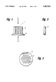
- FIG. 1 shows a side view of a sintered powdered metal filter (1).
- FIG. 2 shows a top view of the sintered powdered metal filter from the flow direction (B).
- FIG. 3 shows a single filter candle (3) of the sintered powdered metal filter.
- FIG. 4 shows the permeability test device (5).
- the method of the present invention is suitable for cleaning depth filter elements for the filtration of polymer melts during the manufacture of fibers by melt spinning of a fiber forming polymer, especially for sintered powdered metal filters.
- Suitable polymers for the manufacture of the fibers according to the present invention are all fiber forming thermoplastic materials especially polyamides, polyesters, and polyolefins.
- Suitable polyamides are nylon 6, nylon 6/6, nylon 6/9, nylon 6/10, nylon 6/12, nylon 11, nylon 12, copolymers thereof and mixtures thereof.
- Preferred polyamides are nylon 6 and nylon 6/6.
- a suitable polyester is polyethylene terepthalate.
- the polymer is fed into an extruder in form of chips or granules, melted and directed via jacketed Dowtherm® (Dow Chemical, Midland Mich.) heated polymer distribution lines to the spinning head, where it is filtered by a depth filter element like the one shown in FIG. 1 and extruded through a spinnerette plate with capillaries to form the fibers.
- Dowtherm® Dow Chemical, Midland Mich.
- FIG. 1 shows an example of a sintered powdered metal filter (1) with a filter plate (2) and a plurality of filter candles (3).
- (A) shows the flow direction of the polymer melt and
- (B) shows the direction of the flushing of the filter with water and air stream.
- FIG. 2 shows a top view of the sintered powdered metal filter (1) from the flow direction (B) with openings (4) for the filter candles (3).
- FIG. 3 shows a single filter candle (3).
- One type of filter is commercially available under Mott® filter from Company Mott Metallurgical Corp., U.S.A.
- a suitable filter for the present invention has from about 1 to about 200 candles, preferably from about 5 to about 42 candles.
- the candles have capillary diameters from about 1 to about 50 microns, preferably from about 2 to about 40 microns, most preferred from about 2 to about 10 microns.
- the filter is treated at a temperature of from about 400° to about 600° C., preferably from about 460° to about 510° C. for the pyrolysis of the polymer. This may be done in an incinerating furnace or oven, a salt bath, a vacuum oven or a fluidized bed. An oven like a Lindberg oven (Lindberg, U.S.A.) is preferred.
- the Lindberg oven requires only electricity and water.
- the parts are placed in a heated chamber, flushed with steam to prevent any combustion from taking place.
- the polymer is heated above the melting point. Approximately 90% of the polymer drips from the parts into a trap in the bottom of the oven where it solidifies and is removed. The remainder of the polymer is pyrolyzed and the gases are removed by the steam.
- the advantages of the Lindberg oven are moderate energy consumption, good temperature control, safe operation and no environmental controls required.
- step (b) After the filter is removed from the chamber it is treated in step (b) with at least one solvent.
- the preferred solvent is water.
- the filter is put in the water at a temperature from about 20° to 100° C., preferably 50° to 100° C. for a time period of from about 1 minute to about 1 hour, preferably from about 2 minutes to about 20 minutes.
- Suitable organic solvents are alkylene glycols like ethylene glycol, diethylene glycol and triethylene glycol.
- the organic solvents may contain an alkali metal salt like sodium carbonate, potassium carbonate, sodium hydroxide or potassium hydroxide in an amount of from about 5% to about 50% by weight based on the weight of the total mixture of solvent and salt.
- an alkali metal salt like sodium carbonate, potassium carbonate, sodium hydroxide or potassium hydroxide in an amount of from about 5% to about 50% by weight based on the weight of the total mixture of solvent and salt.
- the filter is treated with this solvent at a temperature of from about 140° to about 200° C., preferably from about 150° to about 190° C. over a time period of from about 1 minute to about 3 hours, preferably from about 1 hour to 2 hours.
- step (c) flushing the filter with a stream of water, steam or air against the flow direction of the melt through the filter.
- the steam is under a pressure of from about 60 to about 100 psig, preferably from about 80 to about 90 psig.
- Preferred is a water and air stream.
- the filter is dried for example by blowing air through the filter or placing it in a warm oven or both.
- an additional step may be added by treating the filter in an ultra sonic water bath for about 1 minute to about 5 hours, preferably from about 1 hour to about 3 hours.
- a suitable ultrasonic device is Sonic bath Intex 8667C from Lewis Corp., U.S.A.
- This optional step is followed by drying the filter.
- the degree of cleanliness is measured in an air permeability test, which is shown in FIG. 4:
- the filter (1) is fixed over a gas chamber (7) in a block (6), having a gas channel (8), which is connected to a manometer (9).
- the arrow shows the direction of the air, which flows through the filter (1) and to the manometer (9).
- the cleaner the filter (1) the higher is the gas permeability and the more air flows through the filter, showing a low pressure on the manometer. If the filter is blocked by particles the permeability is lower and a pressure build up is shown by the manometer.
- the scale of the manometer ranges from 0 to 39 inches of water.
- Nylon 6 (Ultramid® BS-700 of BASF AG, Ludwigshafen, Germany) with a relative viscosity of 2.7 (1 g in 100 ml 96% by weight of sulfuric acid at 25° C.) with 1% by weight of carbon black was extruded and filtered through a Mott® filter with 19 candles with a capillary diameter of 3 microns for one week. After removing the filter it was placed in a Lindberg oven at 510° C. for three hours and five minutes. The oven was flushed with steam during this time period. After removing the filter from the oven it was placed in boiling water and placed into an ethyleneglycol bath with 10% potassium hydroxide at a temperature of 150° C. for 11/2 hours.
- the filter was removed from this bath and mixed with water of 60° C.
- the filter was placed up side down and flushed with a jet gun with 90 psig air and water against the flow direction of the polymer, which is the (B) direction.
- the filter is washed again with water for 5 to 15 seconds and placed in a sonic bath (Intex 8667C) at 70° C. up side down for 11/2 hours.
- the filter is then placed in hot water at 75° C. and blown dry with 90 psig air followed by placing it in a warm oven overnight to dry.
- Example 1 was repeated with another Mott® filter with 19 candles with a capillary diameter of 3 microns.
- Example 1 was repeated without the flushing step with the jet gun against the flow direction of the polymer melt.
- the filter could not be reused a second time because the permeability was too low.
Abstract
Description
              TABLE
______________________________________
Pressure (inches of water)
                       After 1  After 2
Examples   New Filter  Cleaning Cleanings
______________________________________
1          14          16.5     16.4
2          14          15.5     15.4
3          14          >39      Not reusable
(comparative)
______________________________________
Claims (24)
Priority Applications (1)
| Application Number | Priority Date | Filing Date | Title |
|---|---|---|---|
| US08/371,495 US5487836A (en) | 1993-06-23 | 1995-01-11 | Method of cleaning a sintered powdered metal filter |
Applications Claiming Priority (2)
| Application Number | Priority Date | Filing Date | Title |
|---|---|---|---|
| US8157593A | 1993-06-23 | 1993-06-23 | |
| US08/371,495 US5487836A (en) | 1993-06-23 | 1995-01-11 | Method of cleaning a sintered powdered metal filter |
Related Parent Applications (1)
| Application Number | Title | Priority Date | Filing Date |
|---|---|---|---|
| US8157593A Continuation | 1993-06-23 | 1993-06-23 |
Publications (1)
| Publication Number | Publication Date |
|---|---|
| US5487836A true US5487836A (en) | 1996-01-30 |
Family
ID=22165022
Family Applications (1)
| Application Number | Title | Priority Date | Filing Date |
|---|---|---|---|
| US08/371,495 Expired - Fee Related US5487836A (en) | 1993-06-23 | 1995-01-11 | Method of cleaning a sintered powdered metal filter |
Country Status (1)
| Country | Link |
|---|---|
| US (1) | US5487836A (en) |
Cited By (9)
| Publication number | Priority date | Publication date | Assignee | Title |
|---|---|---|---|---|
| US5945006A (en) * | 1996-02-29 | 1999-08-31 | Movengineering S.R.L. | Method and apparatus for cleaning filters contaminated by polymers and hot-melting resins, in situ, without removing the filtering elements |
| US5972230A (en) * | 1997-08-28 | 1999-10-26 | Kaiser Aluminum And Chemical Corporation | Method for rejuvenation of filter elements used in the filtration of metalworking fluids |
| US6568406B2 (en) * | 1997-10-22 | 2003-05-27 | Basf Aktiengesellschaft | Method of cleaning plant parts for the preparation or processing of (meth)acrylic esters |
| US6644326B2 (en) | 2001-09-05 | 2003-11-11 | Michael R. Dorton | Process for cleaning polymeric fouling from equipment |
| US20070051390A1 (en) * | 2003-05-29 | 2007-03-08 | Norris Peter J | Cleaning filter components |
| US20110308543A1 (en) * | 2010-06-22 | 2011-12-22 | Conocophillips Company | Method for cleaning porous metallic filters using a steam-ultrasonic technique |
| US20170291196A1 (en) * | 2016-04-06 | 2017-10-12 | Asml Netherlands B.V. | System Method and Apparatus for High Pressure Liquid Jet Cleaning of Sintered Filters |
| JP2018187603A (en) * | 2017-05-11 | 2018-11-29 | 株式会社カネカ | Method for manufacturing regeneration filter, regeneration filter, and method for manufacturing molding of thermoplastic resin composition |
| CN114147237A (en) * | 2021-11-30 | 2022-03-08 | 西北有色金属研究院 | Cleaning method for residual powder in pore channel of additive manufacturing porous tantalum material |
Citations (8)
| Publication number | Priority date | Publication date | Assignee | Title |
|---|---|---|---|---|
| US3084076A (en) * | 1960-04-11 | 1963-04-02 | Dow Chemical Co | Chemical cleaning of metal surfaces employing steam |
| US3788486A (en) * | 1971-09-30 | 1974-01-29 | Minnesota Mining & Mfg | Filter |
| US3865628A (en) * | 1973-02-26 | 1975-02-11 | Cesco Inc | Removal of polymer residue from surfaces of processing equipment |
| US4200471A (en) * | 1976-12-22 | 1980-04-29 | Hoechst Aktiengesellschaft | Process for cleaning spinnerets |
| US4493756A (en) * | 1983-06-21 | 1985-01-15 | Pall Corporation | Process for cleaning metal filters |
| US4954180A (en) * | 1987-05-15 | 1990-09-04 | James Christopher Malloy | Method for cleaning spinnerettes |
| US5240613A (en) * | 1991-08-15 | 1993-08-31 | Maruzen Petrochemical Co., Ltd. | Process for regenerating clogged filters |
| US5246589A (en) * | 1991-12-17 | 1993-09-21 | Wellman, Inc. | Repaired filtration elements for polymer manufacture |
-
1995
- 1995-01-11 US US08/371,495 patent/US5487836A/en not_active Expired - Fee Related
Patent Citations (8)
| Publication number | Priority date | Publication date | Assignee | Title |
|---|---|---|---|---|
| US3084076A (en) * | 1960-04-11 | 1963-04-02 | Dow Chemical Co | Chemical cleaning of metal surfaces employing steam |
| US3788486A (en) * | 1971-09-30 | 1974-01-29 | Minnesota Mining & Mfg | Filter |
| US3865628A (en) * | 1973-02-26 | 1975-02-11 | Cesco Inc | Removal of polymer residue from surfaces of processing equipment |
| US4200471A (en) * | 1976-12-22 | 1980-04-29 | Hoechst Aktiengesellschaft | Process for cleaning spinnerets |
| US4493756A (en) * | 1983-06-21 | 1985-01-15 | Pall Corporation | Process for cleaning metal filters |
| US4954180A (en) * | 1987-05-15 | 1990-09-04 | James Christopher Malloy | Method for cleaning spinnerettes |
| US5240613A (en) * | 1991-08-15 | 1993-08-31 | Maruzen Petrochemical Co., Ltd. | Process for regenerating clogged filters |
| US5246589A (en) * | 1991-12-17 | 1993-09-21 | Wellman, Inc. | Repaired filtration elements for polymer manufacture |
Non-Patent Citations (10)
| Title |
|---|
| Chemiefasern/Textilindustrie, vol. 34/86 (Jun. 1984), pp. 409 411 translated by J. Cornelsen. * |
| Chemiefasern/Textilindustrie, vol. 34/86 (Jun. 1984), pp. 409-411 translated by J. Cornelsen. |
| Engineering Report No. 1 12 by Fuji Filter Manufacturing Co., Ltd., Charlotte, N.C. (Jan. 1992). * |
| Engineering Report No. 1-12 by Fuji Filter Manufacturing Co., Ltd., Charlotte, N.C. (Jan. 1992). |
| F. Fourne, Chemiefasern/Textilindustrie, vol. 35/87 (Jun. 1985), pp. 397 403. * |
| F. Fourne, Chemiefasern/Textilindustrie, vol. 35/87 (Jun. 1985), pp. 397-403. |
| F. Fourne, Kunststoffe, 79 (1989) 9, pp. 807 813. * |
| F. Fourne, Kunststoffe, 79 (1989) 9, pp. 807-813. |
| R. E. Duffy, "Basic Methods for Removing Polymer from Parts", International Fiber Journal (Jun. 1991). |
| R. E. Duffy, Basic Methods for Removing Polymer from Parts , International Fiber Journal (Jun. 1991). * |
Cited By (14)
| Publication number | Priority date | Publication date | Assignee | Title |
|---|---|---|---|---|
| US5945006A (en) * | 1996-02-29 | 1999-08-31 | Movengineering S.R.L. | Method and apparatus for cleaning filters contaminated by polymers and hot-melting resins, in situ, without removing the filtering elements |
| US5972230A (en) * | 1997-08-28 | 1999-10-26 | Kaiser Aluminum And Chemical Corporation | Method for rejuvenation of filter elements used in the filtration of metalworking fluids |
| US6568406B2 (en) * | 1997-10-22 | 2003-05-27 | Basf Aktiengesellschaft | Method of cleaning plant parts for the preparation or processing of (meth)acrylic esters |
| US6644326B2 (en) | 2001-09-05 | 2003-11-11 | Michael R. Dorton | Process for cleaning polymeric fouling from equipment |
| US20070051390A1 (en) * | 2003-05-29 | 2007-03-08 | Norris Peter J | Cleaning filter components |
| US7799144B2 (en) * | 2003-05-29 | 2010-09-21 | Longworth Engineering Ltd. | Cleaning filter components |
| US20110308543A1 (en) * | 2010-06-22 | 2011-12-22 | Conocophillips Company | Method for cleaning porous metallic filters using a steam-ultrasonic technique |
| WO2011163030A1 (en) * | 2010-06-22 | 2011-12-29 | Conocophillips Company | Method for cleaning porous metallic filters using a steam-ultrasonic technique |
| US9789520B2 (en) * | 2010-06-22 | 2017-10-17 | Phillips 66 Company | Method for cleaning porous metallic filters using a steam-ultrasonic technique |
| US20170291196A1 (en) * | 2016-04-06 | 2017-10-12 | Asml Netherlands B.V. | System Method and Apparatus for High Pressure Liquid Jet Cleaning of Sintered Filters |
| US10632505B2 (en) * | 2016-04-06 | 2020-04-28 | Asml Netherlands B.V. | System method and apparatus for high pressure liquid jet cleaning of sintered filters |
| JP2018187603A (en) * | 2017-05-11 | 2018-11-29 | 株式会社カネカ | Method for manufacturing regeneration filter, regeneration filter, and method for manufacturing molding of thermoplastic resin composition |
| CN114147237A (en) * | 2021-11-30 | 2022-03-08 | 西北有色金属研究院 | Cleaning method for residual powder in pore channel of additive manufacturing porous tantalum material |
| CN114147237B (en) * | 2021-11-30 | 2022-09-20 | 西北有色金属研究院 | Cleaning method for residual powder in pore channel of additive manufacturing porous tantalum material |
Similar Documents
| Publication | Publication Date | Title |
|---|---|---|
| CA1200512A (en) | Filter | |
| US5487836A (en) | Method of cleaning a sintered powdered metal filter | |
| CA1045052A (en) | Filtration method, apparatus and fabric | |
| KR100690574B1 (en) | Method for producing multi-layered ceramic filter and ceramic filter using the same | |
| KR100822230B1 (en) | Filtration arrangement utilizing pleated construction and method | |
| JP5009479B2 (en) | An air filter assembly for filtering air flow and removing particulate matter mixed in the flow | |
| JP2004508168A (en) | Air filtration method for gas turbine systems | |
| JP2005536347A (en) | Filter media containing fibers | |
| JPH06316851A (en) | Preparation of absorptive article | |
| CA2191526C (en) | Thin-walled, extruded activated carbon filter | |
| MXPA96006190A (en) | Extruded carbon filter of wall delg | |
| EP0709499A1 (en) | Melt-blown polyarylene sulfide microfibers and method of making the same | |
| CN105536330B (en) | Renewable spent lye filter and its application method | |
| JP3360857B2 (en) | Filtration device | |
| CN110331471A (en) | A kind of useless stoste recycling and reusing device and method of p-aramid fiber spinning | |
| JP3886585B2 (en) | Filter media for sewage treatment | |
| KR100340277B1 (en) | Spun-bonded, Multi-functional Catridge Filter for Water Treatment and Method of Preparing the Same | |
| JP3800388B2 (en) | Filter cloth for high dust collection efficiency bag filter and manufacturing method thereof | |
| JP3296879B2 (en) | Filter material | |
| CN113164849A (en) | Filter medium and filter using same | |
| JP3306674B2 (en) | Filter material | |
| JP3421846B2 (en) | Method for filtering suspension containing concrete or stone sludge | |
| JP2022052581A (en) | Capturing method of fine particle by nanofiber filter and device for the same | |
| JP2531486B2 (en) | Filter medium for treating waste liquid in which inorganic particles are dispersed | |
| KR20030007302A (en) | the manufacturing method of the ceramic filter |
Legal Events
| Date | Code | Title | Description |
|---|---|---|---|
| FEPP | Fee payment procedure |
Free format text: PAYOR NUMBER ASSIGNED (ORIGINAL EVENT CODE: ASPN); ENTITY STATUS OF PATENT OWNER: LARGE ENTITY |
|
| FPAY | Fee payment |
Year of fee payment: 4 |
|
| FPAY | Fee payment |
Year of fee payment: 8 |
|
| AS | Assignment |
Owner name: HONEYWELL INTERNATIONAL INC., NEW JERSEY Free format text: ASSIGNMENT OF ASSIGNORS INTEREST;ASSIGNOR:BASF CORPORATION;REEL/FRAME:013835/0756 Effective date: 20030522 |
|
| REMI | Maintenance fee reminder mailed | ||
| LAPS | Lapse for failure to pay maintenance fees | ||
| STCH | Information on status: patent discontinuation |
Free format text: PATENT EXPIRED DUE TO NONPAYMENT OF MAINTENANCE FEES UNDER 37 CFR 1.362 |
|
| FP | Lapsed due to failure to pay maintenance fee |
Effective date: 20080130 |