US5483378A - Fault tolerant anti-reflective coatings - Google Patents
Fault tolerant anti-reflective coatings Download PDFInfo
- Publication number
- US5483378A US5483378A US07/821,274 US82127492A US5483378A US 5483378 A US5483378 A US 5483378A US 82127492 A US82127492 A US 82127492A US 5483378 A US5483378 A US 5483378A
- Authority
- US
- United States
- Prior art keywords
- thickness
- multifilm
- sub
- refraction
- reflectivity
- Prior art date
- Legal status (The legal status is an assumption and is not a legal conclusion. Google has not performed a legal analysis and makes no representation as to the accuracy of the status listed.)
- Expired - Lifetime
Links
Images


Classifications
-
- G—PHYSICS
- G02—OPTICS
- G02B—OPTICAL ELEMENTS, SYSTEMS OR APPARATUS
- G02B1/00—Optical elements characterised by the material of which they are made; Optical coatings for optical elements
- G02B1/10—Optical coatings produced by application to, or surface treatment of, optical elements
- G02B1/11—Anti-reflection coatings
- G02B1/113—Anti-reflection coatings using inorganic layer materials only
- G02B1/115—Multilayers
-
- Y—GENERAL TAGGING OF NEW TECHNOLOGICAL DEVELOPMENTS; GENERAL TAGGING OF CROSS-SECTIONAL TECHNOLOGIES SPANNING OVER SEVERAL SECTIONS OF THE IPC; TECHNICAL SUBJECTS COVERED BY FORMER USPC CROSS-REFERENCE ART COLLECTIONS [XRACs] AND DIGESTS
- Y10—TECHNICAL SUBJECTS COVERED BY FORMER USPC
- Y10S—TECHNICAL SUBJECTS COVERED BY FORMER USPC CROSS-REFERENCE ART COLLECTIONS [XRACs] AND DIGESTS
- Y10S359/00—Optical: systems and elements
- Y10S359/90—Methods
Definitions
- a non-reflective coating is frequently needed. Such coating should, preferably, be completely non-reflecting to an arriving beam.
- the Faraday Cell may be fabricated of SF-57, a Schott glass with a high Verdet constant. A non-reflective or anti-reflective coating is deposited on the surfaces of the Faraday Cell.
- a typical anti-reflective coating on the Faraday Cell may be a multifilm dielectric of silica, SiO 2 , and titania, TiO 2 .
- the reflectivity of the multifilm coating depends upon the thicknesses and the relative thicknesses of the two films.
- a plurality of films of interleaved low and high index of refraction materials such as the silica and titania pair, particularly if the total thickness of the multifilm structure is kept below a predetermined value, may be made completely anti-reflective. Practically, however, when the films are fabricated on their substrate, the films are not exactly the correct thickness to cause the structure to be anti-reflective. To make them anti-reflective, a portion of the outer film must be removed, perhaps by chemical etching or milling.
- alumina and titania alumina and hafnia
- silica and hafnia silica and tantala
- silica and tantala may be used.
- the reflectivity of the multifilm is extremely sensitive to the thickness of the material with the higher index of refraction.
- the reflectivity of the multifilm is not so sensitive to the thickness of the material with the lower index of refraction.
- An almost perfect anti-reflective multifilm may be fabricated on SF-57 using only two films, an inner film of titania and an outer film of silica. The silica is then etched to a critical thickness that causes the multifilm to become almost completely anti-reflective.
- FIG. 1 is a schematic drawing of a ring laser multisensor showing a Faraday Cell positioned therein and having anti-reflective coatings thereon.
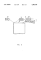
- FIG. 2 shows a multifilm with exaggerated dimensions and a thick outer film.
- FIG. 3 is a block diagram of apparatus according to this invention for controlling the reflectivity of an anti-reflective coating.
- a plurality of films 10 of interleaved low and high index of refraction material for example silica and titania, if the thicknesses of the layers of the multifilm structure are correct, may by this invention be made completely anti-reflective. Practically, however, when the films are fabricated on their substrate, available manufacturing tolerances when depositing the films produce films that are not exactly the correct thickness to cause the structure to be anti-reflective. To modify them to be more anti-reflective, a portion of the outer film must be removed, perhaps by chemical etching or milling. This milling of the outer layer can sometimes correct for errors in both the outer layer and the inner layer thicknesses.
- the reflectivity of the multifilm is extremely sensitive to the thickness of the material with the higher index of refraction, titania.
- the reflectivity of the multifilm is not so sensitive to the thickness of the material with the lower index of refraction, silica.
- An almost perfect anti-reflective multifilm may be fabricated on SF-57 using only two films, an inner film of high index of refraction material and an outer film of low index of refraction material. The outer film is then etched to a critical thickness that causes the multifilm to become almost completely anti-reflective.
- the laser beams 14 travel in both directions through a Faraday Cell 16. It is essential that the arriving beams do not reflect, for such reflection introduces optical loss. Optical loss produces enhanced angular noise in the ring laser gyro output signal, thereby reducing navigation system alignment accuracy.
- the anti-reflective coating of this invention operates equally well for both p and s polarizations.
- an anti-reflective surface film is typically optimum for neither p nor s beams, but they are almost optimum for both polarizations with a difference in reflectivity on the order of only ten parts per million for angles of incoming light beams within ten degrees of normal to the surface of the film.
- the absorptive loss index, k has been neglected in computing the reflectivity, R. k ⁇ 1 for the usual titania and silica films, and thus its inclusion in the equations does not significantly affect the design of the anti-reflective multifilms.
- n the real part of the index of refraction
- ⁇ is the vacuum wavelength of the beam
- n i is the index of refraction of the film
- n o is the index of refraction of the contiguous medium
- ⁇ o is the angle of incidence of the beams in that medium
- t is the thickness in optical phase units of pi over 2.
- Equation (2) determines the film index of refraction for perfect anti-reflection of an s polarized beam.
- Equation (3) is for a p polarized beam.
- both the real and imaginary parts of the complex reflection coefficient cannot become zero at the same time, for a non-zero angle of incidence for any substrate for both s and p polarizations.
- the substrate may be made anti-reflective to the s beam but not the p beam.
- it may be made anti-reflective to the p beam but not the s beam.
- the required thicknesses t 2 and t 1 are determined from equations (4) and (5).
- the sensitivity of the reflectivity, R, to errors in thickness of the films may be computed. Because the reflectivity is a positive or zero numeral, it is expected that the slope of the reflectivity as a function of film thickness, index of refraction, angle of incidence, beam wavelength, substrate index of refraction, index of refraction of the contiguous medium at the proper film thickness, indices of refraction, angles of incidence, beam wavelengths, substrate index of refraction, and index of the contiguous medium will be zero. Therefore, the reflectivity may be expanded in a Taylor's series, keeping the first and second order terms (see equation (8)).
- t 1 and t 2 are the ideal values of the film thicknesses.
- the t i and t j factors are calculated over all of the factors 1 to m.
- the reflectivity is proportional to the square of the error in thickness so that if the thickness error is reduced by one-half, the reflectivity is reduced by one-quarter.
- the thickness of the outer film that produces a minimum reflectivity is the thickness at which the differential of the reflectivity with respect to the outer film thickness becomes zero.
- the equation for that zero derivative when there are only two films in the multifilm is given at (10).
- SHAV 12 is the number of Angstroms that must be milled from the outer film (1) to correct for a one Angstrom surplus in the thickness of the inner film (2). If the error is negative, one must add to the outer film thickness to reduce the reflectivity. In practical terms, one always fabricates the outer film sufficiently thick that material must always be removed therefrom to adjust the reflectivity according to this invention. Similarly, in a 3-film anti-reflective coating, SHAV 12 is the amount of thickness that must be removed from the outer film to correct for one Angstrom surplus in the thickness of the third film. All of the SHAV functions will be in the form SHAV 1j which is the amount of thickness that must be removed from the outer film to correct for one Angstrom surplus in the thickness of the "jth" film.
- say p polarization After the reflectivity to a first polarization of light, (say p polarization) is reduced to the order of one part per million, both the tolerances to index of refraction and to the reflectivity to the other polarization (say s polarization) are determined.
- TOL 2 should be large, TOL 1 should be small, and SHAV 12 should be large.
- the reflectivity is very low: on the order of fourteen to sixteen parts per million.
- Table 1 is presented for substrate indices of refraction ranging from 1.50 to 2.00. Table 1 was calculated using references and definitions from the book, Born, Max and Wolf, Emil, PRINCIPLES OF OPTICS, 5th Ed., Pergamon Press, London, 1975.
- a reflective surface 16 may have as many as twenty dielectric films.
- An optical apparatus may be designed, for example, to reflect a beam of a particular frequency and to be anti-reflective to all other beams.
- the apparatus may be designed to transmit beams, and an anti-reflective coating is important to prevent reflections from an optical surface.
- the EIL is a concept wherein, for the purpose of designing an anti-reflective surface, a multi-film apparatus may be treated as if it were a two-film apparatus.
- each of a different thickness and index of refraction may be treated as a single low index of refraction outer surface, with only a second or inner film having an equivalent thickness and equivalent index of refraction.
- the equivalent index of refraction may be tailored to make possible an anti-reflective surface with substantially no reflection.
- Southwell in an article entitled, "Coating Design Using Very Thin High- and Low-index Layers", Applied Optics, Vol. 24, No. 4, 15 February 1985, describes the use of an equivalent index of refraction and an equivalent thickness for a multi-film in designing an optical coating.
- Southwell derives equations for the thicknesses and indices of refraction of two films which produce a predetermined equivalent thickness and index of refraction. For a two film coating, Southwell derives that the equivalent index of refraction N equals
- N is the equivalent index of refraction
- t H is the thickness of the film having the higher index of refraction n H
- t L is the thickness of the film having the lower index of refraction n L .
- Southwell then proceeds to use the concept to develop a broadband anti-reflection coating for glass which does not have zero reflectivity at any wavelength.
- the applicant herein uses the concepts of equivalent index of refraction and equivalent thickness of film over a very narrow band of wavelengths, for example a bandwidth typical of a ring laser gyro, to reduce the reflectivity to zero at that bandwidth.
- Table 2 shows the total thickness of the EIL inner layer and the ratio the low index to high index thicknesses therein, for a substrate index of refraction of 1.84, as a function of EIL effective index of refraction.
- the film stack 20 may comprise, for example, a TiO 2 film 22 next to the substrate 24.
- the next film 26 outward from film 22 may be SiO 2 .
- TiO 2 films 28 alternate with SiO 2 films 30.
- the outer layer is made over-thick so it may be milled down to exactly the correct thickness, according to this invention, to create an anti-reflective film.
- a laser beam having the spectrum of the laser wherein the anti-reflective device is to be used, is directed from a laser 50 onto the film 18 in the region where the film 18 is being milled.
- the reflected laser beam enters the sensor 52 to produce an electrical signal. That signal is compared in a servo 54 to a zero signal, and the error signal is delivered to the milling equipment 56 to control such milling equipment.
- n H is exactly right for anti-reflection, the combination is not useful.
- the n H material is used alone as layer 2.
- the servo 54 directs the milling equipment to mill the surface 18 until a condition of no or minimum signal appears at the output of the sensor 52.
- the sensor 52 and the servo 54 may, if desired, stop the milling equipment 56 before the signal reaches zero but after it drops below a predetermined value.
- the servo 54 may also, if desired, change the milling speed as the zero signal is approached.
Abstract
A method for producing a narrow band anti-reflective film on a substrate, and the film produced by that method. The improved method being the concept of trimming the outer layer in order to correct for its thickness layers as well as those of the inner layer.
Description
This is a continuation of application Ser. No. 07/530,675 filed May 30, 1990, abandoned, which is a Continuation-In-Part (CIP) of Ser. No. 07/183,569 filed Apr. 19, 1988, now U.S. Pat. No. 4,966,437.
In the field of electro-optics, a non-reflective coating is frequently needed. Such coating should, preferably, be completely non-reflecting to an arriving beam.
To reduce mode coupling and resonator losses in ring laser gyros having intracavity elements such as Faraday Rotators, it is necessary to reduce reflections from such elements, and preferably to reduce reflections to zero. In designing an anti-reflective coating, one might specify both substrate and dielectric film materials having certain required indices of refraction, and such materials might be unavailable. In the real world there are very few low-loss coating materials and even fewer materials that are also sufficiently stable in the environment of a ring laser gyro.
In a multisensor, for example, the Faraday Cell may be fabricated of SF-57, a Schott glass with a high Verdet constant. A non-reflective or anti-reflective coating is deposited on the surfaces of the Faraday Cell.
A typical anti-reflective coating on the Faraday Cell, to prevent reflections of laser beams back into the ring laser, may be a multifilm dielectric of silica, SiO2, and titania, TiO2. The reflectivity of the multifilm coating depends upon the thicknesses and the relative thicknesses of the two films. For a general discussion of the reflectivity of multifilms, see, "Principles of Optics," fifth edition, by Max Born and Emil Wolf, Pergamon Press, 1975, pages 59 et. seq.
A plurality of films of interleaved low and high index of refraction materials such as the silica and titania pair, particularly if the total thickness of the multifilm structure is kept below a predetermined value, may be made completely anti-reflective. Practically, however, when the films are fabricated on their substrate, the films are not exactly the correct thickness to cause the structure to be anti-reflective. To make them anti-reflective, a portion of the outer film must be removed, perhaps by chemical etching or milling.
Other combinations, for example, alumina and titania, alumina and hafnia, silica and hafnia, and silica and tantala may be used.
The reflectivity of the multifilm is extremely sensitive to the thickness of the material with the higher index of refraction. The reflectivity of the multifilm is not so sensitive to the thickness of the material with the lower index of refraction. An almost perfect anti-reflective multifilm may be fabricated on SF-57 using only two films, an inner film of titania and an outer film of silica. The silica is then etched to a critical thickness that causes the multifilm to become almost completely anti-reflective.
It is therefore a feature and an object of this invention to provide means and method for making an anti-reflective coating using materials having a limited range of refractive indices.
It is another object of this invention to provide means and method for making such an anti-reflective surface suitable for use in a ring laser gyro.
Other objects will become apparent from the following description, taken together with the accompanying drawings.
FIG. 1 is a schematic drawing of a ring laser multisensor showing a Faraday Cell positioned therein and having anti-reflective coatings thereon.
FIG. 2 shows a multifilm with exaggerated dimensions and a thick outer film.
FIG. 3 is a block diagram of apparatus according to this invention for controlling the reflectivity of an anti-reflective coating.
A plurality of films 10 of interleaved low and high index of refraction material, for example silica and titania, if the thicknesses of the layers of the multifilm structure are correct, may by this invention be made completely anti-reflective. Practically, however, when the films are fabricated on their substrate, available manufacturing tolerances when depositing the films produce films that are not exactly the correct thickness to cause the structure to be anti-reflective. To modify them to be more anti-reflective, a portion of the outer film must be removed, perhaps by chemical etching or milling. This milling of the outer layer can sometimes correct for errors in both the outer layer and the inner layer thicknesses.
The reflectivity of the multifilm is extremely sensitive to the thickness of the material with the higher index of refraction, titania. The reflectivity of the multifilm is not so sensitive to the thickness of the material with the lower index of refraction, silica. An almost perfect anti-reflective multifilm may be fabricated on SF-57 using only two films, an inner film of high index of refraction material and an outer film of low index of refraction material. The outer film is then etched to a critical thickness that causes the multifilm to become almost completely anti-reflective.
In a multisensor the laser beams 14 travel in both directions through a Faraday Cell 16. It is essential that the arriving beams do not reflect, for such reflection introduces optical loss. Optical loss produces enhanced angular noise in the ring laser gyro output signal, thereby reducing navigation system alignment accuracy.
If the incidence angle on the intracavity element is less than ten degrees, the effect of differences of polarization on the performance of the anti-reflection coating is minimal. Thus, in ring laser gyro apparatus, the anti-reflective coating of this invention operates equally well for both p and s polarizations.
The design of an anti-reflective surface film is typically optimum for neither p nor s beams, but they are almost optimum for both polarizations with a difference in reflectivity on the order of only ten parts per million for angles of incoming light beams within ten degrees of normal to the surface of the film.
In the following calculations, the absorptive loss index, k, has been neglected in computing the reflectivity, R. k<<1 for the usual titania and silica films, and thus its inclusion in the equations does not significantly affect the design of the anti-reflective multifilms. However, if k has a value that is as large as 2% of the real part of the index of refraction, n, k must be considered in calculating the anti-reflective coating film thicknesses.
It has been found that film thickness errors in the range of +/-0.05 optical radians, from the designed thickness for perfect anti-reflection, produce less than 250 parts per million reflection loss. The reasons for stating the film thickness in radians of phase shift instead of Angstroms is that the radian measure is independent of wavelength for a given set of indices of refraction. The physical thickness, ti, of the "ith" film in Angstroms is,
t.sub.i =t λ/{2π[(n.sub.i.sup.2 -n.sub.o.sup.2 sin.sup.2 (θ.sub.o)].sup.1/2) (1)
where λ is the vacuum wavelength of the beam, ni is the index of refraction of the film, no is the index of refraction of the contiguous medium, θo is the angle of incidence of the beams in that medium, and t is the thickness in optical phase units of pi over 2.
It is instructive to design a single anti-reflective film which would be useful if a material of the proper index of refraction were available. Equation (2) determines the film index of refraction for perfect anti-reflection of an s polarized beam. Equation (3) is for a p polarized beam.
n.sub.1s =[n.sub.o.sup.2 sin.sup.2 θ.sub.o +n.sub.o n.sub.s cos(θ.sub.o)cos(θ.sub.s)].sup.1/2 (2)
for s polarization, ##EQU1## for p polarization, and where the subscripts o and s refer to the parameters of the contiguous medium and the substrate, respectively, and where θo and θs are the propagation angles relative to the normal of the interface and no and ns are the indices of refraction.
In general, materials with the correct index of refraction to satisfy equations (2) and (3) are not available.
When two films of different indices of refraction are used, both the real and imaginary parts of the complex reflection coefficient cannot become zero at the same time, for a non-zero angle of incidence for any substrate for both s and p polarizations. For example, the substrate may be made anti-reflective to the s beam but not the p beam. Alternatively it may be made anti-reflective to the p beam but not the s beam. The required thicknesses t2 and t1 are determined from equations (4) and (5).
t.sub.2 =tan.sup.-1 {[(p.sub.o -p.sub.s)(p.sub.1.sup.2 -p.sub.o p.sub.s)p.sub.2.sup.2 ]/[(p.sub.2.sup.2 p.sub.o -p.sub.1.sup.2 p.sub.s)*(p.sub.s p.sub.o -p.sub.2.sup.2)]}.sup.1/2 (4)
t.sub.1 =tan.sup.-1 {tan(t.sub.2)p.sub.1 (p.sub.s p.sub.0 -p.sub.2.sup.2)]/[p.sub.2 (p.sub.1.sup.2 -p.sub.o p.sub.s)]}(5)
where
p.sub.i =n.sub.i cos(θ.sub.i) (s polarized) for i=1,2(6)
and
p.sub.i =cos(θ.sub.i)/n.sub.i (p polarized) for i=1,2(7)
and the numerical subscripts refer to the film parameters with the lowest number referring to the film closest to the contiguous medium.
Note that the requirement for zero reflectivity of both the p an the s polarized beams are not simultaneously satisfied by two films. To design an anti-reflective multifilm for circularly polarized light, one designs such multifilms for both s and p polarization and averages the film thicknesses between those required for s polarization and those required for p polarization. For incidence angles of less than ten degrees, both p and s polarizations will have nearly zero reflection.
The sensitivity of the reflectivity, R, to errors in thickness of the films may be computed. Because the reflectivity is a positive or zero numeral, it is expected that the slope of the reflectivity as a function of film thickness, index of refraction, angle of incidence, beam wavelength, substrate index of refraction, index of refraction of the contiguous medium at the proper film thickness, indices of refraction, angles of incidence, beam wavelengths, substrate index of refraction, and index of the contiguous medium will be zero. Therefore, the reflectivity may be expanded in a Taylor's series, keeping the first and second order terms (see equation (8)). ##EQU2## where the sum is taken over the range, i=1,2 and j=1,2 and the second derivative factor is evaluated at the designed thicknesses of the films, t1 and t2. t1o and t2o are the ideal values of the film thicknesses. When there are more than two films, namely m films, in a multifilm, the ti and tj factors are calculated over all of the factors 1 to m.
In a typical situation, only a few of the thicknesses will be in error. To determine the thickness error permitted to obtain 1000 parts per million reflectivity when only one of the actual thicknesses differs from its designed thickness, one substitutes numerals into equation (8) and takes the partial derivative with respect to that particular thickness, using equation (9).
t.sub.i ={0.002/[δ.sup.2 R/δt.sub.i.sup.2 ]}.sup.1/2(9)
Note from equation (8) that the reflectivity is proportional to the square of the error in thickness so that if the thickness error is reduced by one-half, the reflectivity is reduced by one-quarter.
To determine the correction needed in the outer film to reduce the reflectivity caused by an error in thickness of an inner film, one must examine the mixed partial second derivative terms of equation (8). The thickness of the outer film that produces a minimum reflectivity is the thickness at which the differential of the reflectivity with respect to the outer film thickness becomes zero. The equation for that zero derivative when there are only two films in the multifilm is given at (10).
dR/dt.sub.1 =(δ.sup.2 R/δt.sub.1.sup.2)(t.sub.1 -t.sub.10)+δ.sup.2 R/δt.sub.1 δt.sub.2)(t.sub.2 -t.sub.o)=0 (10)
The second derivatives are evaluated at the (t1o,t2o) coordinates where R=0. Solving, the equation for (t1 -t1o) produces
(t.sub.1 -t.sub.1o)=-[(δ.sup.2 R/δt.sub.1 δt.sub.2)/(δ.sup.2 R/δt.sub.1.sup.2)](t.sub.2 -t.sub.2o).(11)
in radians which can be converted to Angstroms. The coefficient on the right side of the equation (11) is called herein SHAV12 which is the number of Angstroms that must be milled from the outer film (1) to correct for a one Angstrom surplus in the thickness of the inner film (2). If the error is negative, one must add to the outer film thickness to reduce the reflectivity. In practical terms, one always fabricates the outer film sufficiently thick that material must always be removed therefrom to adjust the reflectivity according to this invention. Similarly, in a 3-film anti-reflective coating, SHAV12 is the amount of thickness that must be removed from the outer film to correct for one Angstrom surplus in the thickness of the third film. All of the SHAV functions will be in the form SHAV1j which is the amount of thickness that must be removed from the outer film to correct for one Angstrom surplus in the thickness of the "jth" film.
It is informative to consider the design of a three film multifilm. If the geometric mean of the indices of refraction of the materials in the multifilm is higher than the index of refraction of the substrate, it is important in the multifilm to place the film having the highest index of refraction next to the substrate and to use a film having the lowest index of refraction as the outer film 18.
To design a threefilm, two material, multifilm to produce a reflectivity less than 200 parts per million, one determines the first and second derivatives of reflectivity with respect to thickness of the films. One then substitutes the assumed thicknesses into the equations and, using the first derivatives of reflectivity with respect to thickness as constants, the following equations (12), (13), and (14) are solved simultaneously to obtain the correction to be made to the assumed thicknesses of films 1, 2, and 3. ##EQU3## where "tio " are the design values of the "ti "s to reduce the reflectivity from its value at the manufactured thicknesses to zero.
The equations (12) , (13) and (14) are solved simultaneously for
Δt.sub.i =t.sub.i -t.sub.i o. (15)
to obtain a new set of t1, t2, t3 which give lower reflectivity than t1o, t2o, t3o. They are used in the numerical design process wherein SHAV13 and SHAV12 are defined the same as for the two film SHAV12, and the values for ti can be corrected using the equations
t.sub.io =t.sub.i -Δt.sub.i. (16)
By repeated iterations, zero reflectivity is approached.
After the reflectivity to a first polarization of light, (say p polarization) is reduced to the order of one part per million, both the tolerances to index of refraction and to the reflectivity to the other polarization (say s polarization) are determined.
To obtain a formula for an estimate of the reflectivity, when the actual errors in thicknesses and indices of refraction are known, one expands the reflectivity, R, in a Taylor series about zero.
R=(δ.sup.2 R/δt.sub.1 δt.sub.2)+Δt.sub.1 Δt.sub.2 +(δ.sup.2 R/δt.sub.1.sup.2)(Δt.sub.1.sup.2 /2)+(δ.sup.2 R/δt.sub.2.sup.2)(Δt.sub.2.sup.2 /2) (17)
To determine the sensitivity of the reflectivity to a small change, Δt1 in t1, take the derivative of R in equation (17) with respect to Δt1
dR/d(Δt.sub.1)=(δ.sup.2 R/δt.sub.1 δt.sub.2)Δt.sub.2 +(δ.sup.2 R/δt.sub.1.sup.2)Δt.sub.1. (18)
to determine the required thickness change of t1 for a minimum R, set equation (18) equal to zero, and solve for Δt1.
t.sub.1Rmin =-((.sup.δ2 R/Δt.sub.1 δt.sub.2)/(δ.sup.2 R/δt.sub.1.sup.2)}Δt.sub.2(19)
But the portion of equation (19) within the braces {} is identically equal to SHAV12', and
t.sub.1Rmin =-SHAV.sub.12 Δt.sub.2 (20)
Rewriting equations (17) and (19 to simplify algebraic manipulation,
R=AΔt.sub.1 Δt.sub.2 +BΔt.sub.1.sup.2 /2+CΔt.sub.2.sup.2 /2 (17A)
and
t.sub.1Rmin =-(A/B)Δt.sub.2 =-SHAV.sub.12 t.sub.2 (19A)
Substituting equation (19A) into equation (17A),
R=-(A.sup.2 /B)Δt.sub.2.sup.2 +(BA.sup.2 /2B.sup.2)Δt.sub.2.sup.2 +(C/2) Δt.sub.2.sup.2(17B)
Cancelling and factoring,
R=(Δt.sub.2.sup.2 /2){-2B(A.sup.2 /B.sup.2)+(B)(A.sup.2 /B.sup.2)+C}(17C)
R=(Δt.sub.2.sup.2 /2){(-B(A.sup.2 /B.sup.2)+C} (17D)
R=(Δt.sub.2.sup.2 /2){C-SHAV.sub.12.sup.2 B} (17E)
or
R.sub.min ={(δ.sup.2 R/δt.sub.2.sup.2)-SHAV.sub.12.sup.2 (δ.sup.2 R/δt.sub.1.sup.2)}(Δt.sub.2.sup.2 /2)(21)
Definition of tolerance, "TOL":
For a given amount of allowed reflectivity error, Rj, due to just one film thickness error, from equation (17), the thickness tolerance for Rj is
t.sub.j ={2ΔR.sub.j /[δ.sup.2 R/δt.sub.j.sup.2 ]}.sup.1/2.(22)
In ts table 1, ΔR is chosen as ΔRj =0.001 and the +/- values are the thickness tolerances corresponding to
Rj =0.0001.
TOL.sub.2 ={0.002/δ.sup.2 R/δt.sub.2.sup.2 }.sup.1/2 (in Angstroms) (23A)
and
TOL.sub.1 =0.002/δ.sup.2 R/δt.sub.1.sup.2 }.sup.1/2 (in Angstroms) (23B)
Factoring δ2 R/δt2 2 from equation 21,
R.sub.min =(δ.sup.2 R/δt.sub.2.sup.2){1-SHAV.sub.12.sup.2 *[ (δ.sup.2 R/δt.sub.1.sup.2)/(δ.sup.2 R/δt.sub.2.sup.2)]}(Δt.sub.2.sup.2 /2) (24)
Substituting TOL1 AND TOL2 into the equation (24),
R.sub.min ={Δt.sub.2.sup.2 /TOL.sub.2.sup.2 *{1-[SHAV.sub.12.sup.2 TOL.sub.2.sup.2 /TOL.sub.1.sup.2 ]}*(1000) in ppm./(Angstrom).sup.2.(24A)
To design a two film anti-reflective apparatus, then, TOL2 should be large, TOL1 should be small, and SHAV12 should be large.
For a typical inner film of Tio2, n2 =2.30+/-0.11, and an outer film of Sio2, n1 =1.48+/-0.05, for various thicknesses, calculated as recited above, the reflectivity is very low: on the order of fourteen to sixteen parts per million.
The following Table 1 is presented for substrate indices of refraction ranging from 1.50 to 2.00. Table 1 was calculated using references and definitions from the book, Born, Max and Wolf, Emil, PRINCIPLES OF OPTICS, 5th Ed., Pergamon Press, London, 1975.
Equation (24B) is a sample calculation wherein n1 =nL =1.48, n2 =nH =2.30, SHAV12 =0.25, TOL1 =52 Angstroms, TOL2=61 Angstroms, and n=1.84.
R.sub.min /(Angstrom).sup.2 =(1000)(1/61.sup.2){1-[(0.05)(61/52)].sup.2 }=0.27 ppm/(Angstrom).sup.2 (24B)
              TABLE 1
______________________________________
silica n.sub.L = 1.48 = n.sub.1   titania n.sub.H = 2.30 = n.sub.2
                        THICKNESS
           THICKNESS OF INNER FILM
SUBSTRATE  OUTER FILM   NUMBER
INDEX OF   NUMBER ONE   TWO
REFRACTION +/- TOL.sub.1
                        +/- TOL     SHAV.sub.12
______________________________________
1.50       1441 +/- 52  200 +/- 31  0.49
1.52       1429 +/- 52  204 +/- 32  0.45
1.54       1416 +/- 52  207 +/- 33  0.42
1.56       1404 +/- 52  210 +/- 34  0.38
1.58       1393 +/- 52  213 +/- 36  0.35
1.60       1381 +/- 52  215 +/- 37  0.32
1.62       1370 +/- 52  218 +/- 38  0.29
1.64       1359 +/- 52  221 +/- 40  0.26
1.66       1348 +/- 52  223 +/- 41  0.24
1.68       1337 +/- 52  225 +/- 43  0.21
1.70       1327 +/- 52  227 +/- 45  0.19
1.72       1317 +/- 52  229 +/- 47  0.17
1.74       1307 +/- 52  231 +/- 49  0.14
1.76       1297 +/- 52  233 +/- 51  0.12
1.78       1287 +/- 52  234 +/- 53  0.11
1.80       1277 +/- 52  235 +/- 56  0.09
1.82       1268 +/- 52  236 +/- 58  0.07
1.84       1258 +/- 52  237 +/- 61  0.05
1.86       1249 +/- 52  238 +/- 64  0.04
1.88       1240 +/- 52  238 +/- 68  0.02
1.90       1231 +/- 52  238 +/- 72  0.01
1.92       1222 +/- 52  238 +/- 76  0.00
1.94       1213 +/- 52  237 +/- 80  0.01
1.96       1204 +/- 52  236 +/- 86  0.02
1.98       1195 +/- 52  235 +/- 92  0.03
2.00       1187 +/- 52  231 +/- 98  0.04
______________________________________
By changing n2 to n2 =2.05, for a substrate index of refraction of 1.84, we get SHAV12 =0.28, TOL1 =52, TOL2 =142, the reflectivity per (Angstrom)2 of t2 error may further be reduced to the calculation of equation (24C). ##EQU4##
But a material having an index of refraction equal to 2.05 is not readily available. Thus, according to this invention, a concept of an effective index layer, hereinafter called "EIL" is introduced. A reflective surface 16 may have as many as twenty dielectric films. An optical apparatus may be designed, for example, to reflect a beam of a particular frequency and to be anti-reflective to all other beams. The apparatus may be designed to transmit beams, and an anti-reflective coating is important to prevent reflections from an optical surface. The EIL is a concept wherein, for the purpose of designing an anti-reflective surface, a multi-film apparatus may be treated as if it were a two-film apparatus. The combination of multiple films, each of a different thickness and index of refraction, may be treated as a single low index of refraction outer surface, with only a second or inner film having an equivalent thickness and equivalent index of refraction. Thus, the equivalent index of refraction may be tailored to make possible an anti-reflective surface with substantially no reflection.
William H. Southwell, in an article entitled, "Coating Design Using Very Thin High- and Low-index Layers", Applied Optics, Vol. 24, No. 4, 15 February 1985, describes the use of an equivalent index of refraction and an equivalent thickness for a multi-film in designing an optical coating. Southwell derives equations for the thicknesses and indices of refraction of two films which produce a predetermined equivalent thickness and index of refraction. For a two film coating, Southwell derives that the equivalent index of refraction N equals
N{(n.sub.H.sup.2 t.sub.H n.sub.L.sup.2 t.sub.L)/(t.sub.H +t.sub.L)}.sup.1/2,(25)
factoring nH from the numerator and denominator and cancelling, and defining a new factor, r=tL /tH, then
N={(n.sub.H.sup.2 +rn.sub.L.sup.2)/(1+r)}.sup.1/2 (25A)
and
T.sub.L =T-t.sub.H.sup.3 (26)
where N is the equivalent index of refraction, wherein tH is the thickness of the film having the higher index of refraction nH, and tL is the thickness of the film having the lower index of refraction nL.
Southwell then proceeds to use the concept to develop a broadband anti-reflection coating for glass which does not have zero reflectivity at any wavelength.
The applicant herein uses the concepts of equivalent index of refraction and equivalent thickness of film over a very narrow band of wavelengths, for example a bandwidth typical of a ring laser gyro, to reduce the reflectivity to zero at that bandwidth.
Consider, for example, an outer film 18 having an index of refraction n1 =1.48 used with an equivalent inner film (which might be a large number of stacked films) index of refraction, n2 =2.05. n=2.05 was chosen because it produces a very low reflectance when coated in proper thickness. Assume SHAV12 =0.28, TOL1 =52, and TOL2 -142. Then the minimum reflectivity per (Angstrom)2 is shown in equation (24C). Present well known materials can be stacked to obtain any desired n between the lower and higher indices of refraction, n1 and n2. For Tio2 and Sio2 the range is 1.48 to 2.30.
The use of very thin films in a multifilm, instead of high index of refraction inner film produces an anti-reflective coat that is very tolerant to its overall thickness error. For example, when the substrate is SF57, and when only two materials, a high index and a low index of refraction material are alternated in a multifilm with the outside film of the lower index of refraction material, the ratio of the thicknesses of the high index of refraction films, tH, to the thicknesses of the low index of refraction films, tL, in the computation of the EIL is not very critical.
It is instructive to compare anti-reflective film calculations wherein the outer film index of refraction is 1.48.
For silica and titania, Table 2 shows the total thickness of the EIL inner layer and the ratio the low index to high index thicknesses therein, for a substrate index of refraction of 1.84, as a function of EIL effective index of refraction.
              TABLE 2
______________________________________
For silica and titania
t.sub.L /t.sub.H = r
THICKNESS       EIL INDEX OF EIL
ANGSTROMS       REFRACTION   T
______________________________________
0.00            2.30         240
0.02            2.29         245
0.03            2.28         250
0.05            2.27         256
0.06            2.26         262
0.08            2.25         268
0.10            2.24         275
0.11            2.23         282
0.13            2.22         290
0.15            2.21         296
0.17            2.20         304
0.19            2.19         312
0.21            2.18         321
0.23            2.17         331
0.25            2.16         341
0.27            2.15         352
0.30            2.14         363
0.32            2.13         375
0.35            2.12         388
0.37            2.11         403
0.40            2.10         418
0.42            2.09         435
0.45            2.08         455
0.48            2.07         476
0.51            2.06         500
0.54            2.05         528
0.57            2.04         560
0.60            2.03         601
0.64            2.02         658
______________________________________
As shown in FIG. 2, the film stack 20 may comprise, for example, a TiO2 film 22 next to the substrate 24. The next film 26 outward from film 22 may be SiO2. TiO2 films 28 alternate with SiO2 films 30. The outer layer is made over-thick so it may be milled down to exactly the correct thickness, according to this invention, to create an anti-reflective film.
A laser beam, having the spectrum of the laser wherein the anti-reflective device is to be used, is directed from a laser 50 onto the film 18 in the region where the film 18 is being milled. The reflected laser beam enters the sensor 52 to produce an electrical signal. That signal is compared in a servo 54 to a zero signal, and the error signal is delivered to the milling equipment 56 to control such milling equipment.
Other material combinations may be used, and the following tables demonstrate some of the variations.
              TABLE 1A
______________________________________
n.sub.H = 2.20 (Ta.sub.2 O.sub.5, HfO.sub.2)  n.sub.1 = n.sub.L = 1.48
(SiO.sub.2)
                        THICKNESS
           THICKNESS OF INNER FILM
SUBSTRATE  OUTER FILM   NUMBER
INDEX OF   NUMBER ONE   TWO
REFRACTION +/- TOL.sub.1
                        +/- TOL     SHAV.sub.12
______________________________________
1.40       1493 +/- 52  214 +/- 31  1.01
1.42       1479 +/- 52  219 +/- 32  .95
1.44       1464 +/- 52  224 +/- 33  .89
1.46       1450 +/- 52  228 =/- 34  .83
1.48       1436 +/- 52  233 +/- 35  .78
1.50       1423 +/- 52  237 +/- 37  .73
1.52       1410 +/- 52  242 +/- 38  .68
1.54       1397 +/- 52  246 +/- 39  .68
1.56       1385 +/- 52  250 +/- 41  .58
1.58       1373 +/- 52  254 +/- 43  .54
1.60       1361 +/- 52  259 +/- 44  .50
1.62       1349 +/- 52  262 +/- 46  .46
1.64       1338 +/- 52  266 +/- 48  .43
1.66       1327 +/- 52  270 +/- 50  .39
1.68       1318 +/- 52  274 +/- 53  .36
1.70       1305 +/- 52  277 +/- 55  .33
1.72       1295 +/- 52  281 +/- 58  .30
1.74       1284 +/- 52  284 +/- 61  .28
1.76       1274 +/- 52  288 +/- 64  .25
1.78       1264 +/- 52  291 +/- 67  .23
1.80       1254 +/- 52  294 +/- 71  .20
1.82       1244 +/- 52  298 +/- 75  .18
1.84       1235 +/- 52  301 +/- 80  .16
1.86       1225 +/- 52  304 +/- 85  .15
1.88       1216 +/- 52  307 +/- 91  .13
1.90       1207 +/- 52  309 +/- 98  .11
1.92       1198 +/- 52   312 +/- 105
                                    .10
1.94       1189 +/- 52   315 +/- 114
                                    .09
1.96       1180 +/- 52   317 +/- 124
                                    .07
1.98       1171 +/- 52   319 +/- 136
                                    .06
______________________________________
The corresponding table 2A follows for substrate n=1.84,
              TABLE 2A
______________________________________
t.sub.L /t.sub.H = r
THICKNESS       EIL INDEX OF EIL
ANGSTROMS       REFRACTION   T
______________________________________
0.00            2.20
0.05            2.17
0.10            2.14
0.15            2.12
0.20            2.10
0.25            2.08
0.30            2.06         516
0.35            2.04
0.40            2.02
0.45            2.00
______________________________________
Only tL /tH =0.30 or 0.35 are of interest for anti-reflection where the EIL index of refraction is about 2.05.
              TABLE 1B
______________________________________
n.sub.H = 2.00 (Zr.sub.2 O)  n.sub.L = n.sub.1 = 1.48 (Silica)
                        THICKNESS
SUBSTRATE  THICKNESS OF INNER FILM
INDEX OF   OUTER FILM   NUMBER
REFRACTION NUMBER ONE   TWO         SHAV.sub.12
______________________________________
1.40       1438 +/- 52  317 +/- 43  .85
1.42       1421 +/- 52  326 +/- 46  .80
1.44       1404 +/- 52  336 +/- 47  .76
1.46       1389 +/- 52  346 +/- 49  .72
1.48       1373 +/- 52  355 +/- 52  .68
1.50       1358 +/- 52  365 +/- 52  .65
1.52       1343 +/- 52  376 +/- 52  .61
1.54       1328 +/- 52  386 +/- 52  .58
1.56       1313 +/- 52  397 +/- 52  .55
1.58       1299 +/- 52  408 +/- 66  .53
1.60       1285 +/- 52  420 +/- 70  .50
1.62       1271 +/- 52  433 +/- 74  .48
1.64       1257 +/- 52  446 +/- 78  .46
1.66       1243 +/- 52  460 +/- 84  .43
1.68       1229 +/- 52  476 +/- 90  .42
1.70       1214 +/- 52  493 +/- 97  .40
1.72       1200 +/- 52   513 +/- 104
                                    .38
1.74       1185 +/- 52   536 +/- 113
                                    .37
1.76       1169 +/- 52   563 +/- 123
                                    .35
1.78       1152 +/- 52   597 +/- 135
                                    .34
1.80       1132 +/- 52   645 +/- 150
                                    .33
______________________________________
The corresponding table 2B follows for substrate n=1.84,
              TABLE 2B
______________________________________
t.sub.L /t.sub.H = r
THICKNESS       EIL INDEX OF EIL
ANGSTROMS       REFRACTION   T
______________________________________
0.00            2.00
0.05            1.98
0.10            1.96
0.15            1.94
0.20            1.92
0.25            1.91
0.30            1.89
0.35            1.88
0.40            1.87
0.45            1.85
______________________________________
None of the values of Table 2B are of interest because the EIL index of refraction is too small.
              TABLE 1C
______________________________________
n.sub.H = 2.05 (ZrO.sub.2)  n.sub.1 = n.sub.L - 1.48 (Silica)
                        THICKNESS
           THICKNESS OF INNER FILM
SUBSTRATE  OUTER FILM   NUMBER
INDEX OF   NUMBER ONE   TWO
REFRACTION +/- TOL.sub.1
                        +/- TOL     SHAV.sub.12
______________________________________
1.40       1456 +/- 52  283 +/- 39  .89
1.42       1440 +/- 52  291 +/- 41  .84
1.44       1424 +/- 52  299 +/- 43  .79
1.46       1409 +/- 52  307 +/- 44  .75
1.48       1394 +/- 52  315 +/- 46  .71
1.50       1380 +/- 52  323 +/- 48  .67
1.52       1365 +/- 52  331 +/- 51  .63
1.54       1351 +/- 52  339 +/- 53  .59
1.56       1338 +/- 52  347 +/- 56  .56
1.58       1324 +/- 52  355 +/- 58  .53
1.60       1311 +/- 52  364 +/- 61  .50
1.62       1298 +/- 52  372 +/- 65  .47
1.64       1286 +/- 52  381 +/- 68  .45
1.66       1273 +/- 52  391 +/- 72  .42
1.68       1261 +/- 52  401 +/- 77  .40
1.70       1248 +/- 52  411 +/- 82  .38
1.72       1236 +/- 52  422 +/- 87  .36
1.74       1224 +/- 52  434 +/- 94  .35
1.76       1212 +/- 52   447 +/- 101
                                    .33
1.78       1199 +/- 52   462 +/- 109
                                    .31
1.80       1187 +/- 52   478 +/- 118
                                    .30
1.82       1175 +/- 52   497 +/- 129
                                    .29
1.84       1162 +/- 52   520 +/- 142
                                    .28
1.86       1148 +/- 52   548 +/- 158
                                    .27
1.88       1133 +/- 52   585 +/- 178
                                    .26
1.90       1113 +/- 52   648 +/- 203
                                    .25
______________________________________
The corresponding table 2C follows for substrate n=1.84,
              TABLE 2C
______________________________________
t.sub.L /t.sub.H = r
THICKNESS       EIL INDEX OF EIL
ANGSTROMS       REFRACTION   T
______________________________________
0.00            2.05         516
0.05            2.03
0.10            2.00
0.15            1.98
0.20            1.97
0.25            1.95
0.30            1.93
0.35            1.92
0.40            1.90
0.45            1.89
______________________________________
Because nH is exactly right for anti-reflection, the combination is not useful. The nH material is used alone as layer 2.
              TABLE 1D
______________________________________
n.sub.H = 2.20 (HfO.sub.2, Ta.sub.2 O.sub.5)  n.sub.1 = n.sub.L - 1.65
(Al.sub.2 O.sub.3)
                        THICKNESS
           THICKNESS OF INNER FILM
SUBSTRATE  OUTER FILM   NUMBER
INDEX OF   NUMBER ONE   TWO
REFRACTION +/- TOL.sub.1
                        +/- TOL     SHAV.sub.12
______________________________________
1.40       1302 +/- 36  324 +/- 31  .99
1.42       1287 +/- 36  335 +/- 32  .96
1.44       1272 +/- 36  346 +/- 33  .92
1.46       1257 +/- 36  357 +/- 34  .89
1.48       1243 +/- 36  368 +/- 35  .86
1.50       1229 +/- 36  380 +/- 37  .83
1.52       1215 +/- 36  391 +/- 38  .80
1.54       1201 +/- 36  404 +/- 39  .78
1.56       1187 +/- 36  416 +/- 41  .75
1.58       1173 +/- 36  430 +/- 43  .73
1.60       1159 +/-  36 444 +/- 44  .70
1.62       1145 +/- 36  459 +/- 46  .68
1.64       1130 +/- 36  475 +/- 48  .66
1.66       1115 +/- 36  492 +/- 50  .64
1.68       1100 +/- 36  512 +/- 53  .63
1.70       1083 +/- 36  534 +/- 55  .61
1.72       1065 +/- 36  559 +/- 58  .59
1.74       1044 +/- 36  591 +/- 61  .58
1.76       1012 +/- 36  644 +/- 64  .56
______________________________________
There is no solution for AR coating with ns =1.84 for these indices for nH and nL, and a corresponding table 2D is not presented.
              TABLE 1E
______________________________________
n.sub.H = 2.15 (Ta.sub.2 O.sub.5)  n.sub.1 = nL (Silica)
                        THICKNESS
           THICKNESS OF INNER FILM
SUBSTRATE  OUTER FILM   NUMBER
INDEX OF   NUMBER ONE   TWO
REFRACTION +/- TOL.sub.1
                        +/- TOL     SHAV.sub.12
______________________________________
1.40       1483/- 52    233 +/- 33  .97
1.42       1468 +/- 52  239 +/- 34  .91
1.44       1453 +/- 52  245 +/- 36  .86
1.46       1439 +/- 52  250 +/- 37  .80
1.48       1425 +/- 52  255 +/- 38  .75.
1.50       1411 +/- 52  261 +/- 40  .71
1.52       1398 +/- 52  266 +/- 41  .66
1.54       1385 +/- 52  271 +/- 43  .62
1.56       1372 +/- 52  276 +/- 45  .58
1.58       1360 +/- 52  281 +/- 47  .54
1.60       1348 +/- 52  286 +/- 49  .50
1.62       1336 +/- 52  281 +/- 51  .47
1.64       1324 +/- 52  296 +/- 54  .43
1.66       1313 +/- 52  301 +/- 56  .40
1.68       1302 +/- 52  306 +/- 59  .38
1.70       1290 +/- 52  311 +/- 62  .35
1.72       1280 +/- 52  316 +/- 65  .32
1.74       1269 +/- 52  321 +/- 69  .30
1.76       1258 +/- 52  326 +/- 73  .28
1.78       1248 +/- 52  331 +/- 77  .26
1.80       1238 +/- 52  337 +/- 82  .24
1.82       1228 +/- 52  342 +/- 88  .22
1.84       1218 +/- 52  347 +/- 94  .20
1.86       1208 +/- 52   353 +/- 101
                                    .19
1.88       1198 +/- 52   359 +/- 109
                                    .17
1.90       1189 +/- 52   366 +/- 119
                                    .16
1.92       1180 +/- 52   372 +/- 130
                                    .15
1.94       1170 +/- 52   380 +/-  143
                                    .14
1.96       1161 +/- 52   388 +/- 159
                                    .13
1.98       1152 +/- 52   398 +/- 179
                                    .12
______________________________________
The corresponding table 2E follows for substrate n=1.84,
              TABLE 2E
______________________________________
t.sub.L /t.sub.H = r
THICKNESS       EIL INDEX OF EIL
ANGSTROMS       REFRACTION   T
______________________________________
0.00            2.15
0.05            2.12
0.10            2.10
0.15            2.08
0.20            2.05         516
0.25            2.03
0.30            2.02
0.35            2.00
0.40            1.98
0.45            1.97
______________________________________
tL /tH =0.20 is of interest because the EIL index of refraction is 2.05 which is correct for high tolerance anti-reflection
              TABLE 1F
______________________________________
n.sub.H = 2.25 (HfO.sub.2)  n.sub.1 = n.sub.L = 1.48 (Silica)
                        THICKNESS
           THICKNESS OF INNER FILM
SUBSTRATE  OUTER FILM   NUMBER
INDEX OF   NUMBER ONE   TWO
REFRACTION +/- TOL.sub.1
                        +/- TOL     SHAV.sub.12
______________________________________
1.40       1502 +/- 52  197 +/- 28  1.06
1.42       1488 +/- 52  201 +/- 29  .89
1.44       1473 +/- 52  206 +/- 30  .92
1.46       1460 +/- 52  210 +/- 31  .86
1.48       1446 +/- 52  214 +/- 32  .80
1.50       1433 +/- 52  218 +/- 34  .75
1.52       1420 +/- 52  221 +/- 35  .69
1.54       1408 +/- 52  225 +/- 36  .64
1.56       1396 +/- 52  229 +/- 37  .59
1.58       1384 +/- 52  232 +/- 39  .55
1.60       1372 +/- 52  235 +/- 40  .50
1.62       1361 +/- 52  238 +/- 42  .46
1.64       1350 +/- 52  242 +/- 44  .42
1.66       1339 +/- 52  244 +/- 45  .38
1.68       1328 +/- 52  247 +/- 47  .35
1.70       1317 +/- 52  250 +/- 49  .31
1.72       1307 +/- 52  253 +/- 52  .28
1.74       1297 +/- 52  255 +/- 54  .25
1.76       1287 +/- 52  257 +/- 57  .22
1.78       1277 +/- 52  260 +/- 59  .20
1.80       1267 +/- 52  262 +/- 62  .17
1.82       1257 +/- 52  284 +/- 66  .15
1.84       1248 +/- 52  265 +/- 69  .12
1.86       1239 +/- 52  267 +/- 73  .10
1.88       1229 +/- 52  268 +/- 78  .08
1.90       1220 +/- 52  269 +/- 83  .07
1.92       1211 +/- 52  270 +/- 88  .05
1.94       1202 +/- 52  270 +/-  95 .03
1.96       1194 +/- 52   270 +/- 102
                                    .02
1.98       1185 +/- 52   269 +/- 110
                                    .01
______________________________________
The corresponding table 2F follows for substrate n=1.84,
              TABLE 2F
______________________________________
t.sub.L /t.sub.H = r
THICKNESS       EIL INDEX OF EIL
ANGSTROMS       REFRACTION   T
______________________________________
0.00            2.25
0.05            2.22
0.10            2.19
0.15            2.16
0.20            2.14
0.25            2.12
0.30            2.10
0.35            2.08
0.40            2.06         516
0.45            2.04
______________________________________
tL /tH =0.40 is of interest because the EIL index of refraction is 2.06 which is almost the correct 2.05 value for anti-reflection.
              TABLE 1G
______________________________________
n.sub.H = 2.10 (ZrO.sub.2, Ta.sub.2 O.sub.5)  n.sub.1 = n.sub.L = 1.65
(Al.sub.2 O.sub.3)
                        THICKNESS
           THICKNESS OF INNER FILM
SUBSTRATE  OUTER FILM   NUMBER
INDEX OF   NUMBER ONE   TWO
REFRACTION +/- TOL.sub.1
                        +/- TOL     SHAV.sub.12
______________________________________
1.40       1249 +/- 36  410 +/- 36  .90
1.42       1231 +/- 36  426 +/- 37  .87
1.44       1213 +/- 36  443 +/- 39  .84
1.46       1195 +/- 36  461 +/- 40  .81
1.48       1176 +/- 36  479 +/- 42  .78
1.50       1157 +/- 36  500 +/- 44  .76
1.52       1137 +/- 36  522 +/- 46  .74
1.54       1117 +/- 36  546 +/- 48  .72
1.56       1094 +/- 36  574 +/- 50  .69
1.58       1068 +/- 36  608 +/- 52  .68
1.60       1034 +/-  36 658 +/- 55  .66
______________________________________
There is no solution for AR coating with ns =1.84 for the indices for nH and nL, and a corresponding table 2G is not presented.
              TABLE 1H
______________________________________
n.sub.H = 2.10 (ZrO.sub.2, Ta.sub.2 O.sub.5)  n.sub.1 = n.sub.L = 1.48
(Silica)
                        THICKNESS
           THICKNESS OF INNER FILM
SUBSTRATE  OUTER FILM   NUMBER
INDEX OF   NUMBER ONE   TWO
REFRACTION +/- TOL.sub.1
                        +/- TOL     SHAV.sub.12
______________________________________
1.40       1471 +/- 52  266 +/- 36  .93
1.42       1455 +/- 52  263 +/- 37  .87
1.44       1440 +/- 52  269 +/- 39  .82
1.46       1425 +/- 52  276 +/- 40  .77
1.48       1411 +/- 52  282 +/- 42  .73
1.50       1397 +/- 52  289 +/- 44  .69
1.52       1383 +/- 52  295 +/- 46  .64
1.54       1370 +/- 52  301 +/- 48  .61
1.56       1357 +/- 52  308 +/- 50  .57
1.58       1344 +/- 52  314 +/- 52  .53
1.60       1332 +/- 52  321 +/-  52 .50
1.62       1310 +/- 52  327 +/- 52  .47
1.64       1307 +/- 52  334 +/- 60  .44
1.66       1295 +/- 52  340 +/- 63  .41
1.68       1284 +/- 52  347 +/- 67  .39
1.70       1272 +/- 52  354 +/- 71  .37
1.72       1261 +/- 52  361 +/- 75  .34
1.74       1250 +/- 52  369 +/- 80  .32
1.75       1239 +/- 52  377 +/- 85  .30
1.78       1228 +/- 52  385 +/- 91  .29
1.80       1217 +/- 52  394 +/- 97  .27
1.82       1206 +/- 52   403 +/- 105
                                    .25
1.84       1196 +/- 52   413 +/- 114
                                    .24
1.86       1185 +/- 52   425 +/- 124
                                    .23
1.88       1174 +/- 52   437 +/- 136
                                    .22
1.90       1164 +/- 52   452 +/- 150
                                    .21
1.92       1153 +/- 52   470 +/- 168
                                    .20
1.94       1142 +/- 52   491 +/- 190
                                    .19
1.96       1130 +/- 52   520 +/- 218
                                    .18
1.98       1117 +/- 52   561 +/- 256
                                    .18
______________________________________
The corresponding table 2H follows for substrate n=1.84,
              TABLE 2H
______________________________________
t.sub.L /t.sub.H = r
THICKNESS       EIL INDEX OF EIL
ANGSTROMS       REFRACTION   T
______________________________________
0.00            2.10
0.05            2.08
0.10            2.05         516
0.15            2.03
0.20            2.01
0.25            1.99
0.30            1.97
0.35            1.96
0.40            1.94
0.45            1.93
______________________________________
tL /tH =0.10 is of interest because the EIL index of refraction is 2.05 which is correct for anti-reflection.
              TABLE 1J
______________________________________
n.sub.H = 2.30 (TiO.sub.2)  n.sub.1 = n.sub.L = 1.65 (Al.sub.2 O.sub.3)
                        THICKNESS
           THICKNESS OF INNER FILM
SUBSTRATE  OUTER FILM   NUMBER
INDEX OF   NUMBER ONE   TWO
REFRACTION +/- TOL.sub.1
                        +/- TOL     SHAV.sub.12
______________________________________
1.40       1335 +/- 36  268 +/- 26  1.09
1.42       1322 +/- 36  276 +/- 27  1.05
1.44       1308 +/- 36  284 +/- 28  1.01
1.46       1295 +/- 36  292 +/- 29  .97
1.48       1283 +/- 36  300 +/- 30  .94
1.50       1270 +/- 36  308 +/- 31  .90
1.52       1268 +/- 36  316 +/- 32  .87
1.54       1246 +/- 36  324 +/- 33  .84
1.56       1234 +/- 36  332 +/- 34  .81
1.58       1223 +/- 36  341 +/- 36  .78
1.60       1211 +/- 36  349 +/-  37 .75
1.62       1200 +/- 36  358 +/- 38  .73
1.64       1189 +/- 36  367 +/- 40  .70
1.66       1178 +/- 36  377 +/- 41  .68
1.68       1166 +/- 36  386 +/- 43  .66
1.70       1155 +/- 36  396 +/- 45  .64
1.72       1144 +/- 36  407 +/- 47  .62
1.74       1133 +/- 36  418 +/- 49  .60
1.76       1122 +/- 36  430 +/- 51  .58
1.78       1111 +/- 36  443 +/- 53  .57
1.80       1100 +/- 36  457 +/- 56  .55
1.82       1088 +/- 36  472 +/- 58  .53
1.84       1075 +/- 36  489 +/- 61  .52
1.86       1063 +/- 36  508 +/- 64  .51
1.88       1049 +/- 36  530 +/- 68  .49
1.90       1032 +/- 36  558 +/- 72  .48
1.92       1010 +/- 36  601 +/- 76  .47
______________________________________
The corresponding table 2J follows for substrate n=1.84,
              TABLE 2J
______________________________________
t.sub.L /t.sub.H = r
THICKNESS       EIL INDEX OF EIL
ANGSTROMS       REFRACTION   T
______________________________________
0.00            2.30
0.05            2.27
0.10            2.25         489
0.15            2.23
0.20            2.20
0.25            2.19
0.30            2.17
0.35            2.15
0.40            2.14
0.45            2.12
______________________________________
Only tL /tH =0.10 is of interest for anti-reflection where the EIL index of refraction is about 2.25, which is the highest tolerance inner layer index where the outer layer index of refraction is 1.65.
In operation, the servo 54 directs the milling equipment to mill the surface 18 until a condition of no or minimum signal appears at the output of the sensor 52. The sensor 52 and the servo 54 may, if desired, stop the milling equipment 56 before the signal reaches zero but after it drops below a predetermined value. The servo 54 may also, if desired, change the milling speed as the zero signal is approached.
Although the invention has been described above, it is intended that the invention shall be limited only by the appended claims.
Claims (7)
1. An anti-reflective dielectric multifilm, having an outermost film of silica and successive layers of zirconia and silica, on a substrate, made by the following method:
determining a predetermined effective index of refraction for said multifilm, said effective index having an increased tolerance to its thickness errors and being correctable for those thickness errors by reducing the thickness of its outermost film;
creating said dielectric multifilm of more than two films, having the correct ratio of thickness of its silica and zirconia sublayers to obtain the above-mentioned effective index of refraction on an optical substrate, with the outermost film of silica having a thickness greater than its required thickness; and
reducing the thickness of said outermost film of silica of said created multifilm, while measuring the reflectivity of said multifilm to compensate for total thickness error of both itself and said created multifilm to reduce the reflectivity of said multifilm.
2. An anti-reflective dielectric multifilm, having an outermost film of silica and successive layers of tantala and silica, on a substrate, made by the following method:
determining a predetermined effective index of refraction for said multifilm, said effective index having an increased tolerance to its thickness errors and being correctable for those thickness errors by reducing the thickness of its outermost film; and
creating said dielectric multifilm of more than two films, having the correct ratio of thickness of its silica and tantala sublayers to obtain the above-mentioned effective index of refraction on an optical substrate, with the outermost film of silica having a thickness greater than its required thickness; and
reducing the thickness of said outermost film of silica of said created multifilm, while measuring the reflectivity of said multifilm to compensate for total thickness error of both itself and said created multifilm to reduce the reflectivity of said multifilm.
3. An anti-reflective dielectric multifilm, having an outermost film of silica and successive layers of hafnia and silica, on a substrate, made by the following method:
determining a predetermined effective index of refraction for said multifilm, said effective index having an increased tolerance to its thickness errors and being correctable for those thickness errors by reducing the thickness of its outermost film; and
creating said dielectric multifilm of more than two films, having the correct ratio of thickness of its silica and hafnia sublayers to obtain the above-mentioned effective index of refraction, on an optical substrate, with the outermost film of silica having a thickness greater than its required thickness; and
reducing the thickness of said outermost film of silica of said created multifilm, while measuring the reflectivity of said multifilm to compensate for total thickness error of both itself and said created multifilm to reduce the reflectivity of said multifilm.
4. An anti-reflective dielectric multifilm, having an outermost film of alumina and successive layers of titania and alumina, on a substrate, made by the following method:
determining a predetermined effective index of refraction for said multifilm, said effective index having an increased tolerance to its thickness errors and being correctable for those thickness errors by reducing the thickness of its outermost film; and
creating said dielectric multifilm of more than two films, having the correct ratio of thickness of its alumina and titania sublayers to obtain the above-mentioned effective index of refraction, on an optical substrate, with the outermost film of alumina having a thickness greater than its required thickness; and
reducing the thickness of said outermost film of alumina of said created multifilm, while measuring the reflectivity of said multifilm to compensate for total thickness error of both itself and said created multifilm to reduce the reflectivity of said multifilm.
5. An anti-reflective dielectric multifilm, having an outermost film of alumina end successive layers of zirconia and alumina, on a substrate, made by the following method:
determining a predetermined effective index of refraction for said multifilm, said effective index having an increased tolerance to its thickness errors and being correctable for those thickness errors by reducing the thickness of its outermost film; and
creating said dielectric multifilm of more than two films, having the correct ratio of thickness of its alumina and zirconia sublayers to obtain the above-mentioned effective index of refraction, on an optical substrate, with the outermost film of alumina having a thickness greater than its required thickness; and
reducing the thickness of said outermost film of alumina of said created multifilm, while measuring the reflectivity of said multifilm to compensate for total thickness error of both itself and said created multifilm to reduce the reflectivity of said multifilm.
6. An anti-reflective dielectric multifilm, having an outermost film of alumina and successive layers of tantala and alumina, on a substrate, made by the following method:
determining a predetermined effective index of refraction for said multifilm, said effective index having an increased tolerance to its thickness errors and being correctable for those thickness errors by reducing the thickness of its outermost film; and
creating said dielectric multifilm of more than two films, having the correct ratio of thickness of its alumina and tantala sublayers to obtain the above-mentioned effective index of refraction, on an optical substrate, with the outermost film of alumina having a thickness greater than its required thickness; and
reducing the thickness of said outermost film of alumina of said created multifilm, while measuring the reflectivity of said multifilm to compensate for total thickness error of both itself and said created multifilm to reduce the reflectivity of said multifilm.
7. An anti-reflective dielectric multifilm, having an outermost film of alumina and successive layers of hafnia end alumina, on a substrate, made by the following method:
determining a predetermined effective index of refraction for said multifilm, said effective index having an increased tolerance to its thickness errors and being correctable for those thickness errors by reducing the thickness of its outermost film; and
creating said dielectric multifilm of more than two films, having the correct ratio of thickness of its alumina and hafnia sublayers to obtain the above-mentioned effective index of refraction, on an optical substrate, with the outermost film of silica having s thickness greater than its required thickness; and
reducing the thickness of said outermost film of alumina of said created multifilm, while measuring the reflectivity of said multifilm to compensate for total thickness error of both itself and said created multifilm to reduce the reflectivity of said multifilm.
Priority Applications (2)
| Application Number | Priority Date | Filing Date | Title |
|---|---|---|---|
| US07/821,274 US5483378A (en) | 1988-04-19 | 1992-01-10 | Fault tolerant anti-reflective coatings |
| US08/584,334 US5764416A (en) | 1988-04-19 | 1996-01-11 | Fault tolerant antireflective coatings |
Applications Claiming Priority (3)
| Application Number | Priority Date | Filing Date | Title |
|---|---|---|---|
| US07/183,569 US4966437A (en) | 1988-04-19 | 1988-04-19 | Fault-tolerant anti-reflective coatings |
| US53067590A | 1990-05-30 | 1990-05-30 | |
| US07/821,274 US5483378A (en) | 1988-04-19 | 1992-01-10 | Fault tolerant anti-reflective coatings |
Related Parent Applications (1)
| Application Number | Title | Priority Date | Filing Date |
|---|---|---|---|
| US53067590A Continuation | 1988-04-19 | 1990-05-30 |
Related Child Applications (1)
| Application Number | Title | Priority Date | Filing Date |
|---|---|---|---|
| US08/584,334 Continuation-In-Part US5764416A (en) | 1988-04-19 | 1996-01-11 | Fault tolerant antireflective coatings |
Publications (1)
| Publication Number | Publication Date |
|---|---|
| US5483378A true US5483378A (en) | 1996-01-09 |
Family
ID=26879288
Family Applications (1)
| Application Number | Title | Priority Date | Filing Date |
|---|---|---|---|
| US07/821,274 Expired - Lifetime US5483378A (en) | 1988-04-19 | 1992-01-10 | Fault tolerant anti-reflective coatings |
Country Status (1)
| Country | Link |
|---|---|
| US (1) | US5483378A (en) |
Cited By (14)
| Publication number | Priority date | Publication date | Assignee | Title |
|---|---|---|---|---|
| US5764416A (en) * | 1988-04-19 | 1998-06-09 | Litton Systems, Inc. | Fault tolerant antireflective coatings |
| US6432471B1 (en) * | 1998-11-09 | 2002-08-13 | Massachusetts Institute Of Technology | Method for generating an anti-reflection coating for a laser diode |
| US6733821B1 (en) * | 1999-10-15 | 2004-05-11 | Sony Corporation | Method for forming an optical component |
| US20060030135A1 (en) * | 2004-08-06 | 2006-02-09 | Hu Michael Z | Method for fabricating hafnia films |
| US20100301437A1 (en) * | 2009-06-01 | 2010-12-02 | Kla-Tencor Corporation | Anti-Reflective Coating For Sensors Suitable For High Throughput Inspection Systems |
| CN103998964A (en) * | 2011-10-14 | 2014-08-20 | 阿斯特里姆有限公司 | Suppression of back reflection in a waveguide |
| US20140233883A1 (en) * | 2011-10-14 | 2014-08-21 | Astrium Limited | Resonator optimisation |
| US9347890B2 (en) | 2013-12-19 | 2016-05-24 | Kla-Tencor Corporation | Low-noise sensor and an inspection system using a low-noise sensor |
| US9410901B2 (en) | 2014-03-17 | 2016-08-09 | Kla-Tencor Corporation | Image sensor, an inspection system and a method of inspecting an article |
| US9748294B2 (en) | 2014-01-10 | 2017-08-29 | Hamamatsu Photonics K.K. | Anti-reflection layer for back-illuminated sensor |
| US10194108B2 (en) | 2015-05-14 | 2019-01-29 | Kla-Tencor Corporation | Sensor with electrically controllable aperture for inspection and metrology systems |
| US10313622B2 (en) | 2016-04-06 | 2019-06-04 | Kla-Tencor Corporation | Dual-column-parallel CCD sensor and inspection systems using a sensor |
| CN110118754A (en) * | 2019-04-19 | 2019-08-13 | 华中科技大学 | A kind of ultrathin membrane optical constant method for fast measuring |
| US10778925B2 (en) | 2016-04-06 | 2020-09-15 | Kla-Tencor Corporation | Multiple column per channel CCD sensor architecture for inspection and metrology |
Citations (8)
| Publication number | Priority date | Publication date | Assignee | Title |
|---|---|---|---|---|
| GB2020842A (en) * | 1978-05-15 | 1979-11-21 | Sperry Rand Corp | Magnetic mirror for imparting nonreciprocal phase shift |
| US4583822A (en) * | 1984-10-31 | 1986-04-22 | Rockwell International Corporation | Quintic refractive index profile antireflection coatings |
| US4666250A (en) * | 1985-04-16 | 1987-05-19 | Rockwell International Corporation | Interference filter design using flip-flop optimization |
| US4701663A (en) * | 1984-10-24 | 1987-10-20 | Kabushiki Kaisha Toshiba | Lamp having interference film |
| US4725109A (en) * | 1984-11-16 | 1988-02-16 | Bayer Aktiengesellschaft | Transparent covering having an antireflection coating for signs, in particular for display devices |
| US4778251A (en) * | 1987-03-09 | 1988-10-18 | Rockwell International Corporation | Thickness error compensation for digital gradient-index optical coatings |
| US4934788A (en) * | 1987-03-20 | 1990-06-19 | Rockwell International Corporation | Deposition of gradient index coatings using coevaporation with rate control |
| US4966437A (en) * | 1988-04-19 | 1990-10-30 | Litton Systems, Inc. | Fault-tolerant anti-reflective coatings |
-
1992
- 1992-01-10 US US07/821,274 patent/US5483378A/en not_active Expired - Lifetime
Patent Citations (9)
| Publication number | Priority date | Publication date | Assignee | Title |
|---|---|---|---|---|
| GB2020842A (en) * | 1978-05-15 | 1979-11-21 | Sperry Rand Corp | Magnetic mirror for imparting nonreciprocal phase shift |
| US4195908A (en) * | 1978-05-15 | 1980-04-01 | Sperry Corporation | Magnetic mirror for imparting non-reciprocal phase shift |
| US4701663A (en) * | 1984-10-24 | 1987-10-20 | Kabushiki Kaisha Toshiba | Lamp having interference film |
| US4583822A (en) * | 1984-10-31 | 1986-04-22 | Rockwell International Corporation | Quintic refractive index profile antireflection coatings |
| US4725109A (en) * | 1984-11-16 | 1988-02-16 | Bayer Aktiengesellschaft | Transparent covering having an antireflection coating for signs, in particular for display devices |
| US4666250A (en) * | 1985-04-16 | 1987-05-19 | Rockwell International Corporation | Interference filter design using flip-flop optimization |
| US4778251A (en) * | 1987-03-09 | 1988-10-18 | Rockwell International Corporation | Thickness error compensation for digital gradient-index optical coatings |
| US4934788A (en) * | 1987-03-20 | 1990-06-19 | Rockwell International Corporation | Deposition of gradient index coatings using coevaporation with rate control |
| US4966437A (en) * | 1988-04-19 | 1990-10-30 | Litton Systems, Inc. | Fault-tolerant anti-reflective coatings |
Non-Patent Citations (2)
| Title |
|---|
| "Interference Coatings-Practical Considerations" by Douglas H. Harrison vol. 50; Proceedings of the Society of Photo-Optical Instrumentation Engineers (SPIE); 1974 pp. 1-28 Aug. 1974. |
| Interference Coatings Practical Considerations by Douglas H. Harrison vol. 50; Proceedings of the Society of Photo Optical Instrumentation Engineers (SPIE); 1974 pp. 1 28 Aug. 1974. * |
Cited By (20)
| Publication number | Priority date | Publication date | Assignee | Title |
|---|---|---|---|---|
| US5764416A (en) * | 1988-04-19 | 1998-06-09 | Litton Systems, Inc. | Fault tolerant antireflective coatings |
| US6432471B1 (en) * | 1998-11-09 | 2002-08-13 | Massachusetts Institute Of Technology | Method for generating an anti-reflection coating for a laser diode |
| US6733821B1 (en) * | 1999-10-15 | 2004-05-11 | Sony Corporation | Method for forming an optical component |
| US20060030135A1 (en) * | 2004-08-06 | 2006-02-09 | Hu Michael Z | Method for fabricating hafnia films |
| US7258745B2 (en) * | 2004-08-06 | 2007-08-21 | Ut-Battelle, Llc | Method for fabricating hafnia films |
| US20100301437A1 (en) * | 2009-06-01 | 2010-12-02 | Kla-Tencor Corporation | Anti-Reflective Coating For Sensors Suitable For High Throughput Inspection Systems |
| EP2438615A2 (en) * | 2009-06-01 | 2012-04-11 | KLA-Tencor Corporation | Anti-reflective coating for sensors suitable for high throughput inspection systems |
| EP2438615A4 (en) * | 2009-06-01 | 2013-06-05 | Kla Tencor Corp | Anti-reflective coating for sensors suitable for high throughput inspection systems |
| US9703037B2 (en) * | 2011-10-14 | 2017-07-11 | Astrium Limited | Resonator optimisation |
| CN103998964A (en) * | 2011-10-14 | 2014-08-20 | 阿斯特里姆有限公司 | Suppression of back reflection in a waveguide |
| US20140233883A1 (en) * | 2011-10-14 | 2014-08-21 | Astrium Limited | Resonator optimisation |
| US9347890B2 (en) | 2013-12-19 | 2016-05-24 | Kla-Tencor Corporation | Low-noise sensor and an inspection system using a low-noise sensor |
| US9748294B2 (en) | 2014-01-10 | 2017-08-29 | Hamamatsu Photonics K.K. | Anti-reflection layer for back-illuminated sensor |
| US10269842B2 (en) | 2014-01-10 | 2019-04-23 | Hamamatsu Photonics K.K. | Anti-reflection layer for back-illuminated sensor |
| US9410901B2 (en) | 2014-03-17 | 2016-08-09 | Kla-Tencor Corporation | Image sensor, an inspection system and a method of inspecting an article |
| US10194108B2 (en) | 2015-05-14 | 2019-01-29 | Kla-Tencor Corporation | Sensor with electrically controllable aperture for inspection and metrology systems |
| US10313622B2 (en) | 2016-04-06 | 2019-06-04 | Kla-Tencor Corporation | Dual-column-parallel CCD sensor and inspection systems using a sensor |
| US10764527B2 (en) | 2016-04-06 | 2020-09-01 | Kla-Tencor Corporation | Dual-column-parallel CCD sensor and inspection systems using a sensor |
| US10778925B2 (en) | 2016-04-06 | 2020-09-15 | Kla-Tencor Corporation | Multiple column per channel CCD sensor architecture for inspection and metrology |
| CN110118754A (en) * | 2019-04-19 | 2019-08-13 | 华中科技大学 | A kind of ultrathin membrane optical constant method for fast measuring |
Similar Documents
| Publication | Publication Date | Title |
|---|---|---|
| US5483378A (en) | Fault tolerant anti-reflective coatings | |
| US5993898A (en) | Fabrication method and structure for multilayer optical anti-reflection coating, and optical component and optical system using multilayer optical anti-reflection coating | |
| US4367921A (en) | Low polarization beam splitter | |
| US4948228A (en) | Optical image rotators | |
| US4966437A (en) | Fault-tolerant anti-reflective coatings | |
| US7136217B2 (en) | Integrated optical element | |
| US4997241A (en) | Multi-layered antireflection film preventing reflection at two wavelength regions | |
| US5764416A (en) | Fault tolerant antireflective coatings | |
| US4264133A (en) | Anti-reflective coating for a transparent substrate | |
| Janicki et al. | Hybrid optical coating design for omnidirectional antireflection purposes | |
| JPH05215915A (en) | Multilayer reflection increase film | |
| CN110737099B (en) | Polarization independent beam splitter | |
| US11131862B2 (en) | Total internal reflection (TIR) prism beamsplitter | |
| JPH08254611A (en) | Beam splitter | |
| US5621832A (en) | Beam splitter and optical coupler using the same | |
| US20070165310A1 (en) | Variable reflectivity coatings with constant optical thickness and phase | |
| JP3113371B2 (en) | Multi-layer anti-reflective coating | |
| JPH1068801A (en) | Antireflection film | |
| JPH09184916A (en) | Polarization beam splitter and formation of multilayered film | |
| CN220795513U (en) | Multifunctional reflecting layer | |
| JP2004069865A (en) | Multilayer film optical filter and its manufacturing method and optical part using it | |
| JP3113376B2 (en) | Multi-layer anti-reflective coating | |
| JP2711697B2 (en) | Broadband anti-reflective coating | |
| Carniglia et al. | Production of resonator optics for the 1315 nm oxygen iodine laser | |
| JP2725043B2 (en) | Broadband half mirror |
Legal Events
| Date | Code | Title | Description |
|---|---|---|---|
| STCF | Information on status: patent grant |
Free format text: PATENTED CASE |
|
| FEPP | Fee payment procedure |
Free format text: PAYOR NUMBER ASSIGNED (ORIGINAL EVENT CODE: ASPN); ENTITY STATUS OF PATENT OWNER: LARGE ENTITY |
|
| FPAY | Fee payment |
Year of fee payment: 4 |
|
| FPAY | Fee payment |
Year of fee payment: 8 |
|
| FPAY | Fee payment |
Year of fee payment: 12 |
|
| AS | Assignment |
Owner name: NORTHROP GRUMMAN SYSTEMS CORPORATION, CALIFORNIA Free format text: ASSIGNMENT OF ASSIGNORS INTEREST;ASSIGNOR:NORTHROP GRUMMAN CORPORATION;REEL/FRAME:025597/0505 Effective date: 20110104 |