US5480452A - Femoral prosthesis with wedge having opposed tapers - Google Patents
Femoral prosthesis with wedge having opposed tapers Download PDFInfo
- Publication number
- US5480452A US5480452A US08/140,772 US14077293A US5480452A US 5480452 A US5480452 A US 5480452A US 14077293 A US14077293 A US 14077293A US 5480452 A US5480452 A US 5480452A
- Authority
- US
- United States
- Prior art keywords
- anterior
- posterior
- lateral
- medial
- distal
- Prior art date
- Legal status (The legal status is an assumption and is not a legal conclusion. Google has not performed a legal analysis and makes no representation as to the accuracy of the status listed.)
- Expired - Lifetime
Links
Images


Classifications
-
- A—HUMAN NECESSITIES
- A61—MEDICAL OR VETERINARY SCIENCE; HYGIENE
- A61F—FILTERS IMPLANTABLE INTO BLOOD VESSELS; PROSTHESES; DEVICES PROVIDING PATENCY TO, OR PREVENTING COLLAPSING OF, TUBULAR STRUCTURES OF THE BODY, e.g. STENTS; ORTHOPAEDIC, NURSING OR CONTRACEPTIVE DEVICES; FOMENTATION; TREATMENT OR PROTECTION OF EYES OR EARS; BANDAGES, DRESSINGS OR ABSORBENT PADS; FIRST-AID KITS
- A61F2/00—Filters implantable into blood vessels; Prostheses, i.e. artificial substitutes or replacements for parts of the body; Appliances for connecting them with the body; Devices providing patency to, or preventing collapsing of, tubular structures of the body, e.g. stents
- A61F2/02—Prostheses implantable into the body
- A61F2/30—Joints
- A61F2/32—Joints for the hip
- A61F2/36—Femoral heads ; Femoral endoprostheses
- A61F2/3662—Femoral shafts
-
- A—HUMAN NECESSITIES
- A61—MEDICAL OR VETERINARY SCIENCE; HYGIENE
- A61F—FILTERS IMPLANTABLE INTO BLOOD VESSELS; PROSTHESES; DEVICES PROVIDING PATENCY TO, OR PREVENTING COLLAPSING OF, TUBULAR STRUCTURES OF THE BODY, e.g. STENTS; ORTHOPAEDIC, NURSING OR CONTRACEPTIVE DEVICES; FOMENTATION; TREATMENT OR PROTECTION OF EYES OR EARS; BANDAGES, DRESSINGS OR ABSORBENT PADS; FIRST-AID KITS
- A61F2/00—Filters implantable into blood vessels; Prostheses, i.e. artificial substitutes or replacements for parts of the body; Appliances for connecting them with the body; Devices providing patency to, or preventing collapsing of, tubular structures of the body, e.g. stents
- A61F2/02—Prostheses implantable into the body
- A61F2/30—Joints
- A61F2/30767—Special external or bone-contacting surface, e.g. coating for improving bone ingrowth
-
- A—HUMAN NECESSITIES
- A61—MEDICAL OR VETERINARY SCIENCE; HYGIENE
- A61F—FILTERS IMPLANTABLE INTO BLOOD VESSELS; PROSTHESES; DEVICES PROVIDING PATENCY TO, OR PREVENTING COLLAPSING OF, TUBULAR STRUCTURES OF THE BODY, e.g. STENTS; ORTHOPAEDIC, NURSING OR CONTRACEPTIVE DEVICES; FOMENTATION; TREATMENT OR PROTECTION OF EYES OR EARS; BANDAGES, DRESSINGS OR ABSORBENT PADS; FIRST-AID KITS
- A61F2/00—Filters implantable into blood vessels; Prostheses, i.e. artificial substitutes or replacements for parts of the body; Appliances for connecting them with the body; Devices providing patency to, or preventing collapsing of, tubular structures of the body, e.g. stents
- A61F2/02—Prostheses implantable into the body
- A61F2/30—Joints
- A61F2/30721—Accessories
- A61F2/30734—Modular inserts, sleeves or augments, e.g. placed on proximal part of stem for fixation purposes or wedges for bridging a bone defect
-
- A—HUMAN NECESSITIES
- A61—MEDICAL OR VETERINARY SCIENCE; HYGIENE
- A61F—FILTERS IMPLANTABLE INTO BLOOD VESSELS; PROSTHESES; DEVICES PROVIDING PATENCY TO, OR PREVENTING COLLAPSING OF, TUBULAR STRUCTURES OF THE BODY, e.g. STENTS; ORTHOPAEDIC, NURSING OR CONTRACEPTIVE DEVICES; FOMENTATION; TREATMENT OR PROTECTION OF EYES OR EARS; BANDAGES, DRESSINGS OR ABSORBENT PADS; FIRST-AID KITS
- A61F2/00—Filters implantable into blood vessels; Prostheses, i.e. artificial substitutes or replacements for parts of the body; Appliances for connecting them with the body; Devices providing patency to, or preventing collapsing of, tubular structures of the body, e.g. stents
- A61F2/02—Prostheses implantable into the body
- A61F2/30—Joints
- A61F2/32—Joints for the hip
- A61F2/36—Femoral heads ; Femoral endoprostheses
- A61F2/3662—Femoral shafts
- A61F2/367—Proximal or metaphyseal parts of shafts
-
- A—HUMAN NECESSITIES
- A61—MEDICAL OR VETERINARY SCIENCE; HYGIENE
- A61F—FILTERS IMPLANTABLE INTO BLOOD VESSELS; PROSTHESES; DEVICES PROVIDING PATENCY TO, OR PREVENTING COLLAPSING OF, TUBULAR STRUCTURES OF THE BODY, e.g. STENTS; ORTHOPAEDIC, NURSING OR CONTRACEPTIVE DEVICES; FOMENTATION; TREATMENT OR PROTECTION OF EYES OR EARS; BANDAGES, DRESSINGS OR ABSORBENT PADS; FIRST-AID KITS
- A61F2/00—Filters implantable into blood vessels; Prostheses, i.e. artificial substitutes or replacements for parts of the body; Appliances for connecting them with the body; Devices providing patency to, or preventing collapsing of, tubular structures of the body, e.g. stents
- A61F2/02—Prostheses implantable into the body
- A61F2/30—Joints
- A61F2/32—Joints for the hip
- A61F2/36—Femoral heads ; Femoral endoprostheses
- A61F2/3662—Femoral shafts
- A61F2/3676—Distal or diaphyseal parts of shafts
-
- A—HUMAN NECESSITIES
- A61—MEDICAL OR VETERINARY SCIENCE; HYGIENE
- A61F—FILTERS IMPLANTABLE INTO BLOOD VESSELS; PROSTHESES; DEVICES PROVIDING PATENCY TO, OR PREVENTING COLLAPSING OF, TUBULAR STRUCTURES OF THE BODY, e.g. STENTS; ORTHOPAEDIC, NURSING OR CONTRACEPTIVE DEVICES; FOMENTATION; TREATMENT OR PROTECTION OF EYES OR EARS; BANDAGES, DRESSINGS OR ABSORBENT PADS; FIRST-AID KITS
- A61F2/00—Filters implantable into blood vessels; Prostheses, i.e. artificial substitutes or replacements for parts of the body; Appliances for connecting them with the body; Devices providing patency to, or preventing collapsing of, tubular structures of the body, e.g. stents
- A61F2/02—Prostheses implantable into the body
- A61F2/30—Joints
- A61F2002/30001—Additional features of subject-matter classified in A61F2/28, A61F2/30 and subgroups thereof
- A61F2002/30316—The prosthesis having different structural features at different locations within the same prosthesis; Connections between prosthetic parts; Special structural features of bone or joint prostheses not otherwise provided for
- A61F2002/30317—The prosthesis having different structural features at different locations within the same prosthesis
- A61F2002/30322—The prosthesis having different structural features at different locations within the same prosthesis differing in surface structures
-
- A—HUMAN NECESSITIES
- A61—MEDICAL OR VETERINARY SCIENCE; HYGIENE
- A61F—FILTERS IMPLANTABLE INTO BLOOD VESSELS; PROSTHESES; DEVICES PROVIDING PATENCY TO, OR PREVENTING COLLAPSING OF, TUBULAR STRUCTURES OF THE BODY, e.g. STENTS; ORTHOPAEDIC, NURSING OR CONTRACEPTIVE DEVICES; FOMENTATION; TREATMENT OR PROTECTION OF EYES OR EARS; BANDAGES, DRESSINGS OR ABSORBENT PADS; FIRST-AID KITS
- A61F2/00—Filters implantable into blood vessels; Prostheses, i.e. artificial substitutes or replacements for parts of the body; Appliances for connecting them with the body; Devices providing patency to, or preventing collapsing of, tubular structures of the body, e.g. stents
- A61F2/02—Prostheses implantable into the body
- A61F2/30—Joints
- A61F2002/30001—Additional features of subject-matter classified in A61F2/28, A61F2/30 and subgroups thereof
- A61F2002/30316—The prosthesis having different structural features at different locations within the same prosthesis; Connections between prosthetic parts; Special structural features of bone or joint prostheses not otherwise provided for
- A61F2002/30329—Connections or couplings between prosthetic parts, e.g. between modular parts; Connecting elements
- A61F2002/30476—Connections or couplings between prosthetic parts, e.g. between modular parts; Connecting elements locked by an additional locking mechanism
- A61F2002/30515—Connections or couplings between prosthetic parts, e.g. between modular parts; Connecting elements locked by an additional locking mechanism using a locking wedge or block
-
- A—HUMAN NECESSITIES
- A61—MEDICAL OR VETERINARY SCIENCE; HYGIENE
- A61F—FILTERS IMPLANTABLE INTO BLOOD VESSELS; PROSTHESES; DEVICES PROVIDING PATENCY TO, OR PREVENTING COLLAPSING OF, TUBULAR STRUCTURES OF THE BODY, e.g. STENTS; ORTHOPAEDIC, NURSING OR CONTRACEPTIVE DEVICES; FOMENTATION; TREATMENT OR PROTECTION OF EYES OR EARS; BANDAGES, DRESSINGS OR ABSORBENT PADS; FIRST-AID KITS
- A61F2/00—Filters implantable into blood vessels; Prostheses, i.e. artificial substitutes or replacements for parts of the body; Appliances for connecting them with the body; Devices providing patency to, or preventing collapsing of, tubular structures of the body, e.g. stents
- A61F2/02—Prostheses implantable into the body
- A61F2/30—Joints
- A61F2002/30001—Additional features of subject-matter classified in A61F2/28, A61F2/30 and subgroups thereof
- A61F2002/30316—The prosthesis having different structural features at different locations within the same prosthesis; Connections between prosthetic parts; Special structural features of bone or joint prostheses not otherwise provided for
- A61F2002/30535—Special structural features of bone or joint prostheses not otherwise provided for
- A61F2002/30579—Special structural features of bone or joint prostheses not otherwise provided for with mechanically expandable devices, e.g. fixation devices
-
- A—HUMAN NECESSITIES
- A61—MEDICAL OR VETERINARY SCIENCE; HYGIENE
- A61F—FILTERS IMPLANTABLE INTO BLOOD VESSELS; PROSTHESES; DEVICES PROVIDING PATENCY TO, OR PREVENTING COLLAPSING OF, TUBULAR STRUCTURES OF THE BODY, e.g. STENTS; ORTHOPAEDIC, NURSING OR CONTRACEPTIVE DEVICES; FOMENTATION; TREATMENT OR PROTECTION OF EYES OR EARS; BANDAGES, DRESSINGS OR ABSORBENT PADS; FIRST-AID KITS
- A61F2/00—Filters implantable into blood vessels; Prostheses, i.e. artificial substitutes or replacements for parts of the body; Appliances for connecting them with the body; Devices providing patency to, or preventing collapsing of, tubular structures of the body, e.g. stents
- A61F2/02—Prostheses implantable into the body
- A61F2/30—Joints
- A61F2002/30001—Additional features of subject-matter classified in A61F2/28, A61F2/30 and subgroups thereof
- A61F2002/30316—The prosthesis having different structural features at different locations within the same prosthesis; Connections between prosthetic parts; Special structural features of bone or joint prostheses not otherwise provided for
- A61F2002/30535—Special structural features of bone or joint prostheses not otherwise provided for
- A61F2002/30594—Special structural features of bone or joint prostheses not otherwise provided for slotted, e.g. radial or meridian slot ending in a polar aperture, non-polar slots, horizontal or arcuate slots
-
- A—HUMAN NECESSITIES
- A61—MEDICAL OR VETERINARY SCIENCE; HYGIENE
- A61F—FILTERS IMPLANTABLE INTO BLOOD VESSELS; PROSTHESES; DEVICES PROVIDING PATENCY TO, OR PREVENTING COLLAPSING OF, TUBULAR STRUCTURES OF THE BODY, e.g. STENTS; ORTHOPAEDIC, NURSING OR CONTRACEPTIVE DEVICES; FOMENTATION; TREATMENT OR PROTECTION OF EYES OR EARS; BANDAGES, DRESSINGS OR ABSORBENT PADS; FIRST-AID KITS
- A61F2/00—Filters implantable into blood vessels; Prostheses, i.e. artificial substitutes or replacements for parts of the body; Appliances for connecting them with the body; Devices providing patency to, or preventing collapsing of, tubular structures of the body, e.g. stents
- A61F2/02—Prostheses implantable into the body
- A61F2/30—Joints
- A61F2/30767—Special external or bone-contacting surface, e.g. coating for improving bone ingrowth
- A61F2/30771—Special external or bone-contacting surface, e.g. coating for improving bone ingrowth applied in original prostheses, e.g. holes or grooves
- A61F2002/30878—Special external or bone-contacting surface, e.g. coating for improving bone ingrowth applied in original prostheses, e.g. holes or grooves with non-sharp protrusions, for instance contacting the bone for anchoring, e.g. keels, pegs, pins, posts, shanks, stems, struts
- A61F2002/30879—Ribs
-
- A—HUMAN NECESSITIES
- A61—MEDICAL OR VETERINARY SCIENCE; HYGIENE
- A61F—FILTERS IMPLANTABLE INTO BLOOD VESSELS; PROSTHESES; DEVICES PROVIDING PATENCY TO, OR PREVENTING COLLAPSING OF, TUBULAR STRUCTURES OF THE BODY, e.g. STENTS; ORTHOPAEDIC, NURSING OR CONTRACEPTIVE DEVICES; FOMENTATION; TREATMENT OR PROTECTION OF EYES OR EARS; BANDAGES, DRESSINGS OR ABSORBENT PADS; FIRST-AID KITS
- A61F2/00—Filters implantable into blood vessels; Prostheses, i.e. artificial substitutes or replacements for parts of the body; Appliances for connecting them with the body; Devices providing patency to, or preventing collapsing of, tubular structures of the body, e.g. stents
- A61F2/02—Prostheses implantable into the body
- A61F2/30—Joints
- A61F2/32—Joints for the hip
- A61F2/36—Femoral heads ; Femoral endoprostheses
- A61F2/3609—Femoral heads or necks; Connections of endoprosthetic heads or necks to endoprosthetic femoral shafts
- A61F2002/3625—Necks
- A61F2002/3631—Necks with an integral complete or partial peripheral collar or bearing shoulder at its base
-
- A—HUMAN NECESSITIES
- A61—MEDICAL OR VETERINARY SCIENCE; HYGIENE
- A61F—FILTERS IMPLANTABLE INTO BLOOD VESSELS; PROSTHESES; DEVICES PROVIDING PATENCY TO, OR PREVENTING COLLAPSING OF, TUBULAR STRUCTURES OF THE BODY, e.g. STENTS; ORTHOPAEDIC, NURSING OR CONTRACEPTIVE DEVICES; FOMENTATION; TREATMENT OR PROTECTION OF EYES OR EARS; BANDAGES, DRESSINGS OR ABSORBENT PADS; FIRST-AID KITS
- A61F2220/00—Fixations or connections for prostheses classified in groups A61F2/00 - A61F2/26 or A61F2/82 or A61F9/00 or A61F11/00 or subgroups thereof
- A61F2220/0025—Connections or couplings between prosthetic parts, e.g. between modular parts; Connecting elements
-
- A—HUMAN NECESSITIES
- A61—MEDICAL OR VETERINARY SCIENCE; HYGIENE
- A61F—FILTERS IMPLANTABLE INTO BLOOD VESSELS; PROSTHESES; DEVICES PROVIDING PATENCY TO, OR PREVENTING COLLAPSING OF, TUBULAR STRUCTURES OF THE BODY, e.g. STENTS; ORTHOPAEDIC, NURSING OR CONTRACEPTIVE DEVICES; FOMENTATION; TREATMENT OR PROTECTION OF EYES OR EARS; BANDAGES, DRESSINGS OR ABSORBENT PADS; FIRST-AID KITS
- A61F2250/00—Special features of prostheses classified in groups A61F2/00 - A61F2/26 or A61F2/82 or A61F9/00 or A61F11/00 or subgroups thereof
- A61F2250/0014—Special features of prostheses classified in groups A61F2/00 - A61F2/26 or A61F2/82 or A61F9/00 or A61F11/00 or subgroups thereof having different values of a given property or geometrical feature, e.g. mechanical property or material property, at different locations within the same prosthesis
- A61F2250/0026—Special features of prostheses classified in groups A61F2/00 - A61F2/26 or A61F2/82 or A61F9/00 or A61F11/00 or subgroups thereof having different values of a given property or geometrical feature, e.g. mechanical property or material property, at different locations within the same prosthesis differing in surface structures
-
- A—HUMAN NECESSITIES
- A61—MEDICAL OR VETERINARY SCIENCE; HYGIENE
- A61F—FILTERS IMPLANTABLE INTO BLOOD VESSELS; PROSTHESES; DEVICES PROVIDING PATENCY TO, OR PREVENTING COLLAPSING OF, TUBULAR STRUCTURES OF THE BODY, e.g. STENTS; ORTHOPAEDIC, NURSING OR CONTRACEPTIVE DEVICES; FOMENTATION; TREATMENT OR PROTECTION OF EYES OR EARS; BANDAGES, DRESSINGS OR ABSORBENT PADS; FIRST-AID KITS
- A61F2310/00—Prostheses classified in A61F2/28 or A61F2/30 - A61F2/44 being constructed from or coated with a particular material
- A61F2310/00389—The prosthesis being coated or covered with a particular material
- A61F2310/00395—Coating or prosthesis-covering structure made of metals or of alloys
- A61F2310/00407—Coating made of titanium or of Ti-based alloys
Definitions
- Our invention relates to femoral prostheses and in particular to prostheses particularly adapted for non-cemented fixation in the medullary canal of a femur.
- femoral prostheses are known and are used for surgical reconstruction of a femur.
- these prostheses comprise a ball-shaped head mounted at an anatomical angle on a shank.
- the shank can be thrust into a medullary canal of a femur to mount the prosthesis on a resected surface of the femur.
- Various means of fixation are known, including bone cement, or porous areas on the prosthesis which promote bony ingrowth, or shoulders proximal to the head for preventing the prosthesis from wedging into the medullary canal.
- initial fixation and subsequent bony ingrowth are important features. Micromotion of the prosthesis may result in reduced fixation, compromising the long-term stability of the prosthesis. At the same time, variation in human anatomy makes it difficult to provide a wide range of tightly fitting sizes for femoral prostheses. Thus, there remains a continuing need for improvement in the design of non-cemented prostheses which provide for firm initial fixation while simultaneously avoiding the possibility of overloading the surrounding bone.
- Our invention relates to prostheses which are particularly adapted for non-cemented fixation.
- a prosthesis having a proximal portion of a stem formed as a wedge having opposed tapers. This structure will be more fully explained below.
- the result of the opposed tapers is that prostheses can be thrust into a medullary canal and achieve fixation without unduly stressing the cortical bone remaining in the femur.
- a prosthesis having a distal portion of the stem adapted for initial fixation.
- We have provided ribs which secure the prosthesis against medial-lateral motion. Simultaneously, a degree of flexibility is provided in an anterior-posterior direction to remove or to diminish stress pain.
- Another important object of our invention is to provide a femoral prosthesis having distal fixation.
- a further object of our invention is to provided a prosthesis with flexibility in the anterior-posterior plane combined with distal fixation.
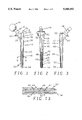
- FIG. 1 is a plan view of a femoral prosthesis according to our present invention, with attached femoral head.
- FIG. 2 is lateral plan view of the prosthesis stem of FIG. 1.
- FIG. 3 is an posterior plan view of the stem of FIG. 1.
- FIG. 4 is a prospective view of a double wedge of the proximal portion of the stem of FIG. 1.
- FIG. 5 is a top plan view of the wedge of FIG. 4.
- FIG. 6 is a left side plan view of the wedge of FIG. 4.
- FIG. 7 is a front plan view of the wedge of FIG. 4.
- FIG. 8 is a right plan view of the wedge of FIG. 4.
- FIG. 9 is a cross-section of a distal portion of the stem of FIG. 1 taken along line 9--9.
- FIG. 10 is anterior plan view of the stem of FIG. 1 showing our preferred location for porous coating.
- FIG. 11 is a lateral plan view of the stem of FIG. 10.
- FIG. 12 is an posterior plan view of the stem of FIG. 10.
- FIG. 13 is an enlarged partial plan view of the stem of FIG. 2, showing a flared distal slot.
- FIG. 1 a femoral prosthesis 10 is illustrated.
- the femoral prosthesis 10 comprises a stem 12 adapted to be inserted into the medullary canal of a resected femur and a spherical articulating head 14 mounted detachably on a neck 16.
- the stem 12 has a proximal body portion 18 and a distal portion 20.
- the distal portion is relatively straight on a lateral side 36 with a slight chamfer 22 proximally.
- the proximal portion is concave curved 24.
- an anterior side 28 and posterior side 26 are slightly flared proximally.
- a double wedge structure 30 which will be more fully described below.
- a collar 32 which extends anteriorly, medially and posteriorly from the proximal portion.
- the distal portion 20 of the stem is relatively straight, but is slightly tapered inwardly from the proximal portion to a distal end 34.
- a rib 38 which extends near the double wedge 30 to the distal tip 34.
- a proximal half 40 of this ridge 38 which comprises a first zone, the ridge is of relatively rectangular cross-section, providing sharp edges which could grip surrounding cancallous bone.
- anterior and posterior chamfers, 46, 44 respectively. These chamfers flare out from the ridge 40, widening the ridge and softening its outline.
- a slot 47 which extends in the medial-lateral plane from the distal end 34 about half of the distance from the distal end 34 to the beginning of the chamfers 44, 46, which comprises a distal zone.
- the slot 47 terminates at a stress relief bore 48.
- the slot 47 permits increased flexing of the prosthesis in anterior and posterior directions, reducing point pains which are frequently experienced by ,patients with femoral prostheses.
- ribs 50, 52 with substantially rectangular cross-sections extending from distal tip 34 approximately half of the extent of the stem from the distal tip to the collar 32.
- the ribs 50, 52 blend into the stem 12 at their proximal ends. They are, therefore, most prominent distally and become flatter proximally.
- corners of the distal portion of the stem have chamfers 54, 56, 58 and 60 which generally round the outline of the stem, but which still provide relatively sharp corners which will cut into surrounding cancellous bone as the stem is inserted into the medullary canal.
- the chamfers 44, 46 on the lateral rib 38 can also be seen in the cross-section of FIG. 9.
- the double wedge presents a wide distal blade 62 which is the distal extent of the double wedge feature.
- the distal blade 62 begins a plane 64 of a first wedge or taper which extends proximally and inclines away from the body of the proximal portion of the stem.
- the plane 64 terminates at a vertex 66.
- the plane 64 also defines a second wedge or taper which is broad distally at the blade 62 and narrow proximally at the vertex 66.
- the edge 62 terminates at a medial vertex 68 and a lateral vertex 70.
- These vertices 68, 70 are also vertices of similar inclined wedge planes, a medial wedge plane 72 and a lateral wedge plane 74. Each of these planes 72, 74 intersect at the proximal vertex 66. A medial edge 76 of the medial wedge plane 72 and a lateral edge 78 of the lateral wedge plane 74 flare away from each other from their respective vertices 68, 70 from distal to proximal location. The medial edge 76 and lateral edge 78 define a third taper which is broader proximally than it is distally. This structure, which can also be seen in plan view in FIGS. 5, 6, 7, and 8, creates opposed wedges.
- the distal edge 62 will first encounter bone. As the beginning of a wedge, this edge is wide and does not rapidly increase the stress in surrounding cortical bone. As the stem is thrust further into the medullary canal and the bone progresses from the edge 62 toward the vertex 66, the wedge plane 64 will press further and further into the surrounding cancellous and cortical bone, increasing fixation. At the same time, the width of this wedge plane 64 will decrease, allowing the stresses to diminish. Simultaneously, the flared features of the medial and lateral wedge planes 72, 74 will tend to fill more of the medullary canal.
- FIGS, 10, 11 and 12 illustrate the location of porous areas provided in our prosthesis. Although preferably comprised of porous titanium, these areas define a geometry more clearly seen in FIGS. 1, 2 and 3 and described above.
- a proximal porous portion 80 for the anterior side, seen in FIG. 10, would therefore, have the opposed wedge geometry described above.
- the proximal posterior porous area 82, seen in FIG. 12, would be of approximately equal area to the portion 80 but, in our preferred embodiment, would not have the opposed wedge configuration, although such a structure could be provided without departing from the teachings of our invention.
- a porous zone 84 is also provided medially, as is a porous zone 86 on the lateral side of our prosthesis.
- the porous portions 80, 82 and zones 84, 86 provide long-term proximal fixation as surrounding bone heals into the porous material.
- our prosthesis provides different fixation characteristics in both the anterior-posterior and the medial-lateral direction, using various portions and zones along the length of the prosthesis.
- a proximal portion which has the characteristics of both a porous area for long-term fixation and an opposed wedge for immediate fixation without unduly high stress.
- An intermediate portion separates this proximal porous portion from a distal portion.
- the ribs taper, becoming increasingly prominent distally, thereby providing an increased resistance to medial-lateral motion towards the distal end of the prosthesis.
Abstract
Description
Claims (9)
Priority Applications (1)
| Application Number | Priority Date | Filing Date | Title |
|---|---|---|---|
| US08/140,772 US5480452A (en) | 1992-05-29 | 1993-10-21 | Femoral prosthesis with wedge having opposed tapers |
Applications Claiming Priority (2)
| Application Number | Priority Date | Filing Date | Title |
|---|---|---|---|
| US07/889,823 US5258035A (en) | 1992-05-29 | 1992-05-29 | Femoral prosthesis with wedge having opposed tapers |
| US08/140,772 US5480452A (en) | 1992-05-29 | 1993-10-21 | Femoral prosthesis with wedge having opposed tapers |
Related Parent Applications (1)
| Application Number | Title | Priority Date | Filing Date |
|---|---|---|---|
| US07/889,823 Division US5258035A (en) | 1992-05-29 | 1992-05-29 | Femoral prosthesis with wedge having opposed tapers |
Publications (1)
| Publication Number | Publication Date |
|---|---|
| US5480452A true US5480452A (en) | 1996-01-02 |
Family
ID=25395859
Family Applications (2)
| Application Number | Title | Priority Date | Filing Date |
|---|---|---|---|
| US07/889,823 Expired - Lifetime US5258035A (en) | 1992-05-29 | 1992-05-29 | Femoral prosthesis with wedge having opposed tapers |
| US08/140,772 Expired - Lifetime US5480452A (en) | 1992-05-29 | 1993-10-21 | Femoral prosthesis with wedge having opposed tapers |
Family Applications Before (1)
| Application Number | Title | Priority Date | Filing Date |
|---|---|---|---|
| US07/889,823 Expired - Lifetime US5258035A (en) | 1992-05-29 | 1992-05-29 | Femoral prosthesis with wedge having opposed tapers |
Country Status (1)
| Country | Link |
|---|---|
| US (2) | US5258035A (en) |
Cited By (24)
| Publication number | Priority date | Publication date | Assignee | Title |
|---|---|---|---|---|
| US5683395A (en) * | 1996-04-26 | 1997-11-04 | Mikhail; W. E. Michael | System for performing hip prothesis revision surgery |
| US5718707A (en) * | 1997-01-22 | 1998-02-17 | Mikhail; W. E. Michael | Method and apparatus for positioning and compacting bone graft |
| WO1998006359A1 (en) * | 1996-08-13 | 1998-02-19 | Grimes James B | Femoral head-neck prosthesis and method of implantation |
| US6007581A (en) * | 1996-05-24 | 1999-12-28 | Stryker Technologies Corporation | Asymmetric hip stem |
| EP0966931A2 (en) * | 1996-12-23 | 1999-12-29 | JOHNSON & JOHNSON PROFESSIONAL Inc. | Alignment guide for fluted prosthetic stems |
| US6228092B1 (en) | 1999-07-29 | 2001-05-08 | W. E. Michael Mikhail | System for performing hip prosthesis surgery |
| US6371991B1 (en) | 1996-12-23 | 2002-04-16 | Depuy Orthopaedics, Inc. | Alignment guide for fluted prosthetic stems |
| US20030074079A1 (en) * | 1998-04-14 | 2003-04-17 | Osteoimplant Technology, Inc. | Differential porosity prosthetic hip system |
| US20040010319A1 (en) * | 1998-04-14 | 2004-01-15 | Osteoimplant Technology Inc. | Intrinsic stability in a total hip stem |
| EP1438933A1 (en) * | 2003-01-17 | 2004-07-21 | WALDEMAR LINK GmbH & Co. KG | Hip prosthesis with a stem to be implanted into the medullary canal of the femur |
| US6783553B2 (en) | 2001-10-24 | 2004-08-31 | James B. Grimes | Prosthesis |
| US20050165493A1 (en) * | 2004-01-22 | 2005-07-28 | Ries Michael D. | Femoral hip prosthesis and method of implantation |
| US20060206212A1 (en) * | 1999-04-13 | 2006-09-14 | Karl Zweymuller | Leaflike shaft of a hip-joint prosthesis for anchoring in the femur |
| US20060276904A1 (en) * | 2000-04-13 | 2006-12-07 | Karl Zweymuller | Leaflike shaft of a hip-joint prosthesis for anchoring in the femur |
| US20070010891A1 (en) * | 2003-07-16 | 2007-01-11 | Waldemar Link Bmbh & Co. Kg | Hip prosthesis provided with a shaft inserted into the femur |
| US20080039941A1 (en) * | 1997-04-15 | 2008-02-14 | Active Implants Corporation | Bone growth promoting implant |
| US20080200990A1 (en) * | 2007-02-16 | 2008-08-21 | Mctighe Timothy | Tissue sparing implant |
| US7497875B1 (en) * | 1999-04-07 | 2009-03-03 | Smith & Nephew Orthopaedics Ag | Flat shaft of a hip-joint prosthesis for anchoring in the femur |
| US20090149964A1 (en) * | 2007-10-10 | 2009-06-11 | Biomet Manufacturing Corp. | Knee joint prosthesis system and method for implantation |
| US20090299482A1 (en) * | 2007-01-10 | 2009-12-03 | Biomet Manufacturing Corp. | Knee Joint Prosthesis System and Method for Implantation |
| US20100249942A1 (en) * | 2009-03-27 | 2010-09-30 | Wright State University | Toe joint replacement models |
| US8157869B2 (en) | 2007-01-10 | 2012-04-17 | Biomet Manufacturing Corp. | Knee joint prosthesis system and method for implantation |
| US8187280B2 (en) | 2007-10-10 | 2012-05-29 | Biomet Manufacturing Corp. | Knee joint prosthesis system and method for implantation |
| US8328873B2 (en) | 2007-01-10 | 2012-12-11 | Biomet Manufacturing Corp. | Knee joint prosthesis system and method for implantation |
Families Citing this family (16)
| Publication number | Priority date | Publication date | Assignee | Title |
|---|---|---|---|---|
| EP0543099A3 (en) * | 1991-11-19 | 1994-05-25 | Bristol Myers Squibb Co | Implant fixation stem |
| US5507832B1 (en) * | 1993-10-26 | 1999-07-27 | Howmedica | Prosthesis with integral proximal spacer |
| US5593451A (en) * | 1994-06-01 | 1997-01-14 | Implex Corp. | Prosthetic device and method of implantation |
| DE69621087T2 (en) * | 1995-08-25 | 2004-04-01 | Bristol-Myers Squibb Co. | Prosthetic implant with ribs |
| FR2744628B1 (en) * | 1996-02-08 | 1998-04-17 | Deckner Andre Georges | PROSTHESIS ANCHOR ROD |
| IT1290643B1 (en) * | 1997-01-17 | 1998-12-10 | Stefano Orsi | DISTAL TERMINAL FOR PRIMARY HIP PROSTHESIS STEM. |
| GB9814274D0 (en) * | 1998-07-01 | 1998-09-02 | Johnson & Johnson Medical Ltd | Prosthetic component |
| GB9814267D0 (en) * | 1998-07-01 | 1998-09-02 | Johnson & Johnson Medical Ltd | Prosthetic component |
| US6361566B1 (en) | 2000-03-10 | 2002-03-26 | Bashar Al-Hafez | Hip prosthesis |
| AUPR526301A0 (en) * | 2001-05-25 | 2001-06-21 | Howie, Donald W. | Prosthetic implant |
| US7494509B1 (en) | 2002-02-04 | 2009-02-24 | Biomet Manufacturing Corp. | Method and apparatus for providing a short-stemmed hip prosthesis |
| FR2842725B1 (en) * | 2002-07-26 | 2005-05-20 | Jean Louis Dore | RANGE OF FEMALE IMPLANTS OF HIP PROSTHESIS, IN PARTICULAR REPRISE. |
| US6656187B1 (en) * | 2002-09-03 | 2003-12-02 | Depuy Products, Inc. | Adjustable orthopaedic instrument |
| US20070270863A1 (en) * | 2006-04-20 | 2007-11-22 | Sdgi Holdings, Inc. | Devices and methods for contouring an intervertebral space between vertebral members |
| GB2534141A (en) * | 2015-01-13 | 2016-07-20 | Imp Innovations Ltd | Hip stem |
| EP4169487A1 (en) | 2015-09-30 | 2023-04-26 | David Phillip Kirwan | Hip prosthesis |
Citations (14)
| Publication number | Priority date | Publication date | Assignee | Title |
|---|---|---|---|---|
| US3466670A (en) * | 1965-05-26 | 1969-09-16 | Tor Christiansen | Hip-joint prosthesis |
| DE3132543A1 (en) * | 1980-11-25 | 1982-06-03 | Gebrüder Sulzer AG, 8401 Winterthur | Femoral head prosthesis |
| US4404693A (en) * | 1980-01-14 | 1983-09-20 | Sulzer Brothers Limited | Shank for a hip joint prosthesis |
| EP0050533B1 (en) * | 1980-10-17 | 1985-02-27 | Francis Henri Bréard | Femoral head endoprothesis with self locking stem |
| US4608053A (en) * | 1982-05-03 | 1986-08-26 | Waldemar Link Gmbh & Co. | Femoral hip prosthesis |
| US4645506A (en) * | 1983-06-27 | 1987-02-24 | Waldemar Link Gmbh & Co. | Hip joint endoprosthesis with a stem to be anchored in the femur |
| EP0229578A1 (en) * | 1985-12-24 | 1987-07-22 | Christian Mai | Self-clamping medical prostheses and process for manufacturing same |
| US4718916A (en) * | 1985-06-12 | 1988-01-12 | Sulzer Brothers Ltd. | Femur head prosthesis |
| US4904269A (en) * | 1986-10-25 | 1990-02-27 | Paulo Gallinaro | Hip joint prosthesis |
| US4911722A (en) * | 1986-08-25 | 1990-03-27 | Office Medico Chirurgical International S.A. (O.M.C.I.) | Mechanical self locking femoral prosthesis and a method for implementing same |
| US4936863A (en) * | 1988-05-13 | 1990-06-26 | Hofmann Aaron A | Hip prosthesis |
| US4944761A (en) * | 1989-01-10 | 1990-07-31 | Sulzer Brothers Limited | Blade-like stem for a femoral head prosthesis |
| US4997444A (en) * | 1989-12-28 | 1991-03-05 | Zimmer, Inc. | Implant having varying modulus of elasticity |
| US5316550A (en) * | 1986-04-07 | 1994-05-31 | Mark Forte | Prosthesis with flexible intramedullary stem |
Family Cites Families (1)
| Publication number | Priority date | Publication date | Assignee | Title |
|---|---|---|---|---|
| JPS62100751A (en) * | 1985-10-24 | 1987-05-11 | インタ−ナショナル ビジネス マシ−ンズ コ−ポレ−ション | Formation of self-matching pattern |
-
1992
- 1992-05-29 US US07/889,823 patent/US5258035A/en not_active Expired - Lifetime
-
1993
- 1993-10-21 US US08/140,772 patent/US5480452A/en not_active Expired - Lifetime
Patent Citations (14)
| Publication number | Priority date | Publication date | Assignee | Title |
|---|---|---|---|---|
| US3466670A (en) * | 1965-05-26 | 1969-09-16 | Tor Christiansen | Hip-joint prosthesis |
| US4404693A (en) * | 1980-01-14 | 1983-09-20 | Sulzer Brothers Limited | Shank for a hip joint prosthesis |
| EP0050533B1 (en) * | 1980-10-17 | 1985-02-27 | Francis Henri Bréard | Femoral head endoprothesis with self locking stem |
| DE3132543A1 (en) * | 1980-11-25 | 1982-06-03 | Gebrüder Sulzer AG, 8401 Winterthur | Femoral head prosthesis |
| US4608053A (en) * | 1982-05-03 | 1986-08-26 | Waldemar Link Gmbh & Co. | Femoral hip prosthesis |
| US4645506A (en) * | 1983-06-27 | 1987-02-24 | Waldemar Link Gmbh & Co. | Hip joint endoprosthesis with a stem to be anchored in the femur |
| US4718916A (en) * | 1985-06-12 | 1988-01-12 | Sulzer Brothers Ltd. | Femur head prosthesis |
| EP0229578A1 (en) * | 1985-12-24 | 1987-07-22 | Christian Mai | Self-clamping medical prostheses and process for manufacturing same |
| US5316550A (en) * | 1986-04-07 | 1994-05-31 | Mark Forte | Prosthesis with flexible intramedullary stem |
| US4911722A (en) * | 1986-08-25 | 1990-03-27 | Office Medico Chirurgical International S.A. (O.M.C.I.) | Mechanical self locking femoral prosthesis and a method for implementing same |
| US4904269A (en) * | 1986-10-25 | 1990-02-27 | Paulo Gallinaro | Hip joint prosthesis |
| US4936863A (en) * | 1988-05-13 | 1990-06-26 | Hofmann Aaron A | Hip prosthesis |
| US4944761A (en) * | 1989-01-10 | 1990-07-31 | Sulzer Brothers Limited | Blade-like stem for a femoral head prosthesis |
| US4997444A (en) * | 1989-12-28 | 1991-03-05 | Zimmer, Inc. | Implant having varying modulus of elasticity |
Cited By (45)
| Publication number | Priority date | Publication date | Assignee | Title |
|---|---|---|---|---|
| US5683395A (en) * | 1996-04-26 | 1997-11-04 | Mikhail; W. E. Michael | System for performing hip prothesis revision surgery |
| WO1997040785A1 (en) * | 1996-04-26 | 1997-11-06 | Mikhail Michael W E | System for performing hip prosthesis revision surgery |
| US6007581A (en) * | 1996-05-24 | 1999-12-28 | Stryker Technologies Corporation | Asymmetric hip stem |
| WO1998006359A1 (en) * | 1996-08-13 | 1998-02-19 | Grimes James B | Femoral head-neck prosthesis and method of implantation |
| US6273915B1 (en) | 1996-08-13 | 2001-08-14 | James B. Grimes | Femoral head-neck prosthesis and method of implantation |
| EP0966931A2 (en) * | 1996-12-23 | 1999-12-29 | JOHNSON & JOHNSON PROFESSIONAL Inc. | Alignment guide for fluted prosthetic stems |
| EP0978262A1 (en) * | 1996-12-23 | 2000-02-09 | Johnson & Johnson Professional, Inc. | Alignment guide for slotted prosthetic stem |
| EP0966931A3 (en) * | 1996-12-23 | 2000-11-15 | JOHNSON & JOHNSON PROFESSIONAL Inc. | Alignment guide for fluted prosthetic stems |
| US6371991B1 (en) | 1996-12-23 | 2002-04-16 | Depuy Orthopaedics, Inc. | Alignment guide for fluted prosthetic stems |
| US5718707A (en) * | 1997-01-22 | 1998-02-17 | Mikhail; W. E. Michael | Method and apparatus for positioning and compacting bone graft |
| US5925051A (en) * | 1997-01-22 | 1999-07-20 | Mikhail; W.E. Michael | Method and apparatus for positioning and compacting bone graft |
| US20080039941A1 (en) * | 1997-04-15 | 2008-02-14 | Active Implants Corporation | Bone growth promoting implant |
| US20070043448A1 (en) * | 1998-04-14 | 2007-02-22 | Encore Medical Asset Corporation | Intrinsic stability in a total hip stem |
| US20040010319A1 (en) * | 1998-04-14 | 2004-01-15 | Osteoimplant Technology Inc. | Intrinsic stability in a total hip stem |
| US20030074079A1 (en) * | 1998-04-14 | 2003-04-17 | Osteoimplant Technology, Inc. | Differential porosity prosthetic hip system |
| US7497875B1 (en) * | 1999-04-07 | 2009-03-03 | Smith & Nephew Orthopaedics Ag | Flat shaft of a hip-joint prosthesis for anchoring in the femur |
| US7455693B2 (en) | 1999-04-13 | 2008-11-25 | Smith & Nephew Orthopaedics, Ag | Leaflike shaft of a hip-joint prosthesis for anchoring in the femur |
| US20060206212A1 (en) * | 1999-04-13 | 2006-09-14 | Karl Zweymuller | Leaflike shaft of a hip-joint prosthesis for anchoring in the femur |
| US6228092B1 (en) | 1999-07-29 | 2001-05-08 | W. E. Michael Mikhail | System for performing hip prosthesis surgery |
| US20060276904A1 (en) * | 2000-04-13 | 2006-12-07 | Karl Zweymuller | Leaflike shaft of a hip-joint prosthesis for anchoring in the femur |
| US7494510B2 (en) | 2000-04-13 | 2009-02-24 | Smith And Nephew Orthopaedics Ag | Leaflike shaft of a hip-joint prosthesis for anchoring in the femur |
| US6783553B2 (en) | 2001-10-24 | 2004-08-31 | James B. Grimes | Prosthesis |
| EP1438933A1 (en) * | 2003-01-17 | 2004-07-21 | WALDEMAR LINK GmbH & Co. KG | Hip prosthesis with a stem to be implanted into the medullary canal of the femur |
| US7559950B2 (en) * | 2003-01-17 | 2009-07-14 | Waldemar Link Gmbh & Co. Kg | Hip prosthesis including a shaft to be fixed in the medullary canal of the femur |
| US20060041316A1 (en) * | 2003-01-17 | 2006-02-23 | Waldemar Link Gmbh 7 Co. Kg | Hip prosthesis comprising a shaft to be fixed in the medullary canal of the femur |
| US7553333B2 (en) * | 2003-07-16 | 2009-06-30 | Waldemar Link Gmbh & Co. Kg | Hip prosthesis provided with a shaft inserted into the femur |
| US20070010891A1 (en) * | 2003-07-16 | 2007-01-11 | Waldemar Link Bmbh & Co. Kg | Hip prosthesis provided with a shaft inserted into the femur |
| US20110004319A1 (en) * | 2004-01-22 | 2011-01-06 | Michael D. Ries | Femoral Hip Prosthesis and Method of Implantation |
| WO2005069810A3 (en) * | 2004-01-22 | 2005-10-20 | Medicinelodge Inc | Femoral hip prosthesis and method of implantation |
| US8157871B2 (en) | 2004-01-22 | 2012-04-17 | Michael D Ries | Femoral HIP prosthesis and method of implantation |
| US20050165493A1 (en) * | 2004-01-22 | 2005-07-28 | Ries Michael D. | Femoral hip prosthesis and method of implantation |
| US20090216335A1 (en) * | 2004-01-22 | 2009-08-27 | Smith & Nephew | Femoral Hip Prosthesis and Method of Implantation |
| US20090299482A1 (en) * | 2007-01-10 | 2009-12-03 | Biomet Manufacturing Corp. | Knee Joint Prosthesis System and Method for Implantation |
| US8163028B2 (en) | 2007-01-10 | 2012-04-24 | Biomet Manufacturing Corp. | Knee joint prosthesis system and method for implantation |
| US8328873B2 (en) | 2007-01-10 | 2012-12-11 | Biomet Manufacturing Corp. | Knee joint prosthesis system and method for implantation |
| US8480751B2 (en) | 2007-01-10 | 2013-07-09 | Biomet Manufacturing, Llc | Knee joint prosthesis system and method for implantation |
| US8936648B2 (en) | 2007-01-10 | 2015-01-20 | Biomet Manufacturing, Llc | Knee joint prosthesis system and method for implantation |
| US8157869B2 (en) | 2007-01-10 | 2012-04-17 | Biomet Manufacturing Corp. | Knee joint prosthesis system and method for implantation |
| US20080200990A1 (en) * | 2007-02-16 | 2008-08-21 | Mctighe Timothy | Tissue sparing implant |
| US10736747B2 (en) | 2007-10-10 | 2020-08-11 | Biomet Manufacturing, Llc | Knee joint prosthesis system and method for implantation |
| US20090149964A1 (en) * | 2007-10-10 | 2009-06-11 | Biomet Manufacturing Corp. | Knee joint prosthesis system and method for implantation |
| US8187280B2 (en) | 2007-10-10 | 2012-05-29 | Biomet Manufacturing Corp. | Knee joint prosthesis system and method for implantation |
| US8562616B2 (en) | 2007-10-10 | 2013-10-22 | Biomet Manufacturing, Llc | Knee joint prosthesis system and method for implantation |
| US9763793B2 (en) | 2007-10-10 | 2017-09-19 | Biomet Manufacturing, Llc | Knee joint prosthesis system and method for implantation |
| US20100249942A1 (en) * | 2009-03-27 | 2010-09-30 | Wright State University | Toe joint replacement models |
Also Published As
| Publication number | Publication date |
|---|---|
| US5258035A (en) | 1993-11-02 |
Similar Documents
| Publication | Publication Date | Title |
|---|---|---|
| US5480452A (en) | Femoral prosthesis with wedge having opposed tapers | |
| US10426623B2 (en) | Hip stem prosthesis | |
| US4546501A (en) | Hip prosthesis | |
| US4846839A (en) | Apparatus for affixing a prosthesis to bone | |
| CA2205727C (en) | Asymmetric hip stem | |
| EP0761183B1 (en) | Prosthetic implant with fins | |
| US4813963A (en) | Femoral component for a hip prosthesis | |
| US4589883A (en) | Femoral hip prosthesis | |
| US2934065A (en) | Femoral intramedullary prosthesis | |
| US5863295A (en) | Prosthetic device and method of implantation | |
| US5755805A (en) | Tapered prosthesis component | |
| US4608053A (en) | Femoral hip prosthesis | |
| US6699293B2 (en) | Prosthesis having wedge-shaped body | |
| US6520994B2 (en) | Shoulder endoprosthesis for fractures of the upper end of the humerus | |
| US4536894A (en) | Hip prosthesis with flared porous bony ingrowth pads | |
| US9161840B2 (en) | Modular prosthetic component with improved body shape | |
| EP0985385B1 (en) | Implantable prosthesis with bone engaging ribs | |
| US20040064187A1 (en) | Humeral shoulder prosthesis | |
| US4163292A (en) | Hip prosthesis | |
| JPH02174844A (en) | Prosthetic appliance for implantation and prosthetic method therefor | |
| MXPA03005235A (en) | Massive modular system. | |
| EP0622061A1 (en) | Femoral component for a hip prothesis | |
| AU2001292950A1 (en) | Modular prosthetic component with improved body shape | |
| USRE32488E (en) | Hip prosthesis | |
| JPH08904U (en) | Thigh member of hip joint artificial bone |
Legal Events
| Date | Code | Title | Description |
|---|---|---|---|
| AS | Assignment |
Owner name: INTERMEDICS ORTHOPEDICS, INC., TEXAS Free format text: ASSIGNMENT OF ASSIGNORS INTEREST;ASSIGNORS:HOFMANN, AARON A.;WILLIAMS, JAMES E.;REEL/FRAME:007275/0437 Effective date: 19941031 |
|
| STCF | Information on status: patent grant |
Free format text: PATENTED CASE |
|
| FEPP | Fee payment procedure |
Free format text: PAYOR NUMBER ASSIGNED (ORIGINAL EVENT CODE: ASPN); ENTITY STATUS OF PATENT OWNER: LARGE ENTITY |
|
| FPAY | Fee payment |
Year of fee payment: 4 |
|
| AS | Assignment |
Owner name: CENTERPULSE ORTHOPEDICS INC., TEXAS Free format text: CHANGE OF NAME;ASSIGNOR:SULZER ORTHOPEDICS INC.;REEL/FRAME:013516/0549 Effective date: 20020930 |
|
| FPAY | Fee payment |
Year of fee payment: 8 |
|
| AS | Assignment |
Owner name: SULZER ORTHOPEDICS, INC., ILLINOIS Free format text: CHANGE OF NAME;ASSIGNOR:INTERMEDICS ORTHOPEDICS, INC.;REEL/FRAME:015177/0137 Effective date: 19970106 |
|
| AS | Assignment |
Owner name: CENTERPULSE ORTHOPEDICS INC., TEXAS Free format text: CHANGE OF NAME;ASSIGNOR:SULZER ORTHOPEDICS INC.;REEL/FRAME:016761/0136 Effective date: 20020930 |
|
| FPAY | Fee payment |
Year of fee payment: 12 |
|
| AS | Assignment |
Owner name: ZIMMER, INC., INDIANA Free format text: ASSIGNMENT OF ASSIGNORS INTEREST;ASSIGNOR:HOFMANN, AARON A.;REEL/FRAME:022793/0354 Effective date: 20090319 |