US5469980A - Child resistant container closure assembly - Google Patents
Child resistant container closure assembly Download PDFInfo
- Publication number
- US5469980A US5469980A US08/188,596 US18859694A US5469980A US 5469980 A US5469980 A US 5469980A US 18859694 A US18859694 A US 18859694A US 5469980 A US5469980 A US 5469980A
- Authority
- US
- United States
- Prior art keywords
- piercing
- nozzle
- closure
- container
- piercing portion
- Prior art date
- Legal status (The legal status is an assumption and is not a legal conclusion. Google has not performed a legal analysis and makes no representation as to the accuracy of the status listed.)
- Expired - Lifetime
Links
Images


Classifications
-
- B—PERFORMING OPERATIONS; TRANSPORTING
- B65—CONVEYING; PACKING; STORING; HANDLING THIN OR FILAMENTARY MATERIAL
- B65D—CONTAINERS FOR STORAGE OR TRANSPORT OF ARTICLES OR MATERIALS, e.g. BAGS, BARRELS, BOTTLES, BOXES, CANS, CARTONS, CRATES, DRUMS, JARS, TANKS, HOPPERS, FORWARDING CONTAINERS; ACCESSORIES, CLOSURES, OR FITTINGS THEREFOR; PACKAGING ELEMENTS; PACKAGES
- B65D51/00—Closures not otherwise provided for
- B65D51/18—Arrangements of closures with protective outer cap-like covers or of two or more co-operating closures
- B65D51/20—Caps, lids, or covers co-operating with an inner closure arranged to be opened by piercing, cutting, or tearing
- B65D51/22—Caps, lids, or covers co-operating with an inner closure arranged to be opened by piercing, cutting, or tearing having means for piercing, cutting, or tearing the inner closure
- B65D51/221—Caps, lids, or covers co-operating with an inner closure arranged to be opened by piercing, cutting, or tearing having means for piercing, cutting, or tearing the inner closure a major part of the inner closure being left inside the container after the opening
- B65D51/222—Caps, lids, or covers co-operating with an inner closure arranged to be opened by piercing, cutting, or tearing having means for piercing, cutting, or tearing the inner closure a major part of the inner closure being left inside the container after the opening the piercing or cutting means being integral with, or fixedly attached to, the outer closure
- B65D51/223—Caps, lids, or covers co-operating with an inner closure arranged to be opened by piercing, cutting, or tearing having means for piercing, cutting, or tearing the inner closure a major part of the inner closure being left inside the container after the opening the piercing or cutting means being integral with, or fixedly attached to, the outer closure the outer closure having to be removed or inverted for piercing or cutting
-
- B—PERFORMING OPERATIONS; TRANSPORTING
- B65—CONVEYING; PACKING; STORING; HANDLING THIN OR FILAMENTARY MATERIAL
- B65D—CONTAINERS FOR STORAGE OR TRANSPORT OF ARTICLES OR MATERIALS, e.g. BAGS, BARRELS, BOTTLES, BOXES, CANS, CARTONS, CRATES, DRUMS, JARS, TANKS, HOPPERS, FORWARDING CONTAINERS; ACCESSORIES, CLOSURES, OR FITTINGS THEREFOR; PACKAGING ELEMENTS; PACKAGES
- B65D2251/00—Details relating to container closures
- B65D2251/0003—Two or more closures
- B65D2251/0006—Upper closure
- B65D2251/0015—Upper closure of the 41-type
-
- B—PERFORMING OPERATIONS; TRANSPORTING
- B65—CONVEYING; PACKING; STORING; HANDLING THIN OR FILAMENTARY MATERIAL
- B65D—CONTAINERS FOR STORAGE OR TRANSPORT OF ARTICLES OR MATERIALS, e.g. BAGS, BARRELS, BOTTLES, BOXES, CANS, CARTONS, CRATES, DRUMS, JARS, TANKS, HOPPERS, FORWARDING CONTAINERS; ACCESSORIES, CLOSURES, OR FITTINGS THEREFOR; PACKAGING ELEMENTS; PACKAGES
- B65D2251/00—Details relating to container closures
- B65D2251/0003—Two or more closures
- B65D2251/0068—Lower closure
- B65D2251/0093—Membrane
- B65D2251/0096—Membrane integral with the container
Definitions
- the present invention relates to child resistant container-closure assemblies and more specifically to improvements facilitating precise activation of the container when it is desired to withdraw the contents.
- Container-closure assemblies of the type to which the present invention relate typically comprise a container made of plastic having a nozzle portion with a puncturable diaphragm defining a discharge opening and a closure or cap having a piercing element selectively engageable in the diaphragm to form a discharge opening when it is desired to remove the contents of the container.
- Container-closure assemblies of this general type are not new per se. For example, the patents listed below show container-closure assemblies of this general type:
- the piercing element in the assemblies where the piercing element is on another portion of the closure, unless it is applied in a truly axial direction, the piercing element tends to engage the thick wall portion of the nozzle surrounding the diaphragm which increases the force necessary by the user in the puncturing process.
- the present invention provides an improved container-closure assembly which obviates the problems in the prior art noted above.
- the present invention is characterized by novel features of construction and arrangement facilitating application of the closure during the piercing process with a minimum force requirement and thereby obviates the problem of "spurting."
- the particular configuration of the piercing element is such that even if the closure piercing element is presented at a slight angle to the axis of the container, the piercing element is nevertheless directed to the diaphragm when it is moved in a direction to apply it to the nozzle.
- the assembly of the present invention is self aligning and is characterized by minimum contact between the parts and thus produces very minimal, low friction during the piercing process.
- the major force during the piercing process is that of sharpened piercing element engaging the diaphragm.
- FIG. 1 is a side elevational view of a container-closure assembly in accordance with the present invention
- FIG. 2 is a plan view of FIG. 1;
- FIG. 3 is an enlarged fragmentary sectional elevational view taken on the lines 3--3 of FIG. 1 showing details of the closure and nozzle of the closure assembled in a shelf storage mode;
- FIG. 4. is a sectional plan view taken on the lines 4--4 of FIG. 3 showing additional details of the closure and nozzle;
- FIG. 5 is an enlarged sectional elevational view of the closure showing the desired dimensions of the pierce point tip recessed within the closure;
- FIG. 6 is a sectional view taken on lines 6--6 of FIG. 5;
- FIG. 7 is a side elevational view of the container nozzle
- FIG. 8 is an enlarged fragmentary view with the closure in section illustrating the closure being applied to the nozzle but not aligned with the container nozzle;
- FIG. 9 is a view similar to FIG. 8 showing that the closure pivoted about one of the arcuately faced ribs positioning the closure in axial alignment with the nozzle axis;
- FIG. 10 is an enlarged sectional plan view taken on lines 10--10 of FIG. 9;
- FIG. 11 shows the closure moved downwardly in the diaphragm piercing position
- FIG. 12 is a side elevational view of another embodiment of container-closure assembly in accordance with the present invention.
- FIG. 13 is a top plan view of the embodiment shown in FIG. 12;
- FIG. 14 is a fragmentary side elevational view taken on lines 14--14 of FIG. 12;
- FIG. 15 is an enlarged plan sectional view taken on lines 15--15 of FIG. 14;
- FIG. 16 is a transverse sectional view of the piercing closure member
- FIG. 17 is a sectional plan view taken on the line 17--17 of FIG. 16;
- FIG. 18 is a fragmentary elevational view of the nozzle portion of the container.
- FIG. 19 is an enlarged fragmentary elevational view showing the piercing element applied to the nozzle at an angular disposition
- FIG. 20 is a view similar to FIG. 19 showing the axial orientation of the cap on the nozzle;
- FIG. 21 is a sectional view taken on lines 21--21 of FIG. 20;
- FIG. 22 is a view similar to the previous two views showing the cap fully seated in the piercing diaphragm position
- FIG. 23 is a side elevational view of still another embodiment of container-closure assembly in accordance with the present invention.
- FIG. 24 is a top plan view of the embodiment shown in FIG. 23;
- FIG. 25 is a fragmentary side elevational view taken on lines 25--25 of FIG. 23;
- FIG. 26 is an enlarged plan sectional view taken on lines 26--26 of FIG. 25;
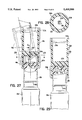
- FIG. 27 is an enlarged fragmentary elevational view showing the piercing closure applied to the nozzle at an angular disposition
- FIG. 28 is a sectional view taken on lines 28--28 of FIG. 27;
- FIG. 29 is a view similar to the previous two views showing the cap fully seated in the piercing diaphragm position
- FIG. 30 is a side elevational view of still another embodiment of container-closure assembly in accordance with the present invention.
- FIG. 31 is a top plan view of the embodiment shown in FIG. 30;
- FIG. 32 is an enlarged fragmentary side elevational view partially in section taken on lines 32--32 of FIG. 30;
- FIG. 33 is a plan sectional view taken on lines 33--33 of FIG. 32;
- FIG. 34 is a sectional elevational view of the closure for the embodiment of FIG. 30;
- FIG. 35 is a side elevational view of the nozzle portion of the container of FIG. 30;
- FIG. 36 is a plan view taken on the line 36--36 of FIG. 35;
- FIG. 37 is an enlarged fragmentary elevational view showing the piercing closure applied to the nozzle at an angular disposition
- FIG. 38 is an enlarged fragmentary elevational view showing the piercing closure applied to the nozzle at an angular disposition as shown in dot and dash line and being rotated into axial alignment with the nozzle axis, shown in full line in order to push the closure down the nozzle into piercing engagement with the nozzle diaphragm;
- FIG. 39 is a view similar to the previous two views showing the cap fully seated in the piercing diaphragm position
- the container designated by the numeral 10 is a unit dose tube for medicaments having an elongated nozzle 12 at one axial end and a piercable diaphragm 14 in its outer axial end face to define a discharge opening for discharging medicaments when desired.
- the closure generally designated by the numeral 16 comprises a cap portion 18 and a diaphragm piercing portion 20.
- the cap portion 18 and piercing portion 20 are of generally cylindrical shape and are separated by a center wall 22.
- the cap portion 18 is of a predetermined length L to overlie the nozzle 12 when applied thereto in a sealing condition shown in FIG. 3.
- Inner engaging locking means is provided on the nozzle 12 and cap portion 18 for normally seating the cap portion and providing a child resistant feature.
- the locking means comprises a circumferentially extending, radially outwardly directed locking ring 24 spaced upwardly from the juncture of the nozzle 12 and body portion 10 a of the container.
- a circumferentially extending locking groove 26 is provided on the interior wall of the cap portion 18 adjacent its lower terminal edge which snap fits over the locking ring 24 to retain the parts in the position shown in FIG. 3.
- the inner edge of the cap portion 18 is bevelled outwardly as at 28 to facilitate assembly of the cap portion 18 over the locking ring 24 by simply pressing the cap portion 18 downwardly during the assembly process.
- the exterior wall of the cap portion 18 is knurled as at 30 to facilitate assembly and removal of the cap portion by a user.
- the piercing portion 20 of the closure is of cup-like configuration and is of a shorter axial length L p than the diameter D of the pocket and includes a piercing element 34 centrally located in the center wall 22 having a biased or slanted cutting edge 36.
- the exterior of the cap portion 18 is also knurled as at 38 to facilitate handling by a user during manipulation of the cap through various operations.
- the nozzle is provided with a series of circumferentially spaced, longitudinally extending ribs 40.
- the ribs 40 are preferably of a tear drop shape so that lower portion of the ribs 40 bevel downwardly and inwardly at a predetermined angle ⁇ relative to the central axis A--A of the nozzle.
- the enlarged end of each rib 40 as shown in FIG. 7 is also rounded as at 44.
- the ribs thus have a curved outer peripheral shape including a radius R 1 at a point of maximum engagement with the inner walls of the piercing portion 20 of the closure. It is noted that the apex point 41 of the ribs engages the interior wall of the cap portion as best illustrated in FIGS. 3 and 4 to reduce friction upon application of the cap to the nozzle 12 and stabilize the cap portion in the fully seated position shown in FIG. 3.
- the ribs 40 engage in the grooves or trackways 42 during application of the piercing portion 20 of the cap to the nozzle 12 in the manner shown in FIGS. 8 and 9 and function to align the cap portion 18 axially with the nozzle for accurate penetration of the piercing element 34 to puncture the diaphragm 14.
- the rib 40 and groove 42 arrangement also provides a degree of child resistance since alignment of the groove 42 and ribs 40 is necessary to full seating of the piercing element 34 to penetrate the diaphragm. Further the rib and groove arrangement, particularly the arcuate configuration of the grooves reduces friction during assembly of the closure. In this regard, the radius R 1 of the ribs is smaller than the radius R 2 of the grooves to produce the lower friction and point contact between the parts during a piercing operation.
- the closure is preferably provided with six circumferentially equi-spaced grooves 42 reducing the rotation needed to align the nozzle to an axial piercing position.
- the piercing portion of the closure is designed to prevent engagement of the piercing element 34 with other portions of the nozzle during initial application of the closure 16 regardless of the initial angle of entry. This insures axial alignment of the piercing point 36 with the diaphragm 14 before engagement of the diaphragm the piercing element to puncture the diaphragm 14.
- the tip 48 of the piercing element is spaced inwardly from a plane P--P through the lower terminal edge of the piercing portion, a predetermined distance D equal to at least 1/2 the inner diameter D i of the piercing portion 20 of the closure.
- the interior side wall of the piercing portion 20 snugly embraces the nozzle 12 for proper guidance and yet as shown in FIG. 10 has a small clearance to provide the low friction point contacts during assembly and disassembly of the piercing portion to the nozzle. This relationship provides the desired functional advantages discussed in a piercing portion of minimum height to enhance the cosmetics of the closure assembly.
- the unit dose tubes have an open lower end for filling the product and are pinch sealed after being filled by automatic processing equipment.
- the closure 16 is then applied with the cap portion seated over the nozzle in the manner shown in FIG. 3.
- the locking ring 24 and groove 26 arrangement provides a degree of child resistancy to the assembly.
- the engagement of the ribs with the inner side wall of the cap portion at the apex of the ribs centers the closure on the tube. In other words, the closure is centered on the same axis as the tube axis.
- the user when it is desired to dispense the contents of the tube, the user simply withdraws the closure axially and reverses the closure so that the piercing portion faces downwardly over the nozzle.
- the piercing portion is rotated slightly if necessary to align the ribs in the grooves and by simply urging it axially over the nozzle automatically aligns itself axially to position the piercing element in alignment with the diaphragm.
- This obviates the problem of cockeyed application of the piercing portion to the nozzle which could result in the user attempting to pierce the thick walled portion surrounding the diaphragm. This is particularly important in nursing applications where the systems are activated sometimes in a dimly lit area.
- the rib and groove configuration provides minimum contact areas between the piercing portion and nozzle thereby reducing friction during the piercing process. This also permits a gentle holding force minimizing the "spurting" phenomenon resulting from occasion by squeezing the tube with a large force during the penetration operation.
- FIGS. 12-22 another embodiment of child resistant container-closure assembly in accordance with the present invention.
- the basic components of this assembly are the same as the previously described embodiment.
- Like parts are designated with the same numeral with an "a" .
- the assembly includes a container 13 a having a nozzle portion 12 a with a puncturable diaphragm 14 a defining a discharge opening.
- the closure is an elongated tubular member 16 a having a piercing portion 20 a of cup like form and a cap portion 18 a at 21 a .
- the piercing portion has a piercing element 34 a projecting from the center wall 22 a .
- the preferred axial distance D to the tip of the piercing member from the open end of the portion is preferably at least 1/2 the inner diameter D i of the piercing portion 20 a .
- the circumferentially spaced ribs 40 a on the nozzle portion of the closure 12 a are of square cross section.
- the ribs 40 a taper gently and downwardly merge with the nozzle in the manner shown in FIG. 18 and have a slightly rounded upper edge as at 41 a .
- the piercing portion 20 a of the closure is provided with a series of circumferentially spaced, axially extending recesses defining pockets 42 a and are of a complementary square cross section to snugly embrace the ribs 40 a which as indicated above are also of square cross section.
- the exterior circumferential wall of the piercing portion is knurled as at 38 a and in the present instance has a gap 39 in the knurling located adjacent one of the grooves 42 a which defines indicia for aligning the grooves with the ribs when applying the piercing portion to the nozzle of the container.
- FIGS. 24-29 still another embodiment of container as closure assembly in accordance with the present invention.
- the basic elements of this assembly are similar to those described previously and accordingly similar parts are designated by the same numeral with a letter "b" .
- the container has an elongated nozzle 12 b at one axial end having a piercable diaphragm 14 b defining a discharge opening.
- the closure generally designated by the numeral 16 b comprises a cap portion 18 b and a diaphragm piercing portion 20 b .
- the tip of the piercing element 40 b is spaced downwardly a distance D from the open end of the piercing portion in a predetermined relation to the internal diameter and is preferably at least 1/2 D i as in the previously described embodiments.
- the nozzle portion has a smooth cylindrical outer periphery and the internal cylindrical walls of the cap portion 18 b and the diaphragm piercing portion 20 b are of a predetermined diameter to provide a snug fit with the nozzle when applied thereto in the manner shown in FIGS. 25 and 29.
- the piercing element 34 is piloted during application even if presented at an angle so that it engages the diaphragm portion 14 b of the nozzle 12 b .
- the diameter D 3 of the diaphragm 14 b is slightly greater than the diameter D 4 of the piercing element 34 b to insure engagement of the piercing element and the diaphragm when applying the closure.
- FIGS. 31-39 inclusive another embodiment of container-closures assembly which is generally similar the previously described embodiments and includes the features inhibiting "spurting" when applying the piercing portion of the closure to the container and is also configured to permit easy application of the closure even at an angle and insure penetration of the piercing element in the diaphragm to achieve the desired easy formation of a discharge opening in generally in the manner described above.
- the container 13 c has a nozzle portion 12 c terminating in a diaphragm 14 c .
- the nozzle is provided with a series of circumferentially spaced radially outwardly ribs 40 c .
- the interior walls of the cap portion and the piercing portion are smooth sided and of a predetermined diameter relative to the circumferential trace of the ribs to provide a snug fit with the nozzle when the closure applied either initially as shown in FIG. 32 or during a piercing operation as shown in FIG. 39. More specifically, the diameter D 5 of a circumferential trace through the peaks of the ribs 40 c is preferably only slightly smaller than the internal diameter D i of the piercing portion.
- the closure if the closure is presented to the nozzle at some angular disposition, the closure needs to align its axial center line with the axial center line of the nozzle in order to be advanced further down the nozzle by reason of the fact that the inner diameter D i of the cup 20 in its relationship to the trace diameter of the ribs and also the depth L p of the cup 20, thus the piercing point 34 is axially aligned with the diaphragm before reaching it.
Abstract
Description
Claims (12)
Priority Applications (7)
| Application Number | Priority Date | Filing Date | Title |
|---|---|---|---|
| US08/188,596 US5469980A (en) | 1994-01-26 | 1994-01-26 | Child resistant container closure assembly |
| EP95908079A EP0740633B1 (en) | 1994-01-26 | 1995-01-19 | Child resistant container closure assembly |
| DE69524734T DE69524734D1 (en) | 1994-01-26 | 1995-01-19 | CHILD-LOCKED CONTAINER LOCKING ARRANGEMENT |
| CA002182115A CA2182115C (en) | 1994-01-26 | 1995-01-19 | Child resistant container closure assembly |
| EP00115253A EP1057740A3 (en) | 1994-01-26 | 1995-01-19 | Child resistant container closure assembly |
| AU16045/95A AU1604595A (en) | 1994-01-26 | 1995-01-19 | Child resistant container closure assembly |
| PCT/US1995/000741 WO1995020532A1 (en) | 1994-01-26 | 1995-01-19 | Child resistant container closure assembly |
Applications Claiming Priority (1)
| Application Number | Priority Date | Filing Date | Title |
|---|---|---|---|
| US08/188,596 US5469980A (en) | 1994-01-26 | 1994-01-26 | Child resistant container closure assembly |
Publications (1)
| Publication Number | Publication Date |
|---|---|
| US5469980A true US5469980A (en) | 1995-11-28 |
Family
ID=22693807
Family Applications (1)
| Application Number | Title | Priority Date | Filing Date |
|---|---|---|---|
| US08/188,596 Expired - Lifetime US5469980A (en) | 1994-01-26 | 1994-01-26 | Child resistant container closure assembly |
Country Status (6)
| Country | Link |
|---|---|
| US (1) | US5469980A (en) |
| EP (2) | EP1057740A3 (en) |
| AU (1) | AU1604595A (en) |
| CA (1) | CA2182115C (en) |
| DE (1) | DE69524734D1 (en) |
| WO (1) | WO1995020532A1 (en) |
Cited By (14)
| Publication number | Priority date | Publication date | Assignee | Title |
|---|---|---|---|---|
| US5553732A (en) * | 1995-01-13 | 1996-09-10 | Nikko Seika Kabushiki Kaisha | Synthetic resin receptacle and method for producing same |
| US5853109A (en) * | 1998-04-29 | 1998-12-29 | Aptargroup, Inc. | Dispensing structure with displaceable penetrator and bistable cover actuator |
| US5913434A (en) * | 1996-07-10 | 1999-06-22 | Otsuka Pharamaceutaical Co., Ltd. | Retortable container |
| US5927549A (en) * | 1998-03-20 | 1999-07-27 | Aptargroup, Inc. | Dispensing structure with frangible membrane for separating two products |
| US5992668A (en) * | 1996-07-11 | 1999-11-30 | Aptargroup, Inc. | Sealed dispensing closure with a sealed penetrator |
| US6003728A (en) * | 1998-10-22 | 1999-12-21 | Aptargroup, Inc. | Dispensing structure with an openable member for separating two products |
| US6045004A (en) * | 1998-03-20 | 2000-04-04 | Aptargroup, Inc. | Dispensing structure with dispensing valve and barrier penetrator |
| USD425412S (en) * | 1998-11-09 | 2000-05-23 | Fragrance Systems International, Inc. | Domed dual fragrance bottle |
| US6276853B1 (en) | 1999-04-14 | 2001-08-21 | Fragrance Systems International Inc. | Axially aligned, commonly joined dual dispensers |
| US6474508B1 (en) * | 2002-01-24 | 2002-11-05 | Saint-Gobain Calmar Inc. | Unit dose tube and cap assembly |
| US6488427B1 (en) | 2000-02-29 | 2002-12-03 | Diane C. Breidenbach | Cosmetic applicator |
| US20040234321A1 (en) * | 2001-04-25 | 2004-11-25 | Breidenbach Diane C. | Dual cosmetic container |
| US7410071B1 (en) | 2004-04-27 | 2008-08-12 | Rexam Closures And Containers, Inc. | Closure with liner cutter |
| US8070014B2 (en) | 2007-08-24 | 2011-12-06 | Seaquist Closures L.L.C. | Liner piercing twist closure |
Families Citing this family (2)
| Publication number | Priority date | Publication date | Assignee | Title |
|---|---|---|---|---|
| US6126037A (en) * | 1997-09-09 | 2000-10-03 | Merck & Co., Inc. | Flow control orifice |
| GB2328935A (en) * | 1997-09-09 | 1999-03-10 | Merck & Co Inc | Method for producing a uniform flow control orifice |
Citations (2)
| Publication number | Priority date | Publication date | Assignee | Title |
|---|---|---|---|---|
| US4614437A (en) * | 1984-11-02 | 1986-09-30 | Dougherty Brothers Company | Mixing container and adapter |
| US5052589A (en) * | 1990-02-08 | 1991-10-01 | Cp Packaging, Inc. | Unit dose assembly |
Family Cites Families (7)
| Publication number | Priority date | Publication date | Assignee | Title |
|---|---|---|---|---|
| US4234103A (en) * | 1978-03-31 | 1980-11-18 | Baxter Travenol Laboratories, Inc. | Diagnostic reagent dispensing bottle |
| US4340147A (en) * | 1980-11-03 | 1982-07-20 | Mack-Wayne Plastics Company | Cap with built in piercing device |
| US4765518A (en) | 1986-06-05 | 1988-08-23 | C P Packaging, Inc. | Unit dose container with captive cap |
| US4867326A (en) | 1988-08-25 | 1989-09-19 | Cp Packaging | Child resistant cap and tube assembly |
| US4884703A (en) | 1988-09-27 | 1989-12-05 | Cp Packaging Inc. | Container and closure assembly |
| US5042690A (en) | 1990-02-08 | 1991-08-27 | Cp Packaging, Inc. | Unit dose assembly |
| US5090582A (en) * | 1990-10-16 | 1992-02-25 | Baxter International Inc. | Bottle cap |
-
1994
- 1994-01-26 US US08/188,596 patent/US5469980A/en not_active Expired - Lifetime
-
1995
- 1995-01-19 DE DE69524734T patent/DE69524734D1/en not_active Expired - Lifetime
- 1995-01-19 AU AU16045/95A patent/AU1604595A/en not_active Abandoned
- 1995-01-19 EP EP00115253A patent/EP1057740A3/en not_active Withdrawn
- 1995-01-19 CA CA002182115A patent/CA2182115C/en not_active Expired - Fee Related
- 1995-01-19 EP EP95908079A patent/EP0740633B1/en not_active Expired - Lifetime
- 1995-01-19 WO PCT/US1995/000741 patent/WO1995020532A1/en active IP Right Grant
Patent Citations (2)
| Publication number | Priority date | Publication date | Assignee | Title |
|---|---|---|---|---|
| US4614437A (en) * | 1984-11-02 | 1986-09-30 | Dougherty Brothers Company | Mixing container and adapter |
| US5052589A (en) * | 1990-02-08 | 1991-10-01 | Cp Packaging, Inc. | Unit dose assembly |
Cited By (16)
| Publication number | Priority date | Publication date | Assignee | Title |
|---|---|---|---|---|
| US5553732A (en) * | 1995-01-13 | 1996-09-10 | Nikko Seika Kabushiki Kaisha | Synthetic resin receptacle and method for producing same |
| US5913434A (en) * | 1996-07-10 | 1999-06-22 | Otsuka Pharamaceutaical Co., Ltd. | Retortable container |
| US5992668A (en) * | 1996-07-11 | 1999-11-30 | Aptargroup, Inc. | Sealed dispensing closure with a sealed penetrator |
| US6056142A (en) * | 1996-07-11 | 2000-05-02 | Aptargroup, Inc. | Sealed dispensing closure with a seal penetrator |
| US5927549A (en) * | 1998-03-20 | 1999-07-27 | Aptargroup, Inc. | Dispensing structure with frangible membrane for separating two products |
| US6045004A (en) * | 1998-03-20 | 2000-04-04 | Aptargroup, Inc. | Dispensing structure with dispensing valve and barrier penetrator |
| US5853109A (en) * | 1998-04-29 | 1998-12-29 | Aptargroup, Inc. | Dispensing structure with displaceable penetrator and bistable cover actuator |
| US6003728A (en) * | 1998-10-22 | 1999-12-21 | Aptargroup, Inc. | Dispensing structure with an openable member for separating two products |
| USD425412S (en) * | 1998-11-09 | 2000-05-23 | Fragrance Systems International, Inc. | Domed dual fragrance bottle |
| US6276853B1 (en) | 1999-04-14 | 2001-08-21 | Fragrance Systems International Inc. | Axially aligned, commonly joined dual dispensers |
| US6488427B1 (en) | 2000-02-29 | 2002-12-03 | Diane C. Breidenbach | Cosmetic applicator |
| US8545120B2 (en) | 2000-02-29 | 2013-10-01 | Diane C. Breidenbach | Dual cosmetic container |
| US20040234321A1 (en) * | 2001-04-25 | 2004-11-25 | Breidenbach Diane C. | Dual cosmetic container |
| US6474508B1 (en) * | 2002-01-24 | 2002-11-05 | Saint-Gobain Calmar Inc. | Unit dose tube and cap assembly |
| US7410071B1 (en) | 2004-04-27 | 2008-08-12 | Rexam Closures And Containers, Inc. | Closure with liner cutter |
| US8070014B2 (en) | 2007-08-24 | 2011-12-06 | Seaquist Closures L.L.C. | Liner piercing twist closure |
Also Published As
| Publication number | Publication date |
|---|---|
| EP0740633B1 (en) | 2001-12-19 |
| EP0740633A1 (en) | 1996-11-06 |
| AU1604595A (en) | 1995-08-15 |
| WO1995020532A1 (en) | 1995-08-03 |
| CA2182115A1 (en) | 1995-08-03 |
| EP0740633A4 (en) | 1997-07-16 |
| EP1057740A3 (en) | 2001-03-28 |
| EP1057740A2 (en) | 2000-12-06 |
| CA2182115C (en) | 2007-03-20 |
| DE69524734D1 (en) | 2002-01-31 |
Similar Documents
| Publication | Publication Date | Title |
|---|---|---|
| US5469980A (en) | Child resistant container closure assembly | |
| EP0090015B1 (en) | Container having integral cap | |
| US3788524A (en) | Additive container | |
| US3458080A (en) | Closure tear out panels | |
| US5649637A (en) | Torque-resistant closure for a hermetically sealed container | |
| US5954233A (en) | Sealed container | |
| EP1345647B1 (en) | Container with medicament storing and dispensing insert | |
| US5595314A (en) | Torque-resistant closure for a hermetically sealed container | |
| US5609581A (en) | Single dose medicament dispenser assembly | |
| US4185756A (en) | Dispensing package and method | |
| US6024234A (en) | Closure device for a membrane sealed container | |
| US4463862A (en) | Thermoplastic container | |
| US5590798A (en) | Container-closure assembly | |
| WO2020024618A1 (en) | Storage type bottle cap having misoperation prevention function | |
| US4976379A (en) | Dispensing container with integral funnel | |
| US11040143B2 (en) | Discharger with improved piercing tip | |
| US5407099A (en) | Device for withdrawing filling material from bags | |
| US20040015148A1 (en) | Re-forming device in particular for mixing substances in the medical field | |
| AU700814B2 (en) | Container-closure assembly | |
| US6669063B1 (en) | Method for irreversibly fixing a cap on a container head enabling a limited rotation of said cap on said head | |
| CN113811395A (en) | Bladder and cap assembly for a concentrated refill bladder | |
| EP0620795B1 (en) | Combination of a closure cap and a bottle | |
| US6092682A (en) | Hermetically sealed container with closure insert | |
| US3869072A (en) | Combination charging and dispensing valve for aerosol containers | |
| US11964134B2 (en) | Discharger with improved piercing tip |
Legal Events
| Date | Code | Title | Description |
|---|---|---|---|
| AS | Assignment |
Owner name: WHEATON HOLDING, INC., DELAWARE Free format text: ASSIGNMENT OF ASSIGNORS INTEREST;ASSIGNOR:WHEATON INDUSTRIES, INC.;REEL/FRAME:007289/0336 Effective date: 19941207 Owner name: WHEATON INDUSTRIES, INC., NEW JERSEY Free format text: CHANGE OF NAME;ASSIGNOR:C P PACKAGING, INC.;REEL/FRAME:007289/0329 Effective date: 19931229 |
|
| AS | Assignment |
Owner name: WHEATON HOLDING, INC., DELAWARE Free format text: ASSIGNMENT OF ASSIGNORS INTEREST;ASSIGNOR:O'MEARA, JOHN R.;REEL/FRAME:007598/0189 Effective date: 19941112 |
|
| AS | Assignment |
Owner name: WHEATON INC., NEW JERSEY Free format text: MERGER;ASSIGNOR:WHEATON HOLDING, INC.;REEL/FRAME:007629/0195 Effective date: 19950616 |
|
| STCF | Information on status: patent grant |
Free format text: PATENTED CASE |
|
| FEPP | Fee payment procedure |
Free format text: PAYOR NUMBER ASSIGNED (ORIGINAL EVENT CODE: ASPN); ENTITY STATUS OF PATENT OWNER: LARGE ENTITY |
|
| FPAY | Fee payment |
Year of fee payment: 4 |
|
| FPAY | Fee payment |
Year of fee payment: 8 |
|
| FPAY | Fee payment |
Year of fee payment: 12 |