US5467892A - Vending device - Google Patents
Vending device Download PDFInfo
- Publication number
- US5467892A US5467892A US08/304,033 US30403394A US5467892A US 5467892 A US5467892 A US 5467892A US 30403394 A US30403394 A US 30403394A US 5467892 A US5467892 A US 5467892A
- Authority
- US
- United States
- Prior art keywords
- compartment
- compartments
- opening
- goods
- merchant
- Prior art date
- Legal status (The legal status is an assumption and is not a legal conclusion. Google has not performed a legal analysis and makes no representation as to the accuracy of the status listed.)
- Expired - Lifetime
Links
Images


Classifications
-
- G—PHYSICS
- G07—CHECKING-DEVICES
- G07F—COIN-FREED OR LIKE APPARATUS
- G07F17/00—Coin-freed apparatus for hiring articles; Coin-freed facilities or services
- G07F17/10—Coin-freed apparatus for hiring articles; Coin-freed facilities or services for means for safe-keeping of property, left temporarily, e.g. by fastening the property
- G07F17/12—Coin-freed apparatus for hiring articles; Coin-freed facilities or services for means for safe-keeping of property, left temporarily, e.g. by fastening the property comprising lockable containers, e.g. for accepting clothes to be cleaned
-
- G—PHYSICS
- G07—CHECKING-DEVICES
- G07F—COIN-FREED OR LIKE APPARATUS
- G07F11/00—Coin-freed apparatus for dispensing, or the like, discrete articles
- G07F11/02—Coin-freed apparatus for dispensing, or the like, discrete articles from non-movable magazines
- G07F11/04—Coin-freed apparatus for dispensing, or the like, discrete articles from non-movable magazines in which magazines the articles are stored one vertically above the other
- G07F11/16—Delivery means
- G07F11/165—Delivery means using xyz-picker or multi-dimensional article picking arrangements
- G07F11/1653—Delivery means using xyz-picker or multi-dimensional article picking arrangements the picking arrangements being collecting buckets
-
- G—PHYSICS
- G07—CHECKING-DEVICES
- G07F—COIN-FREED OR LIKE APPARATUS
- G07F11/00—Coin-freed apparatus for dispensing, or the like, discrete articles
- G07F11/46—Coin-freed apparatus for dispensing, or the like, discrete articles from movable storage containers or supports
- G07F11/58—Coin-freed apparatus for dispensing, or the like, discrete articles from movable storage containers or supports the articles being supported on or by endless belts or like conveyors
-
- G—PHYSICS
- G07—CHECKING-DEVICES
- G07F—COIN-FREED OR LIKE APPARATUS
- G07F11/00—Coin-freed apparatus for dispensing, or the like, discrete articles
- G07F11/62—Coin-freed apparatus for dispensing, or the like, discrete articles in which the articles are stored in compartments in fixed receptacles
-
- G—PHYSICS
- G07—CHECKING-DEVICES
- G07F—COIN-FREED OR LIKE APPARATUS
- G07F17/00—Coin-freed apparatus for hiring articles; Coin-freed facilities or services
- G07F17/0092—Coin-freed apparatus for hiring articles; Coin-freed facilities or services for assembling and dispensing of pharmaceutical articles
-
- G—PHYSICS
- G07—CHECKING-DEVICES
- G07F—COIN-FREED OR LIKE APPARATUS
- G07F7/00—Mechanisms actuated by objects other than coins to free or to actuate vending, hiring, coin or paper currency dispensing or refunding apparatus
Definitions
- the invention pertains to a vending device according to the precharacterizing portion of Claim 1.
- DE-OS 39 14 686.3 disclosed a vending system of this type in which a number of compartments that can be locked with doors is arranged within a vending room.
- a merchant code of at least one merchant and a predetermined number of account numbers and possibly even customer numbers of the customers are stored in a memory.
- the merchant enters an identifying merchant code in order to reserve a compartment, whereafter the computing unit of the system reserves a compartment once the account number assigned to the given customer has been entered.
- the merchant enters the price of the goods to be placed into the assigned compartment into the memory via the computing unit.
- the computing unit displays a suitable compartment to receive the goods on the display device and causes the door of the displayed compartment to unlock. After the goods have been placed into the displayed compartment, the computing unit causes the door to lock again.
- the customer gains access to withdraw the designated goods by entering an account number identifying the customer and possibly also his own customer number.
- the computing unit displays the compartment reserved for the customer on the display device and unlocks the door of the compartment reserved for the customer.
- the computing unit causes the door of the displayed compartment to lock after the goods have been withdrawn.
- the invention is based on the objective to introduce a vending device that can be manufactured more economically as compared to the state of the art and occupies comparatively less of the valuable sales space.
- the substantial advantage of the invention can be seen in the fact that the vending device according to the invention requires much less space or valuable sales space than the known vending system.
- the vending device according to the invention can operate relatively cost effectively because sales space is very expensive.
- the vending device according to the invention does not require a separate vending room as it is required with the known vending system.
- the vending device can be installed in such a way that the withdrawal opening(s) and the necessary operation and display units (monitor, reading device, keyboard) are arranged in a wall accessible to the customer and the merchant, while the storage unit itself is essentially arranged in a basement or a room located behind the wall.
- the area within human reach is substantially smaller than the one previously mentioned in connection with the state of the art because access to only a few withdrawal/loading openings is required. It is also possible to install this vending device in such a way that one or more loading openings are arranged so as to be comfortably within access to the merchant and separated from the withdrawal openings. It is, for example, conceivable that the withdrawal openings and the aforementioned operation and display units are arranged in a wall of the store in such a way that they are externally accessible to the customer, while the loading openings can be directly accessed by the merchant from the store. This means that the distance required for the merchant to access the system is substantially reduced.
- This vending system is comparatively less susceptible to defects and can also be manufactured relatively economically because only a few withdrawal openings and thus also only a few doors with corresponding locking and unlocking devices as well as the corresponding access electronics are required.
- a further substantial advantage can be seen in the fact that such a vending device can be cooled in a comparatively simple manner because the entire storage unit can be arranged within only one single cooling room or shaft.
- This cooling shaft can be refrigerating with prefabricated refrigeration units available on the market, whereby only one single refrigerating machine is required.
- the cooling room can be constructed by remodeling a storage area with insulating layers. Standard units that are already on the market and have proven themselves in practical applications can be advantageously utilized as the storage unit.
- FIG. 1, 1A a vending device according to the invention in schematic representation
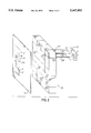
- FIG. 2, 2A and 3 further variations of the vending device according to the invention.
- FIG. 4 a block diagram to explain the access to the vending device according to the invention via a computing unit.
- a storage unit is marked with the reference numeral (2) in FIG. 1.
- compartments or containers that serve as receptacles for goods are arranged within the smallest possible space in this storage unit (2) that can be constructed in the most varied ways, as described later in the text, in such a way that they can be transported or conveyed to at least one withdrawal opening (4).
- withdrawal openings (4) can, for example, be arranged in a metal wall (3) closing one side of the storage unit (2) in such a way that the compartments or containers of the storage unit (2) can be arranged behind the withdrawal openings to load or withdraw goods onto/from the compartments.
- FIG. 1 schematically illustrates by broken lines that the storage unit (2) can, for example, be a device in which a transport apparatus (10) operating according to the elevator principle has several compartments (11) arranged in the Y-direction atop one other which extend as rows in X-direction on the side facing the metal wall (3) as well as on the side opposing the metal wall (3) in such a way that the compartments (11) of the individual rows can be moved behind the withdrawal openings (4) which can simultaneously serve as the loading openings.
- the compartments (11) are, for example, mounted in conventional manner to a schematically illustrated conveyor device (10'), for example, an endless conveyor belt or an endless chain conveyor, in such a way that they maintain a position in which their compartment openings are aligned horizontally during the rotation of the conveyor and that they point toward the metal wall (3) or a rear wall or another metal wall (6).
- the compartments (11) are, for example, retained on the conveyor (10) by arms (11') in such a way that they can be rotated around an axis (11") as schematically indicated for the lower left compartment (11).
- one of the withdrawal/loading openings (4) behind which an empty compartment (11) is located is displayed to the merchant in a manner described later in detail.
- the goods ordered by the customer can be placed into this compartment (11) by the merchant.
- the loaded compartment (11) is moved as desired within the storage unit (2) during subsequent withdrawal or loading operations after the door (4') has been locked.
- the door (4') is equipped with a locking device (not illustrated in the figure).
- a withdrawal/loading opening (4) is displayed to the customer in a manner described later in detail, whereby the compartment (11) containing the goods previously ordered by the customer is conveyed behind the withdrawal/loading opening by activating the conveyor device (10'). The customer can collect the desired goods after the respective door (4') is unlocked.
- doors (4') schematically illustrated in FIG. 1 can be all possible doors, flaps or other devices that can be opened after activating an unlocking device, for example, those swiveled about a hinge (not shown in the figure) or displaced in the plane of the metal wall (3) after activating the unlocking device in order to release the withdrawal/loading opening (4).
- FIG. 1 shows that the withdrawal and the loading of the compartments (11) can be executed through the openings (4) in the metal wall (3).
- the withdrawal can, for example, be executed as thus far described through the openings (4), while the loading is executed through openings (40) that can be located in the aforementioned metal wall (6) on the rear side of the storage unit (2).
- the vending device can be arranged in such a way that the loading is executed through the metal wall (6) from the store itself, while the withdrawal of the goods is executed outside the store through the metal wall (3).
- a shelf (5 or 5') can be arranged below the openings (4 or 40).
- the openings (4) as well as the openings (40) are arranged separately from each other in the metal wall (3).
- the openings (40) provided below the openings (4) are, for example, accessible from a basement room in order to be loaded by the merchant, while the openings (4) are accessible to the customer to withdraw the goods from a sales floor arranged above the basement.
- FIG. 1 it is also possible to provide any conceivable device that is able to move or transport one compartment of a number of compartments or one container of a number of containers behind at least one withdrawal/loading opening (4) by mechanical movements or transport processes.
- FIG. 2 shows that it is also possible to provided a shelf-like structure (20) behind the metal wall (3) as the storage unit, whereby containers (21) suitable to serve as receptacles for the goods ordered by the customer are arranged in the compartments (23) of the shelf-like structure.
- These containers (21) are grasped by the schematically illustrated gripping apparatus (22) of a transport device (25), removed from the shelf-like structure (20) (Z-direction) and moved to at least one withdrawal/loading opening (4) in the metal wall (3) in such a way (X- and Y-direction) that the container (21) arranged behind the withdrawal/loading opening (4) is accessible for withdrawal of the goods through the withdrawal/loading opening (4) after the door (4') is opened.
- the individual compartments (23) of the shelf-like structure (20) are preferably arranged in the form of rows (X-direction) and columns (Y-direction), so that each compartment (23) is accessible for the gripping device (22) by the coordinated movement of the transport device (25).
- This gripping device (22) is, for example, provided with a plate (22') that can be pushed under the container and is connected with the transport device (25) via retention rods (24) or similar elements.
- a loaded container (21) can thus be removed from a compartment (23) by moving the transport device (25) in the Z-direction, and an empty container (21) can be placed into a compartment (23).
- any arbitrary gripping devices (22) could be utilized by means of which the withdrawal of the container (21) from a compartment (23), its transport behind the area of the withdrawal/loading opening (4) and the return of the container (21) into a compartment (23) is possible.
- the device (20A) with the compartments (23A) for the containers in the form of a hollow cylinder, so that the compartments (23A) can be accessed by a gripping device (22A) that can be rotated around a central fulcrum (26) and raised and lowered in the Y-direction.
- At least one withdrawal/loading opening (4) is arranged in an outer metal wall (3A) that covers the hollow cylinder. If several openings (4) are provided, these openings are preferably arranged next to each other in the peripheral direction so that they can be accessed at one elevation during rotation of the gripping device.
- Such vending devices can have the shape of large vending silos.
- FIG. 3 shows that other devices in which the goods are stored in the compartments (32) of storage unit (30) are also conceivable.
- the goods are, for example, conveyed to a withdrawal opening (4) in a coordinated manner in order to withdraw them.
- the goods are, for example, placed manually into the compartments (32) of a cabinet-like storage unit (30), whereby certain goods are always arranged in certain compartments (32), the addresses or coordinates of which are known.
- the withdrawal device (31) can, for example, be displaced to each compartment for the withdrawal of goods in the X- and Y-directions by a mechanical transport device (33,34) (not described in detail).
- the withdrawal device (31) can receive certain goods from a predetermined compartment (32) by transfer to a container (35) assigned to it, and convey the container to a withdrawal opening (4) on the side of the storage unit (30) opposite to the container (35) arranged in a metal wall (3) at the location of the predetermined compartment (32), or reversely.
- FIGS. 1 and 3 show that operating elements, in particular an input device and display units are provided on the metal wall (3) by means of which the vending device according to the invention can be loaded with goods by a merchant, and by means of which a customer can empty the compartments (11) or containers (21) loaded for him by the merchant.
- the display unit can be, in particular, a monitor (7), as well as, possibly, lamps (12).
- the input device can, for example, be a slot (9) of a reading device and/or a keyboard (8).
- Such operation and display units as well as input devices are provided in the area of the withdrawal opening (4) as well as in the area of loading openings (40) if the withdrawal and loading openings (4,40) are arranged separately from each other.
- the elements provided on the metal wall (6) in FIG. 1 are marked with the reference numerals (7',8',9')
- a sale is in the following described in connection with FIG. 4.
- a customer who would like to obtain certain goods during times at which the store is closed places his order with a merchant that has access to the vending device according to the invention, preferably by telephone during normal business hours. It is practical if merchants of several different stores have access to the vending device so that a great variety of goods can be sold in the compartments (11) (FIG. 1).
- the merchant After the merchant has received the order, he collects the ordered goods and transports them to the loading opening (4 or 40) of the vending device according to the invention. He subsequently enters an identifying merchant code via the keyboard (8 or 8') or the slot (9 or 9') of the reading device.
- the merchant additionally enters the price of the ordered goods as well as an identifying customer number via the keyboard (8 or 8').
- the computing unit (50) checks the entered merchant code to determine if the merchant is authorized to load the compartment.
- the price entered via the keyboard (8 or 8') is assigned to a certain customer by the computing unit (50) based on the customer number entered by the merchant via the keyboard (8 or 8').
- the computing unit (50) subsequently determines a free compartment (11) and moves it behind one of the loading openings (4) by transmitting a control signal to the device (10).
- the computing unit Since the computing unit itself determines the free compartment (11), the respective compartment number or compartment address is always available to the computing unit.
- the selected opening (4) is displayed to the merchant on the monitor (7 or 7') or by illuminated display lamps (12 or 12') arranged above the corresponding compartment, or by any other arbitrary display unit.
- the computing unit (50) releases a display signal for this purpose.
- the unlocking device of the corresponding door (4' or 40') is simultaneously released by producing an unlocking signal in order to load the compartment.
- the merchant can now load the displayed compartment (11) by opening the door (4' or 40').
- the door is automatically locked after the loading of the compartment is concluded. This is preferably achieved by the fact that the locking device (not shown in the figures) automatically locks the door once more after a predetermined elapsed time, reckoned from the unlocking of the door.
- the merchant additionally enters the address or compartment number of the compartment (32) be reserved. All other processes are executed in the same manner as in FIG. 1.
- the customer During the withdrawal of the goods, the customer enters an identifying code that can, for example, be the account number and possibly a customer number into the computing unit via the keyboard (8) and/or the slot (9) of the reading device.
- the computing unit (50) checks if the customer is authorized to withdraw the goods based on the identification code stored in its memory.
- the device (10) subsequently conveys the compartment(s) (11) reserved for the customer behind one or more withdrawal openings (4) based on the control signals released by the computing unit (3).
- the corresponding withdrawal openings (4) are displayed to the customer on the monitor (7) or via illumination of the corresponding display lamps (12) or via the means of the other aforementioned elements.
- the corresponding doors (4') are simultaneously unlocked, so that the customer can withdrawal the goods placed into the compartments (11) by opening the door (4'). If the goods are issued through several doors (4'), the corresponding withdrawal openings (4) are preferably displayed successively by illumination of the display lamps (12) because a door (4') is automatically locked once more after a predetermined elapsed time, reckoned from the unlocking of the door. This means that at first only a first door (4') is displayed, and another door is subsequently unlocked and displayed after the first door was automatically locked and a locking signal was produced.
- a compartment (11) or a container (21) or several compartments or containers that contain the goods for the customer are successively conveyed to the withdrawal opening (4) by the transport device (25), so that the customer can withdraw the goods in the previously described manner.
- the sale is executed in the previously described manner if several openings (4) are provided.
- the duration between the withdrawal of goods from a compartment can be determined by the customer himself if a receipt key (29) is provided in the area of the withdrawal opening (4). After the customer withdraws the goods from a compartment, he activates the receipt key (29) to produce a receipt signal. Once a receipt signal and the locking signal produced when the compartment is closed are present, the computing unit (50) causes the transport device (10,25,25A,35) to move and the goods to be conveyed to the same opening or a different opening (4) which is displayed to the customer.
- the doors (4' or 40') automatically return into their closing position after they are released by the customer or the merchant, so that the least possible amount of cold air can escape from the storage unit.
- the computing unit (50) contains a so-called conversion table that makes the address coordination possible based on the offset between of the withdrawal openings (4) and the loading openings (40').
- the storage units are devices with a shelf-like structure and of large capacity (FIGS. 2, 2A, 3) or large silos (FIG. 2A).
- the loading of these storage units with goods or the withdrawal of goods from these storage units is executed through one or relatively few withdrawal/loading openings that require little sales space in a wall or similar structure and can be easily operated by the customer or merchant.
- This invention represents the first instance in which the idea of a number of compartments with doors according to the known vending system has been abolished, and the assignment of only one or few withdrawal/loading openings to a large number of compartments and their access in a specialized manner via the computing unit is implemented in its place.
- vending device in the described manner to withdraw the goods, and to perform the loading of the goods in a different manner. It is, for example, possible to introduce the goods directly into the compartments instead of through the openings (4 or 40).
Abstract
Description
Claims (8)
Priority Applications (1)
| Application Number | Priority Date | Filing Date | Title |
|---|---|---|---|
| US08/304,033 US5467892A (en) | 1992-01-31 | 1994-09-09 | Vending device |
Applications Claiming Priority (4)
| Application Number | Priority Date | Filing Date | Title |
|---|---|---|---|
| DE4202801A DE4202801C2 (en) | 1992-01-31 | 1992-01-31 | Sales facility |
| DE4202801.9 | 1992-01-31 | ||
| US08/010,934 US5385265A (en) | 1992-01-31 | 1993-01-29 | Vending device |
| US08/304,033 US5467892A (en) | 1992-01-31 | 1994-09-09 | Vending device |
Related Parent Applications (1)
| Application Number | Title | Priority Date | Filing Date |
|---|---|---|---|
| US08/010,934 Division US5385265A (en) | 1992-01-31 | 1993-01-29 | Vending device |
Publications (1)
| Publication Number | Publication Date |
|---|---|
| US5467892A true US5467892A (en) | 1995-11-21 |
Family
ID=6450705
Family Applications (2)
| Application Number | Title | Priority Date | Filing Date |
|---|---|---|---|
| US08/010,934 Expired - Lifetime US5385265A (en) | 1992-01-31 | 1993-01-29 | Vending device |
| US08/304,033 Expired - Lifetime US5467892A (en) | 1992-01-31 | 1994-09-09 | Vending device |
Family Applications Before (1)
| Application Number | Title | Priority Date | Filing Date |
|---|---|---|---|
| US08/010,934 Expired - Lifetime US5385265A (en) | 1992-01-31 | 1993-01-29 | Vending device |
Country Status (3)
| Country | Link |
|---|---|
| US (2) | US5385265A (en) |
| EP (1) | EP0553470A1 (en) |
| DE (1) | DE4202801C2 (en) |
Cited By (49)
| Publication number | Priority date | Publication date | Assignee | Title |
|---|---|---|---|---|
| US6264104B1 (en) | 1994-03-21 | 2001-07-24 | Imaging Technologies Pty Limited | Vending device with remote electronic shopping facility |
| US6404337B1 (en) | 1999-10-28 | 2002-06-11 | Brivo Systems, Inc. | System and method for providing access to an unattended storage |
| US6426699B1 (en) | 1998-12-02 | 2002-07-30 | David Porter | Collapsible storage device for the delivery and pickup of goods |
| US20030143445A1 (en) * | 2002-01-25 | 2003-07-31 | Daniel Michael J. | Apparatus and method for operating a fuel reformer to provide reformate gas to both a fuel cell and an emission abatement device |
| US20030232760A1 (en) * | 2001-09-21 | 2003-12-18 | Merck & Co., Inc. | Conjugates useful in the treatment of prostate cancer |
| WO2004027720A2 (en) * | 2002-09-17 | 2004-04-01 | Gordon Jurgenson | Subterainian vending machine with conveyor delivery |
| US6748295B2 (en) | 2000-07-26 | 2004-06-08 | Northrop Grumman Corporation | Item delivery and retrieval system |
| US20040254676A1 (en) * | 2003-06-11 | 2004-12-16 | Touch Automation | Automated business system and method of vending and returning a consumer product |
| US20050056577A1 (en) * | 2003-09-03 | 2005-03-17 | Siemens Aktiengesells Chaft | System and method for item handling |
| FR2864672A1 (en) * | 2003-12-31 | 2005-07-01 | Letsact | Fresh product e.g. French loaf, distributing installation for railway station, has rack with compartments having opening to withdraw product, and control device to activate ticket reader/signaling unit based on information given by reader |
| ES2245541A1 (en) * | 2003-02-18 | 2006-01-01 | Española De Intermediacion De Seguridad, S.L. | Storage and control furniture for audiovisual products, has carousels, which carry receivers for audio visual products, arranged at different levels within prismatic body and constructed of chains geared with crowns at ends |
| US20070108222A1 (en) * | 2005-10-14 | 2007-05-17 | Collins Bryan A | Product transport system for a vending machine |
| US7234609B2 (en) | 2004-04-15 | 2007-06-26 | Redbox Automated Retail, L.L.C. | Article dispensing system and method for same |
| US20070187423A1 (en) * | 2006-02-10 | 2007-08-16 | Cerner Innovation, Inc. | Apparatus for dispensing medications |
| US20070187424A1 (en) * | 2006-02-10 | 2007-08-16 | Cerner Innovation, Inc. | Method for dispensing medications |
| US20080015733A1 (en) * | 2006-07-05 | 2008-01-17 | Timothy Robey | Position indicator apparatus and method |
| US7451892B2 (en) * | 1997-03-21 | 2008-11-18 | Walker Digital, Llc | Vending machine system and method for encouraging the purchase of profitable items |
| US7451891B2 (en) | 2004-02-27 | 2008-11-18 | Sandenvendo America, Inc. | Vending machine and component parts |
| US20090143902A1 (en) * | 2004-06-11 | 2009-06-04 | Donald Blust | Automated business system and method of vending and returning a consumer product |
| US20090140000A1 (en) * | 2007-11-30 | 2009-06-04 | Davis Jr Clifford H | Dispensing apparatus system and method |
| US20090192837A1 (en) * | 2008-01-24 | 2009-07-30 | John Wesley Templer | Dispensing Consumer Products |
| US20100017021A1 (en) * | 2005-07-02 | 2010-01-21 | Syngenta Participations Ag | Apparatus and method for coordinating automated package and bulk dispensing |
| US7711658B2 (en) | 1997-10-09 | 2010-05-04 | Walker Digital, Llc | Method and apparatus for dynamically managing vending machine inventory prices |
| US20100108711A1 (en) * | 2005-07-02 | 2010-05-06 | Syngenta Participations Ag | Apparatuses and methods for bulk dispensing |
| US7747346B2 (en) | 2005-04-22 | 2010-06-29 | Redbox Automated Retail, Llc | System and method for regulating vendible media products |
| US7837059B2 (en) | 2004-02-27 | 2010-11-23 | Sanden Vendo America, Inc. | Product acquisition devices and methods for vending machines |
| US7894936B2 (en) | 1997-10-09 | 2011-02-22 | Walker Digital, Llc | Products and processes for managing the prices of vending machine inventory |
| US20110060693A1 (en) * | 2009-09-09 | 2011-03-10 | Sanden Vendo America, Inc. | Vending Machine for Large Product Containers |
| US8060247B2 (en) | 2005-04-22 | 2011-11-15 | Redbox Automated Retail, Llc | System and method for communicating secondary vending options |
| ES2373904A1 (en) * | 2011-08-05 | 2012-02-10 | Francisco Javier Cruz Abreu | System of dispensation of articles of vending machines. (Machine-translation by Google Translate, not legally binding) |
| US8162174B2 (en) | 2004-02-27 | 2012-04-24 | Sandenvendo America, Inc. | Retrieval systems for vending machines |
| US8538581B2 (en) | 2010-09-03 | 2013-09-17 | Redbox Automated Retail, Llc | Article vending machine and method for authenticating received articles |
| US8712872B2 (en) | 2012-03-07 | 2014-04-29 | Redbox Automated Retail, Llc | System and method for optimizing utilization of inventory space for dispensable articles |
| US8768789B2 (en) | 2012-03-07 | 2014-07-01 | Redbox Automated Retail, Llc | System and method for optimizing utilization of inventory space for dispensable articles |
| US8996162B2 (en) | 2009-09-05 | 2015-03-31 | Redbox Automated Retail, Llc | Article vending machine and method for exchanging an inoperable article for an operable article |
| US9104990B2 (en) | 2009-09-05 | 2015-08-11 | Redbox Automated Retail, Llc | Article vending machine and method for exchanging an inoperable article for an operable article |
| US9171316B2 (en) | 1997-08-26 | 2015-10-27 | Inventor Holdings, Llc | Method and apparatus for vending a combination of products |
| WO2015197903A1 (en) * | 2014-06-26 | 2015-12-30 | Benito Manuel Ortiz Padilla | Automated system for storing personal items |
| US9286617B2 (en) | 2011-08-12 | 2016-03-15 | Redbox Automated Retail, Llc | System and method for applying parental control limits from content providers to media content |
| US9348822B2 (en) | 2011-08-02 | 2016-05-24 | Redbox Automated Retail, Llc | System and method for generating notifications related to new media |
| US9495465B2 (en) | 2011-07-20 | 2016-11-15 | Redbox Automated Retail, Llc | System and method for providing the identification of geographically closest article dispensing machines |
| ITUB20153030A1 (en) * | 2015-08-10 | 2017-02-10 | Bm S P A | APPARATUS FOR TEMPORARY STORAGE OF OBJECTS. |
| US9569911B2 (en) | 2010-08-23 | 2017-02-14 | Redbox Automated Retail, Llc | Secondary media return system and method |
| US9747253B2 (en) | 2012-06-05 | 2017-08-29 | Redbox Automated Retail, Llc | System and method for simultaneous article retrieval and transaction validation |
| US9785996B2 (en) | 2011-06-14 | 2017-10-10 | Redbox Automated Retail, Llc | System and method for substituting a media article with alternative media |
| FR3052963A1 (en) * | 2016-06-28 | 2017-12-29 | Nestore Green Tech | DISTRIBUTOR OF GOODS |
| US10373223B2 (en) | 2012-11-12 | 2019-08-06 | Restaurant Technology Inc. | System and method for receiving and managing remotely placed orders |
| US10640357B2 (en) | 2010-04-14 | 2020-05-05 | Restaurant Technology Inc. | Structural food preparation systems and methods |
| US10810822B2 (en) | 2007-09-28 | 2020-10-20 | Redbox Automated Retail, Llc | Article dispensing machine and method for auditing inventory while article dispensing machine remains operable |
Families Citing this family (105)
| Publication number | Priority date | Publication date | Assignee | Title |
|---|---|---|---|---|
| US5638985A (en) * | 1995-01-11 | 1997-06-17 | Design & Manufacturing Services, Inc. | Vending apparatus and method |
| GB2302976A (en) * | 1995-06-30 | 1997-02-05 | Peter Douglas White | Security method and apparatus |
| US5780842A (en) * | 1996-04-10 | 1998-07-14 | Murphey; James D. | Item dispensing control system for use in vending devices |
| US5845808A (en) * | 1997-05-20 | 1998-12-08 | Nikko Confectionery Co., Ltd. | Disposable sterilized fluid container |
| DE19728885C2 (en) * | 1997-07-07 | 2000-10-19 | Reinhard Albers | Computer-based loan system |
| US6230930B1 (en) * | 1997-10-14 | 2001-05-15 | Cross-Given Manufacturing Company | Apparatus and method for vending products |
| US6513677B1 (en) | 1997-10-14 | 2003-02-04 | Gross-Given Manufacturing Company | Apparatus and method for vending products |
| US6283780B1 (en) | 1998-04-01 | 2001-09-04 | Molex Incorporated | Test socket lattice |
| US6267603B1 (en) | 1998-04-01 | 2001-07-31 | Molex Incorporated | Burn-in test socket |
| USD430423S (en) * | 1999-01-19 | 2000-09-05 | Santa Fe Natural Tobacco Company, Inc. | Merchandise display |
| USD431931S (en) * | 1999-01-19 | 2000-10-17 | Santa Fe Natural Tobacco Company, Inc. | Merchandise display |
| US6330856B1 (en) | 1999-01-28 | 2001-12-18 | Innovative Product Achievements, Inc. | Garment dispensing and receiving apparatus |
| US6464142B1 (en) * | 1999-10-29 | 2002-10-15 | Si/Baker, Inc. | Automated will call system |
| DE19952984A1 (en) * | 1999-11-03 | 2001-05-23 | Wincor Nixdorf Gmbh & Co Kg | Locker arrangement for storing and depositing items |
| JP2001160176A (en) * | 1999-12-03 | 2001-06-12 | Sanden Corp | Automatic vending machine |
| US6223934B1 (en) | 2000-01-18 | 2001-05-01 | S&S X-Ray Products, Inc. | Scrub dispensing cabinet |
| EP1120756B1 (en) * | 2000-01-28 | 2007-02-14 | Societe Des Produits Nestle S.A. | Mechanism for product delivered in automatic vending machines and tamper-resistant vending machine |
| EP1489564A3 (en) * | 2000-02-07 | 2005-01-19 | FKI Logistex A/S | A method of delivering items from an item delivery system |
| JP2001241225A (en) * | 2000-02-28 | 2001-09-04 | Full Time System:Kk | Specific unlocking system for locker |
| IL134828A0 (en) * | 2000-03-01 | 2001-05-20 | Eship 4U Com Inc | System for delivery and receipt of dispatches especially useful for e-commerce |
| DE10022935A1 (en) * | 2000-05-11 | 2001-11-15 | Olaf Berberich | Control system for lockers or safety deposit boxes |
| US6892941B2 (en) | 2000-06-08 | 2005-05-17 | Mendota Healthcare, Inc. | Automatic prescription drug dispenser |
| AU2001290661A1 (en) * | 2000-09-06 | 2002-03-22 | Advanced Pharmacy Technologies, L.L.C. | Automated prescription dispensing system and method of use |
| WO2002063578A1 (en) * | 2001-02-06 | 2002-08-15 | Societe Des Produits Nestle S.A. | Mechanism for product delivered in automatic vending machines and tamper-resistant vending machine |
| US6694217B2 (en) * | 2001-05-24 | 2004-02-17 | Breakthrough Logistics Corporation | Automated system for efficient article storage and self-service retrieval |
| AU2002257055A1 (en) * | 2001-03-16 | 2002-10-03 | Gregg Bloom | Automated system for efficient article storage and self-service retrieval |
| US6502718B2 (en) | 2001-03-19 | 2003-01-07 | Innovative Product Achievements, Inc. | Garment dispensing and receiving apparatus having a removable cartridge body and a flexible dispensing door |
| FR2828756B1 (en) * | 2001-08-16 | 2003-12-12 | Rb Concept | AUTOMATIC GAS BOTTLE DISPENSER |
| US6690997B2 (en) * | 2001-09-13 | 2004-02-10 | M.A. Rivalto, Inc. | System for automated package-pick up and delivery |
| US6971541B2 (en) | 2002-05-14 | 2005-12-06 | Parata Systems, Inc. | System and method for dispensing prescriptions |
| PT1520261E (en) * | 2002-07-05 | 2007-02-28 | Crane Co | Apparatus and method for vending products having various dimensions |
| US7032776B2 (en) * | 2002-08-08 | 2006-04-25 | The Vendo Company | Vending machine bucket drive control |
| US7303094B2 (en) | 2002-08-09 | 2007-12-04 | Kevin Hutchinson | Vacuum pill dispensing cassette and counting machine |
| US7228198B2 (en) | 2002-08-09 | 2007-06-05 | Mckesson Automation Systems, Inc. | Prescription filling apparatus implementing a pick and place method |
| JP2004318829A (en) * | 2003-03-28 | 2004-11-11 | Sanden Corp | Vending machine |
| US20040245272A1 (en) * | 2003-04-15 | 2004-12-09 | Innovative Product Achievements, Inc. | Compact dispenser with flexible door |
| US20040206462A1 (en) * | 2003-04-15 | 2004-10-21 | Innovative Product Achievements, Inc. | Reduced friction flexible door |
| AT500112B8 (en) * | 2003-06-20 | 2007-02-15 | Keba Ag | STORAGE MACHINE FOR OBJECTS |
| US7123989B2 (en) * | 2003-07-01 | 2006-10-17 | Asteres, Inc. | System and method for providing a random access and random load dispensing unit |
| US20050192705A1 (en) | 2003-07-01 | 2005-09-01 | Asteres Inc. | Random access and random load dispensing unit |
| EP1644250B1 (en) * | 2003-07-01 | 2012-12-05 | Asteres Inc. | Random access and random load dispensing unit |
| US20050049746A1 (en) * | 2003-08-26 | 2005-03-03 | Ken Rosenblum | Automatic prescription drug dispenser |
| US7447605B2 (en) * | 2004-04-15 | 2008-11-04 | Redbox Automated Retail, Llc | System and method for calibrating a vending apparatus |
| US7584869B2 (en) * | 2004-04-15 | 2009-09-08 | Redbox Automated Retail, Llc | Article dispensing system and method for same |
| US7228200B2 (en) * | 2004-04-22 | 2007-06-05 | Parata Systems, Llc | Apparatus, system and methods for dispensing products |
| US8121725B2 (en) * | 2004-04-22 | 2012-02-21 | Parata Systems, Llc | Apparatus, system and methods for dispensing products |
| AT500304B1 (en) * | 2004-05-14 | 2006-11-15 | Keba Ag | STORAGE MACHINE FOR OBJECTS |
| CN101057264B (en) * | 2004-09-21 | 2010-07-07 | Keba股份公司 | Automatic storage machine for objects |
| US7194333B2 (en) * | 2004-11-24 | 2007-03-20 | S & S X-Ray Products, Inc. | Pharmacy envelope dispensing arrangement |
| FR2888379A1 (en) * | 2005-07-05 | 2007-01-12 | Ali Messaoudi | Article e.g. water bottle, payment time reducing method for supermarket, involves allowing operator to record articles disposed in bags that are transferred via tunnel towards receptacles having ticket restitution and card payment units |
| AT8094U3 (en) * | 2005-08-29 | 2006-09-15 | Keba Ag | STORAGE MACHINE FOR OBJECTS |
| US20110044792A1 (en) * | 2005-08-30 | 2011-02-24 | Talley Paul A | Facility And Method For Interment And Automated Retrieval Of Interred Subjects |
| US20070065259A1 (en) * | 2005-08-30 | 2007-03-22 | Talley Paul A | Automated self storage system |
| US20070151981A1 (en) * | 2005-09-27 | 2007-07-05 | Leonard Halsey | Firewood dispenser |
| US20070187485A1 (en) | 2006-02-10 | 2007-08-16 | Aas Per C | Cash handling |
| US20070240631A1 (en) * | 2006-04-14 | 2007-10-18 | Applied Materials, Inc. | Epitaxial growth of compound nitride semiconductor structures |
| US7809470B2 (en) * | 2006-11-28 | 2010-10-05 | S & S X-Ray Products, Inc. | Controlled access supply cabinet and system |
| FR2914088B1 (en) * | 2007-03-21 | 2009-05-22 | Thierry Chapon | PHARMACEUTICAL OR PARAPHARMACEUTICAL PRODUCT MANAGEMENT ASSEMBLY |
| US7783379B2 (en) * | 2007-04-25 | 2010-08-24 | Asteres, Inc. | Automated vending of products containing controlled substances |
| US9245406B2 (en) | 2007-05-04 | 2016-01-26 | Innovative Product Achievements, Llc | Apparatus for inserting a cart, such as a cart with one or more fixed wheels, into an enclosure |
| DE102007040863B4 (en) | 2007-08-29 | 2010-07-29 | Hänel & Co. | Storage rack with transport device |
| US8123071B2 (en) * | 2007-09-28 | 2012-02-28 | Innovative Product Acheivements, LLC | Methods and apparatus for increasing the speed of dispensing articles from vending machines |
| US20090120760A1 (en) * | 2007-11-12 | 2009-05-14 | Anders Sjostrom | Dual use coin deposit and dispensing apparatus |
| US20090178598A1 (en) * | 2008-01-16 | 2009-07-16 | Scott Meeker | Centralized electronic safe and accounting control system including configurable deposit and cash dispensing authority and armored car transaction automation |
| US20090259557A1 (en) * | 2008-04-08 | 2009-10-15 | Restaurant Technology, Inc. | System and method for enhanced customer kiosk ordering |
| US9280863B2 (en) * | 2008-07-16 | 2016-03-08 | Parata Systems, Llc | Automated dispensing system for pharmaceuticals and other medical items |
| US20110047010A1 (en) * | 2009-08-21 | 2011-02-24 | Redbox Automated Retail, Llc | Article vending machine and method for receiving restricted discount codes |
| CA2819864C (en) | 2010-12-08 | 2019-01-08 | Apex Industrial Technologies Llc | Direct access dispensing system |
| US8160741B1 (en) * | 2010-12-15 | 2012-04-17 | S&S X-Ray Products, Inc. | Pass-through wall-mounted medications cabinet and system |
| CA2923342C (en) | 2011-12-05 | 2019-08-20 | United States Postal Service | A system and method of control of electronic parcel lockers |
| US9478093B2 (en) | 2012-02-15 | 2016-10-25 | Innovative Product Achievements, Llc | Item dispensing apparatus |
| US9208635B2 (en) | 2012-09-28 | 2015-12-08 | Innovative Product Achievements, Llc | Item dispensing apparatus |
| US20180372398A1 (en) * | 2013-04-23 | 2018-12-27 | Minibar North America, Inc. | Controlled inventory refrigerated dispensing system |
| US9378607B1 (en) * | 2013-05-14 | 2016-06-28 | IVP Holdings III LLC | Dynamic product presentation system and commerce platform |
| US20150120601A1 (en) * | 2013-10-25 | 2015-04-30 | Florence Manufacturing Company | Electronically controlled parcel delivery system |
| US9990684B2 (en) * | 2014-05-01 | 2018-06-05 | Sammy Hejazi | Mailport for automated parcel carriers |
| US10074068B2 (en) | 2014-06-20 | 2018-09-11 | United States Postal Service | Systems and methods for control of electronic parcel lockers |
| US9135403B1 (en) * | 2014-07-29 | 2015-09-15 | John Tolmosoff | Apparatus and method for storing and dispensing pharmacist-filled prescription medications |
| DE102014113045B4 (en) * | 2014-09-10 | 2022-03-03 | Hartmut Lang | Defect dispenser |
| US20180268358A1 (en) * | 2015-01-09 | 2018-09-20 | Apex Industrial Technologies Llc | Order fulfillment system and method with item sensor |
| US10216157B2 (en) * | 2015-01-09 | 2019-02-26 | Apex Industrial Technologies Llc | Order fulfillment system and method |
| WO2016126723A1 (en) | 2015-02-02 | 2016-08-11 | Innovative Product Achievements, Llc | Item dispensing apparatus |
| FI20155359L (en) * | 2015-05-18 | 2016-11-19 | Pickdelso Oy | System, trolley and method for storing products |
| US10592843B2 (en) * | 2015-11-25 | 2020-03-17 | Walmart Apollo, Llc | Unmanned aerial delivery to secure location |
| CA3018585A1 (en) | 2016-03-23 | 2017-09-28 | United States Postal Service | Receptacle for detecting delivery and retrieval events |
| US11120390B2 (en) | 2016-08-12 | 2021-09-14 | United States Postal Service | Smart drop box |
| WO2018067327A1 (en) | 2016-10-04 | 2018-04-12 | Wal-Mart Stores, Inc. | Landing pad receptacle for package delivery and receipt |
| US11068837B2 (en) * | 2016-11-21 | 2021-07-20 | International Business Machines Corporation | System and method of securely sending and receiving packages via drones |
| US20180170673A1 (en) * | 2016-12-16 | 2018-06-21 | David Seeley | Systems and methods for multi-unit dwelling storage |
| IT201600132286A1 (en) * | 2016-12-29 | 2018-06-29 | Gav Sistemi Srl | EQUIPMENT SUPPLY DEVICE FOR ASSEMBLY |
| FR3063372B1 (en) | 2017-02-27 | 2019-03-29 | Savoye | AUTOMATIC SETTING DEVICE AND CORRESPONDING DISTRIBUTION AND INSERTION METHODS. |
| JP2018201643A (en) * | 2017-05-31 | 2018-12-27 | 大和ハウス工業株式会社 | Home delivery box device |
| TW201909065A (en) | 2017-07-14 | 2019-03-01 | 美商促美股份有限公司 | System and method for selling and or preparing articles based on kiosks, for example, preparing food |
| US11270251B2 (en) | 2017-10-16 | 2022-03-08 | Florence Corporation | Package management system with accelerated delivery |
| US10643415B2 (en) | 2017-10-16 | 2020-05-05 | Florence Corporation | Package management system with accelerated delivery |
| US10915856B2 (en) | 2017-10-16 | 2021-02-09 | Florence Corporation | Package management system with accelerated delivery |
| US11144873B2 (en) | 2017-10-16 | 2021-10-12 | Florence Corporation | Package management system with accelerated delivery |
| CN109993890B (en) * | 2017-12-29 | 2020-05-22 | 山东新北洋信息技术股份有限公司 | Vending machine and goods channel height detection method |
| US11410118B2 (en) | 2018-06-01 | 2022-08-09 | Florence Corporation | Package management system |
| CA3109226A1 (en) | 2018-08-21 | 2020-02-27 | Florence Corporation | Purchased item management and promotional systems and methods |
| USD954481S1 (en) | 2019-12-13 | 2022-06-14 | Florence Corporation | Double walled locker door |
| US11529011B2 (en) | 2019-06-11 | 2022-12-20 | Florence Corporation | Package delivery receptacle and method of use |
| EP3989143A1 (en) * | 2020-10-26 | 2022-04-27 | Viabirds Technologies GmbH | System and pick-up station for providing goods |
| CA3205364A1 (en) * | 2021-01-18 | 2022-07-21 | Robert F. Cotter | Automated dispenser for garments and other articles and associated methods |
| AT17745U3 (en) * | 2022-06-09 | 2023-04-15 | Burgstaller Peter | vending machine |
Citations (15)
| Publication number | Priority date | Publication date | Assignee | Title |
|---|---|---|---|---|
| US2313424A (en) * | 1939-08-17 | 1943-03-09 | Charles Arthur Jean | Registering key for dispensing apparatus |
| US3128013A (en) * | 1961-04-07 | 1964-04-07 | Universal Match Corp | Vending machine |
| US3164294A (en) * | 1963-01-21 | 1965-01-05 | Lektro Vend Corp | Electrically operated merchandise vending machine |
| FR2306021A1 (en) * | 1975-04-03 | 1976-10-29 | Redoute | Separate item distribution system - has numbered compartments travelling past reference number and stopped on coincidence |
| FR2343521A2 (en) * | 1975-04-03 | 1977-10-07 | Redoute | Dispensing mechanism for automatic vending machine |
| FR2563985A1 (en) * | 1984-05-14 | 1985-11-15 | Gille Pierre | Automatic cassette dispensing device, in particular for video cassettes |
| US4560088A (en) * | 1984-05-11 | 1985-12-24 | Tan Larry K | Vending machine with dispensing operating system movable in X-Y coordinate axes |
| EP0234833A2 (en) * | 1986-02-14 | 1987-09-02 | Samuel Sabbagh | A vending and dispensing system |
| WO1988002524A1 (en) * | 1986-09-25 | 1988-04-07 | Essex Engineering Company | Automatic rental vending machine |
| US4812629A (en) * | 1985-03-06 | 1989-03-14 | Term-Tronics, Incorporated | Method and apparatus for vending |
| FR2643479A1 (en) * | 1989-02-22 | 1990-08-24 | Normand Jean | Method of parcel distribution in an urban environment and device for implementing this method |
| US4961507A (en) * | 1986-11-19 | 1990-10-09 | Higgins Larry G | Dispensing system for handling consumable tooling and supplies |
| DE3914686A1 (en) * | 1989-05-03 | 1991-03-07 | Accumulata Verwaltungs Gmbh | SALES SYSTEM |
| US5088586A (en) * | 1987-04-30 | 1992-02-18 | Oki Electric Industry Co., Ltd. | Automatic renting apparatus |
| US5169027A (en) * | 1987-10-26 | 1992-12-08 | Unidynamics Corporation | Multiple-product merchandising machine |
Family Cites Families (2)
| Publication number | Priority date | Publication date | Assignee | Title |
|---|---|---|---|---|
| DE3314189A1 (en) * | 1982-04-21 | 1983-10-27 | Jürgen-Clemens 5500 Trier Clüsserath | Vending machine for small parts, especially for the delivery of electronic components |
| DE3530188A1 (en) * | 1985-08-23 | 1987-03-05 | Johannes Zidek | Automatic rental machine for electronically identifiable articles, especially video-tape cassettes |
-
1992
- 1992-01-31 DE DE4202801A patent/DE4202801C2/en not_active Expired - Fee Related
- 1992-12-17 EP EP92121512A patent/EP0553470A1/en not_active Ceased
-
1993
- 1993-01-29 US US08/010,934 patent/US5385265A/en not_active Expired - Lifetime
-
1994
- 1994-09-09 US US08/304,033 patent/US5467892A/en not_active Expired - Lifetime
Patent Citations (15)
| Publication number | Priority date | Publication date | Assignee | Title |
|---|---|---|---|---|
| US2313424A (en) * | 1939-08-17 | 1943-03-09 | Charles Arthur Jean | Registering key for dispensing apparatus |
| US3128013A (en) * | 1961-04-07 | 1964-04-07 | Universal Match Corp | Vending machine |
| US3164294A (en) * | 1963-01-21 | 1965-01-05 | Lektro Vend Corp | Electrically operated merchandise vending machine |
| FR2306021A1 (en) * | 1975-04-03 | 1976-10-29 | Redoute | Separate item distribution system - has numbered compartments travelling past reference number and stopped on coincidence |
| FR2343521A2 (en) * | 1975-04-03 | 1977-10-07 | Redoute | Dispensing mechanism for automatic vending machine |
| US4560088A (en) * | 1984-05-11 | 1985-12-24 | Tan Larry K | Vending machine with dispensing operating system movable in X-Y coordinate axes |
| FR2563985A1 (en) * | 1984-05-14 | 1985-11-15 | Gille Pierre | Automatic cassette dispensing device, in particular for video cassettes |
| US4812629A (en) * | 1985-03-06 | 1989-03-14 | Term-Tronics, Incorporated | Method and apparatus for vending |
| EP0234833A2 (en) * | 1986-02-14 | 1987-09-02 | Samuel Sabbagh | A vending and dispensing system |
| WO1988002524A1 (en) * | 1986-09-25 | 1988-04-07 | Essex Engineering Company | Automatic rental vending machine |
| US4961507A (en) * | 1986-11-19 | 1990-10-09 | Higgins Larry G | Dispensing system for handling consumable tooling and supplies |
| US5088586A (en) * | 1987-04-30 | 1992-02-18 | Oki Electric Industry Co., Ltd. | Automatic renting apparatus |
| US5169027A (en) * | 1987-10-26 | 1992-12-08 | Unidynamics Corporation | Multiple-product merchandising machine |
| FR2643479A1 (en) * | 1989-02-22 | 1990-08-24 | Normand Jean | Method of parcel distribution in an urban environment and device for implementing this method |
| DE3914686A1 (en) * | 1989-05-03 | 1991-03-07 | Accumulata Verwaltungs Gmbh | SALES SYSTEM |
Cited By (100)
| Publication number | Priority date | Publication date | Assignee | Title |
|---|---|---|---|---|
| US6264104B1 (en) | 1994-03-21 | 2001-07-24 | Imaging Technologies Pty Limited | Vending device with remote electronic shopping facility |
| US7885726B2 (en) | 1997-03-21 | 2011-02-08 | Walker Digital, Llc | Vending machine system and method for encouraging the purchase of profitable items |
| US7451892B2 (en) * | 1997-03-21 | 2008-11-18 | Walker Digital, Llc | Vending machine system and method for encouraging the purchase of profitable items |
| US9171316B2 (en) | 1997-08-26 | 2015-10-27 | Inventor Holdings, Llc | Method and apparatus for vending a combination of products |
| US7894936B2 (en) | 1997-10-09 | 2011-02-22 | Walker Digital, Llc | Products and processes for managing the prices of vending machine inventory |
| US7711658B2 (en) | 1997-10-09 | 2010-05-04 | Walker Digital, Llc | Method and apparatus for dynamically managing vending machine inventory prices |
| US6426699B1 (en) | 1998-12-02 | 2002-07-30 | David Porter | Collapsible storage device for the delivery and pickup of goods |
| US6404337B1 (en) | 1999-10-28 | 2002-06-11 | Brivo Systems, Inc. | System and method for providing access to an unattended storage |
| US6748295B2 (en) | 2000-07-26 | 2004-06-08 | Northrop Grumman Corporation | Item delivery and retrieval system |
| US20040193314A1 (en) * | 2000-07-26 | 2004-09-30 | Northrop Grumman Corporation | Item delivery and retrieval system |
| US7133743B2 (en) | 2000-07-26 | 2006-11-07 | Northrop Grumman Corporation | Item delivery and retrieval system |
| US20030232760A1 (en) * | 2001-09-21 | 2003-12-18 | Merck & Co., Inc. | Conjugates useful in the treatment of prostate cancer |
| US20030143445A1 (en) * | 2002-01-25 | 2003-07-31 | Daniel Michael J. | Apparatus and method for operating a fuel reformer to provide reformate gas to both a fuel cell and an emission abatement device |
| WO2004027720A3 (en) * | 2002-09-17 | 2004-08-12 | Gordon Jurgenson | Subterainian vending machine with conveyor delivery |
| WO2004027720A2 (en) * | 2002-09-17 | 2004-04-01 | Gordon Jurgenson | Subterainian vending machine with conveyor delivery |
| ES2245541A1 (en) * | 2003-02-18 | 2006-01-01 | Española De Intermediacion De Seguridad, S.L. | Storage and control furniture for audiovisual products, has carousels, which carry receivers for audio visual products, arranged at different levels within prismatic body and constructed of chains geared with crowns at ends |
| US8041454B2 (en) | 2003-06-11 | 2011-10-18 | Ncr Corporation | Automated business system and method of vending and returning a consumer product |
| US8078316B2 (en) | 2003-06-11 | 2011-12-13 | Ncr Corporation | Automated business system and method of vending and returning a consumer product |
| US20070169132A1 (en) * | 2003-06-11 | 2007-07-19 | Touch Automation | Automated business system and method of vending and returning a consumer product |
| US9646451B2 (en) | 2003-06-11 | 2017-05-09 | Ncr Corporation | Automated business system and method of vending and returning a consumer product |
| US8086349B2 (en) | 2003-06-11 | 2011-12-27 | Ncr Corporation | Automated business system and method of vending and returning a consumer product |
| US20090143905A1 (en) * | 2003-06-11 | 2009-06-04 | Donald Blust | Automated business system and method of vending and returning a consumer product |
| US20110184554A9 (en) * | 2003-06-11 | 2011-07-28 | Donald Blust | Automated business system and method of vending and returning a consumer product |
| US20090139999A1 (en) * | 2003-06-11 | 2009-06-04 | Donald Blust | Automated business system and method of vending and returning a consumer product |
| US20090143901A1 (en) * | 2003-06-11 | 2009-06-04 | Donald Blust | Automated business system and method of vending and returning a consumer product |
| US20040254676A1 (en) * | 2003-06-11 | 2004-12-16 | Touch Automation | Automated business system and method of vending and returning a consumer product |
| US20050056577A1 (en) * | 2003-09-03 | 2005-03-17 | Siemens Aktiengesells Chaft | System and method for item handling |
| US20070108110A1 (en) * | 2003-09-03 | 2007-05-17 | Siemens Aktiengesellschaft | System and method for item handling |
| US7159722B2 (en) | 2003-09-03 | 2007-01-09 | Siemens Ag | System and method for item handling |
| FR2864672A1 (en) * | 2003-12-31 | 2005-07-01 | Letsact | Fresh product e.g. French loaf, distributing installation for railway station, has rack with compartments having opening to withdraw product, and control device to activate ticket reader/signaling unit based on information given by reader |
| US7886930B2 (en) | 2004-02-27 | 2011-02-15 | Sandenvendo America, Inc. | Modular cabinet for vending machines |
| US7823750B2 (en) | 2004-02-27 | 2010-11-02 | Sanden Vendo America, Inc. | Product delivery systems for vending machines |
| US8162174B2 (en) | 2004-02-27 | 2012-04-24 | Sandenvendo America, Inc. | Retrieval systems for vending machines |
| US7451891B2 (en) | 2004-02-27 | 2008-11-18 | Sandenvendo America, Inc. | Vending machine and component parts |
| US7837059B2 (en) | 2004-02-27 | 2010-11-23 | Sanden Vendo America, Inc. | Product acquisition devices and methods for vending machines |
| US7904199B2 (en) | 2004-02-27 | 2011-03-08 | Sanden Vendo America, Inc. | Calibration systems for machines |
| US9558316B2 (en) | 2004-04-15 | 2017-01-31 | Redbox Automated Retail, Llc | System and method for vending vendible media products |
| US9865003B2 (en) | 2004-04-15 | 2018-01-09 | Redbox Automated Retail, Llc | System and method for vending vendible media products |
| US7234609B2 (en) | 2004-04-15 | 2007-06-26 | Redbox Automated Retail, L.L.C. | Article dispensing system and method for same |
| US7787987B2 (en) | 2004-04-15 | 2010-08-31 | Redbox Automated Retail, Llc | System and method for communicating vending information |
| US9524368B2 (en) | 2004-04-15 | 2016-12-20 | Redbox Automated Retail, Llc | System and method for communicating vending information |
| US20090143902A1 (en) * | 2004-06-11 | 2009-06-04 | Donald Blust | Automated business system and method of vending and returning a consumer product |
| US20090144208A1 (en) * | 2004-06-11 | 2009-06-04 | Donald Blust | Automated business system and method of vending and returning a consumer product |
| US20090143904A1 (en) * | 2004-06-11 | 2009-06-04 | Donald Blust | Automated business system and method of vending and returning a consumer product |
| US20090143906A1 (en) * | 2004-06-11 | 2009-06-04 | Donald Blust | Automated business system and method of vending and returning a consumer product |
| US20090139886A1 (en) * | 2004-06-11 | 2009-06-04 | Donald Blust | Automated business system and method of vending and returning a consumer product |
| US20090143903A1 (en) * | 2004-06-11 | 2009-06-04 | Donald Blust | Automated business system and method of vending and returning a consumer product |
| US8036774B2 (en) | 2004-06-11 | 2011-10-11 | Ncr Corporation | Automated business system and method of vending and returning a consumer product |
| US10402778B2 (en) | 2005-04-22 | 2019-09-03 | Redbox Automated Retail, Llc | System and method for vending vendible media products |
| US8060247B2 (en) | 2005-04-22 | 2011-11-15 | Redbox Automated Retail, Llc | System and method for communicating secondary vending options |
| US7747346B2 (en) | 2005-04-22 | 2010-06-29 | Redbox Automated Retail, Llc | System and method for regulating vendible media products |
| US8155784B2 (en) | 2005-04-22 | 2012-04-10 | Redbox Automated Retail, Llc | System and method for regulating vendible media products |
| US7797077B2 (en) | 2005-04-22 | 2010-09-14 | Redbox Automated Retail, Llc | System and method for managing vending inventory |
| US8417380B2 (en) | 2005-04-22 | 2013-04-09 | Redbox Automated Retail, Llc | System and method for communicating vending information |
| US8412374B2 (en) | 2005-04-22 | 2013-04-02 | Redbox Automated Retail, Llc | System and method for communicating vending information |
| US7988049B2 (en) | 2005-04-22 | 2011-08-02 | Redbox Automated Retail, Llc | System and method for calibrating a vending apparatus |
| US7853354B2 (en) | 2005-04-22 | 2010-12-14 | Redbox Automated Retail, Llc | System and method for communicating vending information |
| US20100017021A1 (en) * | 2005-07-02 | 2010-01-21 | Syngenta Participations Ag | Apparatus and method for coordinating automated package and bulk dispensing |
| US8442675B2 (en) * | 2005-07-02 | 2013-05-14 | Syngenta Participations Ag | Apparatus and method for coordinating automated package and bulk dispensing |
| US20100108711A1 (en) * | 2005-07-02 | 2010-05-06 | Syngenta Participations Ag | Apparatuses and methods for bulk dispensing |
| US8387824B2 (en) | 2005-07-02 | 2013-03-05 | Syngenta Participations Ag | Apparatuses and methods for bulk dispensing |
| US7837058B2 (en) * | 2005-10-14 | 2010-11-23 | Crane Merchandising Systems, Inc. | Product transport system for a vending machine |
| US20070108222A1 (en) * | 2005-10-14 | 2007-05-17 | Collins Bryan A | Product transport system for a vending machine |
| US7673772B2 (en) | 2006-02-10 | 2010-03-09 | Cerner Innovation, Inc. | Method for dispensing medications |
| US7673771B2 (en) | 2006-02-10 | 2010-03-09 | Cerner Innovation, Inc. | Apparatus for dispensing medications |
| US20070187424A1 (en) * | 2006-02-10 | 2007-08-16 | Cerner Innovation, Inc. | Method for dispensing medications |
| US20070187423A1 (en) * | 2006-02-10 | 2007-08-16 | Cerner Innovation, Inc. | Apparatus for dispensing medications |
| US20080015733A1 (en) * | 2006-07-05 | 2008-01-17 | Timothy Robey | Position indicator apparatus and method |
| US7564349B2 (en) | 2006-07-05 | 2009-07-21 | Bellheimer Metallwerk Gmbh | Position indicator apparatus and method |
| US10810822B2 (en) | 2007-09-28 | 2020-10-20 | Redbox Automated Retail, Llc | Article dispensing machine and method for auditing inventory while article dispensing machine remains operable |
| US20090140000A1 (en) * | 2007-11-30 | 2009-06-04 | Davis Jr Clifford H | Dispensing apparatus system and method |
| US7909206B2 (en) * | 2007-11-30 | 2011-03-22 | Davis Jr Clifford H | Dispensing apparatus system and method |
| US20090192837A1 (en) * | 2008-01-24 | 2009-07-30 | John Wesley Templer | Dispensing Consumer Products |
| US9142080B2 (en) * | 2008-01-24 | 2015-09-22 | Sell Trax Investments, Llc | Dispensing consumer products |
| US9104990B2 (en) | 2009-09-05 | 2015-08-11 | Redbox Automated Retail, Llc | Article vending machine and method for exchanging an inoperable article for an operable article |
| US9830583B2 (en) | 2009-09-05 | 2017-11-28 | Redbox Automated Retail, Llc | Article vending machine and method for exchanging an inoperable article for an operable article |
| US8996162B2 (en) | 2009-09-05 | 2015-03-31 | Redbox Automated Retail, Llc | Article vending machine and method for exchanging an inoperable article for an operable article |
| US9489691B2 (en) | 2009-09-05 | 2016-11-08 | Redbox Automated Retail, Llc | Article vending machine and method for exchanging an inoperable article for an operable article |
| US9542661B2 (en) | 2009-09-05 | 2017-01-10 | Redbox Automated Retail, Llc | Article vending machine and method for exchanging an inoperable article for an operable article |
| US20110060693A1 (en) * | 2009-09-09 | 2011-03-10 | Sanden Vendo America, Inc. | Vending Machine for Large Product Containers |
| US10640357B2 (en) | 2010-04-14 | 2020-05-05 | Restaurant Technology Inc. | Structural food preparation systems and methods |
| US9569911B2 (en) | 2010-08-23 | 2017-02-14 | Redbox Automated Retail, Llc | Secondary media return system and method |
| US9582954B2 (en) | 2010-08-23 | 2017-02-28 | Redbox Automated Retail, Llc | Article vending machine and method for authenticating received articles |
| US8538581B2 (en) | 2010-09-03 | 2013-09-17 | Redbox Automated Retail, Llc | Article vending machine and method for authenticating received articles |
| US9785996B2 (en) | 2011-06-14 | 2017-10-10 | Redbox Automated Retail, Llc | System and method for substituting a media article with alternative media |
| US9495465B2 (en) | 2011-07-20 | 2016-11-15 | Redbox Automated Retail, Llc | System and method for providing the identification of geographically closest article dispensing machines |
| US9348822B2 (en) | 2011-08-02 | 2016-05-24 | Redbox Automated Retail, Llc | System and method for generating notifications related to new media |
| ES2373904A1 (en) * | 2011-08-05 | 2012-02-10 | Francisco Javier Cruz Abreu | System of dispensation of articles of vending machines. (Machine-translation by Google Translate, not legally binding) |
| US9615134B2 (en) | 2011-08-12 | 2017-04-04 | Redbox Automated Retail, Llc | System and method for applying parental control limits from content providers to media content |
| US9286617B2 (en) | 2011-08-12 | 2016-03-15 | Redbox Automated Retail, Llc | System and method for applying parental control limits from content providers to media content |
| US8768789B2 (en) | 2012-03-07 | 2014-07-01 | Redbox Automated Retail, Llc | System and method for optimizing utilization of inventory space for dispensable articles |
| US9390577B2 (en) | 2012-03-07 | 2016-07-12 | Redbox Automated Retail, Llc | System and method for optimizing utilization of inventory space for dispensable articles |
| US8712872B2 (en) | 2012-03-07 | 2014-04-29 | Redbox Automated Retail, Llc | System and method for optimizing utilization of inventory space for dispensable articles |
| US9916714B2 (en) | 2012-03-07 | 2018-03-13 | Redbox Automated Retail, Llc | System and method for optimizing utilization of inventory space for dispensable articles |
| US9747253B2 (en) | 2012-06-05 | 2017-08-29 | Redbox Automated Retail, Llc | System and method for simultaneous article retrieval and transaction validation |
| US10373223B2 (en) | 2012-11-12 | 2019-08-06 | Restaurant Technology Inc. | System and method for receiving and managing remotely placed orders |
| WO2015197903A1 (en) * | 2014-06-26 | 2015-12-30 | Benito Manuel Ortiz Padilla | Automated system for storing personal items |
| EP3131071A1 (en) * | 2015-08-10 | 2017-02-15 | BM S.p.A. | Apparatus for the temporary storage of objects |
| ITUB20153030A1 (en) * | 2015-08-10 | 2017-02-10 | Bm S P A | APPARATUS FOR TEMPORARY STORAGE OF OBJECTS. |
| FR3052963A1 (en) * | 2016-06-28 | 2017-12-29 | Nestore Green Tech | DISTRIBUTOR OF GOODS |
Also Published As
| Publication number | Publication date |
|---|---|
| EP0553470A1 (en) | 1993-08-04 |
| DE4202801C2 (en) | 1995-09-14 |
| US5385265A (en) | 1995-01-31 |
| DE4202801A1 (en) | 1993-08-05 |
Similar Documents
| Publication | Publication Date | Title |
|---|---|---|
| US5467892A (en) | Vending device | |
| US5172829A (en) | Automated key dispenser | |
| US9334112B2 (en) | Pharmaceutical storage and retrieval system | |
| US4792270A (en) | Automatic rental safe-depositing box system | |
| US4411351A (en) | Bottle dispensing and control system | |
| GB1475748A (en) | Automated handling apparatus in a room such as a blank vault | |
| US20100204822A1 (en) | Automatic warehouse | |
| US3110417A (en) | Automatic can vending machine | |
| US3795345A (en) | Product dispensing apparatus | |
| US7316536B2 (en) | Storage system with access control system | |
| CN109795834B (en) | Storage cabinet and storage cabinet control method | |
| KR100200010B1 (en) | Baggage relay device and delivery baggage keeping box | |
| CN115769284A (en) | Delivery system | |
| JPS60137703A (en) | Secret article keeping equipment | |
| CN108537983A (en) | Community intelligent express delivery sorting system and its application method | |
| JPS5948579A (en) | Accommodation installation | |
| US6142373A (en) | Process for removing items from a cupboard and cupboard for implementing the process | |
| CN211919315U (en) | Blood fridge with intelligence formula drawer structure that pops out | |
| JPH0622825A (en) | Automatic management locker device for baggage or the like | |
| CN217640326U (en) | Intelligent supermarket locker with face recognition function | |
| WO2002016233A1 (en) | Apparatus and method for the exchange of items with limited access | |
| US5857418A (en) | Device for storing valuable objects | |
| CN111824652B (en) | Automatic storage cold chain case | |
| US3124397A (en) | Vending machines | |
| JPS59102704A (en) | Control system in warehouse for articles or the like |
Legal Events
| Date | Code | Title | Description |
|---|---|---|---|
| STCF | Information on status: patent grant |
Free format text: PATENTED CASE |
|
| FEPP | Fee payment procedure |
Free format text: PAYOR NUMBER ASSIGNED (ORIGINAL EVENT CODE: ASPN); ENTITY STATUS OF PATENT OWNER: SMALL ENTITY |
|
| FPAY | Fee payment |
Year of fee payment: 4 |
|
| FPAY | Fee payment |
Year of fee payment: 8 |
|
| AS | Assignment |
Owner name: SHOPPING BOX GMBH & CO. KG, GERMANY Free format text: ASSIGNMENT OF ASSIGNORS INTEREST;ASSIGNOR:ACCUMULATA IMMOBILIEN + BETEILIGUNGEN GMBH & CO. KG (FORMERLY ACCUMULATA VERWALTUNGSGESELLSCHAFT MBH);REEL/FRAME:015962/0532 Effective date: 20000328 |
|
| FPAY | Fee payment |
Year of fee payment: 12 |