US5454736A - Mini UHF coaxial cable connector - Google Patents
Mini UHF coaxial cable connector Download PDFInfo
- Publication number
- US5454736A US5454736A US08/247,689 US24768994A US5454736A US 5454736 A US5454736 A US 5454736A US 24768994 A US24768994 A US 24768994A US 5454736 A US5454736 A US 5454736A
- Authority
- US
- United States
- Prior art keywords
- coaxial cable
- terminal
- dielectric
- die cast
- mini
- Prior art date
- Legal status (The legal status is an assumption and is not a legal conclusion. Google has not performed a legal analysis and makes no representation as to the accuracy of the status listed.)
- Expired - Fee Related
Links
Images


Classifications
-
- H—ELECTRICITY
- H01—ELECTRIC ELEMENTS
- H01R—ELECTRICALLY-CONDUCTIVE CONNECTIONS; STRUCTURAL ASSOCIATIONS OF A PLURALITY OF MUTUALLY-INSULATED ELECTRICAL CONNECTING ELEMENTS; COUPLING DEVICES; CURRENT COLLECTORS
- H01R24/00—Two-part coupling devices, or either of their cooperating parts, characterised by their overall structure
- H01R24/38—Two-part coupling devices, or either of their cooperating parts, characterised by their overall structure having concentrically or coaxially arranged contacts
- H01R24/40—Two-part coupling devices, or either of their cooperating parts, characterised by their overall structure having concentrically or coaxially arranged contacts specially adapted for high frequency
-
- H—ELECTRICITY
- H01—ELECTRIC ELEMENTS
- H01R—ELECTRICALLY-CONDUCTIVE CONNECTIONS; STRUCTURAL ASSOCIATIONS OF A PLURALITY OF MUTUALLY-INSULATED ELECTRICAL CONNECTING ELEMENTS; COUPLING DEVICES; CURRENT COLLECTORS
- H01R9/00—Structural associations of a plurality of mutually-insulated electrical connecting elements, e.g. terminal strips or terminal blocks; Terminals or binding posts mounted upon a base or in a case; Bases therefor
- H01R9/03—Connectors arranged to contact a plurality of the conductors of a multiconductor cable, e.g. tapping connections
- H01R9/05—Connectors arranged to contact a plurality of the conductors of a multiconductor cable, e.g. tapping connections for coaxial cables
- H01R9/0518—Connection to outer conductor by crimping or by crimping ferrule
-
- H—ELECTRICITY
- H01—ELECTRIC ELEMENTS
- H01R—ELECTRICALLY-CONDUCTIVE CONNECTIONS; STRUCTURAL ASSOCIATIONS OF A PLURALITY OF MUTUALLY-INSULATED ELECTRICAL CONNECTING ELEMENTS; COUPLING DEVICES; CURRENT COLLECTORS
- H01R2103/00—Two poles
Definitions
- the present invention relates to a mini ultra-high-frequency (UHF) coaxial cable connector, and more particularely to a connector used as an antenna base connection which is screwed onto to a receiving end of the antenna in order to firmly connect the antenna with various types of base units without the risk of damaging the antenna.
- UHF ultra-high-frequency
- FIGS. 1 and 2 illustrate a conventional antenna base connection in which a die cast housing 11 has a dielectric 12 and a terminal 13 installed therein, such that the terminal 13 connects a base unit to a coaxial cable 21 connected to an antenna.
- wire rods of the unit corresponding to the antenna base connection clamp the center conductor inside the antenna at a point "A" near a central portion of the terminal 13, as indicated in FIG. 2.
- a point "C” on the center conductor of the coaxial cable 21 is twisted because point "B" on the same cable 21 is firmly clamped by the housing 11.
- Such twisting of the center conductor cause the conductor to break, and this is a major factor in the antenna base connection failures.
- the failed antenna base connection failures must be replaced and therefore causes inconvenience to users.
- the inventor has developed the present invention to provide an improved coaxial cable connector for connecting an antenna to a base unit.
- a primary object of the present invention is, therefore, to provide a mini UHF coaxial cable connector which will not cause the center conductor inside the cable to break due to twisting when the cable is connected to the connector by screwing, and thereby extends the usable life of the antenna base connection without the need for frequent replacement of the same by the user.
- the present invention is therefore economical and convenient to use.
- Another object of the present invention is to provide a mini UHF coaxial cable connector in which an embossed area is formed on the terminal to provide better electrical contact of the antenna with the connector.
- a mini UHF coaxial cable connector comprises a die cast housing, a dielectric and a terminal inside the housing, and a ferrule.
- the dielectric is tightly fitted inside the die cast housing.
- the terminal is disposed inside the dielectric to connect one connecting end of a coaxial cable, and is formed with two elongated slots that each just receive a rib radially and inwardly projecting from an inner wall of the dielectric, such that the terminal is fixedly received inside the dielectric without the possibility of being rotated when the antenna is screwed into the connector.
- the ferrule wraps and fixes the connecting end of the coaxial cable to an outer end of the die casting housing.
- the connecting end of the antenna will not be twisted when the same is connected to the connector and, therefore, breakage of the center conductor inside the cable of the antenna due to twisting can be advantageously prevented. Since an embossed area is provided on the terminal, a better electrical contact of the terminal with the antenna is also achieved.
- FIG. 1 is a cross-sectional view showing the structure of a conventional antenna base connection
- FIG. 2 is a vertical sectional view according to FIG. 1;
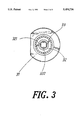
- FIG. 3 is a cross-sectional view showing the structure of an embodiment of the present invention.
- FIG. 4 is a vertical sectional view according to FIG. 3;
- FIG. 5 is a disassembled perspective view of an embodiment of the present invention.
- the present invention is a mini UHF coaxial cable connector which includes a die casting housing 31 having a first end and a second end, a dielectric 32 tightly fitted inside the die cast housing 31, a terminal 33 disposed inside the dielectric 32, a coaxial cable 41, and a ferrule 51 that surrounds and fixes a portion of the coaxial cable 41 connected to the second end of the die cast housing 31.
- the terminal 33 is formed at a first end with two axially extending and substantially circumferentially opposed elongated slots 331, a radially and inwardly projecting embossed area 332 formed near the inner end of the terminal 33, and two clamping feet 333 provided at an outer end of the terminal 33 opposite to the inner end thereof.
- the dielectric 32 is formed with two axially extended and substantially circumferentially opposite elongated ribs 321, radially and inwardly projecting from an inner wall of the dielectric 32 to just engage with the two long slots 331 of the terminal 33 when the terminal 33 is disposed inside the dielectric 32, such that the terminal 33 does not rotate relative to the dielectric 32.
- the coaxial cable 41 has an exposed center conductor 412 at a first end thereof, extending into the terminal 33 and being clamped therein by the two clamping feet 333.
- a part of a braid 410 of the coaxial cable 41 is used to wrap round the second end of the die cast housing 31, and then the ferrule 51 is used to cover and thereby tightly clamp the coaxial cable 41 at its outer insulation 413 to firmly connect the coaxial cable 41 to the second end of the die cast housing 31, as shown in FIG. 4.
- the die cast housing 31, the dielectric 32, the terminal 33, and the coaxial cable 41 of the connector according to the present invention are tightly connected to one another.
- the engagement of the elongated slots 331 of the terminal 33 with the elongated ribs 321 of the dielectric 32 prevents the terminal 33 from rotating relative to the dielectric 32 when the antenna is screwed into the connector and, as a result, breakage of the center conductor 412 of the coaxial cable 41 at the connecting and during screwing can be prevented.
- the embossed area 332 provided inside the terminal 33 may serve as a compressing means to provide better contact of the connecting end of the coaxial cable 41 with the terminal 33 and thereby permit a better electrical connection thereof.
- the mini UHF coaxial cable connector according to the present invention provides enhanced electrical connection and avoids twisting and breakage of the center conductor of the cable and, therefore, is practical and economical in use.
Abstract
Description
Claims (2)
Priority Applications (1)
| Application Number | Priority Date | Filing Date | Title |
|---|---|---|---|
| US08/247,689 US5454736A (en) | 1994-05-23 | 1994-05-23 | Mini UHF coaxial cable connector |
Applications Claiming Priority (1)
| Application Number | Priority Date | Filing Date | Title |
|---|---|---|---|
| US08/247,689 US5454736A (en) | 1994-05-23 | 1994-05-23 | Mini UHF coaxial cable connector |
Publications (1)
| Publication Number | Publication Date |
|---|---|
| US5454736A true US5454736A (en) | 1995-10-03 |
Family
ID=22935937
Family Applications (1)
| Application Number | Title | Priority Date | Filing Date |
|---|---|---|---|
| US08/247,689 Expired - Fee Related US5454736A (en) | 1994-05-23 | 1994-05-23 | Mini UHF coaxial cable connector |
Country Status (1)
| Country | Link |
|---|---|
| US (1) | US5454736A (en) |
Cited By (6)
| Publication number | Priority date | Publication date | Assignee | Title |
|---|---|---|---|---|
| EP0795938A1 (en) * | 1996-03-13 | 1997-09-17 | Osram Sylvania Inc. | Connector kit, connector assembly and method of making connector assembly |
| US5820408A (en) * | 1996-09-23 | 1998-10-13 | Wang; Tsan-Chi | Male coaxial cable connector |
| US6015315A (en) * | 1998-11-16 | 2000-01-18 | Itt Manufacturing Enterprises, Inc. | Impedance improved coax connector |
| US20110151696A1 (en) * | 2009-12-17 | 2011-06-23 | Cooper Technologies Company | Lockable Cable For Securing Fuse In A Loadbreak Elbow |
| US20120077376A1 (en) * | 2009-04-03 | 2012-03-29 | Kostal Kontakt Systeme Gmbh | Plug-In Connector for Connecting to a Coaxial Cable |
| CN109768445A (en) * | 2017-11-09 | 2019-05-17 | 定逸工业股份有限公司 | Concentric conductor electric connector |
Citations (5)
| Publication number | Priority date | Publication date | Assignee | Title |
|---|---|---|---|---|
| US3539976A (en) * | 1968-01-04 | 1970-11-10 | Amp Inc | Coaxial connector with controlled characteristic impedance |
| US3980385A (en) * | 1973-10-01 | 1976-09-14 | Shinagawa Automotive Electric Wire Co., Ltd. | Electrical connector |
| US4374604A (en) * | 1981-03-05 | 1983-02-22 | The Bendix Corporation | Contact for an electrical connector |
| US4859197A (en) * | 1987-07-07 | 1989-08-22 | Hosiden Electronics Co., Ltd. | Pin plug connector |
| US4995836A (en) * | 1988-12-01 | 1991-02-26 | Hosiden Electronics Co., Ltd. | Pin plug connector |
-
1994
- 1994-05-23 US US08/247,689 patent/US5454736A/en not_active Expired - Fee Related
Patent Citations (5)
| Publication number | Priority date | Publication date | Assignee | Title |
|---|---|---|---|---|
| US3539976A (en) * | 1968-01-04 | 1970-11-10 | Amp Inc | Coaxial connector with controlled characteristic impedance |
| US3980385A (en) * | 1973-10-01 | 1976-09-14 | Shinagawa Automotive Electric Wire Co., Ltd. | Electrical connector |
| US4374604A (en) * | 1981-03-05 | 1983-02-22 | The Bendix Corporation | Contact for an electrical connector |
| US4859197A (en) * | 1987-07-07 | 1989-08-22 | Hosiden Electronics Co., Ltd. | Pin plug connector |
| US4995836A (en) * | 1988-12-01 | 1991-02-26 | Hosiden Electronics Co., Ltd. | Pin plug connector |
Cited By (7)
| Publication number | Priority date | Publication date | Assignee | Title |
|---|---|---|---|---|
| EP0795938A1 (en) * | 1996-03-13 | 1997-09-17 | Osram Sylvania Inc. | Connector kit, connector assembly and method of making connector assembly |
| US5820408A (en) * | 1996-09-23 | 1998-10-13 | Wang; Tsan-Chi | Male coaxial cable connector |
| US6015315A (en) * | 1998-11-16 | 2000-01-18 | Itt Manufacturing Enterprises, Inc. | Impedance improved coax connector |
| US20120077376A1 (en) * | 2009-04-03 | 2012-03-29 | Kostal Kontakt Systeme Gmbh | Plug-In Connector for Connecting to a Coaxial Cable |
| US8323055B2 (en) * | 2009-04-03 | 2012-12-04 | Kostal Kontakt Systeme Gmbh | Plug-in connector for connecting to a coaxial cable |
| US20110151696A1 (en) * | 2009-12-17 | 2011-06-23 | Cooper Technologies Company | Lockable Cable For Securing Fuse In A Loadbreak Elbow |
| CN109768445A (en) * | 2017-11-09 | 2019-05-17 | 定逸工业股份有限公司 | Concentric conductor electric connector |
Similar Documents
| Publication | Publication Date | Title |
|---|---|---|
| US6669511B1 (en) | Structure for connecting shielded cable to shield connector | |
| CN101048918B (en) | Cable plug for a coaxial cable and method for mounting a cable plug of this type | |
| US6712645B1 (en) | Cable fixture of coaxial connector | |
| US4374458A (en) | Method of connecting a co-axial cable to a connector | |
| US3963321A (en) | Connector arrangement for coaxial cables | |
| US5766037A (en) | Connector for a radio frequency cable | |
| US6609937B2 (en) | Cable and phone plug assembly and method for producing it | |
| US5888098A (en) | Fuse holder device | |
| EP0351903A1 (en) | Dismountable coaxial coupling | |
| US5496968A (en) | Shielded cable connecting terminal | |
| JP2005158640A (en) | Multipole connector | |
| KR910013620A (en) | Circular DIN Electrical Connectors | |
| US6402550B2 (en) | Coaxial cable connector with main body tightly fastened to protective coating | |
| US5454736A (en) | Mini UHF coaxial cable connector | |
| JP2003223943A (en) | Coupling sleeve for inorganic insulation cable and connecting method | |
| US5846090A (en) | Rotational jack socket assembly | |
| KR880001072A (en) | Branch connector for coaxial cable | |
| US6142795A (en) | Electrical connector with grounded contact | |
| US5672079A (en) | Coaxial connector for manufacturing a coaxial high frequency cable | |
| JPH06251832A (en) | Tv coaxial plug | |
| JPH01167972A (en) | Tightening plug | |
| JPH05347162A (en) | Insulation electric terminal and its manufacture | |
| US6619988B2 (en) | Connector assembly | |
| JP3352529B2 (en) | Cable end structure for junction box and its outer plug | |
| JPH0342633Y2 (en) |
Legal Events
| Date | Code | Title | Description |
|---|---|---|---|
| AS | Assignment |
Owner name: ENTROPY INTERNATIONAL CO., LTD., TAIWAN Free format text: ASSIGNMENT OF ASSIGNORS INTEREST;ASSIGNOR:CHOU, LONG SHOU;REEL/FRAME:007014/0524 Effective date: 19940501 |
|
| FEPP | Fee payment procedure |
Free format text: PAYOR NUMBER ASSIGNED (ORIGINAL EVENT CODE: ASPN); ENTITY STATUS OF PATENT OWNER: SMALL ENTITY |
|
| FPAY | Fee payment |
Year of fee payment: 4 |
|
| FPAY | Fee payment |
Year of fee payment: 8 |
|
| REMI | Maintenance fee reminder mailed | ||
| LAPS | Lapse for failure to pay maintenance fees | ||
| STCH | Information on status: patent discontinuation |
Free format text: PATENT EXPIRED DUE TO NONPAYMENT OF MAINTENANCE FEES UNDER 37 CFR 1.362 |
|
| FP | Lapsed due to failure to pay maintenance fee |
Effective date: 20071003 |