US5440186A - Motor with isolated brush card assembly - Google Patents
Motor with isolated brush card assembly Download PDFInfo
- Publication number
- US5440186A US5440186A US08/121,025 US12102593A US5440186A US 5440186 A US5440186 A US 5440186A US 12102593 A US12102593 A US 12102593A US 5440186 A US5440186 A US 5440186A
- Authority
- US
- United States
- Prior art keywords
- armature
- motor
- brush card
- card assembly
- housing
- Prior art date
- Legal status (The legal status is an assumption and is not a legal conclusion. Google has not performed a legal analysis and makes no representation as to the accuracy of the status listed.)
- Expired - Lifetime
Links
Images


Classifications
-
- H—ELECTRICITY
- H02—GENERATION; CONVERSION OR DISTRIBUTION OF ELECTRIC POWER
- H02K—DYNAMO-ELECTRIC MACHINES
- H02K5/00—Casings; Enclosures; Supports
- H02K5/04—Casings or enclosures characterised by the shape, form or construction thereof
- H02K5/22—Auxiliary parts of casings not covered by groups H02K5/06-H02K5/20, e.g. shaped to form connection boxes or terminal boxes
- H02K5/225—Terminal boxes or connection arrangements
-
- H—ELECTRICITY
- H02—GENERATION; CONVERSION OR DISTRIBUTION OF ELECTRIC POWER
- H02K—DYNAMO-ELECTRIC MACHINES
- H02K5/00—Casings; Enclosures; Supports
- H02K5/04—Casings or enclosures characterised by the shape, form or construction thereof
- H02K5/14—Means for supporting or protecting brushes or brush holders
- H02K5/143—Means for supporting or protecting brushes or brush holders for cooperation with commutators
- H02K5/148—Slidably supported brushes
-
- H—ELECTRICITY
- H02—GENERATION; CONVERSION OR DISTRIBUTION OF ELECTRIC POWER
- H02K—DYNAMO-ELECTRIC MACHINES
- H02K5/00—Casings; Enclosures; Supports
- H02K5/04—Casings or enclosures characterised by the shape, form or construction thereof
- H02K5/10—Casings or enclosures characterised by the shape, form or construction thereof with arrangements for protection from ingress, e.g. water or fingers
-
- H—ELECTRICITY
- H02—GENERATION; CONVERSION OR DISTRIBUTION OF ELECTRIC POWER
- H02K—DYNAMO-ELECTRIC MACHINES
- H02K5/00—Casings; Enclosures; Supports
- H02K5/24—Casings; Enclosures; Supports specially adapted for suppression or reduction of noise or vibrations
-
- H—ELECTRICITY
- H02—GENERATION; CONVERSION OR DISTRIBUTION OF ELECTRIC POWER
- H02K—DYNAMO-ELECTRIC MACHINES
- H02K7/00—Arrangements for handling mechanical energy structurally associated with dynamo-electric machines, e.g. structural association with mechanical driving motors or auxiliary dynamo-electric machines
- H02K7/10—Structural association with clutches, brakes, gears, pulleys or mechanical starters
- H02K7/116—Structural association with clutches, brakes, gears, pulleys or mechanical starters with gears
- H02K7/1163—Structural association with clutches, brakes, gears, pulleys or mechanical starters with gears where at least two gears have non-parallel axes without having orbital motion
- H02K7/1166—Structural association with clutches, brakes, gears, pulleys or mechanical starters with gears where at least two gears have non-parallel axes without having orbital motion comprising worm and worm-wheel
Definitions
- This invention relates generally to motors and specifically to an electromagnetic motor with an isolated brush card assembly.
- dc direct current
- Typical operating applications include window lift motors, windshield wiper motors, anti-lock braking system motors, et cetera.
- the aforementioned motors often have brushes and commutators.
- the brush riggings for these motors vary in design but in general consist of boxes to house the brushes, a spring means to apply pressure to the brushes urging them against the commutator, and electrical leads to provide a current path to the brushes.
- a mounting surface secures these elements as well as provides a means to secure an entire brush card assembly to a housing in such a manner as to place the brushes in a proper working relationship with the commutator.
- the preferred embodiment of a new and useful motor has an isolated brush card assembly.
- the motor is comprised of a housing, a magnetic stator, an electromagnetic armature and a brush card assembly.
- the armature surrounds an armature shaft and a commutator is also mounted on the armature shaft longitudinally adjacent to the armature.
- the brush card assembly has an aperture with a pair of electrically conductive brushes positioned proximate thereto.
- the armature shaft is rotatably journalled within the aperture of the brush card assembly such that the pair of brushes electrically interface with an exterior surface of the commutator.
- provision is made for encapsulating a portion of the brush card assembly which interfaces with the housing in an elastomeric material.
- the brush card assembly has improved vibrational isolation from the adjacent housing.
- the elastomeric material reduces objectionable noise from being transmitted from the brush card assembly to the housing where it would otherwise be acoustically amplified.
- the partially encapsulated brush card assembly provides a water seal between a pair of housings. Accordingly, extraneous seals or gaskets are eliminated thereby improving the quality and lowering the assembly costs required to construct the present invention motor.
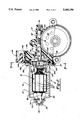
- FIG. 1 is an exploded perspective view of the preferred embodiment of the motor of the present invention
- FIG. 2 is a sectional view, taken along line 2--2 of FIG. 1, of the present invention motor
- FIG. 3 is an end elevational view, taken along line 3--3 of FIG. 2, of a brush card assembly of the present invention motor;
- FIG. 4 is an end elevational view, opposite from that of FIG. 3, showing the brush card assembly of the present invention motor of FIG. 1 with an elastomeric material removed;
- FIG. 5 is an end elevational view, similar to that of FIG. 4, showing the brush card assembly of the present invention motor of FIG. 1 partially encapsulated within the elastomeric material;
- FIG. 6 is a fragmentary perspective view, taken along line 6--6 of FIG. 5, showing the brush card assembly of the present invention motor.
- a motor 10 is shown having an armature housing 12, a gear housing 14, a stator 16, a rotor or armature 18, a brush card assembly 20 and a gear 22.
- Armature housing 12 has a substantially cylindrical bore 30 extending therein defined by an inside surface, against which stator 16 is internally mounted.
- Stator 16 is permanently magnetic in nature.
- Gear housing 14 also has a bore 32 extending longitudinally therewithin defined by an inside surface and further has a transverse passageway 34 therethrough which intersects a gear cavity 36.
- Armature housing 12 and gear housing 14 both have a flange, respectively 37 and 38, projecting therearound proximate with an open end 40 and 42 of each housing 12 and 14, respectively.
- Armature housing 12 is preferably made from a stamped metallic material and gear housing 14 is preferably injection molded from a 45% glass filled Zytel which can be purchased from DuPont.
- Armature 18 is centrally mounted around an armature shaft 50.
- Armature shaft 50 has a pedestal segment 52 and a driving segment 54 protruding longitudinally from each end of armature 18.
- armature 18 is an electromagnetic device constructed from a plurality of wire windings 56 wrapped inside a plurality of armature pack slots which are juxtaposed between a plurality of magnetically conductive armature teeth 58.
- a commutator 60 is positioned longitudinally adjacent to armature 18 and surrounds armature shaft 50 near driving segment 54.
- Armature shaft 50 is rotatably journalled within armature and gear housings 12 and 14, respectively, by a pair of bearings 70 and retainers 72.
- armature shaft 50 contains helical threads 76 which operably engage gear 22 thereby providing a drive means for operating a window lift mechanism or the like.
- Brush card assembly 20 has a support member 90, an interface portion 92 and an electrical connector 94. This can best be seen in FIGS. 2 through 5.
- Support member 90 is injection molded from a non-conductive polymeric material such as Rynite SST-35 which can be obtained from DuPont.
- support member 90 has a substantially flat pair of faces 96 and 98 with a pair of brush boxes 100 projecting from face 96.
- Each brush box 100 has an internal cavity which holds and positions a solid rectangular metallic brush 102. Brushes 102 are held within brush boxes 100 for reciprocating motion adjacent to a circular aperture 103, defined by an inner edge, within support member 90.
- a pair of brush springs 104 are positioned to urge brushes 102 inwardly against commutator 60.
- a pair of conductive metallic traces 106 and 108 are insert molded within brush card assembly 20. Traces 106 and 108 terminate within electrical connector 94 thereby forming electrical contacts 110 and 112. This provides for an external dc electrical connection with an automotive vehicle wire harness (not shown). Electrically conductive shunts 120 transmit electrical current from traces 106 and 108 either directly to brushes 102 or indirectly through a circuit breaker 122. Accordingly, electrical current is supplied through electrical contacts 110 and 112, through traces 106 and 108, through shunts 120 and circuit breaker 122, through brushes 102, through commutator 60 and to wire windings 56 so as to allow armature 18 to create an electromagnetic field therearound thereby acting in association with stator 16 to rotate armature shaft 50.
- This present invention specifically pertains to a means for vibrationally isolating brush card assembly 20 from armature and gear housings, respectively 12 and 14, thus reducing audible noise.
- This is accomplished by partially encapsulating an inner lip member 140 which surrounds an upturned peripheral wall 142 bordering support segment 90 of brush card assembly 20.
- This inner lip member 140 is shown unencapsulated in FIG. 4.
- inner lip member 140 is illustrated as being encapsulated within an elastomeric material 144 such as Alcryn 2060 which can be purchased from DuPont.
- a channel portion 146 is also partially encapsulated. This channel portion 146 serves to support electrical connector 94 upon an upstanding rib 148 formed within flange 38 of gear housing 14.
- elastomeric material 144 is supplementally retained upon inner lip member 140 and peripheral wall 142 through a series of dovetail interlocking formations 150. Therefore, brush card assembly 20 is vibrationally isolated from housings 12 and 14 when affixed between flanges 37 and 38. Additionally, elastomeric material 144 provides a water tight seal between armature housing 12 and gear housing 14 when brush card assembly 20 is compressibly trapped therebetween.
Abstract
Description
Claims (16)
Priority Applications (6)
| Application Number | Priority Date | Filing Date | Title |
|---|---|---|---|
| US08/121,025 US5440186A (en) | 1993-09-13 | 1993-09-13 | Motor with isolated brush card assembly |
| CA002147514A CA2147514A1 (en) | 1993-09-13 | 1994-09-09 | Motor with isolated brush card assembly |
| DE69404822T DE69404822T2 (en) | 1993-09-13 | 1994-09-09 | MOTOR WITH INSULATED BRUSH ARRANGEMENT |
| EP94929166A EP0669052B1 (en) | 1993-09-13 | 1994-09-09 | Motor with isolated brush card assembly |
| ES94929166T ES2106564T3 (en) | 1993-09-13 | 1994-09-09 | ENGINE WITH SEPARATE STATOR CARD. |
| PCT/US1994/010184 WO1995008209A1 (en) | 1993-09-13 | 1994-09-09 | Motor with isolated brush card assembly |
Applications Claiming Priority (1)
| Application Number | Priority Date | Filing Date | Title |
|---|---|---|---|
| US08/121,025 US5440186A (en) | 1993-09-13 | 1993-09-13 | Motor with isolated brush card assembly |
Publications (1)
| Publication Number | Publication Date |
|---|---|
| US5440186A true US5440186A (en) | 1995-08-08 |
Family
ID=22394019
Family Applications (1)
| Application Number | Title | Priority Date | Filing Date |
|---|---|---|---|
| US08/121,025 Expired - Lifetime US5440186A (en) | 1993-09-13 | 1993-09-13 | Motor with isolated brush card assembly |
Country Status (6)
| Country | Link |
|---|---|
| US (1) | US5440186A (en) |
| EP (1) | EP0669052B1 (en) |
| CA (1) | CA2147514A1 (en) |
| DE (1) | DE69404822T2 (en) |
| ES (1) | ES2106564T3 (en) |
| WO (1) | WO1995008209A1 (en) |
Cited By (45)
| Publication number | Priority date | Publication date | Assignee | Title |
|---|---|---|---|---|
| US5539264A (en) * | 1992-01-31 | 1996-07-23 | Mitsubishi Denki Kabushiki Kaisha | Brush holder assembly |
| US5576586A (en) * | 1992-10-24 | 1996-11-19 | Licentia Patent-Verwaltungs-Gmbh | Electric motor, particularly a commutator motor sealed to be liquid-tight, for driving an axially flange-mounted hydraulic pump |
| US5650676A (en) * | 1992-10-24 | 1997-07-22 | Licentia Patent-Verwaltungs-Gmbh | Electric motor with improved seal |
| US5653144A (en) | 1993-02-09 | 1997-08-05 | Fenelon; Paul J. | Stress dissipation apparatus |
| US5796198A (en) * | 1994-09-27 | 1998-08-18 | Honda Giken Kogyo Kabushiki Kaisha | Electric motor for a power steering apparatus |
| US5886448A (en) * | 1996-08-05 | 1999-03-23 | Mitsuba Corporation | Feeder structure in electric motor |
| US5903114A (en) * | 1995-04-28 | 1999-05-11 | Ut Automotive Dearborn, Inc. | Multi-functional apparatus employing an intermittent motion mechanism |
| US5907885A (en) * | 1997-10-09 | 1999-06-01 | Ut Automotive Dearborn, Inc. | Multi-functional apparatus for use in an automotive vehicle employing multiple tracks |
| FR2772205A1 (en) * | 1997-11-28 | 1999-06-11 | Buhler Motor Gmbh | HOUSING FOR A SERVOMOTOR, PARTICULARLY FOR USE IN THE AUTOMOTIVE FIELD |
| US5943913A (en) | 1993-02-09 | 1999-08-31 | Fenelon; Paul J. | Rotatable apparatus having a stress dissipation structure |
| US5956998A (en) | 1996-06-06 | 1999-09-28 | Fenelon; Paul J. | Stress reduction gear and apparatus using same |
| US6002323A (en) * | 1997-10-09 | 1999-12-14 | Lear Automotive Dearborn, Inc. | Audible feedback apparatus for indicating operation and position of a movable element |
| US6205612B1 (en) | 1997-10-09 | 2001-03-27 | Ut Automotive Dearborn, Inc. | Window wiper system for an automotive vehicle |
| DE19963160A1 (en) * | 1999-12-24 | 2001-06-28 | Valeo Auto Electric Gmbh | Drive motor for vehicle windscreen wiper, has brush holder plate to secure carbon brushes, which is clamped between gear and motor casings |
| US6259184B1 (en) * | 1996-10-24 | 2001-07-10 | Mannesmann Vdo Ag | Load shifting device |
| FR2812471A1 (en) * | 2000-07-31 | 2002-02-01 | Vameo Electrical Systems Inc | Motor/reduction gearing assembly has gearbox and motorbox which contain endless screw, motor and motor brush carrier which has joint fixed to it which is compressed between motor and gearbox |
| US6455963B2 (en) * | 1999-12-20 | 2002-09-24 | Aisin Seiki Kabushiki Kaisha | Electric motor |
| US20020163280A1 (en) * | 2001-04-19 | 2002-11-07 | Fumio Nakajima | Motor and brush device |
| US20030062800A1 (en) * | 2000-10-12 | 2003-04-03 | Kenji Nagai | Starter motor for internal combustion engines |
| US6555943B2 (en) * | 1999-12-24 | 2003-04-29 | Valeo Auto-Electric Wischer Und Motoren Gmbh | Geared motor with a connector for a brush mounting plate having a ground brush |
| US20030080635A1 (en) * | 2001-10-30 | 2003-05-01 | Robert Bosch Corporation | Isolation system for a motor |
| EP1361643A2 (en) | 2002-05-10 | 2003-11-12 | Showa Corporation | Electric motor apparatus |
| US20040164634A1 (en) * | 2003-02-10 | 2004-08-26 | Siemens Vdo Automotive Inc. | Ambidextrous electronic window lift motor |
| DE10342219A1 (en) * | 2003-09-11 | 2005-04-21 | K Tec Kunststoffverarbeitung G | Pot/beaker-shaped carrier for carbon brushes, electrical wiring, possibly electrical, electronic components has separately manufactured frame, carrier, frame connected to carrier in shape- and/or force-locking and/or material-engaged manner |
| US20050106928A1 (en) * | 2003-11-15 | 2005-05-19 | Pierburg Gmbh | Contact unit |
| US20050134139A1 (en) * | 2003-09-11 | 2005-06-23 | K-Tec Gmbh | Pot or cup-shaped carrier |
| US20050264127A1 (en) * | 2003-10-29 | 2005-12-01 | Siemens Aktiengesellschaft | Brush holder for an electric-motor driven actuator and an electric-motor driven actuator |
| US20050285463A1 (en) * | 2004-06-29 | 2005-12-29 | Hockaday Shepard L | Brush assemblies |
| US20060191736A1 (en) * | 2003-06-25 | 2006-08-31 | Atsushi Maeda | Electric power steering device |
| WO2006096845A2 (en) * | 2005-03-08 | 2006-09-14 | Manning John B | Electric motor starting device |
| EP1710893A1 (en) * | 2005-04-06 | 2006-10-11 | Siemens Aktiengesellschaft | Brush-system for an electrical actuator |
| US7466056B2 (en) | 2006-10-06 | 2008-12-16 | Remi International, Inc | Dynamoelectric machine brush holder assembly and method |
| US20090224618A1 (en) * | 2008-03-07 | 2009-09-10 | Robert Bosch Llc | Bearing for an electric actuator motor |
| US7696666B2 (en) | 2006-10-06 | 2010-04-13 | Remy Technologies, L.L.C. | Dynamoelectric machine grommet |
| US7705512B2 (en) | 2006-10-06 | 2010-04-27 | Remy International, Inc. | Dynamoelectric machine conductor |
| US8088086B1 (en) | 2006-06-22 | 2012-01-03 | Schmuck Allison J | Automated pet scratching device and associated method |
| US20120183348A1 (en) * | 2010-12-22 | 2012-07-19 | Multivac Sepp Haggenmueller Gmbh & Co. Kg | Drive unit with gasket |
| ITPD20110229A1 (en) * | 2011-07-06 | 2013-01-07 | Nuova Sme S P A | PERFECT STRUCTURE OF ELECTRIC DIRECT CURRENT GEARED MOTOR, PARTICULARLY FOR GLASSWORKS, SEATS, WIPERS AND OTHER APPLICATIONS IN VEHICLES |
| US20140312731A1 (en) * | 2013-04-22 | 2014-10-23 | Asmo Co., Ltd. | Motor |
| CN104467279A (en) * | 2013-09-18 | 2015-03-25 | 阿斯莫株式会社 | Motor and method for manufacturing motor |
| WO2014124802A3 (en) * | 2013-02-15 | 2015-03-26 | Robert Bosch Gmbh | Transmission-drive unit and use thereof |
| WO2016042577A3 (en) * | 2014-09-19 | 2016-06-09 | Agile Electric Sub Assembly Pvt Limited | Dc motor assembly |
| JP2017225240A (en) * | 2016-06-15 | 2017-12-21 | アスモ株式会社 | Brush holder and manufacturing method of the same |
| CN109155569A (en) * | 2016-06-29 | 2019-01-04 | 株式会社美姿把 | Motor with deceleration mechanism |
| US10329826B2 (en) * | 2015-09-30 | 2019-06-25 | Johnson Electric International AG | Driving mechanism |
Families Citing this family (5)
| Publication number | Priority date | Publication date | Assignee | Title |
|---|---|---|---|---|
| DE4440479C2 (en) * | 1994-11-12 | 1997-08-21 | Temic Auto Electr Motors Gmbh | Electric motor drive for an aggregate that can be flanged to the front of a motor housing |
| FR2748613B1 (en) * | 1996-05-13 | 1998-07-31 | Rockwell Lvs | COLLECTOR HOUSING AND CONNECTOR ASSEMBLY |
| DE10162247C1 (en) | 2001-01-18 | 2002-12-19 | Siemens Ag | Motor-pump unit, in particular motor vehicle braking device |
| US6945757B2 (en) | 2001-01-18 | 2005-09-20 | Siemens Aktiengesellschaft | Motor pump unit, particularly a motor vehicle braking device |
| DE102018212041A1 (en) * | 2018-07-19 | 2020-01-23 | Robert Bosch Gmbh | Wiper drive and method for mounting the wiper drive |
Citations (16)
| Publication number | Priority date | Publication date | Assignee | Title |
|---|---|---|---|---|
| US2207251A (en) * | 1938-07-30 | 1940-07-09 | Rca Corp | Electric motor |
| US3482125A (en) * | 1963-04-29 | 1969-12-02 | Licentia Gmbh | Adhesive soaked absorbent layer for centering and joining components together |
| US3654504A (en) * | 1971-03-29 | 1972-04-04 | Gen Electric | Brush mechanism |
| US3749457A (en) * | 1970-12-19 | 1973-07-31 | Siemens Ag | Guide bearing for use in the housing or bearing plate of a machine or other apparatus |
| US4293789A (en) * | 1979-09-10 | 1981-10-06 | General Motors Corporation | Dynamoelectric machine brush rigging |
| US4623812A (en) * | 1984-03-12 | 1986-11-18 | U.S. Philips Corporation | Electric motor with thin rotor-damping layer |
| US4694214A (en) * | 1986-03-07 | 1987-09-15 | United Technologies Electro Systems, Inc. | Brush holder for dynamoelectric machines |
| US4713568A (en) * | 1985-09-26 | 1987-12-15 | Siemens Aktiengesellschaft | Closed motor/transmission unit |
| US4792307A (en) * | 1986-11-14 | 1988-12-20 | United Technologies Electro Systems, Inc. | Electrical contact and terminal assembly |
| US4910861A (en) * | 1988-10-07 | 1990-03-27 | Emerson Electric Co. | Method of manufacturing retention structure for electric motor rotor magnets |
| US4952831A (en) * | 1988-07-07 | 1990-08-28 | Mitsubishi Denki Kabushiki Kaisha | Device for waterproofing around terminal bolt |
| US4978876A (en) * | 1988-03-31 | 1990-12-18 | Schunk Motorensysteme Gmbh | Cup-shaped support for an electromotor |
| US5006747A (en) * | 1990-04-02 | 1991-04-09 | United Technologies Motor Systems, Inc. | Dynamoelectric machine brush rigging and method of assembly |
| US5159221A (en) * | 1989-08-31 | 1992-10-27 | Mitsuba Electric Manufacturing Co., Ltd. | Brush holder structure in electric motor |
| US5237231A (en) * | 1989-10-19 | 1993-08-17 | General Electric Company | Structured product dynamoelectric machine |
| US5280210A (en) * | 1987-12-30 | 1994-01-18 | Kress-Elektric Gmbh & Co. Elektromotorenfabrik | Universal electric motor with a switch ring mounted adjacent the brushes |
Family Cites Families (7)
| Publication number | Priority date | Publication date | Assignee | Title |
|---|---|---|---|---|
| IT1038004B (en) * | 1974-05-16 | 1979-11-20 | Siemens Ag | COLLECTOR ELECTRIC MOTOR |
| US4845396A (en) * | 1986-08-19 | 1989-07-04 | Capsonic Group, Inc. | Motor brush holder assembly |
| JPS63270111A (en) * | 1987-04-30 | 1988-11-08 | Toshiba Corp | Plastic composite member and its manufacture |
| WO1991003095A1 (en) * | 1989-08-25 | 1991-03-07 | Siemens Aktiengesellschaft | Electric motor with watertight construction |
| JPH0649100Y2 (en) * | 1989-12-04 | 1994-12-12 | 株式会社三ツ葉電機製作所 | DC machine wiring device |
| US5152588A (en) * | 1991-06-28 | 1992-10-06 | General Motors Corporation | Anti-lock braking system |
| DE4243716A1 (en) * | 1992-12-23 | 1994-06-30 | Bosch Gmbh Robert | Bearing end plate for small DC commutator motors |
-
1993
- 1993-09-13 US US08/121,025 patent/US5440186A/en not_active Expired - Lifetime
-
1994
- 1994-09-09 ES ES94929166T patent/ES2106564T3/en not_active Expired - Lifetime
- 1994-09-09 EP EP94929166A patent/EP0669052B1/en not_active Expired - Lifetime
- 1994-09-09 WO PCT/US1994/010184 patent/WO1995008209A1/en active IP Right Grant
- 1994-09-09 DE DE69404822T patent/DE69404822T2/en not_active Expired - Lifetime
- 1994-09-09 CA CA002147514A patent/CA2147514A1/en not_active Abandoned
Patent Citations (16)
| Publication number | Priority date | Publication date | Assignee | Title |
|---|---|---|---|---|
| US2207251A (en) * | 1938-07-30 | 1940-07-09 | Rca Corp | Electric motor |
| US3482125A (en) * | 1963-04-29 | 1969-12-02 | Licentia Gmbh | Adhesive soaked absorbent layer for centering and joining components together |
| US3749457A (en) * | 1970-12-19 | 1973-07-31 | Siemens Ag | Guide bearing for use in the housing or bearing plate of a machine or other apparatus |
| US3654504A (en) * | 1971-03-29 | 1972-04-04 | Gen Electric | Brush mechanism |
| US4293789A (en) * | 1979-09-10 | 1981-10-06 | General Motors Corporation | Dynamoelectric machine brush rigging |
| US4623812A (en) * | 1984-03-12 | 1986-11-18 | U.S. Philips Corporation | Electric motor with thin rotor-damping layer |
| US4713568A (en) * | 1985-09-26 | 1987-12-15 | Siemens Aktiengesellschaft | Closed motor/transmission unit |
| US4694214A (en) * | 1986-03-07 | 1987-09-15 | United Technologies Electro Systems, Inc. | Brush holder for dynamoelectric machines |
| US4792307A (en) * | 1986-11-14 | 1988-12-20 | United Technologies Electro Systems, Inc. | Electrical contact and terminal assembly |
| US5280210A (en) * | 1987-12-30 | 1994-01-18 | Kress-Elektric Gmbh & Co. Elektromotorenfabrik | Universal electric motor with a switch ring mounted adjacent the brushes |
| US4978876A (en) * | 1988-03-31 | 1990-12-18 | Schunk Motorensysteme Gmbh | Cup-shaped support for an electromotor |
| US4952831A (en) * | 1988-07-07 | 1990-08-28 | Mitsubishi Denki Kabushiki Kaisha | Device for waterproofing around terminal bolt |
| US4910861A (en) * | 1988-10-07 | 1990-03-27 | Emerson Electric Co. | Method of manufacturing retention structure for electric motor rotor magnets |
| US5159221A (en) * | 1989-08-31 | 1992-10-27 | Mitsuba Electric Manufacturing Co., Ltd. | Brush holder structure in electric motor |
| US5237231A (en) * | 1989-10-19 | 1993-08-17 | General Electric Company | Structured product dynamoelectric machine |
| US5006747A (en) * | 1990-04-02 | 1991-04-09 | United Technologies Motor Systems, Inc. | Dynamoelectric machine brush rigging and method of assembly |
Cited By (66)
| Publication number | Priority date | Publication date | Assignee | Title |
|---|---|---|---|---|
| US5539264A (en) * | 1992-01-31 | 1996-07-23 | Mitsubishi Denki Kabushiki Kaisha | Brush holder assembly |
| US5576586A (en) * | 1992-10-24 | 1996-11-19 | Licentia Patent-Verwaltungs-Gmbh | Electric motor, particularly a commutator motor sealed to be liquid-tight, for driving an axially flange-mounted hydraulic pump |
| US5650676A (en) * | 1992-10-24 | 1997-07-22 | Licentia Patent-Verwaltungs-Gmbh | Electric motor with improved seal |
| US5943913A (en) | 1993-02-09 | 1999-08-31 | Fenelon; Paul J. | Rotatable apparatus having a stress dissipation structure |
| US5653144A (en) | 1993-02-09 | 1997-08-05 | Fenelon; Paul J. | Stress dissipation apparatus |
| US5796198A (en) * | 1994-09-27 | 1998-08-18 | Honda Giken Kogyo Kabushiki Kaisha | Electric motor for a power steering apparatus |
| US5903114A (en) * | 1995-04-28 | 1999-05-11 | Ut Automotive Dearborn, Inc. | Multi-functional apparatus employing an intermittent motion mechanism |
| US5956998A (en) | 1996-06-06 | 1999-09-28 | Fenelon; Paul J. | Stress reduction gear and apparatus using same |
| US5886448A (en) * | 1996-08-05 | 1999-03-23 | Mitsuba Corporation | Feeder structure in electric motor |
| US6259184B1 (en) * | 1996-10-24 | 2001-07-10 | Mannesmann Vdo Ag | Load shifting device |
| US5907885A (en) * | 1997-10-09 | 1999-06-01 | Ut Automotive Dearborn, Inc. | Multi-functional apparatus for use in an automotive vehicle employing multiple tracks |
| US6002323A (en) * | 1997-10-09 | 1999-12-14 | Lear Automotive Dearborn, Inc. | Audible feedback apparatus for indicating operation and position of a movable element |
| US6205612B1 (en) | 1997-10-09 | 2001-03-27 | Ut Automotive Dearborn, Inc. | Window wiper system for an automotive vehicle |
| FR2772205A1 (en) * | 1997-11-28 | 1999-06-11 | Buhler Motor Gmbh | HOUSING FOR A SERVOMOTOR, PARTICULARLY FOR USE IN THE AUTOMOTIVE FIELD |
| US6455963B2 (en) * | 1999-12-20 | 2002-09-24 | Aisin Seiki Kabushiki Kaisha | Electric motor |
| DE19963160A1 (en) * | 1999-12-24 | 2001-06-28 | Valeo Auto Electric Gmbh | Drive motor for vehicle windscreen wiper, has brush holder plate to secure carbon brushes, which is clamped between gear and motor casings |
| US6555943B2 (en) * | 1999-12-24 | 2003-04-29 | Valeo Auto-Electric Wischer Und Motoren Gmbh | Geared motor with a connector for a brush mounting plate having a ground brush |
| US6459188B1 (en) * | 2000-07-31 | 2002-10-01 | Valeo Electrical Systems, Inc. | Integral brush holder gasket |
| FR2812471A1 (en) * | 2000-07-31 | 2002-02-01 | Vameo Electrical Systems Inc | Motor/reduction gearing assembly has gearbox and motorbox which contain endless screw, motor and motor brush carrier which has joint fixed to it which is compressed between motor and gearbox |
| US20030062800A1 (en) * | 2000-10-12 | 2003-04-03 | Kenji Nagai | Starter motor for internal combustion engines |
| KR100885657B1 (en) * | 2001-04-19 | 2009-02-25 | 가부시키가이샤 미츠바 | Motor and brush device |
| US20020163280A1 (en) * | 2001-04-19 | 2002-11-07 | Fumio Nakajima | Motor and brush device |
| US20050121995A1 (en) * | 2001-04-19 | 2005-06-09 | Fumio Nakajima | Motor and brush device |
| US7154203B2 (en) | 2001-04-19 | 2006-12-26 | Jidosha Denki Kogyo Kabushiki Kaisha | Motor and brush device |
| US20030080635A1 (en) * | 2001-10-30 | 2003-05-01 | Robert Bosch Corporation | Isolation system for a motor |
| US6717299B2 (en) * | 2001-10-30 | 2004-04-06 | Robert Bosch Corporation | Isolation system for a motor |
| US20030209382A1 (en) * | 2002-05-10 | 2003-11-13 | Yohei Hama | Electric motor apparatus |
| US6745865B2 (en) * | 2002-05-10 | 2004-06-08 | Showa Corporation | Electric motor apparatus |
| EP1361643A3 (en) * | 2002-05-10 | 2004-02-04 | Showa Corporation | Electric motor apparatus |
| EP1361643A2 (en) | 2002-05-10 | 2003-11-12 | Showa Corporation | Electric motor apparatus |
| US20040164634A1 (en) * | 2003-02-10 | 2004-08-26 | Siemens Vdo Automotive Inc. | Ambidextrous electronic window lift motor |
| US7098562B2 (en) | 2003-02-10 | 2006-08-29 | Siemens Vdo Automotive Corporation | Ambidextrous electronic window lift motor |
| US20060191736A1 (en) * | 2003-06-25 | 2006-08-31 | Atsushi Maeda | Electric power steering device |
| US20050134128A1 (en) * | 2003-09-11 | 2005-06-23 | K-Tec Gmbh | Pot-like or cup-like carrier |
| US7176591B2 (en) | 2003-09-11 | 2007-02-13 | K-Tec Kunststoffverarbeitung Gmbh | Pot-like or cup-like carrier |
| DE10342219A1 (en) * | 2003-09-11 | 2005-04-21 | K Tec Kunststoffverarbeitung G | Pot/beaker-shaped carrier for carbon brushes, electrical wiring, possibly electrical, electronic components has separately manufactured frame, carrier, frame connected to carrier in shape- and/or force-locking and/or material-engaged manner |
| US7045928B2 (en) * | 2003-09-11 | 2006-05-16 | K-Tec Kunststoffverarbeitung Gmbh | Pot or cup-shaped carrier |
| US20050134139A1 (en) * | 2003-09-11 | 2005-06-23 | K-Tec Gmbh | Pot or cup-shaped carrier |
| US20050264127A1 (en) * | 2003-10-29 | 2005-12-01 | Siemens Aktiengesellschaft | Brush holder for an electric-motor driven actuator and an electric-motor driven actuator |
| US7230362B2 (en) * | 2003-10-29 | 2007-06-12 | Siemens Ag | Brush holder for an electric-motor driven actuator and an electric-motor driven actuator |
| US6958918B2 (en) * | 2003-11-15 | 2005-10-25 | Pierburg Gmbh | Contact unit |
| US20050106928A1 (en) * | 2003-11-15 | 2005-05-19 | Pierburg Gmbh | Contact unit |
| US20050285463A1 (en) * | 2004-06-29 | 2005-12-29 | Hockaday Shepard L | Brush assemblies |
| WO2006096845A2 (en) * | 2005-03-08 | 2006-09-14 | Manning John B | Electric motor starting device |
| WO2006096845A3 (en) * | 2005-03-08 | 2008-12-11 | John B Manning | Electric motor starting device |
| WO2006106064A1 (en) * | 2005-04-06 | 2006-10-12 | Siemens Vdo Automotive Ag | Brush system for an electric actuator |
| EP1710893A1 (en) * | 2005-04-06 | 2006-10-11 | Siemens Aktiengesellschaft | Brush-system for an electrical actuator |
| US20090121578A1 (en) * | 2005-04-06 | 2009-05-14 | Matthias Benkert | Brush system for an electric actuator |
| US8088086B1 (en) | 2006-06-22 | 2012-01-03 | Schmuck Allison J | Automated pet scratching device and associated method |
| US7696666B2 (en) | 2006-10-06 | 2010-04-13 | Remy Technologies, L.L.C. | Dynamoelectric machine grommet |
| US7705512B2 (en) | 2006-10-06 | 2010-04-27 | Remy International, Inc. | Dynamoelectric machine conductor |
| US7466056B2 (en) | 2006-10-06 | 2008-12-16 | Remi International, Inc | Dynamoelectric machine brush holder assembly and method |
| US20090224618A1 (en) * | 2008-03-07 | 2009-09-10 | Robert Bosch Llc | Bearing for an electric actuator motor |
| US8084905B2 (en) | 2008-03-07 | 2011-12-27 | Robert Bosch Gmbh | Bearing for an electric actuator motor |
| US20120183348A1 (en) * | 2010-12-22 | 2012-07-19 | Multivac Sepp Haggenmueller Gmbh & Co. Kg | Drive unit with gasket |
| ITPD20110229A1 (en) * | 2011-07-06 | 2013-01-07 | Nuova Sme S P A | PERFECT STRUCTURE OF ELECTRIC DIRECT CURRENT GEARED MOTOR, PARTICULARLY FOR GLASSWORKS, SEATS, WIPERS AND OTHER APPLICATIONS IN VEHICLES |
| WO2014124802A3 (en) * | 2013-02-15 | 2015-03-26 | Robert Bosch Gmbh | Transmission-drive unit and use thereof |
| US20140312731A1 (en) * | 2013-04-22 | 2014-10-23 | Asmo Co., Ltd. | Motor |
| US9252646B2 (en) * | 2013-04-22 | 2016-02-02 | Asmo Co., Ltd. | Motor with diffusion stopper |
| CN104467279A (en) * | 2013-09-18 | 2015-03-25 | 阿斯莫株式会社 | Motor and method for manufacturing motor |
| JP2015061383A (en) * | 2013-09-18 | 2015-03-30 | アスモ株式会社 | Motor |
| CN104467279B (en) * | 2013-09-18 | 2018-05-04 | 阿斯莫株式会社 | The manufacture method of motor and motor |
| WO2016042577A3 (en) * | 2014-09-19 | 2016-06-09 | Agile Electric Sub Assembly Pvt Limited | Dc motor assembly |
| US10329826B2 (en) * | 2015-09-30 | 2019-06-25 | Johnson Electric International AG | Driving mechanism |
| JP2017225240A (en) * | 2016-06-15 | 2017-12-21 | アスモ株式会社 | Brush holder and manufacturing method of the same |
| CN109155569A (en) * | 2016-06-29 | 2019-01-04 | 株式会社美姿把 | Motor with deceleration mechanism |
Also Published As
| Publication number | Publication date |
|---|---|
| EP0669052A1 (en) | 1995-08-30 |
| CA2147514A1 (en) | 1995-03-23 |
| EP0669052B1 (en) | 1997-08-06 |
| DE69404822T2 (en) | 1998-01-29 |
| DE69404822D1 (en) | 1997-09-11 |
| WO1995008209A1 (en) | 1995-03-23 |
| ES2106564T3 (en) | 1997-11-01 |
Similar Documents
| Publication | Publication Date | Title |
|---|---|---|
| US5440186A (en) | Motor with isolated brush card assembly | |
| EP0538495B1 (en) | Motor window raising drive for a vehicle | |
| KR100673575B1 (en) | Motor having control circuit board for controlling its rotation | |
| JP2608710B2 (en) | Wiring device in commutator motor for power tool | |
| KR101329589B1 (en) | Brush holder and method for manufacturing brush holder | |
| US7531938B2 (en) | Insertable brush holder assembly for electric motor | |
| US6011341A (en) | DC motor having a brush holder provided with a terminal projection portion | |
| US5086243A (en) | Rotation detector for a commutator motor excited by pole units | |
| JP3855762B2 (en) | AC generator for vehicles | |
| JP2010525770A (en) | DC motor with bushing capacitor | |
| US4677333A (en) | Brush holder mountable in recess of peripheral wall of electric machine | |
| US5041751A (en) | Mounting section structure for mounting a circuit breaker in a brush holder stay | |
| CA2444796A1 (en) | Method and apparatus for mounting electronic motor controls | |
| DE4440479C2 (en) | Electric motor drive for an aggregate that can be flanged to the front of a motor housing | |
| KR101655112B1 (en) | Brushless DC Motor | |
| JP2804108B2 (en) | Motor noise prevention structure | |
| JP2863996B2 (en) | Brush wiring structure in DC motor | |
| JP2003079109A (en) | Brush holder and electric motor | |
| GB2536721A (en) | Integrated door lock sub-assembly | |
| JP4800980B2 (en) | motor | |
| JPH07322552A (en) | Miniature motor | |
| JP7055293B2 (en) | Waterproof connector | |
| GB2173648A (en) | Electric motors and their assembly | |
| JP6536249B2 (en) | Electric rotating machine | |
| JP2810003B2 (en) | Small electric motor |
Legal Events
| Date | Code | Title | Description |
|---|---|---|---|
| AS | Assignment |
Owner name: UNITED TECHNOLOGIES AUTOMOTIVE, INC., MICHIGAN Free format text: ASSIGNMENT OF ASSIGNORS INTEREST;ASSIGNORS:FORSELL, ERIC A.;MACKAY, JEFFREY L.;REEL/FRAME:006694/0726 Effective date: 19930913 |
|
| AS | Assignment |
Owner name: UNITED TECHNOLOGIES MOTOR SYSTEMS, INC., MISSISSIP Free format text: ASSIGNMENT OF ASSIGNORS INTEREST;ASSIGNOR:UNITED TECHNOLOGIES AUTOMOTIVE, INC.;REEL/FRAME:006834/0118 Effective date: 19940105 |
|
| STCF | Information on status: patent grant |
Free format text: PATENTED CASE |
|
| CC | Certificate of correction | ||
| FEPP | Fee payment procedure |
Free format text: PAYOR NUMBER ASSIGNED (ORIGINAL EVENT CODE: ASPN); ENTITY STATUS OF PATENT OWNER: LARGE ENTITY |
|
| FPAY | Fee payment |
Year of fee payment: 4 |
|
| AS | Assignment |
Owner name: MOTORS ACQUISITION CORP., MICHIGAN Free format text: ASSIGNMENT OF ASSIGNORS INTEREST;ASSIGNOR:UNITED TECHNOLOGIES MOTOR SYSTEMS INC.;REEL/FRAME:010327/0600 Effective date: 19990622 |
|
| AS | Assignment |
Owner name: JOHNSON ELECTRIC AUTOMOTIVE, INC., MICHIGAN Free format text: ASSIGNMENT OF ASSIGNORS INTEREST;ASSIGNOR:LEAR CORPORATION;REEL/FRAME:010719/0862 Effective date: 20000114 |
|
| FPAY | Fee payment |
Year of fee payment: 8 |
|
| FPAY | Fee payment |
Year of fee payment: 12 |