US5437228A - Method and apparatus for printing adhesive backed media - Google Patents
Method and apparatus for printing adhesive backed media Download PDFInfo
- Publication number
- US5437228A US5437228A US08/180,050 US18005094A US5437228A US 5437228 A US5437228 A US 5437228A US 18005094 A US18005094 A US 18005094A US 5437228 A US5437228 A US 5437228A
- Authority
- US
- United States
- Prior art keywords
- endless belt
- label strip
- platen
- print head
- printing apparatus
- Prior art date
- Legal status (The legal status is an assumption and is not a legal conclusion. Google has not performed a legal analysis and makes no representation as to the accuracy of the status listed.)
- Expired - Lifetime
Links
Images


Classifications
-
- B—PERFORMING OPERATIONS; TRANSPORTING
- B65—CONVEYING; PACKING; STORING; HANDLING THIN OR FILAMENTARY MATERIAL
- B65C—LABELLING OR TAGGING MACHINES, APPARATUS, OR PROCESSES
- B65C11/00—Manually-controlled or manually-operable label dispensers, e.g. modified for the application of labels to articles
- B65C11/02—Manually-controlled or manually-operable label dispensers, e.g. modified for the application of labels to articles having printing equipment
-
- B—PERFORMING OPERATIONS; TRANSPORTING
- B41—PRINTING; LINING MACHINES; TYPEWRITERS; STAMPS
- B41J—TYPEWRITERS; SELECTIVE PRINTING MECHANISMS, i.e. MECHANISMS PRINTING OTHERWISE THAN FROM A FORME; CORRECTION OF TYPOGRAPHICAL ERRORS
- B41J15/00—Devices or arrangements of selective printing mechanisms, e.g. ink-jet printers or thermal printers, specially adapted for supporting or handling copy material in continuous form, e.g. webs
- B41J15/04—Supporting, feeding, or guiding devices; Mountings for web rolls or spindles
Definitions
- the present invention relates to printing devices and, more particularly, to devices for printing adhesive backed media.
- the printed labels are typically attached to envelopes or other packages to indicate the source or destination of the envelope or package as well as any particular handling information of which the carrier should be aware.
- the U.S. Postal Service, Federal Express and other delivery services prepare individual labels for each letter or package to be delivered which indicate the addresses of both the source and the recipient, a tracking number and other relevant shipping information.
- the information to be imprinted on the labels corresponds to data received by the printing device from any one of several sources, including manual entry.
- the information regardless of its source, may be imprinted upon the labels by a variety of methods including serial dot matrix printing, thermal printing, laser printing, impact matrix printing, ink jet printing, impact full form printing or other electrographic printing methods.
- labels have been specifically developed to be printed by such label printing devices.
- These labels which are generally supplied in a wound roll, typically have an adhesive backing and are releasably supported a carrier web.
- a layer of a release agent such as silicone, is generally disposed between the adhesive backing and the carrier web to permit removal of the labels from the carrier web.
- the wound roll of labels and the supporting carrier web are rotatably supported by the printing device.
- the label strip is drawn from the roll and sequentially fed past a print head to imprint the desired information.
- the carrier web is then passed about a roller which removes the labels from the carrier web so as to permit application of the imprinted labels to a product.
- the remaining carrier web may thereafter be wound upon a take-up reel for subsequent disposal.
- the carrier web remaining once the labels have been printed and removed is not reused, but is scrap which must be thrown away. Even the disposal of the scrap carrier web is problematic, however, since the carrier web contains silicone which requires a relatively long time to degrade. Further, it is estimated that the cost of the carrier web, which is eventually discarded amounts to 20% to 30% of the original cost of the wound roll of labels, thus increasing the material cost of the labels.
- labels which do not include a supporting carrier web. These labels have a primary substrate which is coated with a layer of adhesive on one side. Further, if these labels are formed in a strip which is to be wound in a roll, a layer of a release agent, such as silicone, is applied to a second side of the primary substrate, opposite the adhesive layer, so as to permit wound roll of labels to be unwound during printing.
- a layer of a release agent such as silicone
- a printing apparatus which includes an endless belt rotatably mounted to a support frame which receives adhesive backed media, such as a label strip, at an upstream end, feeds the label strip past a print head and permits the label strip to be readily withdrawn from a downstream end of the endless belt following the printing of indicia on one side of the label strip.
- adhesive backed media such as a label strip
- the endless belt of the printing apparatus is rotatably mounted to the frame so as to define an endless path of travel which includes an upper delivery run and a lower return run.
- the upper delivery run defines the upstream end and the downstream end of the endless belt.
- the printing apparatus also includes means for advancing the endless belt along its path of travel so as to move the upper delivery run from the. upstream end to the downstream end.
- the printing apparatus includes a platen and a corresponding means for printing indicia on one side of the label strip.
- the printing means includes a print head positioned in alignment with the platen.
- the platen is preferably a roller mounted within the endless belt along the upper delivery run so that the upper delivery run of the endless belt extends between the print head and the platen.
- the adhesive backed label strip is typically supplied in a wound roll which is rotatably supported by a holder mounted to the support frame of the printing apparatus.
- the label strip may be fed from the wound roll and delivered onto the upstream end of the upper delivery run of the endless belt.
- the label strip is presented to the endless belt such that the adhesive layer directly contacts the belt.
- Advancement of the endless belt feeds the label strip between the print head and the platen so as to permit printing of indicia on the side of the label strip opposite the adhesive backing. Thereafter, the label strip may be withdrawn from the endless belt at its downstream end.
- the printing device preferably includes a stripping roller mounted within the endless belt at the downstream end of the delivery run.
- the stripping roller has a relatively small radius as compared to the radius of the platen.
- the outer radius of the platen roller is at least about one-quarter (1/4) inch and the outer radius of the stripping roller is between about one-sixteenth (1/16) and one-eighth (1/8) inch.
- the endless belt is sharply turned as it advances about the stripping roller.
- This sharp turn of the endless belt facilitates release of the label strip from the upper delivery run of the endless belt at its downstream end.
- the endless belt preferably encircles a substantial portion of the peripheral surface of the stripping roller.
- the stripping roller is sized and positioned so that the endless belt contacts an arc of at least about 90° about its peripheral surface.
- the stripping roller is preferably biased outwardly against the endless belt.
- the endless belt is therefore stretched taut about the stripping roller and the platen.
- the printing apparatus also preferably includes a back roller.
- the backup roller is preferably biased outwardly against the endless belt to stretch the belt taut about backup roller and the platen.
- the printing apparatus also preferably includes means for biasing the print head against the endless belt and the underlying platen so as to maintain printing contact between the print head and the label strip.
- the platen preferably has an outer peripheral layer which comprises a resilient material.
- the endless belt of the printing apparatus comprises a substrate which is coated with a release material.
- the endless belt has a thickness which is less than about 1/32 of an inch.
- the endless belt comprises a silicone material which does not appreciably adhere to the adhesive layer of the label strip.
- the width of the endless belt is preferably greater than the width of the label strip.
- the printing apparatus preferably includes means for controlling the advancement of the endless belt.
- the endless belt is preferably only advanced once the individual labels, which have been fed between the print head and the platen, have been separated from the remainder of the label strip.
- the controlling means preferably includes means for detecting that the printed labels have been released from the endless belt at its downstream end and have been separated from the remainder of the label strip.
- the detecting means is operably connected to the advancing means such that further advancement of the endless belt is only permitted once the predetermined number of individual labels have been separated.
- the printing apparatus also includes means for controlling the registry or alignment of the label strip with the print head.
- the alignment controlling means preferably includes means, positioned upstream of the print head, for detecting the position of individual labels.
- the position detecting means is operably connected to the advancing means such that the label strip and the print head are aligned.
- the label strip includes a plurality of longitudinally spaced apart marks on the adhesive backed side of the label strip.
- the marks are preferably positioned in a predetermined relationship to the individual labels.
- the position detecting means for controlling the registry of the label strip are optical sensors adapted to sense the marks on the label strip.
- a strip of adhesive backed labels which is not supported by a carrier web may be fed through the printing apparatus of the present invention and indicia may be printed thereon.
- the printing apparatus of the present invention facilitates the release of the labels from the endless belt following the imprinting of the information such that the printed labels may be readily withdrawn from the printing apparatus and applied to the appropriate envelope or package.
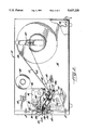
- FIG. 1 is a perspective view of a printing apparatus according to the present invention which is partially cut-away to illustrate the internal components thereof.
- FIG. 2 is a lateral cross-sectional view of the printing apparatus illustrated in FIG. 1.
- FIG. 3 is a front cross-sectional view of the printing apparatus of the present invention taken along line 3--3 of FIG. 2.
- FIG. 4 is a lateral cross-sectional view of a portion of the printing apparatus of the present invention illustrating the positioning of the print head in a raised or inoperative position.
- FIG. 5 is a perspective view of a portion of the printing apparatus of the present invention illustrating the platen and stripping rollers as well as the biasing of the stripping roller outwardly against the endless belt.
- FIG. 6 is a perspective view of a portion of the printing apparatus of the present invention illustrating the endless belt and its associated rollers and print head.
- the printing apparatus 10 is adapted to print indicia on one side of a strip of labels 12, each of which has an adhesive backing on one side.
- the printing apparatus 10 of the present invention includes an endless belt 14 rotatably mounted to a frame 16 so as to define an endless path of travel.
- the endless path of travel includes an upper delivery run 18 and a lower return run 20.
- the upper delivery run 18 defines, in turn, an upstream end 18a and a downstream end 18b.
- the printing apparatus 10 also includes means for advancing the endless belt 14 along the endless path of travel in a direction such that the upper delivery run 18 moves from the upstream end 18a to the downstream end 18b.
- the advancing means may include a drive motor 22 operably connected to the endless belt 14.
- the rotational energy supplied by the drive motor 22 is coupled, via a drive belt to the endless belt 14 so as to advance the belt about its endless path of travel.
- the endless belt 14 is preferably mounted about a plurality of rollers. As is best illustrated in FIGS. 2 and 4, a platen 26 is mounted within the endless belt 14. Although the platen 26 is illustrated as a roller, the platen may also be platform mounted within the endless belt 14. In addition, a stripping roller 28, drive roller 30 and platform roller 32 are also preferably mounted within the endless belt 14. As will be subsequently discussed in greater detail, the platform 32 facilitates the loading of the label strip 12 in the printing apparatus 10 and the stripping roller 28 facilitates the removal of the printed labels from the printing apparatus 10.
- the drive roller 30 is operably connected to the advancing means, such as the drive motor 22, so as to advance the belt 14.
- the drive belt 24 of the embodiment illustrated in FIGS. 2 and 4 is wrapped about the drive shaft 23 of the drive motor 22 as well as the drive roller 30.
- the rotation of the drive shaft 23 is imparted, via the drive belt 24, to rotate the drive roller 30 and, in turn, to advance the endless belt 14 about its endless path of travel.
- the drive belt 24 may also wrap about and rotate the platen roller 26 which also advances the endless belt 14.
- the printing apparatus 10 may also include a backup roller 34 which contacts the endless belt 14 and is aligned from the drive roller 30 on the opposite side of the endless belt 14.
- the backup roller 34 is preferably biased against the endless belt 14 and the underlying drive roller 30 to improve the contact of the drive roller 30 with the belt such that substantially all rotation of the drive roller 30 imparted by the circulating drive belt 24 is imparted to advance the endless belt 14.
- the backup roller 34 is typically carried by first and second arms which extend from a rotatable rod 40 mounted on the support frame 16.
- the rotatable rod 40 carries a spring 42 which urges the backup roller 34 downward against the endless belt 14.
- a first end of the backup roller bias spring 42 is held in a fixed position while the second end urges the first arm 36, and thus the backup roller 34 against the endless belt 14 and the underlying drive roller 30.
- the printing apparatus 10 of the present invention also includes means for printing indicia on one side of the label strip 12.
- the printing means includes a print head 44 positioned in alignment with the platen 26.
- the upper delivery run 18 of the endless belt 14, as well as the label strip 12 carried by the upper delivery run 18, extends between the print head 44 and the platen 26.
- the print head 44 may be adapted to print the labels according to any of the known methods of printing including serial dot matrix, direct thermal, thermal transfer, laser, line matrix, ink jet or impact full form printing as well as other electrographic printing methods.
- the print head 44 is adapted to provide direct thermal or thermal transfer printing as is known to those skilled in the art.
- a ribbon 46 coated with an inked material extends between the print head 44 and the label strip 12 such that selective heating of ribbon 46 by the print head 44 will imprint the desired indicia on the label 12.
- the ribbon 46 is typically drawn from a ribbon supply reel 48, is passed between the print head 44 and the underlying label 12 and is collected by a ribbon rewind reel 50.
- the printing apparatus 10 also preferably includes a stripping roller 28 mounted within the endless belt 14 at the downstream end 18b of the upper delivery run 18.
- the stripping roller 28 preferably has a relatively small radius as compared to the radius of the platen roller 26.
- the platen roller 26 preferably has an outer radius of at least about one-quarter (1/4) inch while the stripping roller 28 has an outer radius between about one-sixteenth (1/16) inch to one-eighth (1/8) inch.
- the sizes of stripping roller 28 and the platen 26 will generally be larger.
- the stripping roller 28 will still preferably have a relatively small radius as compared to the radius of the platen roller 26.
- the relatively small radius of the stripping roller 28 causes the endless belt 14 to be sharply turned as it advances about the stripping roller 28.
- the sharp turning of the endless belt 14 releases the label strip 12 from the upper delivery run 18 at the downstream end 18b thereof.
- the endless belt 14 encircles a substantial portion of the peripheral surface of the stripping roller 28 which further facilitates the release of the label strip 12 from the endless belt 14.
- the stripping roller 28 is sized and positioned so that the endless belt 14 contacts an arc of at least about 90° about preferably 120° the peripheral surface of the stripping roller 28. Most preferably, the endless belt 14 contacts an arc of at least about 120° about the peripheral surface of the stripping roller.
- the printing apparatus 10 preferably includes means for biasing the stripping roller 28 outwardly against the endless belt 14.
- the endless belt 14 is stretched taut about the stripping roller 28 and platen 26.
- the means for outwardly biasing the stripping roller 28 includes a spring 52 having a first end held in a fixed position relative to the support frame 16 and the endless belt 14 and a second end which engages and urges the stripping roller 28 outwardly against the endless belt 14.
- the strength of the spring 52 By varying the strength of the spring 52, the amount of outward bias supplied by the stripping roller 28 to the endless belt 14 may be adjusted.
- the platform roller 32 may be biased outwardly against the endless belt 14 in a similar manner to that described above with respect to the stripping roller 28 to stretch the endless belt 14 taut.
- the printing apparatus 10 also preferably includes means for biasing the print head 44 against the endless belt 14 and the underlying platen 26.
- the means for biasing the print head 44 maintains printing contact between the print head 44 and the label strip 12 which is advanced between the print head 44 and the platen 26.
- the print head 44 may be held in two positions, namely, a first or operative position and a second or raised position. The first or operative position of the print head 44 is illustrated in FIG. 2 in which printing contact is maintained between the print head 44 and the label strip 12. The second or raised position is shown in FIG. 4.
- the means for biasing the print head 44 against the endless belt 14 preferably include a pair of cams 54 which contacts an upper surface of the print head 44.
- the cams 54 are preferably mounted upon a rod 56 which, in turn, is rotatably mounted to the support frame 16.
- the rod 56 may be rotated between first and second positions.
- the cam 54 exerts a downward force on the print head 44 so as to bias the print head 44 against the endless belt 14 and the underlying platen 26.
- an upward or lifting force is applied by the cam 54 to the print head 44 so as to lift the print head from printing contact with the label strip 12.
- the platen 26 includes an outer peripheral layer 57 of resilient material to further enhance the print quality.
- the force exerted by the print head 44 against the endless belt 14 and the underlying platen 26 compresses a portion of the outer layer 57 of the platen 26 to form a relatively flat printing surface on the portion of the platen 26 contacting the endless belt 14.
- the printing apparatus 10 of the present invention is particularly adapted from printing indicia on labels.
- the labels 12 may be supplied in a wound roll 58.
- the wound roll 58 is preferably rotatably supported by a holder 60 which, in turn, is mounted to the support frame 16 or housing of the printing apparatus 10.
- the adhesive backed label strip 12 is thereafter advanced via a feed mechanism past the print head 44 for printing the predetermined indicia thereon.
- the printed labels 12 may be withdrawn from the printing apparatus 10 and separated from adjacent labels by the operator.
- the label strip 12 typically consists of a primary substrate which has an adhesive backing 62 on one side for attachment to an envelope or package once the predetermined indicia has been imprinted on the side of the label opposite the adhesive backing.
- the label strip 12 is characterized in that, unlike conventional label strips, the label strips 12 which the printing apparatus 10 in the present invention is particularly adapted to process are not mounted upon a carrier web. Instead, the side of the label strip 12 opposite the adhesive backing is coated with a release agent, such as silicone. Accordingly, the adhesive will not adhere adjacent label strips together and the label strip 12 may be drawn from the wound roll 58.
- the printing apparatus 10 of the present invention may also print other forms of media, including two-ply and multi-part forms. These forms may also be supplied in a wound roll and may be fed through the printing apparatus 10 such that indicia is imprinted thereon.
- the endless belt 14 preferably includes a substrate which is coated with a release material. Since the adhesive backed labels are placed upon and transported by the endless belt 14, the endless belt 14 does not significantly adhere to the adhesive backing 62 of the labels. Thus, the coating of the endless belt 14 may be formed of silicone which does not significantly adhere to the adhesive backing 62 of the labels. Alternatively, the endless belt 14 may be formed of a fabric, such as polyester, which is coated with a release agent, such as silicone.
- the endless belt 14 is preferably relatively thin and, more preferably, has a thickness of less than about 1/32 of an inch. In one embodiment, the endless belt 14 has width greater than the width of the labels 12. In an alternative embodiment, the endless belt 14 may be comprised of a plurality of parallel belts which are mounted upon the rollers such that the lateral portions of adjacent belts abut. In this embodiment, the cumulative width of the parallel belts is preferably greater than the width of the labels 12.
- the information to be imprinted via the print head 44 may be provided to the printing apparatus 10 of the present invention according to any of the known methods.
- the information to be imprinted may be provided via a data interface 66 from a source, such as a computer system, to a system controller 68.
- the system controller 68 is operably connected to the print head 44 and transmits signals thereto indicative of the particular indicia to be imprinted and the order and timing of the printing.
- the information or indicia to be imprinted upon the labels may be entered by the operator via a keypad 70 which is operably connected to the print head 44 for providing the control and timing signals necessary to print the desired information on the labels.
- other methods of providing the printing apparatus be with the predetermined information or indicia to be imprinted on the labels are known to those skilled in the art and may be utilized.
- the label strip 12 is delivered, such as from the wound roll 58 as illustrated in FIGS. 1 and 2, to the upstream end 18a of the upper delivery run 18 of the endless belt 14.
- the label strip 12 is preferably delivered to an upwardly exposed portion of the upper run of the endless belt 14 between the platform roller 32 and the drive roller 30. Delivery of the label strip 12 is facilitated by guide means, such as the guide 72 illustrated in FIGS. 2 and 6.
- the guide 72 is carried by the rotatable rod 40 and is semi-circular in transverse cross-section to assist in loading the label strip 12. As shown, the label strip 12 is fed between the guide 72 and the endless belt 14.
- the backup roller 34 and print head 44 must be raised from the surface of the endless belt 14 as shown in FIG. 4.
- the rotatable rod 40 which carries the backup roller 34 and the rod 56 which carries the print head 44 are connected, such as via connecting rod 74, such that both the backup roller 34 and the print head 44 are raised and lowered simultaneously. Accordingly, the operator may raise both the backup roller 34 and the print head 44 by rotating rod 56 with handle 76 so as to permit loading of the label strip 12 in the printing apparatus 10.
- the printing apparatus 10 includes means for controlling the advancement of the endless belt 14 and the feeding of the label strip 12 between the print head 44 and the platen 26.
- the label strip 12 is only advanced once the individual labels which have already been fed between the print head 44 and the platen 26 have been separated from the remainder of the label strip.
- the controlling means therefore prevents a large number of printed labels from accumulating.
- the means for controlling the advancement of the endless belt 14 includes means for detecting that the individual labels fed between the print head 44 and the platen 26 and released from the endless belt 14 at the downstream end 18b thereof have been separated from the remainder of the label strip 12.
- the detecting means may include any detecting means known to those skilled in the art, including an optical sensor 78 such as that illustrated in FIGS. 1 and 3.
- the optical sensor 78 is operably connected to the advancing means such that the endless belt 14 is permitted to be advanced once the individual labels have been separated from the remainder of the label strip 12.
- the printing apparatus 10 may also include means for controlling the registry or alignment of the label strip with the print head.
- the alignment controlling means also preferably includes means for detecting the position of the individual labels.
- the position detecting means is positioned upstream of the print head 44 and is operably connected to the means for advancing endless belt 14 such that the label strip 12 and the print head 44 may be aligned.
- the position detecting means may also be any type of detecting means known to those skilled in the art, including an optical sensor 80 as illustrated in FIG. 2.
- the label strip 12 for use in conjunction with optical detectors, such as those illustrated in FIG. 2, includes a plurality of longitudinally spaced apart marks 82 on the adhesive backed side of the label strip 12.
- a mark 82 is preferably positioned in a predetermined relationship with the individual labels. For example, a mark 82 may be located between adjacent labels.
- Optical sensor 80 is adapted to sense the marks 82 on the label strip 12 such that the label strip 12 and the print head 44 are aligned.
- the optical sensors 78 and 80 may be position downstream of and upstream of the endless belt 14, respectively.
- the optical sensors 78 and 80 may be mounted in different locations within the printing apparatus 10 or only a single sensor may be employed without departing from the spirit and scope of the invention.
- one or both optical sensors may be positioned within the endless belt 14.
- the endless belt 14 is preferably translucent or transparent to permit detection of the marks 82 therethrough.
- an adhesive backed label strip 12 may be advanced along in an endless belt 14 such that indicia may be imprinted on one side of the label strip 12 and the label strip 12 may be withdrawn from the endless belt 14 at the downstream end 18b thereof.
- the printing apparatus 10 of the present invention permits printing of label strips which are not mounted upon a carrier web so as to decrease the media cost of the labels. Further, the printing apparatus 10 of the present invention facilitates ready removable of the label strip 12 from the downstream end 18b of the endless belt 14.
Abstract
Description
Claims (29)
Priority Applications (1)
| Application Number | Priority Date | Filing Date | Title |
|---|---|---|---|
| US08/180,050 US5437228A (en) | 1994-01-11 | 1994-01-11 | Method and apparatus for printing adhesive backed media |
Applications Claiming Priority (1)
| Application Number | Priority Date | Filing Date | Title |
|---|---|---|---|
| US08/180,050 US5437228A (en) | 1994-01-11 | 1994-01-11 | Method and apparatus for printing adhesive backed media |
Publications (1)
| Publication Number | Publication Date |
|---|---|
| US5437228A true US5437228A (en) | 1995-08-01 |
Family
ID=22659031
Family Applications (1)
| Application Number | Title | Priority Date | Filing Date |
|---|---|---|---|
| US08/180,050 Expired - Lifetime US5437228A (en) | 1994-01-11 | 1994-01-11 | Method and apparatus for printing adhesive backed media |
Country Status (1)
| Country | Link |
|---|---|
| US (1) | US5437228A (en) |
Cited By (26)
| Publication number | Priority date | Publication date | Assignee | Title |
|---|---|---|---|---|
| US5531853A (en) * | 1994-10-31 | 1996-07-02 | Booth Manufacturing Company | Linerless label applicator |
| WO1997015501A1 (en) * | 1995-10-23 | 1997-05-01 | Moore Business Forms, Inc. | Linerless label dispenser |
| US5779370A (en) * | 1996-02-20 | 1998-07-14 | Premark Feg L.L.C. | Apparatus for printing labels and a self-releasing print roller therefor |
| US5832827A (en) * | 1995-06-07 | 1998-11-10 | Moore Business Forms, Inc. | Method for printing upon lenerless thermal transfer labels having a silicone release agent |
| US5940107A (en) * | 1995-01-09 | 1999-08-17 | Intermec Corporation | Method and apparatus for printing on a linerless media using a temporary liner in the print zone |
| US5978004A (en) * | 1997-03-31 | 1999-11-02 | Zebra Technologies Corporation | Label printer with label edge sensor |
| US6053231A (en) * | 1995-03-23 | 2000-04-25 | Osaka Sealing Printing Co., Ltd. | Bonding apparatus for cutting label continuum having labels formed thereon and bonding label to object |
| US6129810A (en) * | 1995-10-17 | 2000-10-10 | Moore Business Forms, Inc. | Linerless label dispenser |
| US6145436A (en) * | 1999-04-27 | 2000-11-14 | Astro-Med, Inc. | Label transport shuttle for a printing device |
| US6145423A (en) * | 1995-09-15 | 2000-11-14 | Moore Business Forms, Inc. | Semi-automatic dispenser for linerless labels |
| US6210515B1 (en) | 1995-02-27 | 2001-04-03 | Moore Business Forms, Inc. | Linerless label printer control |
| US6383631B1 (en) | 2000-04-17 | 2002-05-07 | The Standard Register Company | Release coating and barrier coating for linerless thermal labels and method of making |
| US6537406B1 (en) | 2000-04-03 | 2003-03-25 | 3M Innovative Properties Company | Vacuum-assisted tape applicator |
| US20030124345A1 (en) * | 1998-12-09 | 2003-07-03 | 3M Innovative Properties Company | Variably printed tape and system for printing and applying tape onto surfaces |
| US20030192639A1 (en) * | 2002-04-12 | 2003-10-16 | 3M Innovative Properties Company | Apparatus for printing and applying tape and methods of printing and applying tape |
| US6652172B2 (en) | 2001-01-05 | 2003-11-25 | 3M Innovative Properties Company | Method and apparatus for handling linerless label tape within a printing device |
| US6668892B2 (en) | 1999-06-11 | 2003-12-30 | 3M Innovative Properties Company | System for printing and applying tape onto surfaces |
| US20050019081A1 (en) * | 2003-07-25 | 2005-01-27 | 3M Innovative Properties Company | Apparatus and method for handling linerless label tape |
| US20050190368A1 (en) * | 2004-01-30 | 2005-09-01 | Zebra Technologies Corporation | Self calibrating media edge sensor |
| US20060004677A1 (en) * | 2004-06-30 | 2006-01-05 | Mattern James M | System for portable franking services |
| US20060280541A1 (en) * | 2005-05-31 | 2006-12-14 | Lass Robert E Jr | Printer and method for supporting a linerless label |
| US8435634B2 (en) | 2011-01-25 | 2013-05-07 | Linda J. Harwood | Fabric batting tape |
| JP2014024282A (en) * | 2012-07-27 | 2014-02-06 | Ricoh Co Ltd | Apparatus and method for forming image |
| US20140105661A1 (en) * | 2012-10-06 | 2014-04-17 | Ricoh Company, Ltd. | Image forming apparatus |
| US20150077459A1 (en) * | 2013-09-17 | 2015-03-19 | Norikazu YANASE | Image forming apparatus and method which controls a power of adsorption which holds a printing medium |
| US11259946B2 (en) | 2012-02-23 | 2022-03-01 | Covidien Lp | Luminal stenting |
Citations (10)
| Publication number | Priority date | Publication date | Assignee | Title |
|---|---|---|---|---|
| US2326436A (en) * | 1941-06-19 | 1943-08-10 | Oliver Machinery Co | Label attaching machine |
| US4073234A (en) * | 1975-04-26 | 1978-02-14 | Kabushiki Kaisha Sato Kenkyusho | Printing machine for label strip, or the like |
| JPS5634458A (en) * | 1979-08-30 | 1981-04-06 | Multi Giken Kk | Transfer press |
| US4262591A (en) * | 1978-12-18 | 1981-04-21 | Robert C. Cook | Office label printer and dispenser |
| US4384525A (en) * | 1980-09-05 | 1983-05-24 | Kabushiki Kaisha Sato | Code plate device for label printing and applying machines or the like |
| US4650350A (en) * | 1984-02-23 | 1987-03-17 | Kunz Ag | Method and apparatus for thermal printing of plastic cards |
| US4707211A (en) * | 1986-02-10 | 1987-11-17 | Ricoh Electronics, Inc. | Linerless thermal label printer and applicator |
| US5026180A (en) * | 1987-12-22 | 1991-06-25 | Victor Company Of Japan, Ltd. | Thermal ink-transfer printer capable of preventing off-registration of colors at color printing |
| US5060009A (en) * | 1988-10-26 | 1991-10-22 | Caisse Regional De Credit Agricole Mutuel De L'yonne | Method and apparatus for the automated image formation on any photographic media |
| US5069564A (en) * | 1989-11-20 | 1991-12-03 | Brother Kogyo Kabushiki Kaisha | Printing system |
-
1994
- 1994-01-11 US US08/180,050 patent/US5437228A/en not_active Expired - Lifetime
Patent Citations (10)
| Publication number | Priority date | Publication date | Assignee | Title |
|---|---|---|---|---|
| US2326436A (en) * | 1941-06-19 | 1943-08-10 | Oliver Machinery Co | Label attaching machine |
| US4073234A (en) * | 1975-04-26 | 1978-02-14 | Kabushiki Kaisha Sato Kenkyusho | Printing machine for label strip, or the like |
| US4262591A (en) * | 1978-12-18 | 1981-04-21 | Robert C. Cook | Office label printer and dispenser |
| JPS5634458A (en) * | 1979-08-30 | 1981-04-06 | Multi Giken Kk | Transfer press |
| US4384525A (en) * | 1980-09-05 | 1983-05-24 | Kabushiki Kaisha Sato | Code plate device for label printing and applying machines or the like |
| US4650350A (en) * | 1984-02-23 | 1987-03-17 | Kunz Ag | Method and apparatus for thermal printing of plastic cards |
| US4707211A (en) * | 1986-02-10 | 1987-11-17 | Ricoh Electronics, Inc. | Linerless thermal label printer and applicator |
| US5026180A (en) * | 1987-12-22 | 1991-06-25 | Victor Company Of Japan, Ltd. | Thermal ink-transfer printer capable of preventing off-registration of colors at color printing |
| US5060009A (en) * | 1988-10-26 | 1991-10-22 | Caisse Regional De Credit Agricole Mutuel De L'yonne | Method and apparatus for the automated image formation on any photographic media |
| US5069564A (en) * | 1989-11-20 | 1991-12-03 | Brother Kogyo Kabushiki Kaisha | Printing system |
Cited By (38)
| Publication number | Priority date | Publication date | Assignee | Title |
|---|---|---|---|---|
| US5531853A (en) * | 1994-10-31 | 1996-07-02 | Booth Manufacturing Company | Linerless label applicator |
| US5940107A (en) * | 1995-01-09 | 1999-08-17 | Intermec Corporation | Method and apparatus for printing on a linerless media using a temporary liner in the print zone |
| US6387203B1 (en) | 1995-02-27 | 2002-05-14 | Moore Business Forms, Inc. | Linerless label printer control |
| US6210515B1 (en) | 1995-02-27 | 2001-04-03 | Moore Business Forms, Inc. | Linerless label printer control |
| US6053231A (en) * | 1995-03-23 | 2000-04-25 | Osaka Sealing Printing Co., Ltd. | Bonding apparatus for cutting label continuum having labels formed thereon and bonding label to object |
| US5832827A (en) * | 1995-06-07 | 1998-11-10 | Moore Business Forms, Inc. | Method for printing upon lenerless thermal transfer labels having a silicone release agent |
| US6145423A (en) * | 1995-09-15 | 2000-11-14 | Moore Business Forms, Inc. | Semi-automatic dispenser for linerless labels |
| US6129810A (en) * | 1995-10-17 | 2000-10-10 | Moore Business Forms, Inc. | Linerless label dispenser |
| WO1997015501A1 (en) * | 1995-10-23 | 1997-05-01 | Moore Business Forms, Inc. | Linerless label dispenser |
| EP0874774A4 (en) * | 1996-02-20 | 2001-01-10 | Premark Feg Llc | Apparatus for printing labels and a self-releasing print roller therefor |
| EP0874774A1 (en) * | 1996-02-20 | 1998-11-04 | Premark Feg L.L.C. | Apparatus for printing labels and a self-releasing print roller therefor |
| US5779370A (en) * | 1996-02-20 | 1998-07-14 | Premark Feg L.L.C. | Apparatus for printing labels and a self-releasing print roller therefor |
| US5978004A (en) * | 1997-03-31 | 1999-11-02 | Zebra Technologies Corporation | Label printer with label edge sensor |
| US20030124345A1 (en) * | 1998-12-09 | 2003-07-03 | 3M Innovative Properties Company | Variably printed tape and system for printing and applying tape onto surfaces |
| US6145436A (en) * | 1999-04-27 | 2000-11-14 | Astro-Med, Inc. | Label transport shuttle for a printing device |
| US6668892B2 (en) | 1999-06-11 | 2003-12-30 | 3M Innovative Properties Company | System for printing and applying tape onto surfaces |
| US20030094233A1 (en) * | 2000-04-03 | 2003-05-22 | 3M Innovative Properties Company | Vacuum-assisted tape applicator |
| US6537406B1 (en) | 2000-04-03 | 2003-03-25 | 3M Innovative Properties Company | Vacuum-assisted tape applicator |
| US6383631B1 (en) | 2000-04-17 | 2002-05-07 | The Standard Register Company | Release coating and barrier coating for linerless thermal labels and method of making |
| US6652172B2 (en) | 2001-01-05 | 2003-11-25 | 3M Innovative Properties Company | Method and apparatus for handling linerless label tape within a printing device |
| US20030192639A1 (en) * | 2002-04-12 | 2003-10-16 | 3M Innovative Properties Company | Apparatus for printing and applying tape and methods of printing and applying tape |
| US6884312B2 (en) | 2002-04-12 | 2005-04-26 | 3M Innovative Properties Company | Apparatus for printing and applying tape and methods of printing and applying tape |
| US7220071B2 (en) | 2003-07-25 | 2007-05-22 | 3M Innovative Properties Company | Apparatus and method for handling linerless label tape |
| WO2005016653A2 (en) | 2003-07-25 | 2005-02-24 | 3M Innovative Properties Company | Apparatus and method for handling linerless label tape |
| US6910820B2 (en) | 2003-07-25 | 2005-06-28 | 3M Innovative Properties Company | Apparatus and method for handling linerless label tape |
| US20050019081A1 (en) * | 2003-07-25 | 2005-01-27 | 3M Innovative Properties Company | Apparatus and method for handling linerless label tape |
| US7391043B2 (en) | 2004-01-30 | 2008-06-24 | Zih Corp. | Self calibrating media edge sensor |
| US20050190368A1 (en) * | 2004-01-30 | 2005-09-01 | Zebra Technologies Corporation | Self calibrating media edge sensor |
| US20080203335A1 (en) * | 2004-01-30 | 2008-08-28 | Zih Corporation | Self calibrating media edge sensor |
| US20060004677A1 (en) * | 2004-06-30 | 2006-01-05 | Mattern James M | System for portable franking services |
| US20060280541A1 (en) * | 2005-05-31 | 2006-12-14 | Lass Robert E Jr | Printer and method for supporting a linerless label |
| US8435634B2 (en) | 2011-01-25 | 2013-05-07 | Linda J. Harwood | Fabric batting tape |
| US11259946B2 (en) | 2012-02-23 | 2022-03-01 | Covidien Lp | Luminal stenting |
| JP2014024282A (en) * | 2012-07-27 | 2014-02-06 | Ricoh Co Ltd | Apparatus and method for forming image |
| US20140105661A1 (en) * | 2012-10-06 | 2014-04-17 | Ricoh Company, Ltd. | Image forming apparatus |
| US9110424B2 (en) * | 2012-10-06 | 2015-08-18 | Ricoh Company, Ltd. | Image forming apparatus forming an image on adhesive face of print medium |
| US20150077459A1 (en) * | 2013-09-17 | 2015-03-19 | Norikazu YANASE | Image forming apparatus and method which controls a power of adsorption which holds a printing medium |
| US9233560B2 (en) * | 2013-09-17 | 2016-01-12 | Ricoh Company, Ltd. | Image forming apparatus and method which controls a power of adsorption which holds a printing medium |
Similar Documents
| Publication | Publication Date | Title |
|---|---|---|
| US5437228A (en) | Method and apparatus for printing adhesive backed media | |
| US5718525A (en) | label printer and dispenser | |
| US5487337A (en) | Method and apparatus for printing linerless media having an adhesive backing | |
| US5497701A (en) | Method and apparatus for printing linerless media having an adhesive backing | |
| US7220071B2 (en) | Apparatus and method for handling linerless label tape | |
| US4375189A (en) | Label printer | |
| US9266355B2 (en) | Method of producing printed labels | |
| JPS5942985A (en) | Mark detecting apparatus in printer | |
| JPH07172006A (en) | Printer and printing method for liner-less label | |
| JP2004516962A (en) | Apparatus and method for handling linerless label tape in a printing device | |
| AU2009204733A1 (en) | Labelling machine | |
| JPS621891B2 (en) | ||
| JP4473354B2 (en) | Labeling device | |
| JP4167327B2 (en) | Labeling device | |
| JP2961482B2 (en) | Automatic labeling equipment | |
| JPH05221436A (en) | Label feeder | |
| JP2531511B2 (en) | Ribbon meandering prevention device for transfer type thermal printer | |
| JP2000281029A (en) | Device for printing and cutting label without mount | |
| CN115042521A (en) | Printer for coiled material | |
| JPH08276923A (en) | Price tag printing device | |
| JPH11171152A (en) | Labeling device | |
| JP2000019971A (en) | Tack label and apparatus for production therefor | |
| JP2003165516A (en) | Automatic-feed heat-sensitive labeler, and automatically feeding and affixing method of heat-sensitive labeler | |
| JPH0479945B2 (en) | ||
| JPH0129151B2 (en) |
Legal Events
| Date | Code | Title | Description |
|---|---|---|---|
| AS | Assignment |
Owner name: DATASOUTH CORPORATION, NORTH CAROLINA Free format text: ASSIGNMENT OF ASSIGNORS INTEREST;ASSIGNOR:ULAND, DAVID M.;REEL/FRAME:006900/0823 Effective date: 19940314 |
|
| AS | Assignment |
Owner name: DATASOUTH COMPUTER CORPORATION, NORTH CAROLINA Free format text: CORECTIVE ASSIGNMENT TO CORRECT THE NAME OF THE ASSIGNEE PREVIOUSLY RECORDED AT REEL 6900 FRAME 823.;ASSIGNOR:ULAND, DAVID M.;REEL/FRAME:007066/0456 Effective date: 19940714 |
|
| STCF | Information on status: patent grant |
Free format text: PATENTED CASE |
|
| FPAY | Fee payment |
Year of fee payment: 4 |
|
| REFU | Refund |
Free format text: REFUND - PAYMENT OF MAINTENANCE FEE, 8TH YR, SMALL ENTITY (ORIGINAL EVENT CODE: R2552); ENTITY STATUS OF PATENT OWNER: LARGE ENTITY |
|
| FPAY | Fee payment |
Year of fee payment: 8 |
|
| REMI | Maintenance fee reminder mailed | ||
| FPAY | Fee payment |
Year of fee payment: 12 |