US5436508A - Wind-powered energy production and storing system - Google Patents
Wind-powered energy production and storing system Download PDFInfo
- Publication number
- US5436508A US5436508A US08/081,373 US8137393A US5436508A US 5436508 A US5436508 A US 5436508A US 8137393 A US8137393 A US 8137393A US 5436508 A US5436508 A US 5436508A
- Authority
- US
- United States
- Prior art keywords
- wind
- energy production
- powered energy
- storing
- wind wheel
- Prior art date
- Legal status (The legal status is an assumption and is not a legal conclusion. Google has not performed a legal analysis and makes no representation as to the accuracy of the status listed.)
- Expired - Fee Related
Links
Images


Classifications
-
- F—MECHANICAL ENGINEERING; LIGHTING; HEATING; WEAPONS; BLASTING
- F28—HEAT EXCHANGE IN GENERAL
- F28D—HEAT-EXCHANGE APPARATUS, NOT PROVIDED FOR IN ANOTHER SUBCLASS, IN WHICH THE HEAT-EXCHANGE MEDIA DO NOT COME INTO DIRECT CONTACT
- F28D20/00—Heat storage plants or apparatus in general; Regenerative heat-exchange apparatus not covered by groups F28D17/00 or F28D19/00
- F28D20/0056—Heat storage plants or apparatus in general; Regenerative heat-exchange apparatus not covered by groups F28D17/00 or F28D19/00 using solid heat storage material
-
- F—MECHANICAL ENGINEERING; LIGHTING; HEATING; WEAPONS; BLASTING
- F03—MACHINES OR ENGINES FOR LIQUIDS; WIND, SPRING, OR WEIGHT MOTORS; PRODUCING MECHANICAL POWER OR A REACTIVE PROPULSIVE THRUST, NOT OTHERWISE PROVIDED FOR
- F03D—WIND MOTORS
- F03D13/00—Assembly, mounting or commissioning of wind motors; Arrangements specially adapted for transporting wind motor components
- F03D13/20—Arrangements for mounting or supporting wind motors; Masts or towers for wind motors
- F03D13/22—Foundations specially adapted for wind motors
-
- F—MECHANICAL ENGINEERING; LIGHTING; HEATING; WEAPONS; BLASTING
- F03—MACHINES OR ENGINES FOR LIQUIDS; WIND, SPRING, OR WEIGHT MOTORS; PRODUCING MECHANICAL POWER OR A REACTIVE PROPULSIVE THRUST, NOT OTHERWISE PROVIDED FOR
- F03D—WIND MOTORS
- F03D15/00—Transmission of mechanical power
-
- F—MECHANICAL ENGINEERING; LIGHTING; HEATING; WEAPONS; BLASTING
- F03—MACHINES OR ENGINES FOR LIQUIDS; WIND, SPRING, OR WEIGHT MOTORS; PRODUCING MECHANICAL POWER OR A REACTIVE PROPULSIVE THRUST, NOT OTHERWISE PROVIDED FOR
- F03D—WIND MOTORS
- F03D15/00—Transmission of mechanical power
- F03D15/20—Gearless transmission, i.e. direct-drive
-
- F—MECHANICAL ENGINEERING; LIGHTING; HEATING; WEAPONS; BLASTING
- F03—MACHINES OR ENGINES FOR LIQUIDS; WIND, SPRING, OR WEIGHT MOTORS; PRODUCING MECHANICAL POWER OR A REACTIVE PROPULSIVE THRUST, NOT OTHERWISE PROVIDED FOR
- F03D—WIND MOTORS
- F03D9/00—Adaptations of wind motors for special use; Combinations of wind motors with apparatus driven thereby; Wind motors specially adapted for installation in particular locations
- F03D9/10—Combinations of wind motors with apparatus storing energy
- F03D9/18—Combinations of wind motors with apparatus storing energy storing heat
-
- F—MECHANICAL ENGINEERING; LIGHTING; HEATING; WEAPONS; BLASTING
- F03—MACHINES OR ENGINES FOR LIQUIDS; WIND, SPRING, OR WEIGHT MOTORS; PRODUCING MECHANICAL POWER OR A REACTIVE PROPULSIVE THRUST, NOT OTHERWISE PROVIDED FOR
- F03D—WIND MOTORS
- F03D9/00—Adaptations of wind motors for special use; Combinations of wind motors with apparatus driven thereby; Wind motors specially adapted for installation in particular locations
- F03D9/20—Wind motors characterised by the driven apparatus
- F03D9/22—Wind motors characterised by the driven apparatus the apparatus producing heat
-
- F—MECHANICAL ENGINEERING; LIGHTING; HEATING; WEAPONS; BLASTING
- F03—MACHINES OR ENGINES FOR LIQUIDS; WIND, SPRING, OR WEIGHT MOTORS; PRODUCING MECHANICAL POWER OR A REACTIVE PROPULSIVE THRUST, NOT OTHERWISE PROVIDED FOR
- F03D—WIND MOTORS
- F03D9/00—Adaptations of wind motors for special use; Combinations of wind motors with apparatus driven thereby; Wind motors specially adapted for installation in particular locations
- F03D9/20—Wind motors characterised by the driven apparatus
- F03D9/28—Wind motors characterised by the driven apparatus the apparatus being a pump or a compressor
-
- F—MECHANICAL ENGINEERING; LIGHTING; HEATING; WEAPONS; BLASTING
- F28—HEAT EXCHANGE IN GENERAL
- F28D—HEAT-EXCHANGE APPARATUS, NOT PROVIDED FOR IN ANOTHER SUBCLASS, IN WHICH THE HEAT-EXCHANGE MEDIA DO NOT COME INTO DIRECT CONTACT
- F28D20/00—Heat storage plants or apparatus in general; Regenerative heat-exchange apparatus not covered by groups F28D17/00 or F28D19/00
- F28D2020/006—Heat storage systems not otherwise provided for
-
- Y—GENERAL TAGGING OF NEW TECHNOLOGICAL DEVELOPMENTS; GENERAL TAGGING OF CROSS-SECTIONAL TECHNOLOGIES SPANNING OVER SEVERAL SECTIONS OF THE IPC; TECHNICAL SUBJECTS COVERED BY FORMER USPC CROSS-REFERENCE ART COLLECTIONS [XRACs] AND DIGESTS
- Y02—TECHNOLOGIES OR APPLICATIONS FOR MITIGATION OR ADAPTATION AGAINST CLIMATE CHANGE
- Y02E—REDUCTION OF GREENHOUSE GAS [GHG] EMISSIONS, RELATED TO ENERGY GENERATION, TRANSMISSION OR DISTRIBUTION
- Y02E10/00—Energy generation through renewable energy sources
- Y02E10/70—Wind energy
- Y02E10/72—Wind turbines with rotation axis in wind direction
-
- Y—GENERAL TAGGING OF NEW TECHNOLOGICAL DEVELOPMENTS; GENERAL TAGGING OF CROSS-SECTIONAL TECHNOLOGIES SPANNING OVER SEVERAL SECTIONS OF THE IPC; TECHNICAL SUBJECTS COVERED BY FORMER USPC CROSS-REFERENCE ART COLLECTIONS [XRACs] AND DIGESTS
- Y02—TECHNOLOGIES OR APPLICATIONS FOR MITIGATION OR ADAPTATION AGAINST CLIMATE CHANGE
- Y02E—REDUCTION OF GREENHOUSE GAS [GHG] EMISSIONS, RELATED TO ENERGY GENERATION, TRANSMISSION OR DISTRIBUTION
- Y02E10/00—Energy generation through renewable energy sources
- Y02E10/70—Wind energy
- Y02E10/728—Onshore wind turbines
-
- Y—GENERAL TAGGING OF NEW TECHNOLOGICAL DEVELOPMENTS; GENERAL TAGGING OF CROSS-SECTIONAL TECHNOLOGIES SPANNING OVER SEVERAL SECTIONS OF THE IPC; TECHNICAL SUBJECTS COVERED BY FORMER USPC CROSS-REFERENCE ART COLLECTIONS [XRACs] AND DIGESTS
- Y02—TECHNOLOGIES OR APPLICATIONS FOR MITIGATION OR ADAPTATION AGAINST CLIMATE CHANGE
- Y02E—REDUCTION OF GREENHOUSE GAS [GHG] EMISSIONS, RELATED TO ENERGY GENERATION, TRANSMISSION OR DISTRIBUTION
- Y02E60/00—Enabling technologies; Technologies with a potential or indirect contribution to GHG emissions mitigation
- Y02E60/14—Thermal energy storage
-
- Y—GENERAL TAGGING OF NEW TECHNOLOGICAL DEVELOPMENTS; GENERAL TAGGING OF CROSS-SECTIONAL TECHNOLOGIES SPANNING OVER SEVERAL SECTIONS OF THE IPC; TECHNICAL SUBJECTS COVERED BY FORMER USPC CROSS-REFERENCE ART COLLECTIONS [XRACs] AND DIGESTS
- Y02—TECHNOLOGIES OR APPLICATIONS FOR MITIGATION OR ADAPTATION AGAINST CLIMATE CHANGE
- Y02E—REDUCTION OF GREENHOUSE GAS [GHG] EMISSIONS, RELATED TO ENERGY GENERATION, TRANSMISSION OR DISTRIBUTION
- Y02E60/00—Enabling technologies; Technologies with a potential or indirect contribution to GHG emissions mitigation
- Y02E60/16—Mechanical energy storage, e.g. flywheels or pressurised fluids
-
- Y—GENERAL TAGGING OF NEW TECHNOLOGICAL DEVELOPMENTS; GENERAL TAGGING OF CROSS-SECTIONAL TECHNOLOGIES SPANNING OVER SEVERAL SECTIONS OF THE IPC; TECHNICAL SUBJECTS COVERED BY FORMER USPC CROSS-REFERENCE ART COLLECTIONS [XRACs] AND DIGESTS
- Y02—TECHNOLOGIES OR APPLICATIONS FOR MITIGATION OR ADAPTATION AGAINST CLIMATE CHANGE
- Y02E—REDUCTION OF GREENHOUSE GAS [GHG] EMISSIONS, RELATED TO ENERGY GENERATION, TRANSMISSION OR DISTRIBUTION
- Y02E70/00—Other energy conversion or management systems reducing GHG emissions
- Y02E70/30—Systems combining energy storage with energy generation of non-fossil origin
Definitions
- the invention relates to a wind-powered energy production and storing system, comprising a wind rotor of a compact structure in driving engagement with a power generator via transmission means, to which is also connected a heat pump for operation of at least one heat exchanger unit.
- the objective of the invention is to provide a wind energy, system which is suited for simultaneous production of power and heat energy with a relatively high efficiency, in which a cold storing station is connected to the storing system for production of cold, and the heat energy by being stored can be used for power production in periods of slack winds.
- a further objective of the invention is to vide a plant of the above-mentioned type with a comparatively simple, robust and compact structure, well suited for being erected in isolated areas where access to energy supply from the outside is non-existent or poor.
- a wind-powered energy production and storing system is characterized in that the wind rotor is designed as a wind wheel having a rim in direct driving engagement with a main shaft positioned in a subjacent engine housing to which main shaft, in addition to the power generator and said heat pump, a dual circulation pump is coupled for conveying heated and cooled liquid from a heating container and a cooling container, respectively, positioned in the engine housing to separate heat and cold storing stations.
- the separate heat and cold storing stations may be designed as, e.g. sand-filled energy storages buried in soil and insulated.
- the output can be improved by using not only liquid as heating and cooling medium, respectively, but also air which is discharged from a blower positioned in the engine housing with temperature regulated air discharge either to the heat storing station or the cold storing station.
- an automatic gale protection device may be connected to the wind rotor, designed as an oil pump coupled to the main shaft which via a hydraulic activator can activate a gale protection device which is spring-loaded in the normal operational condition of the wind wheel and which turns the wind wheel out of the wind if a certain wind velocity is exceeded.
- FIG. 1 is a principal diagram illustrating an embodiment of a wind energy system according to the invention
- FIGS. 2 and 3 show an embodiment of the rotor structure
- FIGS. 4 and 5 show further details of the gale protection device
- FIGS. 6 to 8 show further details of the design of a blade of the rotor structure
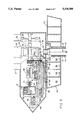
- FIG. 9 shows the engine housing of the rotor structure with transmission means and units run by same
- FIG. 10 is a schematic diagram of the conveyance of heating and cooling medium between the engine housing and separate heat and cold storing stations.
- the rotor structure comprises a blade wheel 1 suspended in a fork 2, which is firmly fastened to a subjacent engine housing 3, in which the rim flange of the blade wheel 1 drives a main shaft as described in the following.
- the subjacent engine housing 3 is pivotally journalled on the top of a pipe foundation 5 by means of a revolving ring 4, and above the blade wheel 1 the fork support 2 passes through a top bearing 6 for connection with a steering rudder 7 with gale fins 8.
- the rotor structure is stabilized by means of a wire system with wires 9 and 10, which from the top bearing 6 and the upper part of the pipe foundation 5, respectively, at the revolving ring 4 are routed to poles or posts 11.
- Cable and pipe connections 12, 13, 14 and 15 are routed through the pipe foundation 5 from the engine housing 3 via the revolving ring 4 for conveyance of electricity, and heat and cold carrying media to separate energy storages buried in soil, comprising a heat storing station 16, a boiler station or steam generator 17 and a cold storing station 18.
- a steam turbine 19 with a coupled-up generator 20 is connected to the boiler station 17 for production of electricity in periods of slack winds.
- the heat storing station 16 and the boiler station 17 are energywise connected via a steam separator 21 and a pump 22.
- the wind wheel 1 has a large number of blades 23, e.g. 32, which are fixed between a hub 24 pivotally journalled in the fork support 2 and the rim flange 25 of the wheel. As shown at 26 in this embodiment the latter is provided with a toothed rim which in the engine housing 3 is in engagement with a smooth-running roller coupling 28 connected with the main shaft 27.
- the rim flange 25 of the wind wheel 1 may be provided with a friction layer which drives a rubber wheel positioned on the main shaft, e.g. a twin wheel.
- the angle is typically 60 degrees.
- the rudder 7 Under normal wind conditions the rudder 7 will ensure that the wind wheel 1 is turned so that it is at right angles to the wind direction marked by an arrow 36. This position is stabilized by means of a spring 37, which from the connecting point of the rudder 7 and the rods 30, 31 extends inwards and downwards towards the fork support.
- the spring 37 is connected to a pull wire 38 which via reversing rollers 39 and 40 passes through the pipe section 35 and further along one leg of the fork support 2 down to the engine housing.
- each of the blades 23 can be made of a folded rectangular metal sheet, e.g. stainless steel sheet folded along the lines 23a-23f shown in FIG. 6.
- the sail is terminated by, e.g. a U-shaped bracket 23g, which by means of a number of bolts is fastened to, e.g. a T-shaped bracket 23h, welded to the underside of the rim flange, whereas the other end of the blade passes through an oval hole 24a in the hub 24 and is fastened by means of a nut.
- a power generator 39 is coupled up to the main shaft 27 in the engine housing 3, which supplies power to consumer installations not shown, and excess power is routed to the heat storing station 16 via a cable 40 to a slip ring 67 and through the cable 12 in the pipe foundation 5.
- a dual heat pump 42 is connected to the main shaft 27 via a coupling 41, which together with a heating container 43 and a cooling container 44 form part of closed heating and cooling circuits.
- a heating/cooling liquid By compression of the heating/cooling liquid it is routed through a pipe line 45 to the heating container 43 where it gives off heat to the water volume contained therein.
- the liquid is routed through the pipe line 46 for nozzle atomization in the cooling container 44, whereby the coolant contained therein is cooled.
- the heating and cooling containers 43 and 44 are via pipe lines 47 and 48 connected to respectively sections 49a, 49b of a dual circulation pump 49 which is run by the main shaft 27 via a belt drive. Heating and cooling liquid is routed from the circulation pump 49 through outlet pipes 51 and 52 to separate transfer chambers 53 and 54 which are connected with pipe lines 13 and 14 in the pipe foundation. Return flow pipes 55' and 56' for heating and cooling media are routed from separate transfer chambers 55 and 56 to an additional circulation pump 49'.
- the engine housing 3 is pivotally supported on the pipe foundation by means of the revolving ring or the main bearing 4.
- the transfer chambers 53-56 are designed as concentric cylindrical chambers in an almost basin-shaped container 68 fastened around the bearing 4 on the pipe foundation 5, in which the chambers 53-56 are separated by means of heat-insulated partition walls 69, 70 and 71, at the top provided with rubber packings not shown.
- the top of the container 68 with the walls 69-71 is covered by a lid 72 which is connected to the engine housing 3 for co-rotation therewith, for example by having carriers projecting downwards from the underside of the engine housing, engaging catching members on the lid 72 so that a certain relative angular rotation is allowed, e.g. 20°.
- the lid is provided with connecting pieces for outlet pipes 51 and 52 and the return pipes 55' and 56', e.g. designed as tube connections leading to and from the circulation pumps 49, 49'.
- the pull wire 38 shown in dotted line is via a reversing roller 57 in the engine housing 3 wound around a roller 58 connected to the piston of an hydraulic actuator 59 which via a membrane regulator 61 can be activated by means of an oil pump 60 which is run by the main shaft 27 via a belt drive 62.
- the pull wire is routed from the roller 58 via a further reversing roller 63 into the pipe foundation 5 to a manually operated winch 64, by means of which the length of the pull wire can be adjusted.
- the actuator 59 is affected via the membrane regulator 61 and exerts a pull on the part of the pull wire 38 which runs upwards along the fork support 2 to the rudder 7.
- the pull wire 38 will then turn the rudder 7 around the oblique hinge 32.
- the efficient function of the gale protection is thereby threefold ensured, as it is activated immediately at too high wind velocity, and in part because it is actuated via the hydraulic activator at too high a rate of rotation of the main shaft of the engine housing, and partly can be ensured mechanically by means of the winch 64.
- a blower 65 with air suction through a grating at one end wall of the engine housing 3 may be connected to the main shaft 27.
- the displaced engine air can thereby be routed to the energy stations 16-18 via the pipe line 15 through the pipe foundation 5 and a thermostat-adjusted distributor device 66.
- the engine housing is provided with not shown bearings and braking devices for the main shaft as well as suspension means and other accessories.
- the separate energy storages 16, 17 and 18 may as already mentioned be designed as storages buried in soil, e.g. in the form of elliptical depressions with heat-insulated linings 73 of mineral wool or a similar material and with a filling 74 of dry sand, gravel, stones or similar materials as shown in FIG. 10.
- the pipes 13 for heat carrying medium are routed to a transfer unit 75, from which a pipe or tube 76 is routed to the steam separator 21, from which a connection 78 from a lower level is routed through the heat storing station 16 back to the transfer unit 75.
- a water discharge 79 leads via the pump 22 and a thermostat-controlled valve 81 to the bottom of the steam generator or the boiler station 17 and through this via a tube 82 to the steam turbine 19, which runs the power generator 20 supplying power via the cable 88.
- the discharge pipe 89 from the steam turbine is routed through the heat storing station 16 to the bottom of the steam separator 21.
- Excess pressure air from the steam separator 21 may be routed through a pipe 91 to an expansion tank not shown which is provided with a safety valve.
- the valve 81 is adjusted so that it, e.g. closes off the inlet to the steam generator 17 when the temperature falls below 120°, whereby the steam turbine 19 is disconnected via a pressure valve.
- the electrical control may for example consist in a solenoid valve being arranged in the connection 79 between the steam separator 21 and the pump 22, said valve being kept closed while the voltage in the electrical grid to which the system is connected has its normal stable value, but is opened by a spring when the solenoid valve is deactivated whereby steam production to the turbine 19 may begin when the pressure in the steam separator 21 and thereby the temperature are sufficiently high to open the valve 81.
- Not shown adjustment members for number of revolutions and steam supply may be provided for the steam turbine 19 as well as not shown control and adjustment members for the generator 20 for adjustment of the power supplied by same.
- the cooling medium from the cooling container 44 in the engine housing 3 is routed through the pipe 14 to the cold storing station 18 from where it can be tapped and used for cooling purposes such as, e.g. freezing or air conditioning via a secondary circuit not shown.
- blower 65 By means of the blower 65 both heating and air can be routed through the pipe 15 in the pipe foundation 5 to the transfer unit 66, from which point pipes have been routed through the heat storing station 16 with the steam separator 21, the steam generator 17 and the cold storing station 18, respectively.
Abstract
Description
Claims (15)
Applications Claiming Priority (3)
| Application Number | Priority Date | Filing Date | Title |
|---|---|---|---|
| DK233/91 | 1991-02-12 | ||
| DK023391A DK23391D0 (en) | 1991-02-12 | 1991-02-12 | WINDOW FOR SELF-SUPPLY AND STORAGE OF ENERGY |
| PCT/DK1992/000044 WO1992014054A1 (en) | 1991-02-12 | 1992-02-12 | A wind-powered energy production and storing system |
Publications (1)
| Publication Number | Publication Date |
|---|---|
| US5436508A true US5436508A (en) | 1995-07-25 |
Family
ID=8091235
Family Applications (1)
| Application Number | Title | Priority Date | Filing Date |
|---|---|---|---|
| US08/081,373 Expired - Fee Related US5436508A (en) | 1991-02-12 | 1992-02-12 | Wind-powered energy production and storing system |
Country Status (8)
| Country | Link |
|---|---|
| US (1) | US5436508A (en) |
| EP (1) | EP0571486B1 (en) |
| AT (1) | ATE119972T1 (en) |
| AU (1) | AU657733B2 (en) |
| CA (1) | CA2101628A1 (en) |
| DE (1) | DE69201723T2 (en) |
| DK (2) | DK23391D0 (en) |
| WO (1) | WO1992014054A1 (en) |
Cited By (58)
| Publication number | Priority date | Publication date | Assignee | Title |
|---|---|---|---|---|
| WO2000068570A1 (en) * | 1999-05-07 | 2000-11-16 | Neg Micon A/S | An offshore wind turbine with liquid-cooling |
| US20030105556A1 (en) * | 2001-10-05 | 2003-06-05 | Enis Ben M. | Method and apparatus for using wind turbines to generate and supply uninterrupted power to locations remote from the power grid |
| GB2384528A (en) * | 2001-11-01 | 2003-07-30 | Thomas John Mcneel Robertson | wind-power device for buildings |
| US6664655B2 (en) * | 2001-12-31 | 2003-12-16 | Charles S. Vann | Multaxel windmill |
| US20040267466A1 (en) * | 2001-10-05 | 2004-12-30 | Enis Ben M. | Method of coordinating and stabilizing the delivery of wind generated energy |
| US6876101B1 (en) * | 1999-11-24 | 2005-04-05 | Jordan Knez | Device for transducing of power |
| EP1577549A1 (en) * | 2004-03-16 | 2005-09-21 | Abb Research Ltd. | Apparatus for storing thermal energy and generating electricity |
| EP1577548A1 (en) * | 2004-03-16 | 2005-09-21 | Abb Research Ltd. | Apparatus and method for storing thermal energy and generating electricity |
| US20060089805A1 (en) * | 2001-10-05 | 2006-04-27 | Enis Ben M | Method of coordinating and stabilizing the delivery of wind generated energy |
| US20060110687A1 (en) * | 2004-11-05 | 2006-05-25 | Kenji Kawano | Pattern forming method and a semiconductor device manufacturing method |
| US20070102938A1 (en) * | 2005-11-04 | 2007-05-10 | Poole A B | Infuser augmented vertical wind turbine electrical generating system |
| US20070166159A1 (en) * | 2006-01-17 | 2007-07-19 | Williams Herbert L | Wind turbine |
| US20070220889A1 (en) * | 2004-07-23 | 2007-09-27 | Nayef Durald S | Electric Power Plant With Thermal Storage Medium |
| US20090033102A1 (en) * | 2007-07-30 | 2009-02-05 | Enis Ben M | Method and apparatus for using wind turbines to generate and supply uninterrupted power to locations remote from the power grid |
| US20090094981A1 (en) * | 2007-10-12 | 2009-04-16 | General Electric Company | Wind turbine geothermal heating and cooling system |
| US20090208334A1 (en) * | 2008-02-15 | 2009-08-20 | Wind Simplicity Inc. | Wind Flap Brake Assembly for Wind Turbine |
| US20100181770A1 (en) * | 2009-01-16 | 2010-07-22 | Brickett Benjamin P | Method and Apparatus for Fluid Turbine having a Linear Actuator |
| US20110018269A1 (en) * | 2009-07-21 | 2011-01-27 | George Moser | Wind turbine |
| US7900444B1 (en) | 2008-04-09 | 2011-03-08 | Sustainx, Inc. | Systems and methods for energy storage and recovery using compressed gas |
| US7958731B2 (en) | 2009-01-20 | 2011-06-14 | Sustainx, Inc. | Systems and methods for combined thermal and compressed gas energy conversion systems |
| US7963110B2 (en) | 2009-03-12 | 2011-06-21 | Sustainx, Inc. | Systems and methods for improving drivetrain efficiency for compressed gas energy storage |
| US7974742B2 (en) | 2003-06-13 | 2011-07-05 | Enis Ben M | Method of coordinating and stabilizing the delivery of wind generated energy |
| US8037678B2 (en) | 2009-09-11 | 2011-10-18 | Sustainx, Inc. | Energy storage and generation systems and methods using coupled cylinder assemblies |
| US20110254283A1 (en) * | 2009-01-13 | 2011-10-20 | Vestas Wind Systems A/S | wind turbine |
| US8046990B2 (en) | 2009-06-04 | 2011-11-01 | Sustainx, Inc. | Systems and methods for improving drivetrain efficiency for compressed gas energy storage and recovery systems |
| WO2012003021A1 (en) * | 2010-07-01 | 2012-01-05 | Twin Disc, Inc. | Power generator using a wind turbine, a hydrodynamic retarder, and an organic rankine cycle drive |
| US8104274B2 (en) | 2009-06-04 | 2012-01-31 | Sustainx, Inc. | Increased power in compressed-gas energy storage and recovery |
| US8117842B2 (en) | 2009-11-03 | 2012-02-21 | Sustainx, Inc. | Systems and methods for compressed-gas energy storage using coupled cylinder assemblies |
| US20120104770A1 (en) * | 2010-10-29 | 2012-05-03 | Jacob Sajan Joseph | Regenerative power charging for electricity generation systems |
| US8171728B2 (en) | 2010-04-08 | 2012-05-08 | Sustainx, Inc. | High-efficiency liquid heat exchange in compressed-gas energy storage systems |
| US8191362B2 (en) | 2010-04-08 | 2012-06-05 | Sustainx, Inc. | Systems and methods for reducing dead volume in compressed-gas energy storage systems |
| US8225606B2 (en) | 2008-04-09 | 2012-07-24 | Sustainx, Inc. | Systems and methods for energy storage and recovery using rapid isothermal gas expansion and compression |
| US8234863B2 (en) | 2010-05-14 | 2012-08-07 | Sustainx, Inc. | Forming liquid sprays in compressed-gas energy storage systems for effective heat exchange |
| US8240140B2 (en) | 2008-04-09 | 2012-08-14 | Sustainx, Inc. | High-efficiency energy-conversion based on fluid expansion and compression |
| US8240146B1 (en) | 2008-06-09 | 2012-08-14 | Sustainx, Inc. | System and method for rapid isothermal gas expansion and compression for energy storage |
| US8250863B2 (en) | 2008-04-09 | 2012-08-28 | Sustainx, Inc. | Heat exchange with compressed gas in energy-storage systems |
| US8359856B2 (en) | 2008-04-09 | 2013-01-29 | Sustainx Inc. | Systems and methods for efficient pumping of high-pressure fluids for energy storage and recovery |
| EP2574740A1 (en) | 2011-09-29 | 2013-04-03 | Siemens Aktiengesellschaft | Assembly for storing thermal energy |
| EP2574738A1 (en) | 2011-09-29 | 2013-04-03 | Siemens Aktiengesellschaft | Assembly for storing thermal energy |
| EP2574865A1 (en) | 2011-09-29 | 2013-04-03 | Siemens Aktiengesellschaft | Energy storage device and energy storage method |
| EP2574739A1 (en) | 2011-09-29 | 2013-04-03 | Siemens Aktiengesellschaft | Assembly for storing thermal energy and method for its operation |
| US8448433B2 (en) | 2008-04-09 | 2013-05-28 | Sustainx, Inc. | Systems and methods for energy storage and recovery using gas expansion and compression |
| DE102011088380A1 (en) | 2011-12-13 | 2013-06-13 | Siemens Aktiengesellschaft | Energy storage device with open charging circuit for storing seasonal excess electrical energy |
| US8474255B2 (en) | 2008-04-09 | 2013-07-02 | Sustainx, Inc. | Forming liquid sprays in compressed-gas energy storage systems for effective heat exchange |
| US8479505B2 (en) | 2008-04-09 | 2013-07-09 | Sustainx, Inc. | Systems and methods for reducing dead volume in compressed-gas energy storage systems |
| US8495872B2 (en) | 2010-08-20 | 2013-07-30 | Sustainx, Inc. | Energy storage and recovery utilizing low-pressure thermal conditioning for heat exchange with high-pressure gas |
| US8539763B2 (en) | 2011-05-17 | 2013-09-24 | Sustainx, Inc. | Systems and methods for efficient two-phase heat transfer in compressed-air energy storage systems |
| DE102012206296A1 (en) | 2012-04-17 | 2013-10-17 | Siemens Aktiengesellschaft | Plant for storage and delivery of thermal energy and method of operation thereof |
| EP2653668A1 (en) | 2012-04-17 | 2013-10-23 | Siemens Aktiengesellschaft | Method for loading and discharging a heat exchanger and assembly for storing and discharging thermal energy suitable for this method |
| EP2653670A1 (en) | 2012-04-17 | 2013-10-23 | Siemens Aktiengesellschaft | Assembly for storing and emitting thermal energy with a heat storage device and a cold air reservoir and method for its operation |
| US8578708B2 (en) | 2010-11-30 | 2013-11-12 | Sustainx, Inc. | Fluid-flow control in energy storage and recovery systems |
| EP2698505A1 (en) | 2012-08-14 | 2014-02-19 | Siemens Aktiengesellschaft | Method for loading and discharging a heat exchanger and assembly for storing and discharging thermal energy suitable for this method |
| US8667792B2 (en) | 2011-10-14 | 2014-03-11 | Sustainx, Inc. | Dead-volume management in compressed-gas energy storage and recovery systems |
| US8677744B2 (en) | 2008-04-09 | 2014-03-25 | SustaioX, Inc. | Fluid circulation in energy storage and recovery systems |
| WO2014044549A2 (en) | 2012-09-24 | 2014-03-27 | Siemens Aktiengesellschaft | Method for charging and discharging a storage medium in a heat accumulator and system for performing said method |
| US8739533B2 (en) | 2010-12-02 | 2014-06-03 | Or Yogev | Solar augmented wind turbine for stable and dispatchable utility scale power generation |
| US8966902B2 (en) | 2010-07-12 | 2015-03-03 | Siemens Aktiengesellschaft | Storage and recovery of thermal energy based on counter current principle of heat transfer medium transportation |
| US20190162167A1 (en) * | 2016-06-08 | 2019-05-30 | Adolfo Gonzalez Perez | Autonomous sustainable wind unit, multi-blade reticular rotor, energy accumulator and energy converter and uses |
Families Citing this family (9)
| Publication number | Priority date | Publication date | Assignee | Title |
|---|---|---|---|---|
| US5384489A (en) * | 1994-02-07 | 1995-01-24 | Bellac; Alphonse H. | Wind-powered electricity generating system including wind energy storage |
| WO2007134466A1 (en) * | 2006-05-24 | 2007-11-29 | Abb Research Ltd | Thermoelectric energy storage system and method for storing thermoelectric energy |
| DE102006028810A1 (en) * | 2006-06-21 | 2008-02-21 | Daubner & Stommel GbR Bau-Werk-Planung (vertretungsberechtigter Gesellschafter: Matthias Stommel, 27777 Ganderkesee) | Method for operating a wind energy plant |
| DE102009005985A1 (en) * | 2009-01-23 | 2010-08-05 | G.A.M. Holding Gmbh | Combined wind energy and heat storage system for use in residential buildings, has wind rotor, heat accumulator filled with heat storage medium, particularly water, and heating generator driven by wind rotor |
| CN102971600A (en) | 2010-07-12 | 2013-03-13 | 西门子公司 | Thermal energy storage and recovery device and system having a heat exchanger arrangement using a compressed gas |
| EP2593742A2 (en) | 2010-07-12 | 2013-05-22 | Siemens Aktiengesellschaft | Thermal energy storage and recovery with a heat exchanger arrangement having an extended thermal interaction region |
| FR2965341B1 (en) * | 2010-09-27 | 2014-11-28 | Areva Solar Inc | FLUID FOR MEDIUM STORAGE SYSTEM FOR HIGH TEMPERATURE WATER VAPOR |
| ES2539643B1 (en) * | 2013-10-21 | 2016-01-26 | Adolfo GONZÁLEZ PÉREZ | Autonomous wind turbine with energy accumulation and applications |
| CN112502747B (en) * | 2020-09-30 | 2022-08-23 | 同济大学 | Tunnel anti-freezing and warm-keeping device and method based on wind energy heating and application |
Citations (9)
| Publication number | Priority date | Publication date | Assignee | Title |
|---|---|---|---|---|
| DE371459C (en) * | 1921-11-13 | 1923-03-15 | Paul Wagner | Impeller for wind turbines with closed channels on all sides, which are arranged in several concentrically arranged rings provided with blades |
| US2329675A (en) * | 1941-12-22 | 1943-09-14 | Wincharger Corp | Auxiliary wind electric system for prime movers |
| DE2812465A1 (en) * | 1978-03-22 | 1979-09-27 | Erich Herter | Wind turbine with horizontal shaft - is mounted on vertical mast to be adjustable in height to suit wind conditions |
| US4206608A (en) * | 1978-06-21 | 1980-06-10 | Bell Thomas J | Natural energy conversion, storage and electricity generation system |
| US4230531A (en) * | 1977-03-03 | 1980-10-28 | Fernandopulle Placidus D | Wind powered solar still |
| DE3008327A1 (en) * | 1980-03-05 | 1981-09-17 | Heinrich Dipl.-Ing. 7022 Leinfelden-Echterdingen List | Wind-powered direct heat energy generator - uses fluidic eddy brake or throttled pump system |
| DE3210405A1 (en) * | 1982-03-22 | 1983-09-22 | Gar, Konrad, 8017 Ebersberg | Wind wheel for generating wind power, in particular for low-wind areas |
| DE3231496A1 (en) * | 1982-08-25 | 1984-03-08 | Emil 4401 Laer Molzan | Wind power machine having an automatically operating storm safety device |
| US4787819A (en) * | 1987-12-07 | 1988-11-29 | Bond Michael G A | Windmill device |
Family Cites Families (8)
| Publication number | Priority date | Publication date | Assignee | Title |
|---|---|---|---|---|
| DE459035C (en) * | 1928-04-25 | Aero Dynamo Akt Ges | Tubular mast for wind turbines | |
| US2136857A (en) * | 1936-04-16 | 1938-11-15 | Massoni Miguel | Windmill |
| DE952250C (en) * | 1950-03-03 | 1956-11-15 | Ludwig Bening | Wind turbine with automatic storm protection |
| FR1037243A (en) * | 1951-05-18 | 1953-09-15 | Bladed rotor | |
| SE385613B (en) * | 1974-10-17 | 1976-07-12 | Svenska Platror Ab | FACILITY FOR MEDIUM WIND ENERGY ALSTRA HOT WATER |
| SE400112B (en) * | 1976-05-10 | 1978-03-13 | Boestad Gustav Karl William | DEVICE FOR WIND POWER PLANT WITH HYDRAULICLY MANUFACTURED WINGS |
| DE2759476C2 (en) * | 1977-04-07 | 1980-12-18 | Franz Xaver Prof. Dr.- Ing. 7030 Boeblingen Wortmann | Rotor tower with wind power machine arranged in the tower head |
| SE415911B (en) * | 1979-08-07 | 1980-11-10 | Assar Nordebo | Control, regulating and storm protection device for a horizontal wind power plant |
-
1991
- 1991-02-12 DK DK023391A patent/DK23391D0/en not_active Application Discontinuation
-
1992
- 1992-02-12 CA CA002101628A patent/CA2101628A1/en not_active Abandoned
- 1992-02-12 US US08/081,373 patent/US5436508A/en not_active Expired - Fee Related
- 1992-02-12 AT AT92905218T patent/ATE119972T1/en not_active IP Right Cessation
- 1992-02-12 WO PCT/DK1992/000044 patent/WO1992014054A1/en active IP Right Grant
- 1992-02-12 EP EP92905218A patent/EP0571486B1/en not_active Expired - Lifetime
- 1992-02-12 AU AU12698/92A patent/AU657733B2/en not_active Ceased
- 1992-02-12 DK DK92905218.1T patent/DK0571486T3/en active
- 1992-02-12 DE DE69201723T patent/DE69201723T2/en not_active Expired - Fee Related
Patent Citations (9)
| Publication number | Priority date | Publication date | Assignee | Title |
|---|---|---|---|---|
| DE371459C (en) * | 1921-11-13 | 1923-03-15 | Paul Wagner | Impeller for wind turbines with closed channels on all sides, which are arranged in several concentrically arranged rings provided with blades |
| US2329675A (en) * | 1941-12-22 | 1943-09-14 | Wincharger Corp | Auxiliary wind electric system for prime movers |
| US4230531A (en) * | 1977-03-03 | 1980-10-28 | Fernandopulle Placidus D | Wind powered solar still |
| DE2812465A1 (en) * | 1978-03-22 | 1979-09-27 | Erich Herter | Wind turbine with horizontal shaft - is mounted on vertical mast to be adjustable in height to suit wind conditions |
| US4206608A (en) * | 1978-06-21 | 1980-06-10 | Bell Thomas J | Natural energy conversion, storage and electricity generation system |
| DE3008327A1 (en) * | 1980-03-05 | 1981-09-17 | Heinrich Dipl.-Ing. 7022 Leinfelden-Echterdingen List | Wind-powered direct heat energy generator - uses fluidic eddy brake or throttled pump system |
| DE3210405A1 (en) * | 1982-03-22 | 1983-09-22 | Gar, Konrad, 8017 Ebersberg | Wind wheel for generating wind power, in particular for low-wind areas |
| DE3231496A1 (en) * | 1982-08-25 | 1984-03-08 | Emil 4401 Laer Molzan | Wind power machine having an automatically operating storm safety device |
| US4787819A (en) * | 1987-12-07 | 1988-11-29 | Bond Michael G A | Windmill device |
Non-Patent Citations (1)
| Title |
|---|
| Park, The Wind Power Book, 1981, p. 142. * |
Cited By (105)
| Publication number | Priority date | Publication date | Assignee | Title |
|---|---|---|---|---|
| US6520737B1 (en) | 1999-05-07 | 2003-02-18 | Neg Micon A/S | Offshore wind turbine with liquid-cooling |
| WO2000068570A1 (en) * | 1999-05-07 | 2000-11-16 | Neg Micon A/S | An offshore wind turbine with liquid-cooling |
| US6876101B1 (en) * | 1999-11-24 | 2005-04-05 | Jordan Knez | Device for transducing of power |
| US20040267466A1 (en) * | 2001-10-05 | 2004-12-30 | Enis Ben M. | Method of coordinating and stabilizing the delivery of wind generated energy |
| US20060232895A1 (en) * | 2001-10-05 | 2006-10-19 | Enis Ben M | Method and apparatus for using wind turbines to generate and supply uninterrupted power to locations remote from the power grid |
| US7250691B2 (en) | 2001-10-05 | 2007-07-31 | Enis Ben M | Method and apparatus for using wind turbines to generate and supply uninterrupted power to locations remote from the power grid |
| US6963802B2 (en) | 2001-10-05 | 2005-11-08 | Enis Ben M | Method of coordinating and stabilizing the delivery of wind generated energy |
| US7308361B2 (en) | 2001-10-05 | 2007-12-11 | Enis Ben M | Method of coordinating and stabilizing the delivery of wind generated energy |
| US6927503B2 (en) * | 2001-10-05 | 2005-08-09 | Ben M. Enis | Method and apparatus for using wind turbines to generate and supply uninterrupted power to locations remote from the power grid |
| US7067937B2 (en) | 2001-10-05 | 2006-06-27 | Enis Ben M | Method and apparatus for using wind turbines to generate and supply uninterrupted power to locations remote from the power grid |
| US20030105556A1 (en) * | 2001-10-05 | 2003-06-05 | Enis Ben M. | Method and apparatus for using wind turbines to generate and supply uninterrupted power to locations remote from the power grid |
| US20060089805A1 (en) * | 2001-10-05 | 2006-04-27 | Enis Ben M | Method of coordinating and stabilizing the delivery of wind generated energy |
| US20050225091A1 (en) * | 2001-10-05 | 2005-10-13 | Enis Ben M | Method and apparatus for using wind turbines to generate and supply uninterrupted power to locations remote from the power grid |
| GB2384528B (en) * | 2001-11-01 | 2004-06-09 | Thomas John Mcneel Robertson | Improvements in or relating to wind power devices for buildings |
| GB2384528A (en) * | 2001-11-01 | 2003-07-30 | Thomas John Mcneel Robertson | wind-power device for buildings |
| US6664655B2 (en) * | 2001-12-31 | 2003-12-16 | Charles S. Vann | Multaxel windmill |
| US7974742B2 (en) | 2003-06-13 | 2011-07-05 | Enis Ben M | Method of coordinating and stabilizing the delivery of wind generated energy |
| WO2005088122A1 (en) * | 2004-03-16 | 2005-09-22 | Abb Research Ltd | Apparatus and method for storing thermal energy and generating electricity |
| EP1577548A1 (en) * | 2004-03-16 | 2005-09-21 | Abb Research Ltd. | Apparatus and method for storing thermal energy and generating electricity |
| EP1577549A1 (en) * | 2004-03-16 | 2005-09-21 | Abb Research Ltd. | Apparatus for storing thermal energy and generating electricity |
| US20080022683A1 (en) * | 2004-03-16 | 2008-01-31 | Christian Ohler | Storing Thermal Energy and Generating Electricity |
| US20070220889A1 (en) * | 2004-07-23 | 2007-09-27 | Nayef Durald S | Electric Power Plant With Thermal Storage Medium |
| US20060110687A1 (en) * | 2004-11-05 | 2006-05-25 | Kenji Kawano | Pattern forming method and a semiconductor device manufacturing method |
| US20070102938A1 (en) * | 2005-11-04 | 2007-05-10 | Poole A B | Infuser augmented vertical wind turbine electrical generating system |
| US7230348B2 (en) | 2005-11-04 | 2007-06-12 | Poole A Bruce | Infuser augmented vertical wind turbine electrical generating system |
| US20070166159A1 (en) * | 2006-01-17 | 2007-07-19 | Williams Herbert L | Wind turbine |
| US7399162B2 (en) | 2006-01-17 | 2008-07-15 | Williams Herbert L | Wind turbine |
| US20090033102A1 (en) * | 2007-07-30 | 2009-02-05 | Enis Ben M | Method and apparatus for using wind turbines to generate and supply uninterrupted power to locations remote from the power grid |
| US20090094981A1 (en) * | 2007-10-12 | 2009-04-16 | General Electric Company | Wind turbine geothermal heating and cooling system |
| US20090208334A1 (en) * | 2008-02-15 | 2009-08-20 | Wind Simplicity Inc. | Wind Flap Brake Assembly for Wind Turbine |
| US8128363B2 (en) * | 2008-02-15 | 2012-03-06 | Wind Simplicity Inc. | Wind flap brake assembly for wind turbine |
| US8474255B2 (en) | 2008-04-09 | 2013-07-02 | Sustainx, Inc. | Forming liquid sprays in compressed-gas energy storage systems for effective heat exchange |
| US8448433B2 (en) | 2008-04-09 | 2013-05-28 | Sustainx, Inc. | Systems and methods for energy storage and recovery using gas expansion and compression |
| US8713929B2 (en) | 2008-04-09 | 2014-05-06 | Sustainx, Inc. | Systems and methods for energy storage and recovery using compressed gas |
| US8763390B2 (en) | 2008-04-09 | 2014-07-01 | Sustainx, Inc. | Heat exchange with compressed gas in energy-storage systems |
| US8677744B2 (en) | 2008-04-09 | 2014-03-25 | SustaioX, Inc. | Fluid circulation in energy storage and recovery systems |
| US8627658B2 (en) | 2008-04-09 | 2014-01-14 | Sustainx, Inc. | Systems and methods for energy storage and recovery using rapid isothermal gas expansion and compression |
| US8733095B2 (en) | 2008-04-09 | 2014-05-27 | Sustainx, Inc. | Systems and methods for efficient pumping of high-pressure fluids for energy |
| US8733094B2 (en) | 2008-04-09 | 2014-05-27 | Sustainx, Inc. | Systems and methods for energy storage and recovery using rapid isothermal gas expansion and compression |
| US8479505B2 (en) | 2008-04-09 | 2013-07-09 | Sustainx, Inc. | Systems and methods for reducing dead volume in compressed-gas energy storage systems |
| US8359856B2 (en) | 2008-04-09 | 2013-01-29 | Sustainx Inc. | Systems and methods for efficient pumping of high-pressure fluids for energy storage and recovery |
| US8250863B2 (en) | 2008-04-09 | 2012-08-28 | Sustainx, Inc. | Heat exchange with compressed gas in energy-storage systems |
| US8209974B2 (en) | 2008-04-09 | 2012-07-03 | Sustainx, Inc. | Systems and methods for energy storage and recovery using compressed gas |
| US7900444B1 (en) | 2008-04-09 | 2011-03-08 | Sustainx, Inc. | Systems and methods for energy storage and recovery using compressed gas |
| US8240140B2 (en) | 2008-04-09 | 2012-08-14 | Sustainx, Inc. | High-efficiency energy-conversion based on fluid expansion and compression |
| US8225606B2 (en) | 2008-04-09 | 2012-07-24 | Sustainx, Inc. | Systems and methods for energy storage and recovery using rapid isothermal gas expansion and compression |
| US8240146B1 (en) | 2008-06-09 | 2012-08-14 | Sustainx, Inc. | System and method for rapid isothermal gas expansion and compression for energy storage |
| US20110254283A1 (en) * | 2009-01-13 | 2011-10-20 | Vestas Wind Systems A/S | wind turbine |
| US8593010B2 (en) * | 2009-01-13 | 2013-11-26 | Vestas Wind Systems A/S | Wind turbine |
| US9309867B2 (en) * | 2009-01-16 | 2016-04-12 | Benjamin P. Brickett | Method and apparatus for fluid turbine having a linear actuator |
| US20100181770A1 (en) * | 2009-01-16 | 2010-07-22 | Brickett Benjamin P | Method and Apparatus for Fluid Turbine having a Linear Actuator |
| US8234862B2 (en) | 2009-01-20 | 2012-08-07 | Sustainx, Inc. | Systems and methods for combined thermal and compressed gas energy conversion systems |
| US8122718B2 (en) | 2009-01-20 | 2012-02-28 | Sustainx, Inc. | Systems and methods for combined thermal and compressed gas energy conversion systems |
| US7958731B2 (en) | 2009-01-20 | 2011-06-14 | Sustainx, Inc. | Systems and methods for combined thermal and compressed gas energy conversion systems |
| US8234868B2 (en) | 2009-03-12 | 2012-08-07 | Sustainx, Inc. | Systems and methods for improving drivetrain efficiency for compressed gas energy storage |
| US7963110B2 (en) | 2009-03-12 | 2011-06-21 | Sustainx, Inc. | Systems and methods for improving drivetrain efficiency for compressed gas energy storage |
| US8479502B2 (en) | 2009-06-04 | 2013-07-09 | Sustainx, Inc. | Increased power in compressed-gas energy storage and recovery |
| US8046990B2 (en) | 2009-06-04 | 2011-11-01 | Sustainx, Inc. | Systems and methods for improving drivetrain efficiency for compressed gas energy storage and recovery systems |
| US8104274B2 (en) | 2009-06-04 | 2012-01-31 | Sustainx, Inc. | Increased power in compressed-gas energy storage and recovery |
| US8482147B2 (en) | 2009-07-21 | 2013-07-09 | George Moser | Wind turbine with powered synchronization system |
| US20110018269A1 (en) * | 2009-07-21 | 2011-01-27 | George Moser | Wind turbine |
| US8468815B2 (en) | 2009-09-11 | 2013-06-25 | Sustainx, Inc. | Energy storage and generation systems and methods using coupled cylinder assemblies |
| US8037678B2 (en) | 2009-09-11 | 2011-10-18 | Sustainx, Inc. | Energy storage and generation systems and methods using coupled cylinder assemblies |
| US8109085B2 (en) | 2009-09-11 | 2012-02-07 | Sustainx, Inc. | Energy storage and generation systems and methods using coupled cylinder assemblies |
| US8117842B2 (en) | 2009-11-03 | 2012-02-21 | Sustainx, Inc. | Systems and methods for compressed-gas energy storage using coupled cylinder assemblies |
| US8191362B2 (en) | 2010-04-08 | 2012-06-05 | Sustainx, Inc. | Systems and methods for reducing dead volume in compressed-gas energy storage systems |
| US8245508B2 (en) | 2010-04-08 | 2012-08-21 | Sustainx, Inc. | Improving efficiency of liquid heat exchange in compressed-gas energy storage systems |
| US8661808B2 (en) | 2010-04-08 | 2014-03-04 | Sustainx, Inc. | High-efficiency heat exchange in compressed-gas energy storage systems |
| US8171728B2 (en) | 2010-04-08 | 2012-05-08 | Sustainx, Inc. | High-efficiency liquid heat exchange in compressed-gas energy storage systems |
| US8234863B2 (en) | 2010-05-14 | 2012-08-07 | Sustainx, Inc. | Forming liquid sprays in compressed-gas energy storage systems for effective heat exchange |
| WO2012003021A1 (en) * | 2010-07-01 | 2012-01-05 | Twin Disc, Inc. | Power generator using a wind turbine, a hydrodynamic retarder, and an organic rankine cycle drive |
| US8966902B2 (en) | 2010-07-12 | 2015-03-03 | Siemens Aktiengesellschaft | Storage and recovery of thermal energy based on counter current principle of heat transfer medium transportation |
| US8495872B2 (en) | 2010-08-20 | 2013-07-30 | Sustainx, Inc. | Energy storage and recovery utilizing low-pressure thermal conditioning for heat exchange with high-pressure gas |
| US20120104770A1 (en) * | 2010-10-29 | 2012-05-03 | Jacob Sajan Joseph | Regenerative power charging for electricity generation systems |
| US8578708B2 (en) | 2010-11-30 | 2013-11-12 | Sustainx, Inc. | Fluid-flow control in energy storage and recovery systems |
| US8739533B2 (en) | 2010-12-02 | 2014-06-03 | Or Yogev | Solar augmented wind turbine for stable and dispatchable utility scale power generation |
| US8539763B2 (en) | 2011-05-17 | 2013-09-24 | Sustainx, Inc. | Systems and methods for efficient two-phase heat transfer in compressed-air energy storage systems |
| US8806866B2 (en) | 2011-05-17 | 2014-08-19 | Sustainx, Inc. | Systems and methods for efficient two-phase heat transfer in compressed-air energy storage systems |
| EP2574738A1 (en) | 2011-09-29 | 2013-04-03 | Siemens Aktiengesellschaft | Assembly for storing thermal energy |
| WO2013045463A1 (en) | 2011-09-29 | 2013-04-04 | Siemens Aktiengesellschaft | Installation for storing thermal energy and method for the operation thereof |
| JP2014532138A (en) * | 2011-09-29 | 2014-12-04 | シーメンス アクティエンゲゼルシャフト | Equipment for storing thermal energy |
| US9829254B2 (en) | 2011-09-29 | 2017-11-28 | Siemens Aktiengesellschaft | Installation for storing thermal energy |
| EP2574740A1 (en) | 2011-09-29 | 2013-04-03 | Siemens Aktiengesellschaft | Assembly for storing thermal energy |
| EP2574865A1 (en) | 2011-09-29 | 2013-04-03 | Siemens Aktiengesellschaft | Energy storage device and energy storage method |
| WO2013045437A1 (en) | 2011-09-29 | 2013-04-04 | Siemens Aktiengesellschaft | Installation for storing electrical energy |
| WO2013045388A1 (en) | 2011-09-29 | 2013-04-04 | Siemens Aktiengesellschaft | Installation for storing thermal energy |
| WO2013045243A1 (en) | 2011-09-29 | 2013-04-04 | Siemens Aktiengesellschaft | Energy-storing device and method for storing energy |
| EP2574739A1 (en) | 2011-09-29 | 2013-04-03 | Siemens Aktiengesellschaft | Assembly for storing thermal energy and method for its operation |
| US8667792B2 (en) | 2011-10-14 | 2014-03-11 | Sustainx, Inc. | Dead-volume management in compressed-gas energy storage and recovery systems |
| US9322297B2 (en) | 2011-12-13 | 2016-04-26 | Siemens Aktiengesellschaft | Energy storage installation with open charging circuit for storing seasonally occurring excess electrical energy |
| DE102011088380A1 (en) | 2011-12-13 | 2013-06-13 | Siemens Aktiengesellschaft | Energy storage device with open charging circuit for storing seasonal excess electrical energy |
| WO2013087321A2 (en) | 2011-12-13 | 2013-06-20 | Siemens Aktiengesellschaft | Energy storage device with open charging circuit for storing seasonally occurring excess electrical energy |
| DE102012206296A1 (en) | 2012-04-17 | 2013-10-17 | Siemens Aktiengesellschaft | Plant for storage and delivery of thermal energy and method of operation thereof |
| WO2013156284A1 (en) | 2012-04-17 | 2013-10-24 | Siemens Aktiengesellschaft | System for storing and outputting thermal energy having a heat accumulator and a cold accumulator and method for the operation thereof |
| CN104271896A (en) * | 2012-04-17 | 2015-01-07 | 西门子公司 | Method for charging and discharging a heat accumulator and system for storing and outputting thermal energy, suitable for said method |
| WO2013156292A1 (en) | 2012-04-17 | 2013-10-24 | Siemens Aktiengesellschaft | System for storing and outputting thermal energy and method for operating said system |
| WO2013156291A1 (en) | 2012-04-17 | 2013-10-24 | Siemens Aktiengesellschaft | Method for charging and discharging a heat accumulator and system for storing and outputting thermal energy, suitable for said method |
| EP2653670A1 (en) | 2012-04-17 | 2013-10-23 | Siemens Aktiengesellschaft | Assembly for storing and emitting thermal energy with a heat storage device and a cold air reservoir and method for its operation |
| EP2653668A1 (en) | 2012-04-17 | 2013-10-23 | Siemens Aktiengesellschaft | Method for loading and discharging a heat exchanger and assembly for storing and discharging thermal energy suitable for this method |
| WO2014026863A2 (en) | 2012-08-14 | 2014-02-20 | Siemens Aktiengesellschaft | Method for charging and discharging a heat accumulator and system for storing and releasing thermal energy suitable for said method |
| EP2698505A1 (en) | 2012-08-14 | 2014-02-19 | Siemens Aktiengesellschaft | Method for loading and discharging a heat exchanger and assembly for storing and discharging thermal energy suitable for this method |
| DE102012217142A1 (en) | 2012-09-24 | 2014-03-27 | Siemens Aktiengesellschaft | A method for loading and unloading a storage medium in a heat storage and installation for carrying out this method |
| WO2014044549A2 (en) | 2012-09-24 | 2014-03-27 | Siemens Aktiengesellschaft | Method for charging and discharging a storage medium in a heat accumulator and system for performing said method |
| US20190162167A1 (en) * | 2016-06-08 | 2019-05-30 | Adolfo Gonzalez Perez | Autonomous sustainable wind unit, multi-blade reticular rotor, energy accumulator and energy converter and uses |
| EP3470667A4 (en) * | 2016-06-08 | 2020-03-04 | González Pérez, Adolfo | Autonomous sustainable wind unit, multi-blade reticular rotor, energy accumulator and energy converter and uses |
Also Published As
| Publication number | Publication date |
|---|---|
| DK0571486T3 (en) | 1995-05-29 |
| EP0571486A1 (en) | 1993-12-01 |
| DE69201723D1 (en) | 1995-04-20 |
| ATE119972T1 (en) | 1995-04-15 |
| AU657733B2 (en) | 1995-03-23 |
| DE69201723T2 (en) | 1995-10-19 |
| CA2101628A1 (en) | 1992-08-13 |
| AU1269892A (en) | 1992-09-07 |
| DK23391D0 (en) | 1991-02-12 |
| EP0571486B1 (en) | 1995-03-15 |
| WO1992014054A1 (en) | 1992-08-20 |
Similar Documents
| Publication | Publication Date | Title |
|---|---|---|
| US5436508A (en) | Wind-powered energy production and storing system | |
| US2539862A (en) | Air-driven turbine power plant | |
| US4369373A (en) | Method and apparatus for generating electricity from the flow of fluid through a well | |
| US4236083A (en) | Windmill having thermal and electric power output | |
| US7615884B2 (en) | Hybrid wind turbine system, apparatus and method | |
| US8938967B2 (en) | Hybrid wind turbine | |
| US4304103A (en) | Heat pump operated by wind or other power means | |
| US4496846A (en) | Power generation from wind | |
| US8587145B2 (en) | Vertical axis hydro kinetic wind turbine | |
| US20120138447A1 (en) | Solar desalination system with solar-initiated wind power pumps | |
| US8143740B1 (en) | Apparatus for storing and using wind energy | |
| AU2006319085A1 (en) | Machine for producing water from wind energy | |
| KR20230031369A (en) | FFWN Clean Energy Power Plant | |
| RU2305793C1 (en) | Small-size hydroelectric power station with action turbine | |
| US4286434A (en) | Solar power plant equipped with high efficiency heat exchangers | |
| US4307573A (en) | Thermal-cycle engine | |
| GB2448333A (en) | Turbine energy storage | |
| JP2006068575A (en) | Method and apparatus for aerating and circulating reservoir, and the like, by wind power energy | |
| RU2614451C1 (en) | Independent power source based on wind power installation | |
| JP2000291525A (en) | Power generating system | |
| WO2009090305A1 (en) | Method and plant for producing energy | |
| DE102019003254B4 (en) | ENERGY SYSTEM | |
| GB2615345A (en) | Apparatus for use in generating electricity | |
| RU2041388C1 (en) | Power plant | |
| SU1761860A1 (en) | Method of controlling water temperature in tail race of hydroelectric station and heat-exchange device therefor |
Legal Events
| Date | Code | Title | Description |
|---|---|---|---|
| AS | Assignment |
Owner name: SORENSON, ANNA MARGRETHE, DENMARK Free format text: ASSIGNMENT OF ASSIGNORS INTEREST;ASSIGNOR:SORENSON, JENS-RICHARD;REEL/FRAME:006747/0147 Effective date: 19930331 |
|
| AS | Assignment |
Owner name: SORENSEN, ANNA M., DENMARK Free format text: CORRECTIVE ASSIGNMENT TO CORRECT ASSIGNEE'S NAME PREVIOUSLY RECORDED AT REEL 6747, FRAME 147-;ASSIGNOR:SORENSEN, JENS-RICHARD;REEL/FRAME:006851/0275 Effective date: 19930331 |
|
| FPAY | Fee payment |
Year of fee payment: 4 |
|
| REMI | Maintenance fee reminder mailed | ||
| LAPS | Lapse for failure to pay maintenance fees | ||
| STCH | Information on status: patent discontinuation |
Free format text: PATENT EXPIRED DUE TO NONPAYMENT OF MAINTENANCE FEES UNDER 37 CFR 1.362 |
|
| FP | Lapsed due to failure to pay maintenance fee |
Effective date: 20030725 |