US5436409A - Electrical conductor member such as a wire with an inorganic insulating coating - Google Patents
Electrical conductor member such as a wire with an inorganic insulating coating Download PDFInfo
- Publication number
- US5436409A US5436409A US08/093,315 US9331593A US5436409A US 5436409 A US5436409 A US 5436409A US 9331593 A US9331593 A US 9331593A US 5436409 A US5436409 A US 5436409A
- Authority
- US
- United States
- Prior art keywords
- oxide layer
- oxide
- conductor
- coating solution
- electrical conductor
- Prior art date
- Legal status (The legal status is an assumption and is not a legal conclusion. Google has not performed a legal analysis and makes no representation as to the accuracy of the status listed.)
- Expired - Fee Related
Links
Images

Classifications
-
- H—ELECTRICITY
- H01—ELECTRIC ELEMENTS
- H01B—CABLES; CONDUCTORS; INSULATORS; SELECTION OF MATERIALS FOR THEIR CONDUCTIVE, INSULATING OR DIELECTRIC PROPERTIES
- H01B3/00—Insulators or insulating bodies characterised by the insulating materials; Selection of materials for their insulating or dielectric properties
- H01B3/02—Insulators or insulating bodies characterised by the insulating materials; Selection of materials for their insulating or dielectric properties mainly consisting of inorganic substances
- H01B3/10—Insulators or insulating bodies characterised by the insulating materials; Selection of materials for their insulating or dielectric properties mainly consisting of inorganic substances metallic oxides
- H01B3/105—Wires with oxides
-
- H—ELECTRICITY
- H01—ELECTRIC ELEMENTS
- H01B—CABLES; CONDUCTORS; INSULATORS; SELECTION OF MATERIALS FOR THEIR CONDUCTIVE, INSULATING OR DIELECTRIC PROPERTIES
- H01B7/00—Insulated conductors or cables characterised by their form
- H01B7/17—Protection against damage caused by external factors, e.g. sheaths or armouring
- H01B7/29—Protection against damage caused by extremes of temperature or by flame
- H01B7/292—Protection against damage caused by extremes of temperature or by flame using material resistant to heat
-
- Y—GENERAL TAGGING OF NEW TECHNOLOGICAL DEVELOPMENTS; GENERAL TAGGING OF CROSS-SECTIONAL TECHNOLOGIES SPANNING OVER SEVERAL SECTIONS OF THE IPC; TECHNICAL SUBJECTS COVERED BY FORMER USPC CROSS-REFERENCE ART COLLECTIONS [XRACs] AND DIGESTS
- Y10—TECHNICAL SUBJECTS COVERED BY FORMER USPC
- Y10T—TECHNICAL SUBJECTS COVERED BY FORMER US CLASSIFICATION
- Y10T428/00—Stock material or miscellaneous articles
- Y10T428/12—All metal or with adjacent metals
- Y10T428/12493—Composite; i.e., plural, adjacent, spatially distinct metal components [e.g., layers, joint, etc.]
- Y10T428/12535—Composite; i.e., plural, adjacent, spatially distinct metal components [e.g., layers, joint, etc.] with additional, spatially distinct nonmetal component
- Y10T428/12542—More than one such component
- Y10T428/12549—Adjacent to each other
-
- Y—GENERAL TAGGING OF NEW TECHNOLOGICAL DEVELOPMENTS; GENERAL TAGGING OF CROSS-SECTIONAL TECHNOLOGIES SPANNING OVER SEVERAL SECTIONS OF THE IPC; TECHNICAL SUBJECTS COVERED BY FORMER USPC CROSS-REFERENCE ART COLLECTIONS [XRACs] AND DIGESTS
- Y10—TECHNICAL SUBJECTS COVERED BY FORMER USPC
- Y10T—TECHNICAL SUBJECTS COVERED BY FORMER US CLASSIFICATION
- Y10T428/00—Stock material or miscellaneous articles
- Y10T428/12—All metal or with adjacent metals
- Y10T428/12493—Composite; i.e., plural, adjacent, spatially distinct metal components [e.g., layers, joint, etc.]
- Y10T428/12771—Transition metal-base component
- Y10T428/12861—Group VIII or IB metal-base component
- Y10T428/12944—Ni-base component
-
- Y—GENERAL TAGGING OF NEW TECHNOLOGICAL DEVELOPMENTS; GENERAL TAGGING OF CROSS-SECTIONAL TECHNOLOGIES SPANNING OVER SEVERAL SECTIONS OF THE IPC; TECHNICAL SUBJECTS COVERED BY FORMER USPC CROSS-REFERENCE ART COLLECTIONS [XRACs] AND DIGESTS
- Y10—TECHNICAL SUBJECTS COVERED BY FORMER USPC
- Y10T—TECHNICAL SUBJECTS COVERED BY FORMER US CLASSIFICATION
- Y10T428/00—Stock material or miscellaneous articles
- Y10T428/29—Coated or structually defined flake, particle, cell, strand, strand portion, rod, filament, macroscopic fiber or mass thereof
- Y10T428/2913—Rod, strand, filament or fiber
- Y10T428/2933—Coated or with bond, impregnation or core
- Y10T428/294—Coated or with bond, impregnation or core including metal or compound thereof [excluding glass, ceramic and asbestos]
- Y10T428/2942—Plural coatings
- Y10T428/2949—Glass, ceramic or metal oxide in coating
Definitions
- the present invention relates to an electrically conducting wire with an insulating coating made of an inorganic material.
- a wire is used for high temperature operating conditions, e.g. as an insulated lead wire or the like.
- An insulated conductor such as a wire or a member for a thermocouple is generally applied used in equipment such as heating equipment or fire alarm devices, which require safe operation oat high operating temperatures.
- equipment such as heating equipment or fire alarm devices, which require safe operation oat high operating temperatures.
- Such an insulated wire is also employed in an automobile in an environment which is heated to a high temperature.
- An insulated wire of this type is generally formed by a conductor which is coated with a heat-resistant organic resin such as polyimide, fluororesin or the like. Such a resin-coated wire can merely withstand a temperature of about 300° C. at the most.
- a wire which is employed in a high vacuum apparatus must have high heat resistance against baking, etc., a small emission characteristic as to absorbed gas and water for achieving and maintaining a high degree of vacuum, and a small emission of gases caused by thermal decomposition. It is impossible to satisfy such requirements for heat resistance and a non-outgassing property with a conventional wire which is coated with an organic material insulation.
- an insulated wire comprising a conductor which passes through an insulator tube of ceramics
- an MI (mineral insulated) cable comprising a conductor which passes through a tube of a heat-resistant alloy, such as stainless steel alloy, that is filled with fine particles of a metal oxide such as magnesium oxide, or the like is generally used.
- a glass braided tube insulated wire employing an insulating member of glass fiber fabric or the like is known as an insulated, heat resistant, flexible wire.
- wires coated with organic materials were studied.
- wires have been proposed, one of which is obtained by anodizing an aluminum copper (Cu) or nickel (Ni) conductor for forming an Al oxide layer on the outer wire surface, and another wire is obtained by mixing a frit prepared by mixing various metal oxides with each other and melting and pulverizing the as-obtained mixture for forming a slip, applying this slip to a metal conductor and heating and melting the same for forming a homogeneous composite metal oxide layer or coating on the wire surface.
- Cu aluminum copper
- Ni nickel
- the wire with an aluminum oxide layer is not suitable for use as a heat resistant wire since this technique is merely applicable to an aluminum conductor having a low melting point, while the as-formed film is so porous that the wire has an inferior moisture resistance and a low breakdown voltage.
- the wire with a copper nickel oxide coating is applicable to a metal conductor of copper (Cu) or nickel (Ni) having a higher heat resistance.
- this technique is merely applicable to a metal composite oxide whose melting point is lower by about 300° to 400° C. than those of Cu and Ni since the metal composite oxide layer is formed through a melting process, and the heat resistance temperature is restricted below the just mentioned level.
- the as-formed wire is inferior in flexibility since it is difficult to reduce the thickness of the film.
- the overall diameter is increased as compared with the conductor diameter, leading to an inferior space factor. Thus, it is impossible to feed a high current.
- the inorganic insulating member or electrical conductor wire according to the present invention comprises a conductor of Ni or Ni alloy, an oxide layer of an oxide at the Ni or Ni alloy on an outer surface of the conductor, said oxide layer being obtained by oxidizing the conductor in a vapor phase containing oxygen, and an oxide layer of aluminum (Al) and or silicon (Si) provided on an outer face of the oxide layer of Ni or Ni alloy.
- the oxide layer of Al and/or Si is an oxide layer obtained by applying a solution prepared by hydrolyzing and polycondensing alkoxide of Al and/or Si in a solvent, drying the same for allowing gelation, and thereafter heating the obtained gel.
- the oxide layer of Al and/or Si has a melting point exceeding that of Ni or Ni alloy.
- the inorganic insulated member according to the present invention is applied to or used as a heat resistant wire or an incombustible wire at a high temperature which does not permit using an organic insulating material, for example.
- the present invention is not restricted to such a wire, but is also applicable to another member such as a thermocouple.
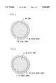
- FIG. 1 is a sectional view showing a first embodiment of the present invention with a nickel conductor core and two oxide layers;
- FIG. 2 is a sectional view showing a second embodiment of the present invention with a nickel alloy core conductor and two oxide layers;
- FIG. 3 is a sectional view showing a third embodiment of the present invention with a nickel core conductor and three oxide layers;
- FIG. 4 is a sectional view showing a fourth embodiment of the invention with a nickel alloy core conductor and two oxide layers.
- FIG. 1 shows an Ni core conductor 1 coated with an Ni oxide layer 2 formed around the core conductor.
- An Al oxide layer 3 is formed around the Ni oxide layer 2. The formation of these oxide layers will be described in more detail below.
- FIG. 2 shows a nickel alloy conductor 11 first coated with an Ni alloy oxide layer 12 formed around the Ni alloy conductor 11.
- An Si oxide layer 13 is formed around the Ni alloy oxide layer 12.
- the nickel Ni core conductor 21 is first coated with an Ni oxide layer 22 formed around the Ni core conductor 21.
- An Si oxide layer 23 is formed around the Ni oxide layer 22.
- an Al oxide layer or Si oxide layer 24 is formed around the Si oxide layer 23.
- a nickel alloy core conductor 31 is first coated with an Ni alloy oxide layer 32 formed around the Ni alloy core conductor 31. Then, an Al-Si composite oxide layer 33 is formed around the Ni alloy oxide layer 32.
- a first oxide layer of Ni or an Ni alloy is first formed on an outer surface of a conductor of Ni or Ni alloy by oxidizing the conductor in a vapor phase containing oxygen. Then, a second oxide layer of Al and/or Si is formed on the first oxide layer.
- Ni or Ni alloy is an inactive metal which has an inferior affinity for a metal oxide of Al or Si.
- a surface of Ni or Ni alloy is directly coated with such an Al or Si oxide, a rather poor adhesion is obtained and the coating is immediately separated from the Ni or Ni alloy.
- the present invention teaches to first oxidize a core conductor of Ni or Ni alloy in a vapor phase containing oxygen so as, to form an oxide layer of Ni or Ni alloy.
- the so formed nickel oxide layer or Ni alloy oxide layer very strongly adheres to the surface of the Ni or Ni alloy. This strong bonding is due to the fact that the nickel oxide or the nickel alloy oxide has an excellent affinity for the nickel or nickel alloy.
- the nickel or nickel alloy oxide has a strong affinity to aluminum oxide or silicon oxide and hence also strongly bonds to the outer layer of Al or Si oxide and to the conductor core. According to the present invention, therefore, the oxide layer of Al and/or Si is not separated for all practical purposes from the intermediate oxide layer, whereby an excellent flexibility is obtained when the inorganic insulating coating is applied to a wire forming a core conductor, for example.
- the oxide layer of Al and/or Si is obtained by applying a solution prepared by hydrolyzing and polycondensing an alkoxide of Al and/or Si in a solvent, drying the same for allowing gelation, and thereafter heating the so-obtained gel.
- the Al and/or Si oxide layer formed in the aforementioned manner has a melting point exceeding that of the Ni or Ni alloy. Additionally, the Al and/or Si oxide layer is formed without any melting process.
- the critical temperature to which conductors or other members of the present invention with their inorganic insulating coatings may be exposed in operation is not restricted by the melting point of the oxide layer. Rather, the present insulating members can be heated to a temperature limited only by the melting point of the Ni core or the Ni alloy core.
- the oxide layer formed in the aforementioned manner has characteristics such as an extreme denseness, a smooth surface and a small adsorption of gases, e.g. steam or the like.
- the present members have an excellent insulability and a high moisture resistance.
- Preferred embodiments have been produced as two conductors C1 and C2 which were oxidized as follows.
- L1 A solution L1 was obtained by mixing tributoxy aluminum, triethanolamine, water, and isopropyl alcohol in mole ratios of 1:2:1:16. The mixture was hydrolyzed and polycondensed at 50° C. for 1 hour while stirring the mixture.
- L2 A solution L2 was obtained by adding nitric acid to a mixed solution prepared by mixing tributyl orthosilicate, water, and isopropyl alcohol in mole ratios of 2:8:15 at a rate of 3/100 moles with respect to tetrabutyl orthosilicate. The mixture was hydrolyzed and polycondensed at 80° C. for 2 hours while stirring the mixture.
- An oxidized nickel conductor C1 was coated with the coating solution L1 and heated at 500° C. for 10 minutes. The coating and heating was repeated 10 times, to form an Al oxide layer of 4 ⁇ m thickness on the first nickel oxide layer.
- An oxidized nickel alloy conductor C2 was coated with the coating solution L2 and heated at 500° C. for 10 minutes. The coating and heating was repeated 10 times, to form an Si oxide layer of 5 ⁇ m thickness on the first nickel alloy oxide layer.
- An oxidized nickel conductor C1 was coated with the coating solution L2 and heated at 500° C. for 10 minutes.
- the coating and heating was repeated 5 times to form an Si-oxide layer having a thickness of 2.5 ⁇ m. Then, a further coating operation was performed on the first formed Si-oxide layer, with the coating solution L1. The sample was again heated at 500° C. for 10 minutes. The coating and heating was repeated 5 times to form an Al oxide layer of 2 ⁇ m thickness on the first formed Si oxide layer of 2.5 ⁇ m thickness.
- An oxidized conductor C2 was coated with the coating solution L3 and heated at 500° C. for 10 minutes. The coating and heating was repeated 10 times to form an Al-Si composite oxide layer of 6 ⁇ m in thickness.
- An aluminum wire was anodized in a bath of sulfuric acid to form an Al oxide layer of 10 ⁇ m thickness on the aluminum surface.
- An oxidized conductor C2 was coated with a slip which was prepared by mixing a commercially available frit (composite oxide of Ba, Ca, Ti and Si: GSP220A552 sold by Toshiba Glass Co., Ltd.) with water.
- the wire coated with the slip was heated to 900° C. to form a homogeneous metal composite oxide layer of 100 ⁇ m thickness through a melted state.
- All the coating operations were, for example, performed by dipping the wire into the respective coating solution.
- the above Table shows the breakdown voltages and the flexibility values of the wires of Examples 1 to 4 of the invention and of the two Comparative Examples.
- the flexibility values were evaluated in terms of diameter ratios, by winding the wires on circular cylinders of a prescribed diameter D and measuring the minimum diameters causing no separation of the insulating inorganic compound coatings or layers from the conductor core.
- the diameter D was 0.5 mm.
- the inorganic insulating coating on a conductor wire according to the present invention forms an insulating inorganic compound layer which is well bonded to the conductor core and has an excellent heat resistance and insulability.
Abstract
Description
______________________________________
Test Results
Example      Breakdown Voltage
                           Flexibility
______________________________________
1             500 V        6 D
2             600 V        5 D
3             800 V        8 D
4             400 V        3 D
Comparative   300 V        50 D
Example 1
Comparative   1200 V       1000 D
Example 2
______________________________________
Claims (17)
Priority Applications (1)
| Application Number | Priority Date | Filing Date | Title |
|---|---|---|---|
| US08/093,315 US5436409A (en) | 1991-01-10 | 1993-07-16 | Electrical conductor member such as a wire with an inorganic insulating coating |
Applications Claiming Priority (4)
| Application Number | Priority Date | Filing Date | Title |
|---|---|---|---|
| JP3-1645 | 1991-01-10 | ||
| JP3001645A JPH04242011A (en) | 1991-01-10 | 1991-01-10 | Inorganic insulative member |
| US81146091A | 1991-12-19 | 1991-12-19 | |
| US08/093,315 US5436409A (en) | 1991-01-10 | 1993-07-16 | Electrical conductor member such as a wire with an inorganic insulating coating |
Related Parent Applications (1)
| Application Number | Title | Priority Date | Filing Date |
|---|---|---|---|
| US81146091A Continuation-In-Part | 1991-01-10 | 1991-12-19 |
Publications (1)
| Publication Number | Publication Date |
|---|---|
| US5436409A true US5436409A (en) | 1995-07-25 |
Family
ID=26334913
Family Applications (1)
| Application Number | Title | Priority Date | Filing Date |
|---|---|---|---|
| US08/093,315 Expired - Fee Related US5436409A (en) | 1991-01-10 | 1993-07-16 | Electrical conductor member such as a wire with an inorganic insulating coating |
Country Status (1)
| Country | Link |
|---|---|
| US (1) | US5436409A (en) |
Cited By (28)
| Publication number | Priority date | Publication date | Assignee | Title |
|---|---|---|---|---|
| US20040118583A1 (en) * | 2002-12-20 | 2004-06-24 | Tonucci Ronald J. | High voltage, high temperature wire |
| US7002072B2 (en) * | 2002-12-20 | 2006-02-21 | The United States Of America As Represented By The Secretary Of The Navy | High voltage, high temperature wire |
| US20070075816A1 (en) * | 2005-10-05 | 2007-04-05 | Lotfi Ashraf W | Power module with a magnetic device having a conductive clip |
| US20070075817A1 (en) * | 2005-10-05 | 2007-04-05 | Lotfi Ashraf W | Magnetic device having a conductive clip |
| US20070074386A1 (en) * | 2005-10-05 | 2007-04-05 | Lotfi Ashraf W | Method of forming a power module with a magnetic device having a conductive clip |
| US20090066467A1 (en) * | 2007-09-10 | 2009-03-12 | Lotfi Ashraf W | Micromagnetic Device and Method of Forming the Same |
| US20090068761A1 (en) * | 2007-09-10 | 2009-03-12 | Lotfi Ashraf W | Method of Forming a Micromagnetic Device |
| US20090066468A1 (en) * | 2007-09-10 | 2009-03-12 | Lotfi Ashraf W | Power Converter Employing a Micromagnetic Device |
| US20090068347A1 (en) * | 2007-09-10 | 2009-03-12 | Lotfi Ashraf W | Method of Forming a Micromagnetic Device |
| US20090068400A1 (en) * | 2007-09-10 | 2009-03-12 | Lotfi Ashraf W | Micromagnetic Device and Method of Forming the Same |
| US20090200061A1 (en) * | 2008-02-12 | 2009-08-13 | The Government Of The United States Of America, As Represented By The Secretary Of The Navy | High temperature high voltage cable |
| US20100087036A1 (en) * | 2008-10-02 | 2010-04-08 | Lotfi Ashraf W | Module having a stacked passive element and method of forming the same |
| US20110101949A1 (en) * | 2008-04-16 | 2011-05-05 | Douglas Dean Lopata | Power Converter with Controller Operable in Selected Modes of Operation |
| US20110101948A1 (en) * | 2008-04-16 | 2011-05-05 | Douglas Dean Lopata | Power Converter with Controller Operable in Selected Modes of Operation |
| US8043544B2 (en) | 2004-11-10 | 2011-10-25 | Enpirion, Inc. | Method of manufacturing an encapsulated package for a magnetic device |
| US8266793B2 (en) | 2008-10-02 | 2012-09-18 | Enpirion, Inc. | Module having a stacked magnetic device and semiconductor device and method of forming the same |
| US8339802B2 (en) | 2008-10-02 | 2012-12-25 | Enpirion, Inc. | Module having a stacked magnetic device and semiconductor device and method of forming the same |
| US8528190B2 (en) | 2004-11-10 | 2013-09-10 | Enpirion, Inc. | Method of manufacturing a power module |
| US8541991B2 (en) | 2008-04-16 | 2013-09-24 | Enpirion, Inc. | Power converter with controller operable in selected modes of operation |
| US8631560B2 (en) | 2005-10-05 | 2014-01-21 | Enpirion, Inc. | Method of forming a magnetic device having a conductive clip |
| US8692532B2 (en) | 2008-04-16 | 2014-04-08 | Enpirion, Inc. | Power converter with controller operable in selected modes of operation |
| US8698463B2 (en) | 2008-12-29 | 2014-04-15 | Enpirion, Inc. | Power converter with a dynamically configurable controller based on a power conversion mode |
| US8867295B2 (en) | 2010-12-17 | 2014-10-21 | Enpirion, Inc. | Power converter for a memory module |
| US9054086B2 (en) | 2008-10-02 | 2015-06-09 | Enpirion, Inc. | Module having a stacked passive element and method of forming the same |
| US9509217B2 (en) | 2015-04-20 | 2016-11-29 | Altera Corporation | Asymmetric power flow controller for a power converter and method of operating the same |
| US9548714B2 (en) | 2008-12-29 | 2017-01-17 | Altera Corporation | Power converter with a dynamically configurable controller and output filter |
| US20180137950A1 (en) * | 2016-04-29 | 2018-05-17 | Shenzhen Sunlord Electronics Co., Ltd. | Composite wire, method for preparing same, and method for preparing power inductor |
| WO2021041200A1 (en) * | 2019-08-23 | 2021-03-04 | Zeus Industrial Products, Inc. | Polymer-coated wires |
Citations (6)
| Publication number | Priority date | Publication date | Assignee | Title |
|---|---|---|---|---|
| US2010145A (en) * | 1932-12-09 | 1935-08-06 | Heints & Kaufman Ltd | Metal-to-glass seal |
| US2975078A (en) * | 1957-10-21 | 1961-03-14 | Cons Electrodynamics Corp | Ceramic coated wire |
| EP0012422A1 (en) * | 1978-12-12 | 1980-06-25 | The Fujikura Cable Works, Ltd. | Heat-resistant electrically insulated wires and a method for preparing the same |
| EP0292780A1 (en) * | 1987-05-12 | 1988-11-30 | Sumitomo Electric Industries, Ltd. | Electric wire |
| GB2220295A (en) * | 1988-06-29 | 1990-01-04 | Westinghouse Electric Corp | Superconducting articles |
| JPH02301909A (en) * | 1989-05-16 | 1990-12-14 | Sumitomo Electric Ind Ltd | Inorganic insulated cable and its manufacture |
-
1993
- 1993-07-16 US US08/093,315 patent/US5436409A/en not_active Expired - Fee Related
Patent Citations (6)
| Publication number | Priority date | Publication date | Assignee | Title |
|---|---|---|---|---|
| US2010145A (en) * | 1932-12-09 | 1935-08-06 | Heints & Kaufman Ltd | Metal-to-glass seal |
| US2975078A (en) * | 1957-10-21 | 1961-03-14 | Cons Electrodynamics Corp | Ceramic coated wire |
| EP0012422A1 (en) * | 1978-12-12 | 1980-06-25 | The Fujikura Cable Works, Ltd. | Heat-resistant electrically insulated wires and a method for preparing the same |
| EP0292780A1 (en) * | 1987-05-12 | 1988-11-30 | Sumitomo Electric Industries, Ltd. | Electric wire |
| GB2220295A (en) * | 1988-06-29 | 1990-01-04 | Westinghouse Electric Corp | Superconducting articles |
| JPH02301909A (en) * | 1989-05-16 | 1990-12-14 | Sumitomo Electric Ind Ltd | Inorganic insulated cable and its manufacture |
Cited By (49)
| Publication number | Priority date | Publication date | Assignee | Title |
|---|---|---|---|---|
| US20040118583A1 (en) * | 2002-12-20 | 2004-06-24 | Tonucci Ronald J. | High voltage, high temperature wire |
| US7002072B2 (en) * | 2002-12-20 | 2006-02-21 | The United States Of America As Represented By The Secretary Of The Navy | High voltage, high temperature wire |
| US8528190B2 (en) | 2004-11-10 | 2013-09-10 | Enpirion, Inc. | Method of manufacturing a power module |
| US8043544B2 (en) | 2004-11-10 | 2011-10-25 | Enpirion, Inc. | Method of manufacturing an encapsulated package for a magnetic device |
| US20070075817A1 (en) * | 2005-10-05 | 2007-04-05 | Lotfi Ashraf W | Magnetic device having a conductive clip |
| US20070074386A1 (en) * | 2005-10-05 | 2007-04-05 | Lotfi Ashraf W | Method of forming a power module with a magnetic device having a conductive clip |
| US8631560B2 (en) | 2005-10-05 | 2014-01-21 | Enpirion, Inc. | Method of forming a magnetic device having a conductive clip |
| US10304615B2 (en) | 2005-10-05 | 2019-05-28 | Enpirion, Inc. | Method of forming a power module with a magnetic device having a conductive clip |
| US8384506B2 (en) | 2005-10-05 | 2013-02-26 | Enpirion, Inc. | Magnetic device having a conductive clip |
| US8701272B2 (en) | 2005-10-05 | 2014-04-22 | Enpirion, Inc. | Method of forming a power module with a magnetic device having a conductive clip |
| US20070075816A1 (en) * | 2005-10-05 | 2007-04-05 | Lotfi Ashraf W | Power module with a magnetic device having a conductive clip |
| US8139362B2 (en) | 2005-10-05 | 2012-03-20 | Enpirion, Inc. | Power module with a magnetic device having a conductive clip |
| US7688172B2 (en) | 2005-10-05 | 2010-03-30 | Enpirion, Inc. | Magnetic device having a conductive clip |
| US20090068347A1 (en) * | 2007-09-10 | 2009-03-12 | Lotfi Ashraf W | Method of Forming a Micromagnetic Device |
| US9299489B2 (en) | 2007-09-10 | 2016-03-29 | Enpirion, Inc. | Micromagnetic device and method of forming the same |
| US20090066467A1 (en) * | 2007-09-10 | 2009-03-12 | Lotfi Ashraf W | Micromagnetic Device and Method of Forming the Same |
| US8618900B2 (en) | 2007-09-10 | 2013-12-31 | Enpirion, Inc. | Micromagnetic device and method of forming the same |
| US7955868B2 (en) * | 2007-09-10 | 2011-06-07 | Enpirion, Inc. | Method of forming a micromagnetic device |
| US8018315B2 (en) | 2007-09-10 | 2011-09-13 | Enpirion, Inc. | Power converter employing a micromagnetic device |
| US20090068761A1 (en) * | 2007-09-10 | 2009-03-12 | Lotfi Ashraf W | Method of Forming a Micromagnetic Device |
| US8133529B2 (en) | 2007-09-10 | 2012-03-13 | Enpirion, Inc. | Method of forming a micromagnetic device |
| US20090066468A1 (en) * | 2007-09-10 | 2009-03-12 | Lotfi Ashraf W | Power Converter Employing a Micromagnetic Device |
| US7920042B2 (en) | 2007-09-10 | 2011-04-05 | Enpirion, Inc. | Micromagnetic device and method of forming the same |
| US8339232B2 (en) | 2007-09-10 | 2012-12-25 | Enpirion, Inc. | Micromagnetic device and method of forming the same |
| US20090068400A1 (en) * | 2007-09-10 | 2009-03-12 | Lotfi Ashraf W | Micromagnetic Device and Method of Forming the Same |
| US20090200061A1 (en) * | 2008-02-12 | 2009-08-13 | The Government Of The United States Of America, As Represented By The Secretary Of The Navy | High temperature high voltage cable |
| US7692093B2 (en) * | 2008-02-12 | 2010-04-06 | The United States Of America As Represented By The Secretary Of The Navy | High temperature high voltage cable |
| US9246390B2 (en) | 2008-04-16 | 2016-01-26 | Enpirion, Inc. | Power converter with controller operable in selected modes of operation |
| US8541991B2 (en) | 2008-04-16 | 2013-09-24 | Enpirion, Inc. | Power converter with controller operable in selected modes of operation |
| US20110101948A1 (en) * | 2008-04-16 | 2011-05-05 | Douglas Dean Lopata | Power Converter with Controller Operable in Selected Modes of Operation |
| US20110101949A1 (en) * | 2008-04-16 | 2011-05-05 | Douglas Dean Lopata | Power Converter with Controller Operable in Selected Modes of Operation |
| US8686698B2 (en) | 2008-04-16 | 2014-04-01 | Enpirion, Inc. | Power converter with controller operable in selected modes of operation |
| US8692532B2 (en) | 2008-04-16 | 2014-04-08 | Enpirion, Inc. | Power converter with controller operable in selected modes of operation |
| US8339802B2 (en) | 2008-10-02 | 2012-12-25 | Enpirion, Inc. | Module having a stacked magnetic device and semiconductor device and method of forming the same |
| US8153473B2 (en) | 2008-10-02 | 2012-04-10 | Empirion, Inc. | Module having a stacked passive element and method of forming the same |
| US20100087036A1 (en) * | 2008-10-02 | 2010-04-08 | Lotfi Ashraf W | Module having a stacked passive element and method of forming the same |
| US9054086B2 (en) | 2008-10-02 | 2015-06-09 | Enpirion, Inc. | Module having a stacked passive element and method of forming the same |
| US8266793B2 (en) | 2008-10-02 | 2012-09-18 | Enpirion, Inc. | Module having a stacked magnetic device and semiconductor device and method of forming the same |
| US9548714B2 (en) | 2008-12-29 | 2017-01-17 | Altera Corporation | Power converter with a dynamically configurable controller and output filter |
| US8698463B2 (en) | 2008-12-29 | 2014-04-15 | Enpirion, Inc. | Power converter with a dynamically configurable controller based on a power conversion mode |
| US9627028B2 (en) | 2010-12-17 | 2017-04-18 | Enpirion, Inc. | Power converter for a memory module |
| US8867295B2 (en) | 2010-12-17 | 2014-10-21 | Enpirion, Inc. | Power converter for a memory module |
| US9509217B2 (en) | 2015-04-20 | 2016-11-29 | Altera Corporation | Asymmetric power flow controller for a power converter and method of operating the same |
| US10084380B2 (en) | 2015-04-20 | 2018-09-25 | Altera Corporation | Asymmetric power flow controller for a power converter and method of operating the same |
| US20180137950A1 (en) * | 2016-04-29 | 2018-05-17 | Shenzhen Sunlord Electronics Co., Ltd. | Composite wire, method for preparing same, and method for preparing power inductor |
| US10867748B2 (en) * | 2016-04-29 | 2020-12-15 | Shenzhen Sunlord Electronics Co., Ltd. | Method for preparing a composite wire and a power inductor |
| WO2021041200A1 (en) * | 2019-08-23 | 2021-03-04 | Zeus Industrial Products, Inc. | Polymer-coated wires |
| US10991481B2 (en) | 2019-08-23 | 2021-04-27 | Zeus Industrial Products, Inc. | Polymer-coated wires |
| US11631504B2 (en) | 2019-08-23 | 2023-04-18 | Zeus Company Inc. | Polymer-coated wires |
Similar Documents
| Publication | Publication Date | Title |
|---|---|---|
| US5436409A (en) | Electrical conductor member such as a wire with an inorganic insulating coating | |
| EP0410003B1 (en) | Insulated electric wire | |
| US4429007A (en) | Electrical wire insulation and electromagnetic coil | |
| CA2058147C (en) | Electrical insulated wire | |
| CA1295890C (en) | Electrical wire with refractory coating | |
| EP0729157B1 (en) | Electrical conductor member such as a wire with an inorganic insulating coating | |
| CA2142765C (en) | Inorganic insulating member | |
| EP0494424B1 (en) | Method for the production of an electrical conductor having an inorganic insulation | |
| EP0460238B1 (en) | Insulated wire | |
| JPH0125166B2 (en) | ||
| JPH08264028A (en) | Insulation-coated electric conductor and manufacture thereof | |
| JPH02301909A (en) | Inorganic insulated cable and its manufacture | |
| JPH06187845A (en) | Heat-resistant insulated wire | |
| JPS639326B2 (en) | ||
| JPH03105803A (en) | Inorganic insulation wire and its manufacture | |
| JP2709592B2 (en) | Heat-resistant insulated wire | |
| JPH04303517A (en) | Insulated wire | |
| JP3336735B2 (en) | Insulated wire | |
| JP2943196B2 (en) | Heat-resistant insulated wire | |
| JPH02270217A (en) | Insulated wire | |
| JPS6362041B2 (en) | ||
| JPS6336085B2 (en) | ||
| KR940001884B1 (en) | Insulated electric wire | |
| SU156198A1 (en) | ||
| JP3074741B2 (en) | Insulated wire |
Legal Events
| Date | Code | Title | Description |
|---|---|---|---|
| AS | Assignment |
Owner name: SUMITOMO ELECTRIC INDUSTRIES, LTD., JAPAN Free format text: ASSIGNMENT OF ASSIGNORS INTEREST;ASSIGNORS:SAWADA, KAZUO;INAZAWA, SHINJI;YAMADA, KOUICHI;REEL/FRAME:007274/0281 Effective date: 19930706 |
|
| CC | Certificate of correction | ||
| FEPP | Fee payment procedure |
Free format text: PAYOR NUMBER ASSIGNED (ORIGINAL EVENT CODE: ASPN); ENTITY STATUS OF PATENT OWNER: LARGE ENTITY |
|
| FPAY | Fee payment |
Year of fee payment: 4 |
|
| FPAY | Fee payment |
Year of fee payment: 8 |
|
| REMI | Maintenance fee reminder mailed | ||
| LAPS | Lapse for failure to pay maintenance fees | ||
| STCH | Information on status: patent discontinuation |
Free format text: PATENT EXPIRED DUE TO NONPAYMENT OF MAINTENANCE FEES UNDER 37 CFR 1.362 |
|
| FP | Lapsed due to failure to pay maintenance fee |
Effective date: 20070725 |