US5430373A - Absolute encoder - Google Patents
Absolute encoder Download PDFInfo
- Publication number
- US5430373A US5430373A US08/009,267 US926793A US5430373A US 5430373 A US5430373 A US 5430373A US 926793 A US926793 A US 926793A US 5430373 A US5430373 A US 5430373A
- Authority
- US
- United States
- Prior art keywords
- tracks
- track
- absolute
- patterns
- circuits
- Prior art date
- Legal status (The legal status is an assumption and is not a legal conclusion. Google has not performed a legal analysis and makes no representation as to the accuracy of the status listed.)
- Expired - Fee Related
Links
- 230000002093 peripheral effect Effects 0.000 description 5
- 230000004907 flux Effects 0.000 description 3
- 238000000034 method Methods 0.000 description 2
- 238000004904 shortening Methods 0.000 description 2
- 238000010276 construction Methods 0.000 description 1
- 230000007423 decrease Effects 0.000 description 1
- 230000003247 decreasing effect Effects 0.000 description 1
- 238000001514 detection method Methods 0.000 description 1
- 238000010586 diagram Methods 0.000 description 1
- 230000000694 effects Effects 0.000 description 1
- 230000002708 enhancing effect Effects 0.000 description 1
- 238000002474 experimental method Methods 0.000 description 1
- 238000012986 modification Methods 0.000 description 1
- 230000004048 modification Effects 0.000 description 1
- 238000005070 sampling Methods 0.000 description 1
- 230000035945 sensitivity Effects 0.000 description 1
Images


Classifications
-
- G—PHYSICS
- G01—MEASURING; TESTING
- G01D—MEASURING NOT SPECIALLY ADAPTED FOR A SPECIFIC VARIABLE; ARRANGEMENTS FOR MEASURING TWO OR MORE VARIABLES NOT COVERED IN A SINGLE OTHER SUBCLASS; TARIFF METERING APPARATUS; MEASURING OR TESTING NOT OTHERWISE PROVIDED FOR
- G01D5/00—Mechanical means for transferring the output of a sensing member; Means for converting the output of a sensing member to another variable where the form or nature of the sensing member does not constrain the means for converting; Transducers not specially adapted for a specific variable
- G01D5/12—Mechanical means for transferring the output of a sensing member; Means for converting the output of a sensing member to another variable where the form or nature of the sensing member does not constrain the means for converting; Transducers not specially adapted for a specific variable using electric or magnetic means
- G01D5/14—Mechanical means for transferring the output of a sensing member; Means for converting the output of a sensing member to another variable where the form or nature of the sensing member does not constrain the means for converting; Transducers not specially adapted for a specific variable using electric or magnetic means influencing the magnitude of a current or voltage
- G01D5/142—Mechanical means for transferring the output of a sensing member; Means for converting the output of a sensing member to another variable where the form or nature of the sensing member does not constrain the means for converting; Transducers not specially adapted for a specific variable using electric or magnetic means influencing the magnitude of a current or voltage using Hall-effect devices
- G01D5/145—Mechanical means for transferring the output of a sensing member; Means for converting the output of a sensing member to another variable where the form or nature of the sensing member does not constrain the means for converting; Transducers not specially adapted for a specific variable using electric or magnetic means influencing the magnitude of a current or voltage using Hall-effect devices influenced by the relative movement between the Hall device and magnetic fields
-
- G—PHYSICS
- G01—MEASURING; TESTING
- G01D—MEASURING NOT SPECIALLY ADAPTED FOR A SPECIFIC VARIABLE; ARRANGEMENTS FOR MEASURING TWO OR MORE VARIABLES NOT COVERED IN A SINGLE OTHER SUBCLASS; TARIFF METERING APPARATUS; MEASURING OR TESTING NOT OTHERWISE PROVIDED FOR
- G01D5/00—Mechanical means for transferring the output of a sensing member; Means for converting the output of a sensing member to another variable where the form or nature of the sensing member does not constrain the means for converting; Transducers not specially adapted for a specific variable
- G01D5/12—Mechanical means for transferring the output of a sensing member; Means for converting the output of a sensing member to another variable where the form or nature of the sensing member does not constrain the means for converting; Transducers not specially adapted for a specific variable using electric or magnetic means
- G01D5/244—Mechanical means for transferring the output of a sensing member; Means for converting the output of a sensing member to another variable where the form or nature of the sensing member does not constrain the means for converting; Transducers not specially adapted for a specific variable using electric or magnetic means influencing characteristics of pulses or pulse trains; generating pulses or pulse trains
- G01D5/249—Mechanical means for transferring the output of a sensing member; Means for converting the output of a sensing member to another variable where the form or nature of the sensing member does not constrain the means for converting; Transducers not specially adapted for a specific variable using electric or magnetic means influencing characteristics of pulses or pulse trains; generating pulses or pulse trains using pulse code
- G01D5/2497—Absolute encoders
Definitions
- the present invention relates to an encoder, and more particularly relates to an absolute encoder wherein an output of a rotary member is coded, so that an absolute position of the rotary member can be detected directly.
- a magnetic type absolute encoder is formed by combining a detector utilizing magneto-resistive elements (which will hereinafter be referred as MR elements) with a magnetic drum on which magnetic patterns of more than two rows are recorded magnetically as described in Japanese Patents Laid-Open Nos. 54-118259 and 62-83619.
- MR elements magneto-resistive elements
- n tracks are necessary in order to obtain a resolution of 2 n in such absolute encoder.
- a plurality of tracks 30 are disposed on an outer peripheral surface of a magnetic drum 10, informations of three bits are recorded on said tracks 30, and a magnetic sensor 20 having MR elements (R 01 , R 02 - - - ) of a number corresponding to said three bits facing the magnetic drum 10, so that an absolute value can be outputted by combining signals from the plural MR elements.
- Japanese Patent Laid-Open No. 2-24518 discloses an absolute encoder wherein absolute signals can be obtained from tracks having absolute patterns.
- leakage magnetic fluxes of N, S shown by arrows on the magnetic drum are sensed by the MR elements to generate signals in the absolute encoder. Accordingly, if the recording pitch is increased, the width of the magnetic sensor 20 becomes large as shown in FIG. 25. Accordingly, as shown in FIG. 25, a distance ⁇ between an MR element at an end portion of the magnetic sensor 20 and the center of the magnetic drum 10 becomes larger than a distance d between an MR element at the center portion of the sensor 20 and the center of the magnetic drum 10.
- an absolute encoder comprising a magnetic drum having first, second, and third tracks; and a pattern detector for reading patterns on the first, second and third tracks; wherein absolute patterns of circulatory random sequence codes are divided and recorded on the first and second tracks which are arranged side-by-side on the magnetic drum in the axial direction thereof, wherein the third track is provided for generating sinewaves of two phases in synchronism with the reading of the absolute patterns on the first and second tracks, and wherein an output is obtained by combining a first value of an absolute position detected by the pattern detector from the first and second tracks with a second value of an absolute position obtained by operating information of the sinewaves from the third track.
- the absolute encoder of the present invention further comprises a first signal and a second signal; wherein the first and second signal are deviated in phase from each other by one half of pole pitch of magnetic recording and are obtained from the first and second tracks by the pattern detector; wherein one of the first and second signals is selected according to the second value of the absolute position obtained by operating the sinewave information; and wherein the output is obtained by interpolating the second value of the absolute position obtained by operating the sinewave information to the: selected signal.
- an absolute encoder comprising a magnetic drum having first, second and third tracks; and a pattern detector for reading patterns on the first, second and third tracks; wherein absolute patterns of circulatory random sequence codes are divided and recorded on the first and second tracks which are arranged side-by-side on respective first and second track sides of the magnetic drum in the axial direction thereof, wherein the third track is provided for generating sinewaves of two phases in synchronism with the reading of the absolute patterns on the first and second tracks, wherein the pattern detector has a plurality of sets of magneto-resistive elements which are deviated in position from each other by one half of the recording pitch of the first, second and third tracks, wherein each of the plurality of sets has two magneto-resistive elements facing the first and second tracks respectively and connected with each other to form a plurality of circuits each having two magneto-resistive elements, wherein each of said plurality of circuits has a first track side and a second track side corresponding to the
- an absolute encoder comprising a magnetic drum having first, second, and third tracks; and a pattern detector for reading patterns on the first, second and third tracks; wherein absolute patterns of circulatory random sequence codes are divided and recorded on the first and second tracks which are arranged side-by-side on respective first and second track sides of the magnetic drum in the axial direction thereof, wherein the third track is provided for generating sinewaves of two phases in synchronism with the reading of the absolute patterns on the first and second tracks, wherein the pattern detector has a plurality of sets of magneto-resistive elements which are deviated in position from each other by one half of the recording pitch of the first, second and third tracks, wherein each of the plurality of sets has two magneto-resistive elements facing the first and second tracks respectively and connected with each other to form a plurality of circuits each having two magneto-resistive elements, wherein each of said plurality of circuits has a first track side and a second track side corresponding to
- an absolute encoder comprising a magnetic drum having first, second and third tracks; and a pattern detector for reading patterns on the first, second and third tracks; wherein absolute patterns of circulatory random sequence codes are divided and recorded on the first and second tracks which are arranged side-by-side on respective first and second track sides of the magnetic drum in the axial direction thereof, wherein the third track is provided for generating sinewaves of two phases in synchronism with the reading of the absolute patterns on the first and second tracks, wherein the pattern detector has a first to (n+1)th sets of magneto-resistive elements which are deviated in position from each other by one half of the recording pitch of the first, second and third tracks, where n is a whole number greater than three, wherein each of the plurality of sets has two magneto-resistive elements facing the first and second tracks respectively and connected with each other to form a plurality of circuits each having two magneto-resistive elements, wherein each of said plurality of circuits
- FIG. 1 is a perspective view showing an embodiment of an absolute encoder according to the present invention
- FIG. 2 is an extended view of an outer peripheral surface of a magnetic drum in the absolute encoder according to the present invention
- FIG. 3 is an extended view showing MR elements of a magnetic sensor in the absolute encoder according to the present invention.
- FIG. 4 is a view showing wave forms of signals from the magnetic sensor and processing circuits in the absolute encoder according to the present invention.
- FIG. 5 shows a first processing circuit in the absolute encoder according to the present invention
- FIG. 6 shows a second processing circuit in the absolute encoder according to the present invention
- FIG. 7 is a view showing a pattern to be detected and a detector in the absolute encoder according to the present invention.
- FIG. 8 is a view explaining a detected pattern in the absolute encoder according to the present invention.
- FIG. 9 is a block diagram of an operating and processing device in the absolute encoder according to the present invention.
- FIG. 10 is a view explaining sinewaves divided into eight regions in the absolute encoder according to the present invention.
- FIG. 11 is a view explaining the sum of a coarse signal and a dense signal in the absolute encoder according to the present invention.
- FIG. 12 is an extended view showing magnetic tracks and MR elements of a magnetic sensor in another embodiment of the present invention.
- FIG. 13 is a third processing circuit in said embodiment of the absolute encoder according to the present invention.
- FIG. 14 is a view showing a magnetic track, a first signal, a second signal and sinewaves in said embodiment of the absolute encoder according to the present invention.
- FIG. 15 is a perspective view showing an absolute encoder in a further embodiment according to the present invention.
- FIG. 16 is an extended view of an outer peripheral surface of a magnetic drum in the absolute encoder of said embodiment according to the present invention.
- FIG. 17 is an extended view showing magnetic tracks and MR elements of a magnetic sensor in said embodiment according to the present invention.
- FIG. 18 is a view explaining the relation between the magnetic drum and a magnetic sensor in the said embodiment according to the present invention.
- FIG. 19 is a view showing a pattern to be detected and bits in said embodiment according to the present invention.
- FIG. 20 is a view showing detected patterns in said embodiment according to the present invention.
- FIG. 21 is an extended view showing magnetic tracks and MR elements of a magnetic sensor in a yet further embodiment of an absolute encoder according to the present invention.
- FIG. 22 is an extended view showing magnetic tracks and MR elements of a magnetic sensor in the other embodiment of an absolute encoder according to the present invention.
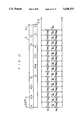
- FIG. 23 is an extended view showing magnetic tracks and MR elements of a magnetic sensor in the conventional absolute encoder.
- FIG. 24 is a view explaining leakage magnetic fluxes of the magnetic drum in the conventional absolute encoder.
- FIG. 25 is a view explaining the relation between the magnetic drum and the magnetic sensor in the conventional absolute encoder.
- reference numeral 1 denotes a magnetic drum
- 2 denotes a magnetic sensor having MR elements thereon
- 3 denotes a magnetic track formed on an outer peripheral surface of the magnetic drum 1 in a circumferential direction thereof.
- the magnetic track 3 in the present invention comprises three magnetic tracks 3-1, 3-2 and 3-3 arrange side-by-side on the magnetic drum 1 in the axial direction thereof, respectively.
- Two upper side tracks 3-1 and 3-2 are used as a track for outputting absolute positions.
- the magnetic track 3-1 has no signal recorded portions
- the magnetic track 3-2 has signal recorded portions corresponding in position to said no signal recorded portions on the magnetic track 3-1, and has no signal recorded portions corresponding in position to said signal recorded portions on the magnetic track 3-1.
- MR elements R 11 and R 21 are arranged corresponding to the magnetic track 3-1 and separated from each other by one half of a minimum recording pitch ⁇ on the recording track 3-1.
- MR elements R 12 and R 22 are arranged corresponding to the magnetic track 3-2, and separated from each other by one half of the minimum recording pitch ⁇ on the recording track 3-2.
- the MR elements R 11 and R 12 are connected to each other to form a circuit having three terminals.
- the MR elements R 21 and R 22 are connected to each other to form a circuit having a three-terminal.
- outputs e 1 and e 2 as shown in FIG. 4 are generated from said two circuits, respectively.
- An output e 01 can be obtained by operating the outputs e 1 and e 2 in a first processing circuit shown in FIG. 5.
- reference numeral 4a denotes an operational amplifier and reference symbols Ri and Rf are fixed resistances, respectively.
- a set of "H bridge” comprising four MR elements R 11 , R 12 , and R 21 and R 22 forms a detector of one bit. An output of absolute positions of n bits can be obtained, if n sets of the "H bridge" are arranged at an interval of the minimum recording pitch ⁇ on the magnetic track.
- a minimum of recording pitch of the magnetic track 3-3 for generating sinewave signals of two phases is set to ⁇ as like as that of the magnetic tracks 3-1 and 3-2.
- MR elements R 41 and R 42 are arranged corresponding to the magnetic track 3-3 and separated from each other by ⁇ /2 on the magnetic track 3-3 as shown in FIG. 3.
- the MR elements R 31 and R 32 are connected to each other to form a circuit having a three-terminal generating an output e 3 and the MR elements R 41 and R 42 are connected to each other to form a circuit having a three-terminal generating an output e 4 , as shown in FIGS. 3 and 6.
- An output e 02 having sinewaves of two phases, or of sin ⁇ and cos ⁇ which are separated from each other in phase by ⁇ /4, as shown in FIG. 4 can be obtained from a second processing circuit shown in FIG. 6 using the outputs e 3 and e 4 .
- reference numeral 4b denotes an operational amplifier.
- the two circuits each having the three-terminal and forming "H bridge" are separated from each other by n ⁇ /3, so that the output e 02 obtained by operating in the operational amplifier 4b shown in FIG. 6 becomes sinewaves having no the third harmonic and having less distortion.
- FIG. 7 showing a pattern 5 to be detected and a detector 6.
- the absolute positions of eight portions can be detected as codes of 0 to 7 by detecting signals of three bits from the pattern 5 to be detected by the detector 6.
- the three bit signals are read by the detector 6 while shifting the detector 6 bit by bit in the rightward direction the bit signals can be coded to, as shown in FIG. 8,
- the eight positions of the rotary member can be detected as the codes of 0 to 7. If numerical values corresponding to the coded absolute positions of the 7, 6, 4, 0, 1, 2, 5, 3 are recorded preliminarily in memory elements, the codes can be read from 0 to 7, in order.
- reference numeral 100 denotes a detector in the absolute encoder
- 101 denotes a code converter
- 102 denotes a latch circuit
- 103 denotes a wave form processing circuit such as a sampling and holding circuit
- 104 denotes a CPU
- 105 denotes an A/D converter
- 106 denotes a ROM
- 107 denotes a buffer.
- an output indicating direct absolute positions obtained from the magnetic tracks 3-1 and 3-2 among the outputs of the detector 100 of the absolute encoder is applied as a coarse data to the CPU 104 through the code converter 101 and the latch circuit 102, as well as an output of sinewaves of two phases obtained from the magnetic track is processed in the wave form processing circuit 103 and applied to the CPU 104 through the A/D converter 105.
- the output of sinewaves is referenced in the CPU 104 to a data stored in the ROM 106 and converted into a fine data which is combined with the output indicating the direct absolute positions and outputted from the buffer 107.
- one cycle of the sinewave is divided into eight regions (1) to (8), so that if absolute values of sin ⁇ and cos ⁇ are considered the regions (1) and (2) are symmetric with each other centering about b 45°.
- the regions (3) and (4), (5) and (6), and (7) and (8) are symmetric, respectively. Accordingly, if the position of the region within 0° to 360° can be determined the absolute positions can be obtained by calculating only the data within 0° to 45° . According to the manner, the processing time of the software can be reduced.
- the absolute positions of the sinewave in one cycle obtained by the operation in the CPU 104 in the operating and processing device can be expressed by a formula
- This formula indicates that no detection error is generated if the sinewaves of sin ⁇ and cos ⁇ are varied synchronously with each other.
- signals from a coarse signal portion 7 and a fine signal portion 8 are combined. Specifically, a coarse value of absolute positions obtained from the tracks having the absolute pattern is added as a high rank value to a fine value of absolute positions obtained from one cycle of the sinewave as a low rank value, so that an absolute encoder small in size and high in resolution can be realized.
- magnetic patterns on the magnetic tracks 3-1 and 3-2 are detected by the MR elements R 11 , R 12 , R 21 , and R 22 .
- the signal recording positions on the magnetic tracks 3-1 and 3-2 have a complemental relation with each other, that is, no signal recorded portions on one of the magnetic tracks 3-1 and 3-2 correspond to signal recorded portions on the other of the magnetic tracks 3-1 and 3-2. Accordingly, the output of the MR element generated at the borderline between the signal recorded portion and no signal recorded portion becomes instable.
- the output may have an error, when the coarse value of the absolute positions is obtained directly from the MR elements directly after the power switch is turned ON.
- MR elements R 11 and R 12 , R 21 and R 22 , R 31 and R 32 , and R 41 , and R 42 , - - - R.sub.(n+1)1 and R.sub.(n+1)2 for detecting magnetic records on the magnetic tracks 3-1 and 3-2 are provided and connected to form circuits each having a three-terminal, and separated from the another by ⁇ /2 to generate outputs e 1 , e 2 , e 3 - - -and e 2 .sbsb.n+1, respectively, as shown in FIG. 12.
- the outputs e 1 and e 2 are applied to input terminals of an operational amplifier 4c of a third processing circuit, and the outputs e 2 and e 4 are applied to input terminals of an operational amplifier 4d of a fourth processing circuit, as shown in FIG. 13.
- the outputs e 2 .sbsb.n-1, and e n , and e 2 .sbsb.n and e 2 .sbsb.n+1 are applied to input terminal of corresponding operational amplifiers, respectively.
- FIG. 14 shows magnetic tracks 3-1 and 3-2 having absolute patterns and a magnetic track 3-3 for forming outputs of sinewaves, as well as wave forms of first and second signals from an OR circuit 11a, and wave forms of cos ⁇ and sin ⁇ , respectively.
- the first signal is generated by processing the output e 1 of the circuit having the three-terminal formed by the MR elements R 11 and R 12 and the output e 2 of the circuit having the three-terminal formed by the MR element R 21 and R 22 by the operation amplifier 4c.
- the second signal is generated by processing the output e 2 of the circuit having the three-terminal formed by the MR elements R 21 and R 22 and the output e 3 of the circuit having the three-terminal formed by the MR elements R 31 and R 32 by the operation amplifier 4d.
- the amplitude of the first signal is zero at a position on the N pole of the magnetic track, increases gradually and becomes to a maximum at a position of ⁇ /2 thereon.
- the amplitude is constant during a range of ⁇ 1 , decreased from a position of 3 ⁇ /2 and becomes to zero at a position on the S pole of the magnetic track 3-1.
- the amplitude of the second signal is a maximum at the position on the N pole of the magnetic track, constant during a range of ⁇ 2 , decreases from the position of ⁇ /2, becomes to zero at a position ⁇ , increases to a maximum at the position of 3 ⁇ /2 and maintained to a position of 2 ⁇ .
- an output terminal of the operation amplifier 4c is connected to one of input terminals of an AND circuit 10a, as well as an output terminal of the operation amplifier 4d is connected to one of input terminals of an AND circuit 10b.
- An output of sin ⁇ in the output of sinewaves is applied to the other of input terminals of the AND circuit 10a, and an output of cos ⁇ is applied to the other of input terminals of the AND circuit 10b.
- Output terminals of the AND circuits 10a and 10b are applied two input terminals of an 0R circuit 11a to obtain a signal of absolute positions from an output of the OR circuit 11a by using an output of the operational amplifier 4c during the range of ⁇ 1 and an output of the operational amplifier 4d during the range of ⁇ 2 .
- the first signal is obtained during the range ⁇ 1 of form ⁇ /2 to 3 ⁇ /2
- the second signal is obtained during the range 02 of from 0 to ⁇ /2 with respect to the magnetic track 3-1, so that the signal of the absolute positions can be obtained at any positions on the magnetic track.
- the output signal of the OR circuit 11a shown in FIG. 13 is applied to the CPU 104 shown in FIG. 9 to combine with the sinewave signal, similar to the first embodiment.
- signals of absolute positions of n bits can be obtained by forming n sets of "H bridge" consisting of two sets of circuits each having a three-terminal, applying each output signal to each of the operational amplifiers in FIG. 13, and selecting one of the first and second signals through the AND circuit and OR circuit, respectively.
- absolute patterns of 11/2 of the information using circulatory random number sequence codes are recorded in two recording tracks 3-4 and 3-5 on the magnetic drum 1, separated from each other in the axial direction of the magnetic drum 1, as well as absolute patterns of remaining 1/2 of the information are recorded in two recording tracks 3-6 and 3-7. According to this embodiment, a high resolution can be obtained without being increased in size of the MR element and reduced in sensitivity of the MR element.
- the absolute patterns of 1/2 of the information are recorded on first and second magnetic tracks 3-4 and 3-5.
- the first magnetic track 3-4 has no signal recorded portions and signal recorded portions
- the second magnetic track 3-5 has signal recorded portions corresponding in position to said no signal recorded portions on the first magnetic track 3-4, and has no signal recorded portions corresponding in position to signal recorded portions on the first magnetic track 3-4.
- the absolute patterns of remaining 1/2 of the information are recorded on the third and fourth magnetic tracks 3-6 and 3-7.
- MR elements R 01 , R 03 , R 05 - - - R 15 , and R 02 , R 04 , R 06 - - - R 16 , and R 17 , R 19 , R 21 - - - R 31 , and R 18 , R 20 , R 22 - - - R 32 are arranged facing the magnetic tracks 3-4, 3-5, 3-6 and 3-7, respectively.
- the MR elements R 01 and R 02 , R 03 and R 04 , R 05 and R 06 , - - - and R 31 and R 32 are each form a circuit having a three-terminal.
- Neighboring MR elements in the MR elements R 01 to R 32 are separated from each other by ⁇ /2.
- the MR elements R 17 and R 18 on the third and fourth magnetic tracks 3-6 and 3-7 are continued with the MR elements R 15 and R 16 on the first and second magnetic track 3-4 and 3-5, respectively.
- the absolute patterns recorded on the third and fourth magnetic tracks 3-6 and 3-7 are the same with that on the first and second magnetic tracks 3-4 and 3-5 and deviated from each other by four bits.
- the outputs obtained from the circuits each having the three-terminals when the rotary member is rotated are applied to a processing circuit of a differential amplifier to obtain absolute outputs.
- the magnetic tracks are divided and arranged side-by-side on the magnetic drum, so that the distance L between the MR elements at the center portion and the end portion of the magnetic sensor 2 corresponding to the magnetic tracks becomes small, so that d ⁇ and leakage magnetic flux can be sensed fully to obtain a stable output.
- FIG. 19 shows a relation in position between the first and third magnetic tracks 3-4 and 3-6 and the absolute patterns, and bit informations "1" and "0" corresponding to each magnetic track.
- bit informations are obtained from the first track 3-4, as well as four bit informations are obtained from the third magnetic track 3-6. If the three bit informations are detected at a time, positions at eight portions can be detected using 0 to 7.
- the positions can be detected as
- MR elements R 11 , R 21 , R 31 , - - - R 161 are arranged corresponding to the magnetic track 3-1
- MR elements R 12 , R 22 R 32 , - - - R 162 are arranged corresponding to the magnetic track 3-2.
- the MR elements R 11 and R 12 , R 21 , and R 22 , R 31 and R 32 , - - -R 161 R 162 are connected to each other to form circuits each having a three-terminal, and first terminals of the circuits at the side of the magnetic track 3-1 are connected commonly to (V) line of the power source, second terminals of the circuits at the side of the magnetic track 3-2 are connected commonly to (G) line of the same to obtain outputs e 1 to e 16 from output terminals of the circuits.
- the magnetic sensor portion and the power source portion are formed in a first layer, and wirings of the output terminals of the circuits are formed in a second layer, so that no through holes between the magnetic sensor portion and the power source is required to thereby enhancing the reliability of the absolute encoder.
- MR elements R 11 , R 21 , R 31 , - - - R.sub.(n+1)1 are arranged corresponding to the magnetic track 3-1
- MR elements R 12 , R 22 , R 32 , - - - R.sub.(n+1)2 are arranged corresponding to the magnetic track 3-2.
- the MR elements R 11 and R 12 , R 21 and R 22 , R 31 and R 33 , - - - R.sub.(n+1)1 and R.sub.(n+1)2 are connected to each other to form circuits each having a three-terminal, and terminals of the circuits at the side of the magnetic track 3-1 are connected commonly to (V) line of the power source. If all of terminals of the circuits at the side of the magnetic track 3-2 are connected to (G) line of the power source, output lines of the circuits must lead across the (G) line. Accordingly, adjacent terminals of neighboring "H bridge" at the side of the magnetic track 3-2 are connected directly to each other and a common (G) line is lead therefrom.
- the MR elements can be formed in one layer so that the reliability of the absolute encoder can be increased, though the terminals are increased in number.
- an encoder small in size and high in resolution can be realized.
- the MR elements can be disposed without being cross the power line, and the MR elements can be formed in one layer, because the terminals of the circuits adjacent to each other to be connected to the (G) line are connected to the (G) line through a common line to form an absolute encoder having a high reliability.
Abstract
An absolute encoder wherein tracks are arranged side-by-side on a magnetic drum in the axial direction thereof, and absolute patterns of circulatory random sequence codes are divided and recorded on the tracks, respectively. An additional track for generating sinewaves of two phases in synchronism with the reading of the absolute patterns is provided on the magnetic drum, so that an output can be obained by combining a coarse value of an absolute position obtained from the tracks and a fine value of an absolute position obtained from the additional track. The absolute patterns are detected from the two tracks recorded on the magnetic drum by magnetic resistive elements connected with each other to form circuits each having a three-terminal. Terminals of the magnetic resistive elements are connected through a common line with an electric power source in order to prevent the lines from being crossed.
Description
1. Field of the Invention
The present invention relates to an encoder, and more particularly relates to an absolute encoder wherein an output of a rotary member is coded, so that an absolute position of the rotary member can be detected directly.
2. Description of the Prior Art:
A magnetic type absolute encoder is formed by combining a detector utilizing magneto-resistive elements (which will hereinafter be referred as MR elements) with a magnetic drum on which magnetic patterns of more than two rows are recorded magnetically as described in Japanese Patents Laid-Open Nos. 54-118259 and 62-83619.
In general, magnetic patterns of n tracks are necessary in order to obtain a resolution of 2n in such absolute encoder. Accordingly, as shown in FIGS. 23 and 24, a plurality of tracks 30 (six in this case) are disposed on an outer peripheral surface of a magnetic drum 10, informations of three bits are recorded on said tracks 30, and a magnetic sensor 20 having MR elements (R01, R02 - - - ) of a number corresponding to said three bits facing the magnetic drum 10, so that an absolute value can be outputted by combining signals from the plural MR elements.
Japanese Patent Laid-Open No. 2-24518 discloses an absolute encoder wherein absolute signals can be obtained from tracks having absolute patterns.
However, it is necessary to arrange parallely a plurality of tracks on the magnetic drum 10 in the axial direction thereof, as shown in FIG. 23, in order to increase the resolution of the absolute encoder of the prior art, such as an absolute encoder shown in Japanese Patent Laid-Open No. 62-88619, thereby causing the absolute encoder large in size.
Further, it is necessary to describe informations of 2n on one track in order to obtain a resolution of 2n, for example, in an absolute encoder using circulatory random sequence codes, so that the absolute encoder must be made precisely in dimension and becomes expensive.
In the conventional absolute position detecting method described above, a plurality of absolute patterns are recorded on the peripheral surface of the magnetic drum in the circumferential direction thereof and MR elements corresponding thereto are arranged. In such case, it is better to increase the resolution by shortening the recording pitch in consideration of the size. However, the shortening of the recording pitch has a limitation in consideration of the arrangement of the MR elements, and if the recording pitch is increased, the magnetic drum becomes large in size.
Further, as shown in FIG. 24, leakage magnetic fluxes of N, S shown by arrows on the magnetic drum are sensed by the MR elements to generate signals in the absolute encoder. Accordingly, if the recording pitch is increased, the width of the magnetic sensor 20 becomes large as shown in FIG. 25. Accordingly, as shown in FIG. 25, a distance α between an MR element at an end portion of the magnetic sensor 20 and the center of the magnetic drum 10 becomes larger than a distance d between an MR element at the center portion of the sensor 20 and the center of the magnetic drum 10. Experiments show that a good sensing property cannot be obtained, because the MR element at the end portion of the magnetic sensor 20 cannot sense enough, when the relation of the α and d is expressed by
α>d+0.1d.
It is an object of the present invention to solve the above-mentioned problems and to provide a compact and inexpensive absolute encoder having a high resolution.
The above-mentioned object is achieved by an absolute encoder comprising a magnetic drum having first, second, and third tracks; and a pattern detector for reading patterns on the first, second and third tracks; wherein absolute patterns of circulatory random sequence codes are divided and recorded on the first and second tracks which are arranged side-by-side on the magnetic drum in the axial direction thereof, wherein the third track is provided for generating sinewaves of two phases in synchronism with the reading of the absolute patterns on the first and second tracks, and wherein an output is obtained by combining a first value of an absolute position detected by the pattern detector from the first and second tracks with a second value of an absolute position obtained by operating information of the sinewaves from the third track.
The absolute encoder of the present invention further comprises a first signal and a second signal; wherein the first and second signal are deviated in phase from each other by one half of pole pitch of magnetic recording and are obtained from the first and second tracks by the pattern detector; wherein one of the first and second signals is selected according to the second value of the absolute position obtained by operating the sinewave information; and wherein the output is obtained by interpolating the second value of the absolute position obtained by operating the sinewave information to the: selected signal.
The above-mentioned object can also be achieved by an absolute encoder comprising a magnetic drum having first, second and third tracks; and a pattern detector for reading patterns on the first, second and third tracks; wherein absolute patterns of circulatory random sequence codes are divided and recorded on the first and second tracks which are arranged side-by-side on respective first and second track sides of the magnetic drum in the axial direction thereof, wherein the third track is provided for generating sinewaves of two phases in synchronism with the reading of the absolute patterns on the first and second tracks, wherein the pattern detector has a plurality of sets of magneto-resistive elements which are deviated in position from each other by one half of the recording pitch of the first, second and third tracks, wherein each of the plurality of sets has two magneto-resistive elements facing the first and second tracks respectively and connected with each other to form a plurality of circuits each having two magneto-resistive elements, wherein each of said plurality of circuits has a first track side and a second track side corresponding to the first and second track sides of the magnetic drum, and wherein, in each of the circuits, a terminal at the first track side of the circuit is connected to one terminal of an electric power source, a terminal at the second track side of the circuit is connected to another terminal of the electric power source, and an output is obtained from an intermediate terminal between the two magneto-resistive elements of the circuit.
The above-mentioned object can also be achieved by an absolute encoder comprising a magnetic drum having first, second, and third tracks; and a pattern detector for reading patterns on the first, second and third tracks; wherein absolute patterns of circulatory random sequence codes are divided and recorded on the first and second tracks which are arranged side-by-side on respective first and second track sides of the magnetic drum in the axial direction thereof, wherein the third track is provided for generating sinewaves of two phases in synchronism with the reading of the absolute patterns on the first and second tracks, wherein the pattern detector has a plurality of sets of magneto-resistive elements which are deviated in position from each other by one half of the recording pitch of the first, second and third tracks, wherein each of the plurality of sets has two magneto-resistive elements facing the first and second tracks respectively and connected with each other to form a plurality of circuits each having two magneto-resistive elements, wherein each of said plurality of circuits has a first track side and a second track side corresponding to the first and second track sides of the magnetic drum, wherein terminals at the first track side of odd number circuits and terminals at the second track side of even number circuits are connected to a first terminal of an electric power source, wherein terminals at the second track side of odd number circuits and terminals at the first track side of even number circuits are connected to a second terminal of the electric power source, and wherein an output is obtained from an intermediate terminal between the two magneto-resistive elements in each of the circuits.
The above-mentioned object can also be achieved by an absolute encoder comprising a magnetic drum having first, second and third tracks; and a pattern detector for reading patterns on the first, second and third tracks; wherein absolute patterns of circulatory random sequence codes are divided and recorded on the first and second tracks which are arranged side-by-side on respective first and second track sides of the magnetic drum in the axial direction thereof, wherein the third track is provided for generating sinewaves of two phases in synchronism with the reading of the absolute patterns on the first and second tracks, wherein the pattern detector has a first to (n+1)th sets of magneto-resistive elements which are deviated in position from each other by one half of the recording pitch of the first, second and third tracks, where n is a whole number greater than three, wherein each of the plurality of sets has two magneto-resistive elements facing the first and second tracks respectively and connected with each other to form a plurality of circuits each having two magneto-resistive elements, wherein each of said plurality of circuits has a first track side and a second track side corresponding to the first and second track sides of the magnetic drum, wherein terminals at the first track side of each of the plurality of circuits are connected to a first terminal of an electric power source, wherein terminals at the second track side of the first and (n+1)th circuits are connected to a second terminal of the electric power source, wherein each terminal at the second track side of the second to nth circuits is directly connected to only one neighboring terminal at the second track side of a neighboring circuit and then connected to the second terminal of the electric power source through a common line, and wherein an output is obtained from an intermediate terminal between the two magneto-resistive elements in each of the circuits.
Other objects as well as advantageous features of the present invention will become apparent from the following descriptions of the embodiments taken in conjunction with the accompanying drawings.
FIG. 1 is a perspective view showing an embodiment of an absolute encoder according to the present invention;
FIG. 2 is an extended view of an outer peripheral surface of a magnetic drum in the absolute encoder according to the present invention;
FIG. 3 is an extended view showing MR elements of a magnetic sensor in the absolute encoder according to the present invention;
FIG. 4 is a view showing wave forms of signals from the magnetic sensor and processing circuits in the absolute encoder according to the present invention;
FIG. 5 shows a first processing circuit in the absolute encoder according to the present invention;
FIG. 6 shows a second processing circuit in the absolute encoder according to the present invention;
FIG. 7 is a view showing a pattern to be detected and a detector in the absolute encoder according to the present invention;
FIG. 8 is a view explaining a detected pattern in the absolute encoder according to the present invention;
FIG. 9 is a block diagram of an operating and processing device in the absolute encoder according to the present invention;
FIG. 10 is a view explaining sinewaves divided into eight regions in the absolute encoder according to the present invention;
FIG. 11 is a view explaining the sum of a coarse signal and a dense signal in the absolute encoder according to the present invention;
FIG. 12 is an extended view showing magnetic tracks and MR elements of a magnetic sensor in another embodiment of the present invention;
FIG. 13 is a third processing circuit in said embodiment of the absolute encoder according to the present invention;
FIG. 14 is a view showing a magnetic track, a first signal, a second signal and sinewaves in said embodiment of the absolute encoder according to the present invention;
FIG. 15 is a perspective view showing an absolute encoder in a further embodiment according to the present invention;
FIG. 16 is an extended view of an outer peripheral surface of a magnetic drum in the absolute encoder of said embodiment according to the present invention;
FIG. 17 is an extended view showing magnetic tracks and MR elements of a magnetic sensor in said embodiment according to the present invention;
FIG. 18 is a view explaining the relation between the magnetic drum and a magnetic sensor in the said embodiment according to the present invention;
FIG. 19 is a view showing a pattern to be detected and bits in said embodiment according to the present invention;
FIG. 20 is a view showing detected patterns in said embodiment according to the present invention;
FIG. 21 is an extended view showing magnetic tracks and MR elements of a magnetic sensor in a yet further embodiment of an absolute encoder according to the present invention;
FIG. 22 is an extended view showing magnetic tracks and MR elements of a magnetic sensor in the other embodiment of an absolute encoder according to the present invention;
FIG. 23 is an extended view showing magnetic tracks and MR elements of a magnetic sensor in the conventional absolute encoder; and
FIG. 24 is a view explaining leakage magnetic fluxes of the magnetic drum in the conventional absolute encoder; and
FIG. 25 is a view explaining the relation between the magnetic drum and the magnetic sensor in the conventional absolute encoder.
An embodiment of the present invention will be explained with reference to FIGS. 1 to 11.
In FIG. 1 showing an absolute encoder according to the present invention, reference numeral 1 denotes a magnetic drum, 2 denotes a magnetic sensor having MR elements thereon, and 3 denotes a magnetic track formed on an outer peripheral surface of the magnetic drum 1 in a circumferential direction thereof.
The magnetic track 3 in the present invention, as shown in FIG. 1, comprises three magnetic tracks 3-1, 3-2 and 3-3 arrange side-by-side on the magnetic drum 1 in the axial direction thereof, respectively. Two upper side tracks 3-1 and 3-2 are used as a track for outputting absolute positions.
On the upper side magnetic tracks 3-1 and 3-2, absolute patterns using circulation random sequence codes are recorded, whereas on the lower side magnetic track 3-3, magnetic poles N and S are recorded one after the other regularly, so that sinewaves can be obtained from the magnetic track 3-3.
As shown in FIG. 2, the magnetic track 3-1 has no signal recorded portions, whereas the magnetic track 3-2 has signal recorded portions corresponding in position to said no signal recorded portions on the magnetic track 3-1, and has no signal recorded portions corresponding in position to said signal recorded portions on the magnetic track 3-1.
As shown in FIG. 3, MR elements R11 and R21 are arranged corresponding to the magnetic track 3-1 and separated from each other by one half of a minimum recording pitch λ on the recording track 3-1. Similarly, MR elements R12 and R22 are arranged corresponding to the magnetic track 3-2, and separated from each other by one half of the minimum recording pitch λ on the recording track 3-2. The MR elements R11 and R12 are connected to each other to form a circuit having three terminals. Similarly, the MR elements R21 and R22 are connected to each other to form a circuit having a three-terminal.
In the arrangement of the magnetic tracks and the MR elements shown in FIG. 3, when the magnetic drum 1 is rotated outputs e1 and e2 as shown in FIG. 4 are generated from said two circuits, respectively. An output e01 can be obtained by operating the outputs e1 and e2 in a first processing circuit shown in FIG. 5. In FIG. 5, reference numeral 4a denotes an operational amplifier and reference symbols Ri and Rf are fixed resistances, respectively.
In FIG. 3, a set of "H bridge" comprising four MR elements R11, R12, and R21 and R22 forms a detector of one bit. An output of absolute positions of n bits can be obtained, if n sets of the "H bridge" are arranged at an interval of the minimum recording pitch λ on the magnetic track.
A minimum of recording pitch of the magnetic track 3-3 for generating sinewave signals of two phases is set to λ as like as that of the magnetic tracks 3-1 and 3-2. MR elements R-and R32 are arranged corresponding to the magnetic track 3-3, and separated from each other by (n+1/2)λ (where n=0, 1, 2, - - - ) (in FIG. 3, n32 1) on the recording track 3-3. MR elements R41 and R42 are arranged corresponding to the magnetic track 3-3 and separated from each other by λ/2 on the magnetic track 3-3 as shown in FIG. 3. The MR elements R31 and R41 are separated from each other by nλ/3 (n=1, 2, - - - ) (in FIG. 3, n=2) from each other.
The MR elements R31 and R32 are connected to each other to form a circuit having a three-terminal generating an output e3 and the MR elements R41 and R42 are connected to each other to form a circuit having a three-terminal generating an output e4, as shown in FIGS. 3 and 6.
An output e02 having sinewaves of two phases, or of sin θ and cos θ which are separated from each other in phase by π/4, as shown in FIG. 4 can be obtained from a second processing circuit shown in FIG. 6 using the outputs e3 and e4. In FIG. 6, reference numeral 4b denotes an operational amplifier. As stated above, the two circuits each having the three-terminal and forming "H bridge" are separated from each other by nλ/3, so that the output e02 obtained by operating in the operational amplifier 4b shown in FIG. 6 becomes sinewaves having no the third harmonic and having less distortion.
A manner to detect absolute positions of eight portions of a rotary member will be explained with reference to FIG. 7 showing a pattern 5 to be detected and a detector 6. The absolute positions of eight portions can be detected as codes of 0 to 7 by detecting signals of three bits from the pattern 5 to be detected by the detector 6.
Specifically, in FIG. 7, then the three bit signals are read by the detector 6 while shifting the detector 6 bit by bit in the rightward direction the bit signals can be coded to, as shown in FIG. 8,
7 6 4 0 1 2 5 3.
Accordingly, the eight positions of the rotary member can be detected as the codes of 0 to 7. If numerical values corresponding to the coded absolute positions of the 7, 6, 4, 0, 1, 2, 5, 3 are recorded preliminarily in memory elements, the codes can be read from 0 to 7, in order.
In the above descriptions, such a case that eight portions of the outer periphery of the rotary member are read by the detector of three bits is explained. However, if a detector of n bits is used absolute positions of portions of 2n on the outer periphery of the rotary member can be read.
In FIG. 9 showing an operating and processing device of the absolute encoder according to the present invention, reference numeral 100 denotes a detector in the absolute encoder, 101 denotes a code converter, 102 denotes a latch circuit, 103 denotes a wave form processing circuit such as a sampling and holding circuit, 104 denotes a CPU, 105 denotes an A/D converter, 106 denotes a ROM and 107 denotes a buffer.
In the operating and processing device shown in FIG. 9, an output indicating direct absolute positions obtained from the magnetic tracks 3-1 and 3-2 among the outputs of the detector 100 of the absolute encoder is applied as a coarse data to the CPU 104 through the code converter 101 and the latch circuit 102, as well as an output of sinewaves of two phases obtained from the magnetic track is processed in the wave form processing circuit 103 and applied to the CPU 104 through the A/D converter 105. The output of sinewaves is referenced in the CPU 104 to a data stored in the ROM 106 and converted into a fine data which is combined with the output indicating the direct absolute positions and outputted from the buffer 107.
Next, a manner to obtain the absolute positions in one cycle of the sinewave will be explained with reference to FIG. 10. As shown in FIG. 10, one cycle of the sinewave is divided into eight regions (1) to (8), so that if absolute values of sin θ and cos θ are considered the regions (1) and (2) are symmetric with each other centering about b 45°. Similarly, the regions (3) and (4), (5) and (6), and (7) and (8) are symmetric, respectively. Accordingly, if the position of the region within 0° to 360° can be determined the absolute positions can be obtained by calculating only the data within 0° to 45° . According to the manner, the processing time of the software can be reduced.
The absolute positions of the sinewave in one cycle obtained by the operation in the CPU 104 in the operating and processing device can be expressed by a formula
θ=arc tan (sin θ /cos θ).
This formula indicates that no detection error is generated if the sinewaves of sinθ and cosθ are varied synchronously with each other.
As shown in FIG. 11, in the CPU 104, signals from a coarse signal portion 7 and a fine signal portion 8 are combined. Specifically, a coarse value of absolute positions obtained from the tracks having the absolute pattern is added as a high rank value to a fine value of absolute positions obtained from one cycle of the sinewave as a low rank value, so that an absolute encoder small in size and high in resolution can be realized.
In said embodiment, as shown in FIG. 3, magnetic patterns on the magnetic tracks 3-1 and 3-2 are detected by the MR elements R11, R12, R21, and R22. However, as shown in FIG. 2, the signal recording positions on the magnetic tracks 3-1 and 3-2 have a complemental relation with each other, that is, no signal recorded portions on one of the magnetic tracks 3-1 and 3-2 correspond to signal recorded portions on the other of the magnetic tracks 3-1 and 3-2. Accordingly, the output of the MR element generated at the borderline between the signal recorded portion and no signal recorded portion becomes instable. Especially, the output may have an error, when the coarse value of the absolute positions is obtained directly from the MR elements directly after the power switch is turned ON.
In another or second embodiment of the present invention, in order to prevent the generation of error directly after the ON of the power switch, MR elements R11 and R12, R21 and R22, R31 and R32, and R41, and R42, - - - R.sub.(n+1)1 and R.sub.(n+1)2 for detecting magnetic records on the magnetic tracks 3-1 and 3-2 are provided and connected to form circuits each having a three-terminal, and separated from the another by λ/2 to generate outputs e1, e2, e3 - - -and e2.sbsb.n+1, respectively, as shown in FIG. 12.
The outputs e1 and e2 are applied to input terminals of an operational amplifier 4c of a third processing circuit, and the outputs e2 and e4 are applied to input terminals of an operational amplifier 4d of a fourth processing circuit, as shown in FIG. 13. Similarly, the outputs e2.sbsb.n-1, and en, and e2.sbsb.n and e2.sbsb.n+1 are applied to input terminal of corresponding operational amplifiers, respectively.
FIG. 14 shows magnetic tracks 3-1 and 3-2 having absolute patterns and a magnetic track 3-3 for forming outputs of sinewaves, as well as wave forms of first and second signals from an OR circuit 11a, and wave forms of cosθ and sinθ, respectively.
The first signal is generated by processing the output e1 of the circuit having the three-terminal formed by the MR elements R11 and R12 and the output e2 of the circuit having the three-terminal formed by the MR element R21 and R22 by the operation amplifier 4c. The second signal is generated by processing the output e2 of the circuit having the three-terminal formed by the MR elements R21 and R22 and the output e3 of the circuit having the three-terminal formed by the MR elements R31 and R32 by the operation amplifier 4d.
The amplitude of the first signal is zero at a position on the N pole of the magnetic track, increases gradually and becomes to a maximum at a position of π/2 thereon.
The amplitude is constant during a range of θ1, decreased from a position of 3π/2 and becomes to zero at a position on the S pole of the magnetic track 3-1.
The amplitude of the second signal is a maximum at the position on the N pole of the magnetic track, constant during a range of θ2, decreases from the position of π/2, becomes to zero at a position π, increases to a maximum at the position of 3π/2 and maintained to a position of 2π.
As shown in FIG. 13, an output terminal of the operation amplifier 4c is connected to one of input terminals of an AND circuit 10a, as well as an output terminal of the operation amplifier 4d is connected to one of input terminals of an AND circuit 10b. An output of sinθ in the output of sinewaves is applied to the other of input terminals of the AND circuit 10a, and an output of cosθ is applied to the other of input terminals of the AND circuit 10b. Output terminals of the AND circuits 10a and 10b are applied two input terminals of an 0R circuit 11a to obtain a signal of absolute positions from an output of the OR circuit 11a by using an output of the operational amplifier 4c during the range of θ1 and an output of the operational amplifier 4d during the range of θ2.
As stated above, the first signal is obtained during the range θ1 of form π/2 to 3π/2, and the second signal is obtained during the range 02 of from 0 to π/2 with respect to the magnetic track 3-1, so that the signal of the absolute positions can be obtained at any positions on the magnetic track.
The output signal of the OR circuit 11a shown in FIG. 13 is applied to the CPU 104 shown in FIG. 9 to combine with the sinewave signal, similar to the first embodiment.
In this second embodiment, also, signals of absolute positions of n bits can be obtained by forming n sets of "H bridge" consisting of two sets of circuits each having a three-terminal, applying each output signal to each of the operational amplifiers in FIG. 13, and selecting one of the first and second signals through the AND circuit and OR circuit, respectively.
In a further or third embodiment according to the present invention, as shown in FIGS. 15 and 16, absolute patterns of 11/2 of the information using circulatory random number sequence codes are recorded in two recording tracks 3-4 and 3-5 on the magnetic drum 1, separated from each other in the axial direction of the magnetic drum 1, as well as absolute patterns of remaining 1/2 of the information are recorded in two recording tracks 3-6 and 3-7. According to this embodiment, a high resolution can be obtained without being increased in size of the MR element and reduced in sensitivity of the MR element.
As shown in FIG. 16, the absolute patterns of 1/2 of the information are recorded on first and second magnetic tracks 3-4 and 3-5. The first magnetic track 3-4 has no signal recorded portions and signal recorded portions, whereas the second magnetic track 3-5 has signal recorded portions corresponding in position to said no signal recorded portions on the first magnetic track 3-4, and has no signal recorded portions corresponding in position to signal recorded portions on the first magnetic track 3-4.
The absolute patterns of remaining 1/2 of the information are recorded on the third and fourth magnetic tracks 3-6 and 3-7.
As shown in FIG. 17, MR elements R01, R03, R05 - - - R15, and R02, R04, R06 - - - R16, and R17, R19, R21 - - - R31, and R18, R20, R22 - - - R32 are arranged facing the magnetic tracks 3-4, 3-5, 3-6 and 3-7, respectively. The MR elements R01 and R02, R03 and R04, R05 and R06, - - - and R31 and R32 are each form a circuit having a three-terminal.
Neighboring MR elements in the MR elements R01 to R32 are separated from each other by λ/2. The MR elements R17 and R18 on the third and fourth magnetic tracks 3-6 and 3-7 are continued with the MR elements R15 and R16 on the first and second magnetic track 3-4 and 3-5, respectively. The absolute patterns recorded on the third and fourth magnetic tracks 3-6 and 3-7 are the same with that on the first and second magnetic tracks 3-4 and 3-5 and deviated from each other by four bits. The outputs obtained from the circuits each having the three-terminals when the rotary member is rotated are applied to a processing circuit of a differential amplifier to obtain absolute outputs.
As shown in FIG. 18, according to the present invention, the magnetic tracks are divided and arranged side-by-side on the magnetic drum, so that the distance L between the MR elements at the center portion and the end portion of the magnetic sensor 2 corresponding to the magnetic tracks becomes small, so that d≈α and leakage magnetic flux can be sensed fully to obtain a stable output.
A method of detecting the absolute positions will be explained with reference to FIGS. 19 and 20. FIG. 19 shows a relation in position between the first and third magnetic tracks 3-4 and 3-6 and the absolute patterns, and bit informations "1" and "0" corresponding to each magnetic track. In this case, four bit informations are obtained from the first track 3-4, as well as four bit informations are obtained from the third magnetic track 3-6. If the three bit informations are detected at a time, positions at eight portions can be detected using 0 to 7.
Specifically, as shown in FIG. 20, the positions can be detected as
4 0 1 2 5 3 7 6
if the three bit informations are detected at a time by shifting bit by bit the detecting portion of the 1 to n/2 bits in the rightward direction.
In a yet further or fourth embodiment shown in FIG. 21, MR elements R11, R21, R31, - - - R161 are arranged corresponding to the magnetic track 3-1, and MR elements R12, R22 R32, - - - R162 are arranged corresponding to the magnetic track 3-2. The MR elements R11 and R12, R21, and R22, R31 and R32, - - -R161 R162 are connected to each other to form circuits each having a three-terminal, and first terminals of the circuits at the side of the magnetic track 3-1 are connected commonly to (V) line of the power source, second terminals of the circuits at the side of the magnetic track 3-2 are connected commonly to (G) line of the same to obtain outputs e1 to e16 from output terminals of the circuits.
According to this embodiment, the magnetic sensor portion and the power source portion are formed in a first layer, and wirings of the output terminals of the circuits are formed in a second layer, so that no through holes between the magnetic sensor portion and the power source is required to thereby enhancing the reliability of the absolute encoder.
In a still further or fifth embodiment according to the present invention shown in FIG. 22, MR elements R11, R21, R31, - - - R.sub.(n+1)1 are arranged corresponding to the magnetic track 3-1, and MR elements R12, R22, R32, - - - R.sub.(n+1)2 are arranged corresponding to the magnetic track 3-2. The MR elements R11 and R12, R21 and R22, R31 and R33, - - - R.sub.(n+1)1 and R.sub.(n+1)2 are connected to each other to form circuits each having a three-terminal, and terminals of the circuits at the side of the magnetic track 3-1 are connected commonly to (V) line of the power source. If all of terminals of the circuits at the side of the magnetic track 3-2 are connected to (G) line of the power source, output lines of the circuits must lead across the (G) line. Accordingly, adjacent terminals of neighboring "H bridge" at the side of the magnetic track 3-2 are connected directly to each other and a common (G) line is lead therefrom. In this embodiment, the MR elements can be formed in one layer so that the reliability of the absolute encoder can be increased, though the terminals are increased in number.
It will be appreciated that the present invention can be applied to a linear encoder, other than the rotary type magnetic encoder explained already.
With the construction thus far described, according to the present invention, an encoder small in size and high in resolution can be realized.
It is possible to obtain finely the value of absolute positions in one cycle of sinewave, so that sinewave having less distortion can be obtained to form an absolute encoder of increased resolution.
Further, the MR elements can be disposed without being cross the power line, and the MR elements can be formed in one layer, because the terminals of the circuits adjacent to each other to be connected to the (G) line are connected to the (G) line through a common line to form an absolute encoder having a high reliability.
Obviously, many modifications and variations of the present invention are possible in light of the above teachings. It therefore to be understood that within the scope of the appended claims, the present invention may be practiced otherwise than as specifically described herein.
Claims (5)
1. An absolute encoder comprising:
a magnetic drum having first, second, and third tracks and having patterns thereon;
a pattern detector for reading said patterns on the first, second, and third tracks;
said first and second tracks being arranged side-by-side on said magnetic drum in the axial direction thereof, and having divided and recorded thereon absolute patterns of circulatory random sequence codes which, when read, yield a first value of an absolute position;
said third track providing a pair of sine waves in synchronism with the reading of the absolute patterns on the first and second tracks, said third track, when read, yielding a second value of an absolute position, and said first and second values of an absolute position being combined to obtain an output.
2. The absolute encoder as set forth in claim 1, said pattern detector obtaining from said first and second tracks a first signal and a second signal deviated in phase from each other by one half of pole pitch of magnetic recording;
one of said first and second signals being selected according to said second value of an absolute position; and
said second value of an absolute position is interpolated to the selected signal to obtain said output.
3. An absolute encoder comprising:
a magnetic drum having first, second, and third tracks and having patterns thereon;
a pattern detector for reading patterns on the first, second, and third tracks;
said first and second tracks being arranged side-by-side on respective first and second track sides of the magnetic drum in the axial direction thereof, said first and second tracks having divided and recorded thereon absolute patterns of circulatory random sequence codes;
said third track providing a pair of sine waves in synchronism with the reading of the absolute patterns on the first and second tracks;
said pattern detector having a plurality of sets of magneto-resistive elements which are deviated in position from each other by one half of the recording pitch of the first, second, and third tracks;
each of said plurality of sets having two magneto-resistive elements facing said first and second tracks respectively and being connected with each other to form a plurality of circuits each having two magneto-resistive elements;
each of said plurality of circuits having a first track side and a second track side corresponding to said first and second track sides of said magnetic drum;
each of said plurality of circuits having a terminal at the first track side connected to one terminal of an electric power source, a terminal at the second track side connected to another terminal of the electric power source, and an intermediate terminal between the two magneto-resistive elements of the circuit, from which an output is obtained.
4. An absolute encoder comprising:
a magnetic drum having first, second, and third tracks and having patterns thereon;
a pattern detector for reading patterns on the first, second, and third tracks;
said first and second tracks being arranged side-by-side on respective first and second track sides of the magnetic drum in the axial direction thereof, said first and second tracks having divided and recorded thereon absolute patterns of circulatory random sequence codes;
said third track providing a pair of sine waves in synchronism with the reading of the absolute patterns on the first and second tracks;
said pattern detector having a plurality of sets of magneto-resistive elements which are deviated in position from each other by one half of the recording pitch of the first, second, and third tracks;
each of said plurality of sets having two magneto-resistive elements facing said first and second tracks respectively and being connected with each other to form a plurality of circuits each having two magneto-resistive elements;
each of said plurality of circuits having a first track side and a second track side corresponding to said first and second track sides of said magnetic drum;
terminals at the first track side of odd number circuits and terminals at the second track side of even number circuits, said terminals being connected to a first terminal of an electric power source;
terminals at the second track side of odd number circuits and terminals at the first track side of even number circuits, said terminals being connected to a second terminal of said electric power source; and
an intermediate terminal between the two magneto-resistive elements in each of said plurality of circuits, from which an output is obtained.
5. An absolute encoder comprising:
a magnetic drum having first, second, and third tracks and having patterns thereon;
a pattern detector for reading patterns on the first, second, and third tracks;
said first and second tracks being arranged side-by-side on respective first and second track sides of the magnetic drum in the axial direction thereof, said first and second tracks having divided and recorded thereon absolute patterns of circulatory random sequence codes;
said third track providing a pair of sine waves in synchronism with the reading of the absolute patterns on the first and second tracks;
said pattern detector having a first to (n+1)th sets of magneto-resistive elements which are deviated in position from each other by one half of the recording pitch of the first, second, and third tracks, where n is a whole number greater than three;
each of said plurality of sets having two magneto-resistive elements facing said first and second tracks respectively and connected with each other to form a plurality of circuits each having two magneto-resistive elements;
each of said plurality of circuits having a first track side and a second track side corresponding to said first and second track sides of said magnetic drum;
terminals at the first track side of each of said plurality of circuits connected to a first terminal of an electric power source;
terminals at the second track side of the first and (n+1)th circuits connected to a second terminal of said electric power source, each terminal at the second track side of the second to nth circuits being directly connected to only the neighboring terminal at the second track side of a neighboring circuit and then connected to said second terminal of the electric power source through a common line; and
an intermediate terminal between the two magneto-resistive elements in each of said circuits, from which an output is obtained.
Applications Claiming Priority (6)
| Application Number | Priority Date | Filing Date | Title |
|---|---|---|---|
| JP4058746A JP3063044B2 (en) | 1992-02-13 | 1992-02-13 | Absolute encoder |
| JP4-058817 | 1992-02-13 | ||
| JP4058817A JP2961462B2 (en) | 1992-02-13 | 1992-02-13 | Absolute encoder |
| JP5874792A JPH05223595A (en) | 1992-02-13 | 1992-02-13 | Absolute encoder |
| JP4-058746 | 1992-02-13 | ||
| JP4-058747 | 1992-02-13 |
Publications (1)
| Publication Number | Publication Date |
|---|---|
| US5430373A true US5430373A (en) | 1995-07-04 |
Family
ID=27296671
Family Applications (1)
| Application Number | Title | Priority Date | Filing Date |
|---|---|---|---|
| US08/009,267 Expired - Fee Related US5430373A (en) | 1992-02-13 | 1993-01-22 | Absolute encoder |
Country Status (3)
| Country | Link |
|---|---|
| US (1) | US5430373A (en) |
| EP (1) | EP0555961B1 (en) |
| DE (1) | DE69312109T2 (en) |
Cited By (20)
| Publication number | Priority date | Publication date | Assignee | Title |
|---|---|---|---|---|
| US6145214A (en) * | 1998-03-31 | 2000-11-14 | Sony Precision Technology Inc. | Position detection apparatus |
| US6307365B1 (en) * | 1999-03-12 | 2001-10-23 | The Torrington Company | Method of determining position and/or direction of a magnetic target |
| US6356076B1 (en) | 1999-07-15 | 2002-03-12 | Optek Technology, Inc. | System for outputting a plurality of signals as a collective representation of incremental movements of an object |
| US6459261B1 (en) | 1999-07-15 | 2002-10-01 | Wabash Technologies, Inc. | Magnetic incremental motion detection system and method |
| US6717399B2 (en) | 1999-07-15 | 2004-04-06 | Wabash Technologies, Inc. | Magnetic sensing device with offset compensation |
| US20060103374A1 (en) * | 2004-11-16 | 2006-05-18 | Manabu Shiraki | Magnetic position detecting apparatus |
| US20070019183A1 (en) * | 2005-07-14 | 2007-01-25 | Georg Feurer | Angle-measuring system |
| US20080054886A1 (en) * | 2004-06-16 | 2008-03-06 | Kabushiki Kaisha Yaskawa Denki | Magnetic Encoder Unit |
| US20110291646A1 (en) * | 2008-03-17 | 2011-12-01 | Mitsubishi Electric Corporation | Origin position signal detector |
| EP2378253A3 (en) * | 2010-04-12 | 2012-04-25 | Murata Machinery, Ltd. | Magnetic pole detection system and magnetic pole detection method |
| US20120229127A1 (en) * | 2009-11-18 | 2012-09-13 | Harmonic Drive Systems Inc. | Magnetic absolute encoder and motor |
| US20130063138A1 (en) * | 2010-06-03 | 2013-03-14 | Toru Takahashi | Magnetic encoder |
| US20150091554A1 (en) * | 2012-04-20 | 2015-04-02 | The Timken Company | Magnetic encoder for producing an index signal |
| CN108291821A (en) * | 2015-12-04 | 2018-07-17 | 日本电产三协株式会社 | position detecting device |
| US20180241394A1 (en) * | 2015-08-13 | 2018-08-23 | Iee International Electronics & Engineering S.A. | Method of operating a capacitive sensor system for vehicle trunk opener and robust capacitive sensor system |
| US10119842B1 (en) * | 2014-08-05 | 2018-11-06 | X Development Llc | Encoder design and use |
| US10705160B2 (en) * | 2017-05-30 | 2020-07-07 | MEAS France | Temperature compensation for magnetic field sensing devices and a magnetic field sensing device using the same |
| US10802074B2 (en) * | 2018-01-02 | 2020-10-13 | Jitterlabs Llc | Method and apparatus for analyzing phase noise in a signal from an electronic device |
| US11016150B2 (en) * | 2019-06-03 | 2021-05-25 | Honeywell International Inc. | Method, apparatus and system for detecting stray magnetic field |
| US11346688B2 (en) * | 2020-07-06 | 2022-05-31 | Allegro Microsystems, Llc | Magnetic field sensors for detecting absolute position of multi-track targets |
Families Citing this family (8)
| Publication number | Priority date | Publication date | Assignee | Title |
|---|---|---|---|---|
| US5570016A (en) * | 1994-06-01 | 1996-10-29 | General Motors Corporation | Method and apparatus for detecting crankshaft angular position |
| US5754042A (en) * | 1994-06-20 | 1998-05-19 | General Motors Corporation | Magnetoresistive encoder for tracking the angular position of a rotating ferromagnetic target wheel |
| US5731702A (en) * | 1996-08-21 | 1998-03-24 | General Motors Corporation | High accuracy angle based rotation sensor with time based back up |
| DE19802064B4 (en) * | 1998-01-21 | 2007-05-24 | Windhorst Beteiligungsgesellschaft Mbh | Sensor magnet, in particular for position detection in combination with a sensor element, and magnetizing coil for its magnetization |
| CN105387879A (en) * | 2015-12-31 | 2016-03-09 | 哈尔滨工业大学 | Absolute position magnetic encoder of large center hole axial magnetization structure |
| DE102017102639A1 (en) | 2017-02-10 | 2018-08-16 | Valeo Schalter Und Sensoren Gmbh | Knurled wheel switch with magnetic coding and magnetic sensors |
| US10641597B2 (en) * | 2018-02-22 | 2020-05-05 | Bell Helicopter Textron Inc. | Method and apparatus for a precision position sensor |
| CN112166303B (en) * | 2018-05-25 | 2022-07-01 | 森斯泰克有限责任公司 | Absolute value encoder |
Citations (14)
| Publication number | Priority date | Publication date | Assignee | Title |
|---|---|---|---|---|
| JPS54118259A (en) * | 1978-03-06 | 1979-09-13 | Nec Corp | Angle detector |
| US4551676A (en) * | 1982-03-02 | 1985-11-05 | Fanuc Ltd | Pulse coder using magnetoresistance elements having an improved z-phase signal pattern |
| US4589038A (en) * | 1983-07-14 | 1986-05-13 | Honeywell Gmbh | Position sensor |
| US4599561A (en) * | 1981-10-06 | 1986-07-08 | Hitachi, Ltd. | Device for detecting the relative and absolute position of a moving body |
| JPS6283619A (en) * | 1985-10-09 | 1987-04-17 | Hitachi Ltd | Magnetic position detector |
| EP0230287A2 (en) * | 1986-01-20 | 1987-07-29 | Hitachi, Ltd. | A magnetic rotary sensor |
| US4766376A (en) * | 1985-08-14 | 1988-08-23 | Hitachi, Ltd. | Magnetic position detector for detecting an absolute position of a movable member |
| US4785241A (en) * | 1985-08-08 | 1988-11-15 | Canon Denshi Kabushiki Kaisha | Encoder unit using magnetoresistance effect element |
| EP0332244A1 (en) * | 1988-02-22 | 1989-09-13 | Dynamics Research Corporation | Single track absolute encoder |
| JPH024513A (en) * | 1988-06-22 | 1990-01-09 | Seiko Epson Corp | Ink jet head |
| US4904937A (en) * | 1982-12-13 | 1990-02-27 | Hitachi, Ltd. | Apparatus for magnetically detecting positions with minimum length magnetic information units recorded on a plurality of magnetic tracks |
| US5172057A (en) * | 1989-04-13 | 1992-12-15 | Hitachi Metals, Ltd. | Magnetic encoder including plural magnetic pole lines having differing magnetic pitches and plural magnetic resistance effect elements |
| US5243280A (en) * | 1991-03-20 | 1993-09-07 | Sony Magnescale, Inc. | Magnetic sensor and position detector |
| US5289122A (en) * | 1991-06-17 | 1994-02-22 | Murata Mfg. Co., Ltd. | Magnetic sensor for detecting coarse and fine magnetic patterns |
-
1993
- 1993-01-19 EP EP93300334A patent/EP0555961B1/en not_active Revoked
- 1993-01-19 DE DE69312109T patent/DE69312109T2/en not_active Revoked
- 1993-01-22 US US08/009,267 patent/US5430373A/en not_active Expired - Fee Related
Patent Citations (15)
| Publication number | Priority date | Publication date | Assignee | Title |
|---|---|---|---|---|
| JPS54118259A (en) * | 1978-03-06 | 1979-09-13 | Nec Corp | Angle detector |
| US4599561A (en) * | 1981-10-06 | 1986-07-08 | Hitachi, Ltd. | Device for detecting the relative and absolute position of a moving body |
| US4551676A (en) * | 1982-03-02 | 1985-11-05 | Fanuc Ltd | Pulse coder using magnetoresistance elements having an improved z-phase signal pattern |
| US4904937A (en) * | 1982-12-13 | 1990-02-27 | Hitachi, Ltd. | Apparatus for magnetically detecting positions with minimum length magnetic information units recorded on a plurality of magnetic tracks |
| US4589038A (en) * | 1983-07-14 | 1986-05-13 | Honeywell Gmbh | Position sensor |
| US4785241A (en) * | 1985-08-08 | 1988-11-15 | Canon Denshi Kabushiki Kaisha | Encoder unit using magnetoresistance effect element |
| US4766376A (en) * | 1985-08-14 | 1988-08-23 | Hitachi, Ltd. | Magnetic position detector for detecting an absolute position of a movable member |
| US4786870A (en) * | 1985-10-09 | 1988-11-22 | Hitachi, Ltd. | Magnetic sensor for magnetically detecting the position of a movable body |
| JPS6283619A (en) * | 1985-10-09 | 1987-04-17 | Hitachi Ltd | Magnetic position detector |
| EP0230287A2 (en) * | 1986-01-20 | 1987-07-29 | Hitachi, Ltd. | A magnetic rotary sensor |
| EP0332244A1 (en) * | 1988-02-22 | 1989-09-13 | Dynamics Research Corporation | Single track absolute encoder |
| JPH024513A (en) * | 1988-06-22 | 1990-01-09 | Seiko Epson Corp | Ink jet head |
| US5172057A (en) * | 1989-04-13 | 1992-12-15 | Hitachi Metals, Ltd. | Magnetic encoder including plural magnetic pole lines having differing magnetic pitches and plural magnetic resistance effect elements |
| US5243280A (en) * | 1991-03-20 | 1993-09-07 | Sony Magnescale, Inc. | Magnetic sensor and position detector |
| US5289122A (en) * | 1991-06-17 | 1994-02-22 | Murata Mfg. Co., Ltd. | Magnetic sensor for detecting coarse and fine magnetic patterns |
Non-Patent Citations (2)
| Title |
|---|
| "Absolute-Type Position Transducers Using a Pseudorandom Encoding"; IEEE Transactions on Instrumentation and Measurement, vol. IM-36, No. 4, Dec. 1987. |
| Absolute Type Position Transducers Using a Pseudorandom Encoding ; IEEE Transactions on Instrumentation and Measurement, vol. IM 36, No. 4, Dec. 1987. * |
Cited By (30)
| Publication number | Priority date | Publication date | Assignee | Title |
|---|---|---|---|---|
| US6145214A (en) * | 1998-03-31 | 2000-11-14 | Sony Precision Technology Inc. | Position detection apparatus |
| US6307365B1 (en) * | 1999-03-12 | 2001-10-23 | The Torrington Company | Method of determining position and/or direction of a magnetic target |
| US6356076B1 (en) | 1999-07-15 | 2002-03-12 | Optek Technology, Inc. | System for outputting a plurality of signals as a collective representation of incremental movements of an object |
| US6459261B1 (en) | 1999-07-15 | 2002-10-01 | Wabash Technologies, Inc. | Magnetic incremental motion detection system and method |
| US6717399B2 (en) | 1999-07-15 | 2004-04-06 | Wabash Technologies, Inc. | Magnetic sensing device with offset compensation |
| US20080054886A1 (en) * | 2004-06-16 | 2008-03-06 | Kabushiki Kaisha Yaskawa Denki | Magnetic Encoder Unit |
| US7595635B2 (en) * | 2004-06-16 | 2009-09-29 | Kabushiki Kaisha Yaskawa Denki | Small size magnetic encoder unit with low power consumption |
| US7196511B2 (en) * | 2004-11-16 | 2007-03-27 | Shicoh Engineering Co., Ltd. | Magnetic position detecting apparatus having a plurality of magnetic resistance circuits arranged in a comblike shape |
| US20060103374A1 (en) * | 2004-11-16 | 2006-05-18 | Manabu Shiraki | Magnetic position detecting apparatus |
| US20070019183A1 (en) * | 2005-07-14 | 2007-01-25 | Georg Feurer | Angle-measuring system |
| US7391009B2 (en) * | 2005-07-14 | 2008-06-24 | Carl Freudenberg Kg | Angle-measuring system having irregular reference mark that is dedicated without time delay |
| US20110291646A1 (en) * | 2008-03-17 | 2011-12-01 | Mitsubishi Electric Corporation | Origin position signal detector |
| US8847585B2 (en) * | 2009-11-18 | 2014-09-30 | Harmonic Drive Systems Inc. | Magnetic absolute encoder and motor |
| US20120229127A1 (en) * | 2009-11-18 | 2012-09-13 | Harmonic Drive Systems Inc. | Magnetic absolute encoder and motor |
| EP2378253A3 (en) * | 2010-04-12 | 2012-04-25 | Murata Machinery, Ltd. | Magnetic pole detection system and magnetic pole detection method |
| US8659290B2 (en) | 2010-04-12 | 2014-02-25 | Murata Machinery, Ltd. | Magnetic pole detection system and magnetic pole detection method |
| KR101393297B1 (en) | 2010-04-12 | 2014-05-09 | 무라다기카이가부시끼가이샤 | Magnetic pole detection system and magnetic pole detection method |
| US20130063138A1 (en) * | 2010-06-03 | 2013-03-14 | Toru Takahashi | Magnetic encoder |
| US9250102B2 (en) * | 2010-06-03 | 2016-02-02 | Ntn Corporation | Magnetic encoder |
| US20150091554A1 (en) * | 2012-04-20 | 2015-04-02 | The Timken Company | Magnetic encoder for producing an index signal |
| US9316508B2 (en) * | 2012-04-20 | 2016-04-19 | The Timken Company | Magnetic encoder for producing an index signal |
| US10119842B1 (en) * | 2014-08-05 | 2018-11-06 | X Development Llc | Encoder design and use |
| US20180241394A1 (en) * | 2015-08-13 | 2018-08-23 | Iee International Electronics & Engineering S.A. | Method of operating a capacitive sensor system for vehicle trunk opener and robust capacitive sensor system |
| CN108291821A (en) * | 2015-12-04 | 2018-07-17 | 日本电产三协株式会社 | position detecting device |
| CN108291821B (en) * | 2015-12-04 | 2020-10-30 | 日本电产三协株式会社 | Position detecting device |
| US10705160B2 (en) * | 2017-05-30 | 2020-07-07 | MEAS France | Temperature compensation for magnetic field sensing devices and a magnetic field sensing device using the same |
| US10802074B2 (en) * | 2018-01-02 | 2020-10-13 | Jitterlabs Llc | Method and apparatus for analyzing phase noise in a signal from an electronic device |
| US11592480B2 (en) | 2018-01-02 | 2023-02-28 | Jitterlabs Llc | Method and apparatus for analyzing phase noise in a signal from an electronic device |
| US11016150B2 (en) * | 2019-06-03 | 2021-05-25 | Honeywell International Inc. | Method, apparatus and system for detecting stray magnetic field |
| US11346688B2 (en) * | 2020-07-06 | 2022-05-31 | Allegro Microsystems, Llc | Magnetic field sensors for detecting absolute position of multi-track targets |
Also Published As
| Publication number | Publication date |
|---|---|
| EP0555961B1 (en) | 1997-07-16 |
| DE69312109T2 (en) | 1998-01-08 |
| EP0555961A1 (en) | 1993-08-18 |
| DE69312109D1 (en) | 1997-08-21 |
Similar Documents
| Publication | Publication Date | Title |
|---|---|---|
| US5430373A (en) | Absolute encoder | |
| US4603365A (en) | Magnetic detection apparatus | |
| JP4622725B2 (en) | Magnetic absolute encoder | |
| US5115239A (en) | Magnetic absolute position encoder with an undulating track | |
| JPH0623931Y2 (en) | Magnetic scale detector | |
| JPH0514205B2 (en) | ||
| US4853631A (en) | Magnetoresistive sensor having inter-leaved magnetoresistive elements for detecting encoded magnetic information | |
| JPH0638047B2 (en) | Device for magnetically detecting position | |
| US9322677B2 (en) | Position detecting device | |
| US5198762A (en) | Magnetic sensor having spaced magneto-resistance elements | |
| JP3433606B2 (en) | Position detection device | |
| JP3063044B2 (en) | Absolute encoder | |
| JPS60124020A (en) | Detecting system of head position in data memory device | |
| US4757257A (en) | Magnetoresistive displacement sensor and signal processing circuit | |
| US4806860A (en) | Overlapped magnetoresistive displacement detecting transducers having closely spaced longitudinal centers | |
| JP3454002B2 (en) | Position detection device | |
| JPS5853722B2 (en) | magnetic head | |
| JP2961462B2 (en) | Absolute encoder | |
| JPH04301702A (en) | Detecting method for electromagnetic characteristics changing part and device thereof | |
| JPH05223595A (en) | Absolute encoder | |
| JP2529951B2 (en) | Magnetoresistive sensor for magnetic encoder | |
| JP2979692B2 (en) | Magnetic encoder | |
| JP3233317B2 (en) | Magnetic encoder | |
| JPH0347690B2 (en) | ||
| JPH085399A (en) | Magnetic sensor |
Legal Events
| Date | Code | Title | Description |
|---|---|---|---|
| AS | Assignment |
Owner name: JAPAN SERVO CO., LTD., JAPAN Free format text: ASSIGNMENT OF ASSIGNORS INTEREST.;ASSIGNORS:ICHIKAWA, MISAO;OHNISHI, KAZUO;SEKIGUCHI, TOKIO;REEL/FRAME:006410/0581 Effective date: 19930108 |
|
| FPAY | Fee payment |
Year of fee payment: 4 |
|
| REMI | Maintenance fee reminder mailed | ||
| FPAY | Fee payment |
Year of fee payment: 8 |
|
| REMI | Maintenance fee reminder mailed | ||
| LAPS | Lapse for failure to pay maintenance fees | ||
| STCH | Information on status: patent discontinuation |
Free format text: PATENT EXPIRED DUE TO NONPAYMENT OF MAINTENANCE FEES UNDER 37 CFR 1.362 |
|
| FP | Lapsed due to failure to pay maintenance fee |
Effective date: 20070704 |