US5422767A - Vibration damper for a multiple disk drive unit - Google Patents
Vibration damper for a multiple disk drive unit Download PDFInfo
- Publication number
- US5422767A US5422767A US08/243,722 US24372294A US5422767A US 5422767 A US5422767 A US 5422767A US 24372294 A US24372294 A US 24372294A US 5422767 A US5422767 A US 5422767A
- Authority
- US
- United States
- Prior art keywords
- disk drive
- disk drives
- base
- drive system
- vibration damper
- Prior art date
- Legal status (The legal status is an assumption and is not a legal conclusion. Google has not performed a legal analysis and makes no representation as to the accuracy of the status listed.)
- Expired - Lifetime
Links
- 230000035939 shock Effects 0.000 claims abstract description 12
- 230000000694 effects Effects 0.000 claims abstract description 7
- 239000012777 electrically insulating material Substances 0.000 claims abstract 7
- 229910001220 stainless steel Inorganic materials 0.000 claims description 6
- 239000010935 stainless steel Substances 0.000 claims description 6
- 230000008878 coupling Effects 0.000 claims 6
- 238000010168 coupling process Methods 0.000 claims 6
- 238000005859 coupling reaction Methods 0.000 claims 6
- 229910000831 Steel Inorganic materials 0.000 claims 1
- 239000010959 steel Substances 0.000 claims 1
- 238000001816 cooling Methods 0.000 abstract description 9
- 230000000712 assembly Effects 0.000 abstract description 2
- 238000000429 assembly Methods 0.000 abstract description 2
- 238000002955 isolation Methods 0.000 abstract description 2
- 239000000463 material Substances 0.000 abstract description 2
- 239000002184 metal Substances 0.000 abstract description 2
- 239000011248 coating agent Substances 0.000 abstract 1
- 238000000576 coating method Methods 0.000 abstract 1
- 238000013500 data storage Methods 0.000 description 9
- 230000009467 reduction Effects 0.000 description 4
- 238000001514 detection method Methods 0.000 description 3
- 238000012546 transfer Methods 0.000 description 3
- 239000006096 absorbing agent Substances 0.000 description 2
- 230000008901 benefit Effects 0.000 description 2
- 238000004891 communication Methods 0.000 description 2
- 238000011084 recovery Methods 0.000 description 2
- 238000009423 ventilation Methods 0.000 description 2
- 101001084254 Homo sapiens Peptidyl-tRNA hydrolase 2, mitochondrial Proteins 0.000 description 1
- 102100030867 Peptidyl-tRNA hydrolase 2, mitochondrial Human genes 0.000 description 1
- 101100272590 Saccharomyces cerevisiae (strain ATCC 204508 / S288c) BIT2 gene Proteins 0.000 description 1
- 230000005540 biological transmission Effects 0.000 description 1
- 239000004020 conductor Substances 0.000 description 1
- 238000012937 correction Methods 0.000 description 1
- 238000013016 damping Methods 0.000 description 1
- 230000007547 defect Effects 0.000 description 1
- 238000010586 diagram Methods 0.000 description 1
- 238000005516 engineering process Methods 0.000 description 1
- 239000011810 insulating material Substances 0.000 description 1
- 238000009413 insulation Methods 0.000 description 1
- 238000007726 management method Methods 0.000 description 1
- 238000004519 manufacturing process Methods 0.000 description 1
- 230000007246 mechanism Effects 0.000 description 1
- 239000000203 mixture Substances 0.000 description 1
- 238000012986 modification Methods 0.000 description 1
- 230000004048 modification Effects 0.000 description 1
- 238000012544 monitoring process Methods 0.000 description 1
- 230000003287 optical effect Effects 0.000 description 1
- 230000002093 peripheral effect Effects 0.000 description 1
- 238000012545 processing Methods 0.000 description 1
- 230000000717 retained effect Effects 0.000 description 1
- 230000001360 synchronised effect Effects 0.000 description 1
- 229920001221 xylan Polymers 0.000 description 1
- 150000004823 xylans Chemical class 0.000 description 1
Images


Classifications
-
- G—PHYSICS
- G11—INFORMATION STORAGE
- G11B—INFORMATION STORAGE BASED ON RELATIVE MOVEMENT BETWEEN RECORD CARRIER AND TRANSDUCER
- G11B19/00—Driving, starting, stopping record carriers not specifically of filamentary or web form, or of supports therefor; Control thereof; Control of operating function ; Driving both disc and head
-
- G—PHYSICS
- G11—INFORMATION STORAGE
- G11B—INFORMATION STORAGE BASED ON RELATIVE MOVEMENT BETWEEN RECORD CARRIER AND TRANSDUCER
- G11B25/00—Apparatus characterised by the shape of record carrier employed but not specific to the method of recording or reproducing, e.g. dictating apparatus; Combinations of such apparatus
- G11B25/04—Apparatus characterised by the shape of record carrier employed but not specific to the method of recording or reproducing, e.g. dictating apparatus; Combinations of such apparatus using flat record carriers, e.g. disc, card
- G11B25/043—Apparatus characterised by the shape of record carrier employed but not specific to the method of recording or reproducing, e.g. dictating apparatus; Combinations of such apparatus using flat record carriers, e.g. disc, card using rotating discs
-
- G—PHYSICS
- G11—INFORMATION STORAGE
- G11B—INFORMATION STORAGE BASED ON RELATIVE MOVEMENT BETWEEN RECORD CARRIER AND TRANSDUCER
- G11B20/00—Signal processing not specific to the method of recording or reproducing; Circuits therefor
- G11B20/10—Digital recording or reproducing
- G11B20/18—Error detection or correction; Testing, e.g. of drop-outs
- G11B20/1803—Error detection or correction; Testing, e.g. of drop-outs by redundancy in data representation
-
- G—PHYSICS
- G11—INFORMATION STORAGE
- G11B—INFORMATION STORAGE BASED ON RELATIVE MOVEMENT BETWEEN RECORD CARRIER AND TRANSDUCER
- G11B33/00—Constructional parts, details or accessories not provided for in the other groups of this subclass
- G11B33/02—Cabinets; Cases; Stands; Disposition of apparatus therein or thereon
- G11B33/08—Insulation or absorption of undesired vibrations or sounds
-
- G—PHYSICS
- G11—INFORMATION STORAGE
- G11B—INFORMATION STORAGE BASED ON RELATIVE MOVEMENT BETWEEN RECORD CARRIER AND TRANSDUCER
- G11B33/00—Constructional parts, details or accessories not provided for in the other groups of this subclass
- G11B33/14—Reducing influence of physical parameters, e.g. temperature change, moisture, dust
- G11B33/1406—Reducing the influence of the temperature
- G11B33/1413—Reducing the influence of the temperature by fluid cooling
- G11B33/142—Reducing the influence of the temperature by fluid cooling by air cooling
Definitions
- the present invention relates generally to multiple digital data storage device systems and, more particularly, to at least two high capacity disk drive data storage devices having a specified physical size mounted in a larger standardized form factor package forming a single unit.
- a computer system typically employs a number of storage means to store data for use by a computer system.
- a computer system can store data in a peripheral storage device referred to as a disk drive or direct access storage device (DASD).
- DASD direct access storage device
- a disk drive or DASD includes one or more disks which appear similar to records utilized with a record player or compact disks (CD) which are utilized with a CD player.
- the disks are stacked on a spindle for rotary motion in parallel planes, much like records. In a disk drive, however, the disks are mounted to the spindle and spaced apart so that the separate disks do not touch each other.
- Such data storage devices employing rotating magnetic or optical media disks are well-known for high capacity, low cost storage of data.
- Such disks typically have a multiplicity of concentric data track locations formed on one or both surfaces, each capable of storing useful information.
- the information stored in each track is accessed by a transducer head which is moved among the tracks during track seeking operations and which is maintained in alignment with the track during read only and/or read/write track following operations of the device.
- Typically one or more transducer heads are provided for each data storage surface.
- the electro-mechanical assembly for rotation of the disk relative to the head and for moving the head radially relative to the disk surface for track accessing purposes is referred to as the head and disk assembly (HDA).
- a control mechanism is provided in order to maintain the head within the boundaries of each data track, and may take the form of detents provided by a stepping motor, or by a continuously positionable actuator operating within a closed loop servo, or a time-sampled servo.
- an interface device is required for connection of the HDA to a controller and for communication between the disk drive and the computer system.
- a standardized interface is utilized, for example, the Small Computer Synchronous Interface (SCSI).
- Increasing system storage capacity while reducing disk drive size requires careful balancing of the reduction of the area of the storage medium, i.e., the area of the disk surface, against the corresponding reduction in storage capacity.
- the tradeoff is to increase the number of disks per spindle and/or increase the number of disk drives.
- large numbers of relatively small disk drives are mounted in drawers to provide high storage capacity while taking advantage of common power supplies and cooling facilities, for example, to achieve an overall reduction in power requirements.
- a user is limited to adding individual disk drives in the standard form factor slots provided by the PC manufacturer or by adding relatively expensive stand-alone units.
- a further object of the present invention is to provide a disk drive assembly in a five and one-quarter (51/4) inch disk drive form factor which includes two three and one-half (31/2) inch form factor HDAs mounted on a common frame.
- a still further object of the present invention is to provide a disk drive assembly including at least two HDAs and further including a single controller board.
- Another object of the present invention is to provide a disk drive assembly including at least two HDAs which are separately addressable via a common interface connector.
- Another object of the present invention is to provide a disk drive assembly including at least two HDAs packaged in an industry-standard form factor which is interchangeable with disk drives of the same form factor in a computer system in slots and racks of the same form factor as provided by the computer system manufacturers.
- a multiple disk drive assembly comprising a mounting frame or base having a length approximately equal to the length of a selected disk drive form factor and a width approximately equal to the width of the selected disk drive form factor and havlng two HDAs mounted on a top side thereof, each of the HDAs having a length approximately equal to the width of the selected disk drive form factor and a width approximately equal to one-half of the length of tile selected disk drive form factor.
- the multiple disk drive assembly further includes a single, common controller board mounted on the bottom side of the base underlying the two HDAs and having common power and interface connectors mounted at a rear edge of the controller board.
- a common jumper or option block also mounted at the rear edge of the controller board provides for setting separate addresses for each of the HDAs.
- the multiple disk drive assembly of the present invention provides a 51/4 inch disk drive form factor assembly having two 31/2 inch disk drive form factor HDAs internally mounted on a rigid frame and accessible via a common industry-standard interface. Both the interface and power connectors and the frame mounting hole patterns are industry standard to provide interchangeability with 51/4 form factor disk drives provided by manufacturers for use in computer systems, such as desktop personal computers, for example.
- a single electronic controller board is shared by the two HDAs to provide all controller functions and power distribution for the HDAs as well as data transfer to and from the data channel for each HDA.
- the controller board may be implemented with either SCSI or IPI interfaces in single-ended or differential versions.
- Top and bottom covers provide the assembly with upper and lower enclosures with sufficient clearance around the HDAs and controller board, respectively, to provide efficient cooling of the components utilizing the cooling provided by the host computer system.
- a spring vibration damper device is utilized to minimize both external and internal vibration and shock effects to the HDAs.
- the assembly is fully enclosed with metal covers to provide EMC and RFI protection.
- the present invention provides a two-drive array in a singie assembly within the constraints of a 51/4 inch industry-standard form factor having common electronics and accessibie via a common interface connector.
- the performance of the array may be optimized for various configurations without forcing a user of the assembly to rewrite or amend their computer operating system software or providing special controllers or interfaces.
- the two-drive assembly provides two independently addressable disk drives which may be utilized as two separate data storage files or in which one drive may be reserved as a "hot" spare while the other drive is used for data storage.
- the two-drive array may be configured to provide a "single" drive with the media rate effectively doubled or as one drive with multiple coples of data (mirrored data).
- the two-drive assembly of the present invention provides as great or greater storage capacity than a like sized 51/4 inch disk drive while consuming less power. Additionally, since the spindle drive motor for a 31/2 inch disk drive is significantly smaller that the spindle motor for a 51/4 inch disk drive and startup can be staggered, less startup current is required.
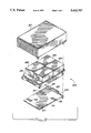
- FIG. 1 is an exploded view in perspective of a multiple disk drive system implemented in an industry-standard form factor according to the principles of the present invention
- FIG. 2 is a perspective view illustrating the disk drives mounted on the base of the system shown in FIG. 1;
- FIG. 3 is a perspective view illustrating the disk drive system of FIG. 1 in assembled form
- FIG. 4 is a rear view of the disk drive system shown in FIG. 3 illustrating the controller board connectors and the cover cooling vents;
- FIG. 5 is a top view illustrating a disk drive suitable for use in the multiple disk drive system shown in FIG. 1;
- FIG. 6 is an exploded view in perspective of the disk drive shown in FIG. 5;
- FIG. 7 is a conceptual block diagram of the electrical, control and communications distribution circuitry for the disk drive system shown in FIG. 1;
- FIG. 9 is a partially exploded view in perspective of a second embodiment of the multiple disk drive system of the present invention.
- the base 15 includes a mounting bracket 27 for mounting the HDAs 11 and 13 on the base.
- the HDAs 11 and 13 are mounted side-by-side on the base 15 and attached to bracket 27, for example, by stud 31 engaging slot 29 and secured by clip 35.
- Shock absorbing devices such as rubber shock absorber 33, for example, are provided at the HDAs 11 and 13 attachment points to provide mechanical isolation from the base 15.
- studs 37 and 39 engage slots 41 and 43, respectively; additional stud and clip combinations (not shown) or other suitable attachment means complete the attachment of the HDAs 11, 13 to the bracket 27.
- the base 15 also includes a mounting bracket 49 for mounting a vibration damping device 47.
- the vibration damper 47 is attached to the bracket 49 in such a manner that a force is applied to the front side 51 of each HDA housing 23, 25 when the lHDAs 11 and 13 are mounted on the base 15.
- the vibration damper device 47 comprises a stainless steel spring providing a controlled force acting on the HDA housings.
- the stainless steel spring is coated with a low-wear, insulating material, such as XYLAN 1010, to provide eiectricai insulation and a consistent coefficient of friction between the HDA housings 23, 25 and the vibration damper 47.
- the vibration damper 47 is rigidly secured to the mounting bracket 49 by bolts and nuts or other well-known manner.
- the vibration damper 47 applies a frictional dampening force in the range of 0.8 kilograms to 2.0 kilograms to the front side 51 of each HDA 11, 13.
- the frictional force applied by the vibration damper 47 minimizes the low frequency resonance of the individual HDAs 11, 13 and stiffens the HDA shock mounts, shock absorber 33, for example, to minimize transmission of vibration and shock between adjacent HDAs.
- the controller board 17 is mounted on the bottom side of the base 15. Siots 45 in the front edge of the board 17 engage corresponding studs or clips formed in the bottom side of the base 15 (not shown).
- the board 17 is retained in position by a rear mounting bracket 65 which engages the board at its rear edge and is secured to the base 15 in slots 67 by screws or boits and nuts 69 through tabs 71.
- the base 15 includes downwardly extending side and front walls 73 and 75, respectively, which form an enclosure for the controller board 17 when the bottom plate 21 is attached to the base 15.
- the front wall 75 includes a pattern of air or ventilation holes formed therethrough to provide a cooling air inlet for the controller board components.
- the top cover 19 is attached to the base 15 by slots 79 in engagement with screws or bolts and nuts 83 through holes 81.
- the bottom plate 21 is attached to the bottom side of the base 15 by tabs 85 in engagement with corresponding slots (not shown) in the lower portion of the base front wall 75 and maintained in position by screws or bolts and nuts 69 through slots 77 and 67 at the rear of the base.
- the two HDAs 11 and 13 are enclosed in an upper enclosure above the base 15 and the controller board 17 is enclosed in a lower enclosure below the base 15.
- the front and rear walls 87 and 89, respectively, of the cover 19 have a pattern of air or ventilation holes formed therethrough to allow cooling of the HDAs and associated components.
- the rear of the lower enclosure is open allowing cooling air to flow through the enclosure and to provide access to the controller board connectors 53, 55 and 57.
- the HDAs 11 and 13 utilized in the preferred embodiment described above have a length approximately equal to the width of a 51/4 inch disk drive form factor and a width approximately equal to one-half the length of a 51/4 inch disk drive form factor which are the approximate dimensions of a three and one-half (31/2) inch disk drive form factor.
- FIGS. 5 and 6 are a top plan view and an exploded view in perspective, respectively, of an HDA for a 31/2 inch form factor disk drive which is suitable for use in the muitiple disk drive system 10 of the present invention.
- a disk drive 100 includes a housing 101, and a housing cover 103 which, after assembly, is mounted on base 15 within bracket 27 (as shown in FIG. 1).
- Rotatably attached within the housing 101 on an actuator shaft 117 is an actuator arm assembly 119.
- One end of the actuator arm assembly 119 includes an E block or comb like structure 121 having a plurality of arms 123. Attached to the separate arms 123 on the comb or E block 121 are load springs 125. Attached at the end of each load spring is a slider 127 which carries a magnetic transducer head (not shown).
- a voice coil 129 On the other end of the actuator arm assembly 119 opposite the load springs 125 and the sliders 127 is a voice coil 129.
- a pair of magnets 131 Attached within the housing 101 is a pair of magnets 131.
- the pair of magnets 131 and the voice coil 129 are key components of a voice coil motor which applies a force to the actuator assembly 119 to rotate it about the actuator shaft 117.
- a spindle shaft 133 Also mounted within the housing 101 is a spindle shaft 133. Attached to the spindle shaft 133 are a number of magnetic storage disks 135.
- a spindle motor (not shown in FIG. 6) is coupled to the spindle shaft 133 for rotatory motion of the spindle shaft at a selected speed. As shown in FIG. 6, eight disks 135 are attached to the spindle shaft 133 in spaced apart relation.
- the separate arms 123 When assembled, the separate arms 123 extend between the disks 135 in such a manner that the magnetic head at the end of each load spring 125 is closely adjacent a surface of one of the disks.
- the voice coil motor responsive to control signals causes the magnetic head to be moved across the surface of the disk.
- the single electronics controller board or card 17 is mounted in the lower enclosure below the two HDAs 11 and 13 (as shown in FIG. 1) and is shared by the two HDAs.
- the two HDAs 11 and 13 will be referred to as drive A and drive B, respectively.
- Each drive A, B is electronically controlled by an interface microprocessor, a servo control microprocessor, several logic modules, digital/analog converters and various drivers and receivers and associated circuitry.
- the data channel circuitry which is mounted on a separate channel board 137 (as shown in FIG. 6) for each drive A, B, all of the control circuitry and components are mounted on the controller board 17.
- controller board 17 is divided into halves, one-half A, 149, providing control for drive A and the other half B, 151, provide control for drive B.
- the servo microprocessor (not shown) for each drive A, B generates all actuator servo and spindle motor control signals with tile exception of starting and stopping of the spindle.
- the servo microprocessor controls the spindle motor speed via a closed loop servo system and performs the spindle synchronization function.
- the servo microprocessor provides spindle motor control signals for its respective drive on lines 141 and 143, respectively.
- the spindle is driven directly by an in-hub, brushless DC drive motor 153 receiving its power from the controller board. Dynamic braking us utilized to quickly stop the spindle upon receipt of a stop signal.
- the actuator 155 is a swing-arm assembly driven by a voice coil motor having the read/write transducer heads mounted opposite the voice coil motor.
- the servo microprocessor initially conducts a power-up sequence and calibrates the actuator servo system. All actuator control signals providing closed loop control of transducer head positioning and tracking on the disk surface are generated by the servo microprocessor.
- a dedicated servo disk surface and head provides feedback to the actuator servo to maintain the read/write heads centered over the desired track on the disk.
- the servo microprocessor monitors the actuator position and determines a target track for a seek operation. Utilizing stored velocity profiles, the voice coil motor power amplifier driver is controlled to drive the actuator to a desired target track.
- the dedicated servo head During seek operations, the dedicated servo head provides track crossing information to the servo. Responsive to appropriate input conditions, the servo microprocessor generates control signals for accessing servo signal gating, recalibration, track following and error detection and recovery. The servo microprocessor provides servo control signals to its respective actuator servo via lines 145 and 147, respectively.
- the interface microprocessor (not shown) controls and interprets all interface signals between the host computer system controller and its respective drive.
- the interface microprocessor generates the spindle start and stop signals for its respective drive. All data processing circuitry and logic including coding for write and detection and decoding operations, error detection and error correction is implemented on a separate data channel board 137 (as shown in FIG. 6) for each drive A, B coupled to its microprocessor via lines 139A and 139B, respectively.
- the interface microprocessor controls the transfer of data between its respective drive A, B and the lost computer system, read/write access of the disk media and disk defect management and error recovery. Additionally, the interface microprocessor performs diagnostics and provides monitoring of the spindle status.
- the multiple disk drive unit 90 is coupled to the host computer system via the connectors 53, 55 and 57 mounted at the rear edge of the controller board 17.
- the controller board may use ANSI standardized SCSI or IPI interfaces in either differential or single-ended versions.
- single-ended buffered SCSI is utilized and the interface signal connector 55 comprises a 50-pin connector meeting ANSI/SCSI specifications (Molex part no. 70246 is suitable for this purpose).
- the pin assignments are given in Table I.
- the DC power connector 53 comprises a 4-pin connector which couples +12 volt and +5 volt power to the board 17 and provides two system grounds.
- the options block 57 comprises a 26-pin jumper block 57 as shown in FIG. 8.
- Pins A1-A6 and B1-B6 are used to select and set the respective drive A, B SCSI device address (SCSI ID).
- the desired address is set utilizing a jumper or shorting block 161, shunting one or more of the bit pins to ground.
- Pin configuration for a desired drive address is defined in Table I.
- Pins A9, A10 and B9, B10 control spindle synchronization and the remaining pins control spindle motor start and term power for the respective A and B drives.
- the multiple disk drive unit 90 provides a two-drive array utilizing a common controller board and a common interface connector in a 51/4 disk drive form factor.
- the two-drive array may be controlled in various configurations to provide optimum performance or user desired features.
- the configuration of the preferred embodiment comprises two separately addressable independent disk drives accessed through a common SCSI connector.
- the address (SCSI ID) of each drive A, B is set at the jumper block 57 as described above.
- a user then may use one drive, drive A, for example, while reserving the other drive as a "hot" spare.
- both drive A and drive B may be used for continuous data storage thus providing greater storage capacity than provided by a single 51/4 inch drive while reducing the power and cooling requirements and the cables, connectors, etc., required for two 31/2 inch drives.
- a multiple disk drive system 200 comprises a base 201 having four HDAs 203, 205, 207 and 209 mounted on an upper side thereof and a single controller board 211 providing the circuitry and components required for the operation and control of the four HDAs. Cable connector pairs 213, 215, 217 and 219 are provided to couple power and control signals to and transfer data to and from the HDAs 209, 203, 205 and 207, respectively. Power connector 221 and interface connector 223 are mounted at the rear edge of the controller board 211 to couple the multiple disk drive system 200 to a host computer system. As described above with reference to FIG.
- the controller board 211 is mounted on tile bottom side of the base 201 beneath the HDAs. Similarly, a top cover 227 and a bottom cover (as shown in FIG. 1) are attached to the base 201 forming upper and lower enclosures which enclose the four HDAs and the controller board, respectively.
- a complete disk drive unit 90 is formed (as shown in FIG. 4) which provides an array of four separately addressable, independent disk drives accessible via a common interface connector.
- the disk drive unit 90 has approximately the overall dimensions of a 51/4 inch disk drive form factor (as shown in FIG. 4).
- Each of the four HDAs 203, 205, 207 and 209 mounted on base 201 has a length approximately equal to one-half the length of a 51/4 inch drive form factor and a width approximately equal to one-haif the width of a 51/4 inch disk drive form factor, which length and width approximate the dimensions of a two and one-half (21/2) inch disk drive form factor.
Abstract
A multiple disk drive system having two disk-head assemblies (HDA) internally mounted on a rigid frame and accessible via a common industry-standard interface connector is provided. Each HDA is enclosed in a separate housing which is mounted on the disk drive system frame. A vibration damper mounted on the disk drive system frame physically contacts each HDA housing providing a spring force which minimizes the effects of shock and vibration on the operation of the HDAs. The vibration damper is coated with a low-wear, electrically insulating material to provide electrical isolation between the vibration damper and the HDAs housings. The coating material is chosen to also provide a desired coefficient of friction between the vibration damper and the HDA housings. A single electronic controller board is shared by both HDAs and is mounted on the bottom side of the frame underlying the HDAs. The controller board may implement SCSI or IPI interfaces in either differential or single-ended versions. The assembly is fully enclosed with metal top and bottom covers to provide separate enclosures for the HDAs, controller board cooling and EMC and RFI protection.
Description
This is a divisional application of application Ser. No. 08/179,884 filed on Jan. 10, 1994, now abandoned, which is a continuation of application Ser. No. 07/850,321 filed on Mar. 10, 1992, now abandoned.
The present invention relates generally to multiple digital data storage device systems and, more particularly, to at least two high capacity disk drive data storage devices having a specified physical size mounted in a larger standardized form factor package forming a single unit.
One of the principle components of a computer system is a place to store data. Typically computer systems employ a number of storage means to store data for use by a computer system. For example, a computer system can store data in a peripheral storage device referred to as a disk drive or direct access storage device (DASD).
A disk drive or DASD includes one or more disks which appear similar to records utilized with a record player or compact disks (CD) which are utilized with a CD player. The disks are stacked on a spindle for rotary motion in parallel planes, much like records. In a disk drive, however, the disks are mounted to the spindle and spaced apart so that the separate disks do not touch each other.
Such data storage devices employing rotating magnetic or optical media disks are well-known for high capacity, low cost storage of data. Such disks typically have a multiplicity of concentric data track locations formed on one or both surfaces, each capable of storing useful information. The information stored in each track is accessed by a transducer head which is moved among the tracks during track seeking operations and which is maintained in alignment with the track during read only and/or read/write track following operations of the device. Typically one or more transducer heads are provided for each data storage surface. The electro-mechanical assembly for rotation of the disk relative to the head and for moving the head radially relative to the disk surface for track accessing purposes is referred to as the head and disk assembly (HDA). A control mechanism is provided in order to maintain the head within the boundaries of each data track, and may take the form of detents provided by a stepping motor, or by a continuously positionable actuator operating within a closed loop servo, or a time-sampled servo. Additionally, an interface device is required for connection of the HDA to a controller and for communication between the disk drive and the computer system. Typically, a standardized interface is utilized, for example, the Small Computer Synchronous Interface (SCSI).
Today's technology relating to data storage is marked by continuing trends towards standardization and towards increased storage capacity, reduced data storage device weight and size, and reduced power consumption. Standardization in size, referred to as form factor, and in interface compatibility is being pursued by manufacturers of both desktop systems such as personal computer (PC) and workstation systems and larger computing systems. Thus, disk drives having differing capabilities and capacities provided in standard form factors and plug-in configurations by several different manufacturers may be used interchangeably in different PC's, for example, in standardized plug-in slots provided by the PC manufacturers.
Increasing system storage capacity while reducing disk drive size requires careful balancing of the reduction of the area of the storage medium, i.e., the area of the disk surface, against the corresponding reduction in storage capacity. Typically, the tradeoff is to increase the number of disks per spindle and/or increase the number of disk drives. On a iarge scale, large numbers of relatively small disk drives are mounted in drawers to provide high storage capacity while taking advantage of common power supplies and cooling facilities, for example, to achieve an overall reduction in power requirements. However, for a PC, for example, a user is limited to adding individual disk drives in the standard form factor slots provided by the PC manufacturer or by adding relatively expensive stand-alone units.
It is therefore a principal object of the present invention to provide a disk drive assembly in an industry-standard form factor which includes at least two HDAs.
A further object of the present invention is to provide a disk drive assembly in a five and one-quarter (51/4) inch disk drive form factor which includes two three and one-half (31/2) inch form factor HDAs mounted on a common frame.
A still further object of the present invention is to provide a disk drive assembly including at least two HDAs and further including a single controller board.
Another object of the present invention is to provide a disk drive assembly including at least two HDAs which are separately addressable via a common interface connector.
Another object of the present invention is to provide a disk drive assembly including at least two HDAs packaged in an industry-standard form factor which is interchangeable with disk drives of the same form factor in a computer system in slots and racks of the same form factor as provided by the computer system manufacturers.
These and other objects of the present invention are accomplished by a multiple disk drive assembly comprising a mounting frame or base having a length approximately equal to the length of a selected disk drive form factor and a width approximately equal to the width of the selected disk drive form factor and havlng two HDAs mounted on a top side thereof, each of the HDAs having a length approximately equal to the width of the selected disk drive form factor and a width approximately equal to one-half of the length of tile selected disk drive form factor. The multiple disk drive assembly further includes a single, common controller board mounted on the bottom side of the base underlying the two HDAs and having common power and interface connectors mounted at a rear edge of the controller board. A common jumper or option block also mounted at the rear edge of the controller board provides for setting separate addresses for each of the HDAs. Top and bottom covers attached to the top and bottom sides of the base, respectively, form upper and lower enclosures enclosing the HDAs and the controller board and providing a disk drive assembly unit having overall outside dimensions approximately equal to the selected disk drive form factor.
The multiple disk drive assembly of the present invention provides a 51/4 inch disk drive form factor assembly having two 31/2 inch disk drive form factor HDAs internally mounted on a rigid frame and accessible via a common industry-standard interface. Both the interface and power connectors and the frame mounting hole patterns are industry standard to provide interchangeability with 51/4 form factor disk drives provided by manufacturers for use in computer systems, such as desktop personal computers, for example. A single electronic controller board is shared by the two HDAs to provide all controller functions and power distribution for the HDAs as well as data transfer to and from the data channel for each HDA. The controller board may be implemented with either SCSI or IPI interfaces in single-ended or differential versions. Top and bottom covers provide the assembly with upper and lower enclosures with sufficient clearance around the HDAs and controller board, respectively, to provide efficient cooling of the components utilizing the cooling provided by the host computer system. A spring vibration damper device is utilized to minimize both external and internal vibration and shock effects to the HDAs. The assembly is fully enclosed with metal covers to provide EMC and RFI protection.
The present invention provides a two-drive array in a singie assembly within the constraints of a 51/4 inch industry-standard form factor having common electronics and accessibie via a common interface connector. The performance of the array may be optimized for various configurations without forcing a user of the assembly to rewrite or amend their computer operating system software or providing special controllers or interfaces. For example, the two-drive assembly provides two independently addressable disk drives which may be utilized as two separate data storage files or in which one drive may be reserved as a "hot" spare while the other drive is used for data storage. Alternatively, the two-drive array may be configured to provide a "single" drive with the media rate effectively doubled or as one drive with multiple coples of data (mirrored data).
The two-drive assembly of the present invention provides as great or greater storage capacity than a like sized 51/4 inch disk drive while consuming less power. Additionally, since the spindle drive motor for a 31/2 inch disk drive is significantly smaller that the spindle motor for a 51/4 inch disk drive and startup can be staggered, less startup current is required.
The foregoing and other objects, features and advantages of the present invention will be apparent from the following detailed description of the preferred embodiments of the invention, reference being made to the accompanying drawings, in which like reference numerals indicate like parts and in which:
FIG. 1 is an exploded view in perspective of a multiple disk drive system implemented in an industry-standard form factor according to the principles of the present invention;
FIG. 2 is a perspective view illustrating the disk drives mounted on the base of the system shown in FIG. 1;
FIG. 3 is a perspective view illustrating the disk drive system of FIG. 1 in assembled form;
FIG. 4 is a rear view of the disk drive system shown in FIG. 3 illustrating the controller board connectors and the cover cooling vents;
FIG. 5 is a top view illustrating a disk drive suitable for use in the multiple disk drive system shown in FIG. 1;
FIG. 6 is an exploded view in perspective of the disk drive shown in FIG. 5;
FIG. 7 is a conceptual block diagram of the electrical, control and communications distribution circuitry for the disk drive system shown in FIG. 1;
FIG. 8 is a plan view of the jumper block for the controller board shown in FIG. 7; and
FIG. 9 is a partially exploded view in perspective of a second embodiment of the multiple disk drive system of the present invention.
Referring to FIGS. 1 and 2, FIG. 1 is an exploded view of a preferred embodiment of the multiple disk drive system according to the principles of the present invention. The multiple disk drive system 10 comprises two head and disk assemblies (HDA) 11 and 13 mounted on the top side a mounting frame or base 15, a common controller board 17 mounted on the bottom side of the base 15 and including a top cover 19 and a bottom plate 21 attached to the top and bottom of the base 15, respectively, to provide an enclosure for the two HDAs 11 and 13 and the controller board 17. Each of the HDAs 11, 13 is enclosed in a separate housing 23, 25, respectively, which provides a rigid frame for mounting the spindle and attached disks, the spindle motor and the actuator and read/write transducer head assembly as will be described in greater detail below with reference to FIGS. 5 and 6. The base 15 includes a mounting bracket 27 for mounting the HDAs 11 and 13 on the base. The HDAs 11 and 13 are mounted side-by-side on the base 15 and attached to bracket 27, for example, by stud 31 engaging slot 29 and secured by clip 35. Shock absorbing devices, such as rubber shock absorber 33, for example, are provided at the HDAs 11 and 13 attachment points to provide mechanical isolation from the base 15. Similarly, studs 37 and 39 engage slots 41 and 43, respectively; additional stud and clip combinations (not shown) or other suitable attachment means complete the attachment of the HDAs 11, 13 to the bracket 27.
The base 15 also includes a mounting bracket 49 for mounting a vibration damping device 47. The vibration damper 47 is attached to the bracket 49 in such a manner that a force is applied to the front side 51 of each HDA housing 23, 25 when the lHDAs 11 and 13 are mounted on the base 15. The vibration damper device 47 comprises a stainless steel spring providing a controlled force acting on the HDA housings. The stainless steel spring is coated with a low-wear, insulating material, such as XYLAN 1010, to provide eiectricai insulation and a consistent coefficient of friction between the HDA housings 23, 25 and the vibration damper 47. The vibration damper 47 is rigidly secured to the mounting bracket 49 by bolts and nuts or other well-known manner.
When mounting two or more HDAs on a common frame, base 15, for example, the frame must be sufficiently rigid to minimize effects due to both external vibration and shock and to vibrational forces generated by the HDAs themselves. For example, rotational torque generated by the rotating magnetic disks is transmitted to the HDA housing causing low frequency vibrations. This vibration may also be transmitted to adjacent HDAs via the mounting frame. One result of such vibration is track misregistration greatly increasing the demands on the head tracking servo system. The use of dampening systems, such as the vibration dampening device 47, for example, reduces the rigidity and stiffness requirements of the mounting frame resulting in a lighter, less massive frame and allowing a greater choice of materials for fabrication of the mounting frame. In the preferred embodiment, the vibration damper 47 applies a frictional dampening force in the range of 0.8 kilograms to 2.0 kilograms to the front side 51 of each HDA 11, 13. The frictional force applied by the vibration damper 47 minimizes the low frequency resonance of the individual HDAs 11, 13 and stiffens the HDA shock mounts, shock absorber 33, for example, to minimize transmission of vibration and shock between adjacent HDAs.
The controller board 17 comprises a multi-layer printed circuit board having various electronic components mounted thereon and provides the required electronic circuitry to facilitate operation and control of the HDAs 11 and 13, couple information to and from the HDAs and to interface with a host computer system. The controller board 17 also includes a power connector 53, a controller interface connector 55 and a jumper block or options connector 57 mounted thereon at the rear end of the board. Cables 59 connect the controller board to the HDAs 11 and 13 and to the data channel boards 61 and 63, respectively, mounted on the HDA housings. The controller board 17 is described in greater detail beiow with reference to FIG. 7.
Referring now also to FIGS. 3 and 4, the controller board 17 is mounted on the bottom side of the base 15. Siots 45 in the front edge of the board 17 engage corresponding studs or clips formed in the bottom side of the base 15 (not shown). The board 17 is retained in position by a rear mounting bracket 65 which engages the board at its rear edge and is secured to the base 15 in slots 67 by screws or boits and nuts 69 through tabs 71. The base 15 includes downwardly extending side and front walls 73 and 75, respectively, which form an enclosure for the controller board 17 when the bottom plate 21 is attached to the base 15. The front wall 75 includes a pattern of air or ventilation holes formed therethrough to provide a cooling air inlet for the controller board components.
The top cover 19 is attached to the base 15 by slots 79 in engagement with screws or bolts and nuts 83 through holes 81. The bottom plate 21 is attached to the bottom side of the base 15 by tabs 85 in engagement with corresponding slots (not shown) in the lower portion of the base front wall 75 and maintained in position by screws or bolts and nuts 69 through slots 77 and 67 at the rear of the base. When completely assembled, the two HDAs 11 and 13 are enclosed in an upper enclosure above the base 15 and the controller board 17 is enclosed in a lower enclosure below the base 15. The front and rear walls 87 and 89, respectively, of the cover 19 have a pattern of air or ventilation holes formed therethrough to allow cooling of the HDAs and associated components. The rear of the lower enclosure is open allowing cooling air to flow through the enclosure and to provide access to the controller board connectors 53, 55 and 57.
The assembled multiple disk drive system, as shown in FIG. 4, forms a complete plug-in disk drive unit 90 having overall dimensions of approximately 3.25 inches (82.5 millimeters (mm)) in height, 5.75 inches (146.0 mm) in width and 8.25 inches (209.5 mm) in length, the approximate dimensions of the industry-standard form factor for a five and one-quarter (51/4 ) inch disk drive. An industry-standard pattern of mounting holes are provided which allows the disk drive unit 90 to be mounted in six different positions. The controller board connectors 53, 55 and 57 comprise industry-standard components. The disk drive unit 90 is completely interchangeable with other industry-standard 51/4 inch form factor disk drives and can be used in any 51/4 inch slot or rack in a computer, such as a PC for example.
The HDAs 11 and 13 utilized in the preferred embodiment described above have a length approximately equal to the width of a 51/4 inch disk drive form factor and a width approximately equal to one-half the length of a 51/4 inch disk drive form factor which are the approximate dimensions of a three and one-half (31/2) inch disk drive form factor. FIGS. 5 and 6 are a top plan view and an exploded view in perspective, respectively, of an HDA for a 31/2 inch form factor disk drive which is suitable for use in the muitiple disk drive system 10 of the present invention.
Referring now to FIGS. 5 and 6, a disk drive 100 includes a housing 101, and a housing cover 103 which, after assembly, is mounted on base 15 within bracket 27 (as shown in FIG. 1). Rotatably attached within the housing 101 on an actuator shaft 117 is an actuator arm assembly 119. One end of the actuator arm assembly 119 includes an E block or comb like structure 121 having a plurality of arms 123. Attached to the separate arms 123 on the comb or E block 121 are load springs 125. Attached at the end of each load spring is a slider 127 which carries a magnetic transducer head (not shown). On the other end of the actuator arm assembly 119 opposite the load springs 125 and the sliders 127 is a voice coil 129.
Attached within the housing 101 is a pair of magnets 131. The pair of magnets 131 and the voice coil 129 are key components of a voice coil motor which applies a force to the actuator assembly 119 to rotate it about the actuator shaft 117. Also mounted within the housing 101 is a spindle shaft 133. Attached to the spindle shaft 133 are a number of magnetic storage disks 135. A spindle motor (not shown in FIG. 6) is coupled to the spindle shaft 133 for rotatory motion of the spindle shaft at a selected speed. As shown in FIG. 6, eight disks 135 are attached to the spindle shaft 133 in spaced apart relation. When assembled, the separate arms 123 extend between the disks 135 in such a manner that the magnetic head at the end of each load spring 125 is closely adjacent a surface of one of the disks. During storing and retrieving (write/read) of information, the voice coil motor responsive to control signals causes the magnetic head to be moved across the surface of the disk.
Referring now also to FIG. 7, the single electronics controller board or card 17 is mounted in the lower enclosure below the two HDAs 11 and 13 (as shown in FIG. 1) and is shared by the two HDAs. For the purposes of the description of the controller board 17, the two HDAs 11 and 13 will be referred to as drive A and drive B, respectively. Each drive A, B is electronically controlled by an interface microprocessor, a servo control microprocessor, several logic modules, digital/analog converters and various drivers and receivers and associated circuitry. With the exception of the data channel circuitry which is mounted on a separate channel board 137 (as shown in FIG. 6) for each drive A, B, all of the control circuitry and components are mounted on the controller board 17. While some of the components physically may be shared by the two drives A, B for efficiency and parts reduction, logically, the controller board 17 is divided into halves, one-half A, 149, providing control for drive A and the other half B, 151, provide control for drive B.
Since the control electronics for both of the drives is essentially identical, both in operation and composition, the operation of only one will be described.
The servo microprocessor (not shown) for each drive A, B generates all actuator servo and spindle motor control signals with tile exception of starting and stopping of the spindle. The servo microprocessor controls the spindle motor speed via a closed loop servo system and performs the spindle synchronization function. The servo microprocessor provides spindle motor control signals for its respective drive on lines 141 and 143, respectively. The spindle is driven directly by an in-hub, brushless DC drive motor 153 receiving its power from the controller board. Dynamic braking us utilized to quickly stop the spindle upon receipt of a stop signal.
The actuator 155 is a swing-arm assembly driven by a voice coil motor having the read/write transducer heads mounted opposite the voice coil motor. The servo microprocessor initially conducts a power-up sequence and calibrates the actuator servo system. All actuator control signals providing closed loop control of transducer head positioning and tracking on the disk surface are generated by the servo microprocessor. A dedicated servo disk surface and head provides feedback to the actuator servo to maintain the read/write heads centered over the desired track on the disk. The servo microprocessor monitors the actuator position and determines a target track for a seek operation. Utilizing stored velocity profiles, the voice coil motor power amplifier driver is controlled to drive the actuator to a desired target track. During seek operations, the dedicated servo head provides track crossing information to the servo. Responsive to appropriate input conditions, the servo microprocessor generates control signals for accessing servo signal gating, recalibration, track following and error detection and recovery. The servo microprocessor provides servo control signals to its respective actuator servo via lines 145 and 147, respectively.
The interface microprocessor (not shown) controls and interprets all interface signals between the host computer system controller and its respective drive. The interface microprocessor generates the spindle start and stop signals for its respective drive. All data processing circuitry and logic including coding for write and detection and decoding operations, error detection and error correction is implemented on a separate data channel board 137 (as shown in FIG. 6) for each drive A, B coupled to its microprocessor via lines 139A and 139B, respectively. The interface microprocessor controls the transfer of data between its respective drive A, B and the lost computer system, read/write access of the disk media and disk defect management and error recovery. Additionally, the interface microprocessor performs diagnostics and provides monitoring of the spindle status.
The multiple disk drive unit 90 is coupled to the host computer system via the connectors 53, 55 and 57 mounted at the rear edge of the controller board 17. The controller board may use ANSI standardized SCSI or IPI interfaces in either differential or single-ended versions. In the preferred embodiment, single-ended buffered SCSI is utilized and the interface signal connector 55 comprises a 50-pin connector meeting ANSI/SCSI specifications (Molex part no. 70246 is suitable for this purpose). The pin assignments are given in Table I. The DC power connector 53 comprises a 4-pin connector which couples +12 volt and +5 volt power to the board 17 and provides two system grounds.
              TABLE I
______________________________________
             Conductor
             Pin
Signal Name  Number             Signal Name
______________________________________
GROUND        1      2
DB(0)
GROUND        3      4
DB(1)
GROUND        5      6
DB(2)
GROUND        7      8
DB(3)
GROUND        9     10
DB(4)
GROUND       11     12
DB(5)
GROUND       13     14
DB(6)
GROUND       15     16
DB(7)
GROUND       17     18
DB(P)
GROUND       19     20          GROUND
GROUND       21     22          GROUND
OPEN         23     24          OPEN
OPEN         25     26          TERMPWR
OPEN         27     28          OPEN
GROUND       29     30          GROUND
GROUND       31     32
ATN
GROUND       33     34          GROUND
GROUND       35     36
BSY
GROUND       37     38
ACK
GROUND       39     40
RST
GROUND       41     42
MSG
GROUND       43     44
SEL
GROUND       45     46
C/D
GROUND       47     48
REQ
GROUND       49     50
I/0
______________________________________
The options block 57 comprises a 26-pin jumper block 57 as shown in FIG. 8. Pins A1-A6 and B1-B6 are used to select and set the respective drive A, B SCSI device address (SCSI ID). The desired address is set utilizing a jumper or shorting block 161, shunting one or more of the bit pins to ground. Pin configuration for a desired drive address is defined in Table I. Pins A9, A10 and B9, B10 control spindle synchronization and the remaining pins control spindle motor start and term power for the respective A and B drives.
TABLE II ______________________________________ ADDRESS DETERMINATION BIT0 BIT1 BIT2 ADDRESS ______________________________________ off off off 0 on off off 1 off onoff 2 on on off 3 off off on 4 on off on 5 off on on 6 on on on 7 ______________________________________ Note: In the chart above "off" means jumper is not in place and "on" means jumper is in place.
The multiple disk drive unit 90 provides a two-drive array utilizing a common controller board and a common interface connector in a 51/4 disk drive form factor. The two-drive array may be controlled in various configurations to provide optimum performance or user desired features. The configuration of the preferred embodiment comprises two separately addressable independent disk drives accessed through a common SCSI connector. The address (SCSI ID) of each drive A, B is set at the jumper block 57 as described above. A user then may use one drive, drive A, for example, while reserving the other drive as a "hot" spare. Alternatively, both drive A and drive B may be used for continuous data storage thus providing greater storage capacity than provided by a single 51/4 inch drive while reducing the power and cooling requirements and the cables, connectors, etc., required for two 31/2 inch drives.
Referring now to FIG. 9, a second preferred embodiment of a multiple disk drive system according to the principles of the present invention is shown. A multiple disk drive system 200 comprises a base 201 having four HDAs 203, 205, 207 and 209 mounted on an upper side thereof and a single controller board 211 providing the circuitry and components required for the operation and control of the four HDAs. Cable connector pairs 213, 215, 217 and 219 are provided to couple power and control signals to and transfer data to and from the HDAs 209, 203, 205 and 207, respectively. Power connector 221 and interface connector 223 are mounted at the rear edge of the controller board 211 to couple the multiple disk drive system 200 to a host computer system. As described above with reference to FIG. 1, the controller board 211 is mounted on tile bottom side of the base 201 beneath the HDAs. Similarly, a top cover 227 and a bottom cover (as shown in FIG. 1) are attached to the base 201 forming upper and lower enclosures which enclose the four HDAs and the controller board, respectively. When assembled, a complete disk drive unit 90 is formed (as shown in FIG. 4) which provides an array of four separately addressable, independent disk drives accessible via a common interface connector.
In the preferred embodiment as described above with reference to FIG. 9, the disk drive unit 90 has approximately the overall dimensions of a 51/4 inch disk drive form factor (as shown in FIG. 4). Each of the four HDAs 203, 205, 207 and 209 mounted on base 201 has a length approximately equal to one-half the length of a 51/4 inch drive form factor and a width approximately equal to one-haif the width of a 51/4 inch disk drive form factor, which length and width approximate the dimensions of a two and one-half (21/2) inch disk drive form factor.
While the invention has been particularly shown and described with reference to various preferred embodiments thereof, it is understood by those skilled in the art that the invention is not to be limited to the disclosed embodiments, but that various modifications in the form and details may be made therein without departing from the spirit and scope of the appended claims.
Claims (13)
1. A multiple disk drive system comprising:
a base;
a number N of disk drives for storing information, said N disk drives mounted on a top side of said base;
a single vibration damper member mounted on said base for coupling a force to each of said disk drives for minimizing the effects of shock and vibration on the operation of said N disk drives, said vibration damper member being coated with a layer of electrically insulating material insulating said vibration damper member from said N disk drives;
control means coupled to said N disk drives for providing control signals; and
data means for coupling information to and from said N disk drives in response to said control signals.
2. A multiple disk drive system as in claim 1 further comprising a common controller board mounted on a bottom side of said base underlying said N disk drives, said controller means and said data means mounted thereon.
3. A multiple disk drive system as in claim 2 wherein said vibration damper means comprises spring means for applying a frictional force to each of said N disk drives.
4. A multiple disk drive system as in claim 3 wherein said electrically insulating material provides a selected coefficient of friction between said spring means and each said disk drive.
5. A multiple disk drive system as in claim 3 wherein said spring means comprises a single-piece stainless steel spring member mounted to said steel base.
6. A multiple disk drive system comprising:
a base;
a number of N of disk drives for storing information, said N disk drives mounted on a top side of said base; and
a single vibration damper member mounted on said base for coupling a force to each of said disk drives for minimizing the effects of shock and vibration on the operation of said N disk drives, said vibration damper member being coated with a layer of electrically insulating material insulating said vibration damper member from said N disk drives.
7. A multiple disk drive system as in claim 6 wherein said vibration damper means comprises spring means for applying a frictional force to each of said N disk drives.
8. A multiple disk drive system as in claim 7 wherein said electrically insulating material provides a selected coefficient of friction between said spring means and each said disk drive.
9. A multiple disk drive system as in claim 7 wherein said spring means comprises a single-piece stainless steel spring member mounted to said base.
10. A multiple disk drive system comprising:
a base;
two disk drives mounted on a top side of said base, each of said disk drives enclosed in a separate housing for mounting to said base;
a single-piece spring member mounted on said base and contacting each said separate housing at a selected point for coupling a frictional force to each of said two disk drives at said selected point of contact, said spring member for minimizing the effects of shock and vibration on the operation of said two disk drives;
said spring member being coated with a layer of low-wear, electrically insulating material for electrically insulating said spring member from said two disk drives and for providing a selected coefficient of friction between said spring member and each said disk drive at said point of contact;
control means coupled to said two disk drives for providing control signals; and
data means for coupling information to and from said two disk drives in response to said control signals.
11. A multiple disk drive system as in claim 10 wherein said spring member is of stainless steel.
12. A multiple disk drive system comprising:
a base
two disk drives for storing information mounted on a top side of said base, each of said two disk drives enclosed in a separate housing;
a single-piece spring member mounted on said base and contacting each said separate housing at a selected point for coupling a frictional force to each of said two disk drives at said selected point of contact, said spring member for minimizing the effects of shock and vibration on the operation of said two disk drives; and
said spring member being coated with a layer of low-wear, electrically insulating material for electrically insulating said spring member from said two disk drive and for providing a selected coefficient of friction between said spring member and each said disk drive at said point of contact.
13. A multiple disk drive system as in claim 12 wherein said spring member is of stainless steel.
Priority Applications (1)
| Application Number | Priority Date | Filing Date | Title |
|---|---|---|---|
| US08/243,722 US5422767A (en) | 1992-03-10 | 1994-05-17 | Vibration damper for a multiple disk drive unit |
Applications Claiming Priority (3)
| Application Number | Priority Date | Filing Date | Title |
|---|---|---|---|
| US85032192A | 1992-03-10 | 1992-03-10 | |
| US17988494A | 1994-01-10 | 1994-01-10 | |
| US08/243,722 US5422767A (en) | 1992-03-10 | 1994-05-17 | Vibration damper for a multiple disk drive unit |
Related Parent Applications (1)
| Application Number | Title | Priority Date | Filing Date |
|---|---|---|---|
| US17988494A Division | 1992-03-10 | 1994-01-10 |
Publications (1)
| Publication Number | Publication Date |
|---|---|
| US5422767A true US5422767A (en) | 1995-06-06 |
Family
ID=25307818
Family Applications (1)
| Application Number | Title | Priority Date | Filing Date |
|---|---|---|---|
| US08/243,722 Expired - Lifetime US5422767A (en) | 1992-03-10 | 1994-05-17 | Vibration damper for a multiple disk drive unit |
Country Status (10)
| Country | Link |
|---|---|
| US (1) | US5422767A (en) |
| EP (1) | EP0560529B1 (en) |
| JP (1) | JP2682558B2 (en) |
| KR (1) | KR970004657B1 (en) |
| CN (1) | CN1027560C (en) |
| AT (1) | ATE166486T1 (en) |
| CA (1) | CA2091082A1 (en) |
| DE (1) | DE69318605T2 (en) |
| MY (1) | MY108759A (en) |
| SG (1) | SG44367A1 (en) |
Cited By (19)
| Publication number | Priority date | Publication date | Assignee | Title |
|---|---|---|---|---|
| US5858509A (en) * | 1996-11-15 | 1999-01-12 | Digital Equipment Corporation | Attenuating vibrations in a mounting shelf for multiple disk drives |
| US5926366A (en) * | 1996-11-15 | 1999-07-20 | Digital Equipment Corporation | Tab and slot disk drive vibration reduction structure |
| US6022224A (en) * | 1998-07-22 | 2000-02-08 | International Business Machines Corporation | Shock mount connector for head disk assembly |
| US6209842B1 (en) * | 1998-05-27 | 2001-04-03 | International Business Machines Corporation | Laminated damping device for a carrier |
| US6283438B1 (en) * | 1998-03-13 | 2001-09-04 | Matsushita Electric Industrial Co., Ltd. | Shock absorbing holder and information processor having same |
| US6320744B1 (en) | 1999-02-19 | 2001-11-20 | General Dynamics Information Systesm, Inc. | Data storage housing |
| US6496326B1 (en) | 1999-06-11 | 2002-12-17 | Seagate Technology Llc | Noise and vibration reduction in computer disk drives |
| US6594724B1 (en) | 2000-03-30 | 2003-07-15 | Hitachi Global Storage Technologies Netherlands B.V. | Enhanced DASD with smaller supplementary DASD |
| US6628469B1 (en) | 2000-07-11 | 2003-09-30 | International Business Machines Corporation | Apparatus and method for low power HDD storage architecture |
| US6697213B2 (en) | 2000-03-31 | 2004-02-24 | Seagate Technology Llc | Cover including multiple cover plates with damped layers |
| US20040075932A1 (en) * | 2002-10-16 | 2004-04-22 | Watson Scott Edward | Integrated magnetic data storage and optical disk data storage device |
| US20040129005A1 (en) * | 2002-04-12 | 2004-07-08 | Johnson Richard J. | Rack-mounted equipment cooling |
| US6809895B1 (en) * | 1998-01-15 | 2004-10-26 | Samsung Electronics Co., Ltd. | Hard disk drive having a plurality of head disk assemblies |
| US20060002004A1 (en) * | 2004-06-30 | 2006-01-05 | Albrecht David W | Hard disk drive (HDD) assembly of small form-factor HDD shock-mounted in frame having dimensions of larger form-factor HDD |
| US20060002076A1 (en) * | 2004-06-30 | 2006-01-05 | Albrecht David W | Shock mount assembly for attachment of an electronic device to a support structure |
| US20060139877A1 (en) * | 2004-12-29 | 2006-06-29 | Mark Germagian | Rack height cooling |
| US20060268444A1 (en) * | 2005-05-31 | 2006-11-30 | Seagate Technology Llc | High speed and high capacity data storage array |
| US7325410B1 (en) | 2004-11-19 | 2008-02-05 | American Power Conversion Corporation | IT equipment cooling |
| US7436658B1 (en) * | 2005-03-22 | 2008-10-14 | Adtron Corporation | Mounting for dual hard drives |
Families Citing this family (6)
| Publication number | Priority date | Publication date | Assignee | Title |
|---|---|---|---|---|
| US5893048A (en) * | 1997-01-13 | 1999-04-06 | Dell Usa, L. P. | Method and apparatus for identifying vibration level of previously tested CD ROM discs |
| US6900962B1 (en) * | 1997-09-05 | 2005-05-31 | Seagate Technology Llc | High performance standard configuration disc drive having smaller-than-standard discs |
| US6618254B2 (en) | 2001-09-05 | 2003-09-09 | Hewlett-Packard Development Company, L.P. | Methods and apparatus for securing disk drives in a disk array |
| US7296117B2 (en) | 2004-02-12 | 2007-11-13 | International Business Machines Corporation | Method and apparatus for aggregating storage devices |
| US7296116B2 (en) | 2004-02-12 | 2007-11-13 | International Business Machines Corporation | Method and apparatus for providing high density storage |
| GB2424308A (en) * | 2005-03-14 | 2006-09-20 | Jozef Vagovic | Dual hard disc drive |
Citations (12)
| Publication number | Priority date | Publication date | Assignee | Title |
|---|---|---|---|---|
| GB204299A (en) * | 1922-09-22 | 1924-03-06 | Bliss E W Co | Improvements in key clutches |
| US4367502A (en) * | 1980-04-11 | 1983-01-04 | Shugart Technology | Fixed hard disc drive assembly and clean air system |
| GB2190531A (en) * | 1986-04-23 | 1987-11-18 | Rodime Plc | 3 <1>/2 inch Winchester disc drive |
| US4908715A (en) * | 1988-03-29 | 1990-03-13 | Magnetic Peripherals Inc. | Disk drive unit |
| US4912580A (en) * | 1984-01-17 | 1990-03-27 | Norand Corporation | Information storage system with readily removable high capacity disk drive unit |
| US4979062A (en) * | 1987-05-29 | 1990-12-18 | Conner Peripherals, Inc. | Disk drive architecture |
| US5025336A (en) * | 1989-11-06 | 1991-06-18 | Prairietek Corporation | Disk drive apparatus |
| US5041931A (en) * | 1988-09-01 | 1991-08-20 | Fujitsu Limited | Plural disc arrangement and cooling system therefore |
| EP0464550A2 (en) * | 1990-06-25 | 1992-01-08 | Kabushiki Kaisha Toshiba | A computer system having storage devices |
| WO1992009077A1 (en) * | 1990-11-09 | 1992-05-29 | Conner Peripherals, Inc. | Multiple actuator disk drive |
| US5173819A (en) * | 1988-10-05 | 1992-12-22 | Hitachi, Ltd. | Disk apparatus having an improved cooling structure |
| US5214567A (en) * | 1991-12-19 | 1993-05-25 | Intel Corporation | Modular peripheral platform having two disk drives and one electrical connector |
Family Cites Families (12)
| Publication number | Priority date | Publication date | Assignee | Title |
|---|---|---|---|---|
| JPS58212684A (en) * | 1982-06-04 | 1983-12-10 | Nec Corp | Magnetic disc device |
| JPS5933667A (en) * | 1982-08-16 | 1984-02-23 | Tokyo Electric Co Ltd | Floppy disk controller |
| JPS63257986A (en) * | 1987-04-15 | 1988-10-25 | Hitachi Ltd | Magnetic disk device |
| JPH01112586A (en) * | 1987-09-07 | 1989-05-01 | Nec Corp | Packaging structure for small-sized disk driver |
| JPH025188U (en) * | 1988-06-20 | 1990-01-12 | ||
| US5060095A (en) * | 1989-01-31 | 1991-10-22 | International Business Machines Corporation | Head-disk enclosure assembly for a magnetic disk storage device |
| US5081552A (en) * | 1989-01-31 | 1992-01-14 | International Business Machines Corporation | Rigid magnetic disk drive head disk assembly and enclosure structure |
| JP2754413B2 (en) * | 1989-10-19 | 1998-05-20 | 富士通株式会社 | Magnetic disk drive |
| GB9016833D0 (en) * | 1989-09-19 | 1990-09-12 | Ibm | Disk storage apparatus |
| JPH03172921A (en) * | 1989-11-30 | 1991-07-26 | Nec Corp | Electronic disk system |
| JPH0457278A (en) * | 1990-06-21 | 1992-02-25 | Matsushita Electric Ind Co Ltd | Flexible disk device and composite disk device |
| JPH0457274A (en) * | 1990-06-21 | 1992-02-25 | Fujitsu Ltd | Magnetic disk device and magnetic disk enclosure fitting substrate for said disk |
-
1993
- 1993-03-02 SG SG1995002341A patent/SG44367A1/en unknown
- 1993-03-02 EP EP93301584A patent/EP0560529B1/en not_active Expired - Lifetime
- 1993-03-02 DE DE69318605T patent/DE69318605T2/en not_active Expired - Lifetime
- 1993-03-02 AT AT93301584T patent/ATE166486T1/en not_active IP Right Cessation
- 1993-03-04 JP JP5043585A patent/JP2682558B2/en not_active Expired - Fee Related
- 1993-03-05 CA CA002091082A patent/CA2091082A1/en not_active Abandoned
- 1993-03-09 MY MYPI93000424A patent/MY108759A/en unknown
- 1993-03-09 KR KR1019930003509A patent/KR970004657B1/en not_active IP Right Cessation
- 1993-03-09 CN CN93102226A patent/CN1027560C/en not_active Expired - Fee Related
-
1994
- 1994-05-17 US US08/243,722 patent/US5422767A/en not_active Expired - Lifetime
Patent Citations (12)
| Publication number | Priority date | Publication date | Assignee | Title |
|---|---|---|---|---|
| GB204299A (en) * | 1922-09-22 | 1924-03-06 | Bliss E W Co | Improvements in key clutches |
| US4367502A (en) * | 1980-04-11 | 1983-01-04 | Shugart Technology | Fixed hard disc drive assembly and clean air system |
| US4912580A (en) * | 1984-01-17 | 1990-03-27 | Norand Corporation | Information storage system with readily removable high capacity disk drive unit |
| GB2190531A (en) * | 1986-04-23 | 1987-11-18 | Rodime Plc | 3 <1>/2 inch Winchester disc drive |
| US4979062A (en) * | 1987-05-29 | 1990-12-18 | Conner Peripherals, Inc. | Disk drive architecture |
| US4908715A (en) * | 1988-03-29 | 1990-03-13 | Magnetic Peripherals Inc. | Disk drive unit |
| US5041931A (en) * | 1988-09-01 | 1991-08-20 | Fujitsu Limited | Plural disc arrangement and cooling system therefore |
| US5173819A (en) * | 1988-10-05 | 1992-12-22 | Hitachi, Ltd. | Disk apparatus having an improved cooling structure |
| US5025336A (en) * | 1989-11-06 | 1991-06-18 | Prairietek Corporation | Disk drive apparatus |
| EP0464550A2 (en) * | 1990-06-25 | 1992-01-08 | Kabushiki Kaisha Toshiba | A computer system having storage devices |
| WO1992009077A1 (en) * | 1990-11-09 | 1992-05-29 | Conner Peripherals, Inc. | Multiple actuator disk drive |
| US5214567A (en) * | 1991-12-19 | 1993-05-25 | Intel Corporation | Modular peripheral platform having two disk drives and one electrical connector |
Non-Patent Citations (2)
| Title |
|---|
| "Removable Tray Assembly", IBM Technical Disclosure Bulletin, vol. 33, No. 12, May 1991, pp. 178-183. |
| Removable Tray Assembly , IBM Technical Disclosure Bulletin, vol. 33, No. 12, May 1991, pp. 178 183. * |
Cited By (30)
| Publication number | Priority date | Publication date | Assignee | Title |
|---|---|---|---|---|
| US5926366A (en) * | 1996-11-15 | 1999-07-20 | Digital Equipment Corporation | Tab and slot disk drive vibration reduction structure |
| US5858509A (en) * | 1996-11-15 | 1999-01-12 | Digital Equipment Corporation | Attenuating vibrations in a mounting shelf for multiple disk drives |
| US6809895B1 (en) * | 1998-01-15 | 2004-10-26 | Samsung Electronics Co., Ltd. | Hard disk drive having a plurality of head disk assemblies |
| US6283438B1 (en) * | 1998-03-13 | 2001-09-04 | Matsushita Electric Industrial Co., Ltd. | Shock absorbing holder and information processor having same |
| US6209842B1 (en) * | 1998-05-27 | 2001-04-03 | International Business Machines Corporation | Laminated damping device for a carrier |
| US6371433B2 (en) | 1998-05-27 | 2002-04-16 | International Business Machines Corporation | Laminated damping device for a carrier and a method for making the same |
| US6022224A (en) * | 1998-07-22 | 2000-02-08 | International Business Machines Corporation | Shock mount connector for head disk assembly |
| US6618246B2 (en) | 1999-02-19 | 2003-09-09 | General Dynamics Information Systems | Data storage housing |
| US6320744B1 (en) | 1999-02-19 | 2001-11-20 | General Dynamics Information Systesm, Inc. | Data storage housing |
| US6496326B1 (en) | 1999-06-11 | 2002-12-17 | Seagate Technology Llc | Noise and vibration reduction in computer disk drives |
| US6594724B1 (en) | 2000-03-30 | 2003-07-15 | Hitachi Global Storage Technologies Netherlands B.V. | Enhanced DASD with smaller supplementary DASD |
| US6697213B2 (en) | 2000-03-31 | 2004-02-24 | Seagate Technology Llc | Cover including multiple cover plates with damped layers |
| US6628469B1 (en) | 2000-07-11 | 2003-09-30 | International Business Machines Corporation | Apparatus and method for low power HDD storage architecture |
| US20040129005A1 (en) * | 2002-04-12 | 2004-07-08 | Johnson Richard J. | Rack-mounted equipment cooling |
| US6880349B2 (en) * | 2002-04-12 | 2005-04-19 | American Power Conversion Corporation | Rack-mounted equipment cooling |
| US20040075932A1 (en) * | 2002-10-16 | 2004-04-22 | Watson Scott Edward | Integrated magnetic data storage and optical disk data storage device |
| US20060002004A1 (en) * | 2004-06-30 | 2006-01-05 | Albrecht David W | Hard disk drive (HDD) assembly of small form-factor HDD shock-mounted in frame having dimensions of larger form-factor HDD |
| US20060002076A1 (en) * | 2004-06-30 | 2006-01-05 | Albrecht David W | Shock mount assembly for attachment of an electronic device to a support structure |
| US7106582B2 (en) * | 2004-06-30 | 2006-09-12 | Hitachi Global Storage Technologies Netherlands B.V. | Shock mount assembly for attachment of an electronic device to a support structure |
| US7215506B2 (en) | 2004-06-30 | 2007-05-08 | Hitachi Global Storage Technologies Netherlands B.V. | Hard disk drive (HDD) assembly of small form-factor HDD shock-mounted in frame having dimensions of larger form-factor HDD |
| US7418825B1 (en) | 2004-11-19 | 2008-09-02 | American Power Conversion Corporation | IT equipment cooling |
| US7325410B1 (en) | 2004-11-19 | 2008-02-05 | American Power Conversion Corporation | IT equipment cooling |
| USRE45111E1 (en) | 2004-11-19 | 2014-09-09 | American Power Conversion Corporation | IT equipment cooling |
| US20060139877A1 (en) * | 2004-12-29 | 2006-06-29 | Mark Germagian | Rack height cooling |
| US7259963B2 (en) | 2004-12-29 | 2007-08-21 | American Power Conversion Corp. | Rack height cooling |
| US20070146994A1 (en) * | 2004-12-29 | 2007-06-28 | Mark Germagian | Rack height cooling |
| US7403391B2 (en) | 2004-12-29 | 2008-07-22 | American Power Conversion Corporation | Rack height cooling |
| US7436658B1 (en) * | 2005-03-22 | 2008-10-14 | Adtron Corporation | Mounting for dual hard drives |
| US20060268444A1 (en) * | 2005-05-31 | 2006-11-30 | Seagate Technology Llc | High speed and high capacity data storage array |
| US7375923B2 (en) | 2005-05-31 | 2008-05-20 | Seagate Technology Llc | High speed and high capacity data storage array |
Also Published As
| Publication number | Publication date |
|---|---|
| JPH0644743A (en) | 1994-02-18 |
| JP2682558B2 (en) | 1997-11-26 |
| DE69318605D1 (en) | 1998-06-25 |
| MY108759A (en) | 1996-11-30 |
| KR970004657B1 (en) | 1997-03-29 |
| KR930020400A (en) | 1993-10-19 |
| CN1076298A (en) | 1993-09-15 |
| CN1027560C (en) | 1995-02-01 |
| EP0560529B1 (en) | 1998-05-20 |
| SG44367A1 (en) | 1997-12-19 |
| ATE166486T1 (en) | 1998-06-15 |
| CA2091082A1 (en) | 1993-09-11 |
| EP0560529A2 (en) | 1993-09-15 |
| DE69318605T2 (en) | 1999-02-04 |
| EP0560529A3 (en) | 1994-11-02 |
Similar Documents
| Publication | Publication Date | Title |
|---|---|---|
| US5422767A (en) | Vibration damper for a multiple disk drive unit | |
| US5223993A (en) | Multiple actuator disk drive | |
| US5243495A (en) | Removable enclosure housing a rigid disk drive | |
| US4568988A (en) | Micro hard-disk drive system | |
| EP0556287B1 (en) | High performance disk drive architecture | |
| US4890174A (en) | Rotary voice coil micro-hard disk drive system | |
| US6226143B1 (en) | Disk drive having support posts aligned with storage disk and actuator mounting points to reduce mechanical off-tracking | |
| US6385006B1 (en) | High capacity, low profile disk drive system | |
| US5739995A (en) | Detachable magnetic disk apparatus | |
| EP0556302A1 (en) | Multiple actuator disk drive | |
| US5596461A (en) | Space efficient housing configuration for a disk drive #7 | |
| US5243479A (en) | Mounting structure for information recording and reproducing apparatus | |
| US6697214B2 (en) | Removable disk drive with separable electrical and mechanical components | |
| WO1992001283A1 (en) | Low height disk drive | |
| JP2993816B2 (en) | Collective disk storage board and collective disk storage device | |
| US5995312A (en) | High capacity disk drive | |
| GB2190531A (en) | 3 <1>/2 inch Winchester disc drive | |
| JP2001126445A (en) | Disk drive system and hard disk drive | |
| JPH05325496A (en) | Disk device | |
| EP0530217A4 (en) | Thin line micro hard disk architecture | |
| JP3156259B2 (en) | Magnetic disk drive |
Legal Events
| Date | Code | Title | Description |
|---|---|---|---|
| STCF | Information on status: patent grant |
Free format text: PATENTED CASE |
|
| FPAY | Fee payment |
Year of fee payment: 4 |
|
| FEPP | Fee payment procedure |
Free format text: PAYOR NUMBER ASSIGNED (ORIGINAL EVENT CODE: ASPN); ENTITY STATUS OF PATENT OWNER: LARGE ENTITY |
|
| FPAY | Fee payment |
Year of fee payment: 8 |
|
| FPAY | Fee payment |
Year of fee payment: 12 |