US5416535A - Remote control system and control method - Google Patents
Remote control system and control method Download PDFInfo
- Publication number
- US5416535A US5416535A US08/183,835 US18383594A US5416535A US 5416535 A US5416535 A US 5416535A US 18383594 A US18383594 A US 18383594A US 5416535 A US5416535 A US 5416535A
- Authority
- US
- United States
- Prior art keywords
- control
- display
- position specification
- picture data
- displayed
- Prior art date
- Legal status (The legal status is an assumption and is not a legal conclusion. Google has not performed a legal analysis and makes no representation as to the accuracy of the status listed.)
- Expired - Lifetime
Links
Images


Classifications
-
- H—ELECTRICITY
- H04—ELECTRIC COMMUNICATION TECHNIQUE
- H04N—PICTORIAL COMMUNICATION, e.g. TELEVISION
- H04N21/00—Selective content distribution, e.g. interactive television or video on demand [VOD]
- H04N21/40—Client devices specifically adapted for the reception of or interaction with content, e.g. set-top-box [STB]; Operations thereof
- H04N21/41—Structure of client; Structure of client peripherals
- H04N21/422—Input-only peripherals, i.e. input devices connected to specially adapted client devices, e.g. global positioning system [GPS]
- H04N21/42204—User interfaces specially adapted for controlling a client device through a remote control device; Remote control devices therefor
-
- G—PHYSICS
- G11—INFORMATION STORAGE
- G11B—INFORMATION STORAGE BASED ON RELATIVE MOVEMENT BETWEEN RECORD CARRIER AND TRANSDUCER
- G11B15/00—Driving, starting or stopping record carriers of filamentary or web form; Driving both such record carriers and heads; Guiding such record carriers or containers therefor; Control thereof; Control of operating function
- G11B15/02—Control of operating function, e.g. switching from recording to reproducing
- G11B15/023—Control of operating function, e.g. switching from recording to reproducing remotely controlled
-
- G—PHYSICS
- G11—INFORMATION STORAGE
- G11B—INFORMATION STORAGE BASED ON RELATIVE MOVEMENT BETWEEN RECORD CARRIER AND TRANSDUCER
- G11B19/00—Driving, starting, stopping record carriers not specifically of filamentary or web form, or of supports therefor; Control thereof; Control of operating function ; Driving both disc and head
- G11B19/02—Control of operating function, e.g. switching from recording to reproducing
-
- H—ELECTRICITY
- H04—ELECTRIC COMMUNICATION TECHNIQUE
- H04B—TRANSMISSION
- H04B1/00—Details of transmission systems, not covered by a single one of groups H04B3/00 - H04B13/00; Details of transmission systems not characterised by the medium used for transmission
- H04B1/06—Receivers
- H04B1/16—Circuits
- H04B1/20—Circuits for coupling gramophone pick-up, recorder output, or microphone to receiver
- H04B1/202—Circuits for coupling gramophone pick-up, recorder output, or microphone to receiver by remote control
-
- G—PHYSICS
- G08—SIGNALLING
- G08C—TRANSMISSION SYSTEMS FOR MEASURED VALUES, CONTROL OR SIMILAR SIGNALS
- G08C2201/00—Transmission systems of control signals via wireless link
- G08C2201/30—User interface
- G08C2201/32—Remote control based on movements, attitude of remote control device
-
- H—ELECTRICITY
- H04—ELECTRIC COMMUNICATION TECHNIQUE
- H04N—PICTORIAL COMMUNICATION, e.g. TELEVISION
- H04N21/00—Selective content distribution, e.g. interactive television or video on demand [VOD]
- H04N21/40—Client devices specifically adapted for the reception of or interaction with content, e.g. set-top-box [STB]; Operations thereof
- H04N21/47—End-user applications
Definitions
- the present invention relates to a remote control system and the control method thereof and, more particularly, to a remote control system for performing remote control with reference to a display screen and the control method thereof.
- remote commanders must have more control keys.
- the learning function is employed, the number of control keys required is further increased so that a plurality of apparatus can be handled.
- remote commanders have been provided with a number of control keys, which have resulted in a problem that operations have become difficult, instead, because of reasons such as the difficulty in finding the control keys to be pushed to perform a certain operation.
- control keys While looking at the remote commander in operation in order to distinguish many control keys on it. This has been inconvenient because, for example, it has been difficult to operate a remote commander without looking at it while watching a television screen instead.
- a remote control system including an operation input device, a receiver, a memory, a display controller, a command generator, and a transmitter.
- the operation input device outputs position specification information through line or radio transmission in response to operations.
- the receiver receives the position specification information transmitted by the operation input device.
- the memory stores various command codes which are divided into a plurality of groups.
- the display controller displays control pictures corresponding to the command codes stored in the memory on a group basis according to the position specification information received by the receiver while displays a position specification picture indicating one of the control pictures displayed.
- the command generator reads the command code corresponding to the control picture specified by the position specification picture according to the position specification information received by the receiver from the memory and outputs the same.
- the receiver transmits the command code output by the command generator to an apparatus or portion to be controlled on through line or radio transmission.
- the display controller switches the display of the control pictures to a predetermined group of control pictures which are different from the group of control pictures being currently displayed.
- a control method for a remote control system comprises a remote input device for transmitting a position specification signal, a memory for storing a plurality of picture data constituted by a plurality of mode setting data for setting the operation modes of a plurality of apparatus to be controlled and a plurality of command codes corresponding the picture data, and a controller which is supplied with the position specification signal from a remote control means and which reads the picture data corresponding to the position specification signal supplied from the memory, displays the picture data on a display means and reads the command code corresponding to the position specification signal supplied from the memory and supplies it to an apparatus to be controlled.
- the controller reads a command code from the memory in accordance with the position specification signal corresponding to mode setting data input by the remote input device and supplies it to an apparatus to be controlled; when the controller detects that the position specification signal input from the remote input device is a signal corresponding to a predetermined position, it reads the picture data corresponding to the position specification signal input from the remote input device from the memory, displays the picture data newly read from the memory instead of the picture data currently displayed on the display device, and supplies the command code to a plurality of apparatus.
- the present invention makes it possible to obtain a remote control system having very high operability.
- the number of control keys on a remote commander as a remote input device can be greatly reduced and it is possible to switch the operations of a plurality of apparatus or a plurality of kinds of apparatus.
- operations to be performed by a user can be simplified making him or her free from mistakes in operating keys on the remote commander or complications in operation.
- operations can be performed using a remote commander with one's eyes on a display portion as an output device, it is not necessary to confirm the keys on the remote commander for each operation and operability is thus improved.
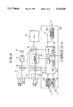
- FIG. 1 illustrates the configuration of an audio-visual system wherein an embodiment of the present invention is employed.
- FIG. 2 illustrates the configuration of a position specification input handling portion of a remote control system of an embodiment of the present invention.
- FIG. 3 illustrates a remote commander having an angular velocity sensor of an embodiment of the present invention.
- FIG. 4 illustrates an angular velocity detecting operation of a remote commander of an embodiment of the present invention.
- FIG. 5 is a flow chart for an angular velocity detecting operation of a remote commander of an embodiment of the present invention.
- FIG. 6 illustrates a remote commander of an embodiment of the present invention.
- FIG. 7 is a flow chart for remote control operations in a first embodiment of the present invention.
- FIG. 8 illustrates display operations of the first embodiment of the present invention.
- FIG. 9 illustrates the manner in which the coordinates of a pointer is managed according to an embodiment of the present invention.
- FIG. 10 illustrates the setting of a certain control area on coordinates.
- FIG. 11 illustrates an example of screen display according to an embodiment of the present invention.
- FIG. 12 illustrates an example of the screen display of a pointer and control pictures according to an embodiment of the present invention.
- FIG. 13 illustrates an example of the screen display of a state wherein a control picture is specified with a pointer according to an embodiment of the present invention.
- FIG. 14 illustrates an example of the display of control pictures wherein a certain control area is set according to an embodiment of the present invention.
- FIG. 15 illustrates an example of screen display wherein a pointer has been moved to the left end of a screen according to an embodiment of the present invention.
- FIG. 16 illustrates an example of the screen display of control pictures for input switching according to an embodiment of the present invention.
- FIG. 17 illustrates an example of the screen display of a pointer and control pictures according to an embodiment of the present invention.
- FIG. 18 illustrates display operations of a second embodiment of the present invention.
- FIG. 19 is a flow chart for remote control operations of the second embodiment of the present invention.
- FIG. 20 illustrates display operations of a third embodiment of the present invention.
- FIG. 21 is a flow chart for remote control operations of the third embodiment of the present invention.
- FIG. 22 illustrates display operations of a fourth embodiment of the present invention
- FIG. 23 illustrates display operations of a fifth embodiment of the present invention.
- FIG. 24 illustrates display operations of a sixth embodiment of the present invention.
- FIG. 25 illustrates the setting of end portions according to the sixth embodiment of the present invention.
- FIG. 26a and FIG. 26b illustrate states of display according to a seventh embodiment of the present invention. Both of FIG. 26a and FIG. 26b show states of the display of mode names for control pictures.
- FIG. 27 illustrates a state 6f display according to an alternative to the seventh embodiment of the present invention.
- FIG. 1 and FIG. 2 show the configuration of a remote control System according the present embodiment.
- FIG. 1 illustrates an audio-visual system wherein the remote control system according to the present invention is employed.
- FIG. 2 is a block diagram for the remote control system.
- reference numeral 10 designates an audio-visual selector amplifier (hereinafter referred to as an AV selector amplifier); 61 designates a video tape recorder (hereinafter referred to as a VTR); 62 designates a compact disk player (hereinafter referred to as a CD player); 63 designates a television tuner (hereinafter referred to as a TV tuner); 64 designates a video disk player (hereinafter referred to as a VDP); 70 designates a monitor device: and 71 designates a speaker.
- an AV selector amplifier designates an audio-visual selector amplifier
- VTR video tape recorder
- CD player compact disk player
- 63 designates a television tuner (hereinafter referred to as a TV tuner)
- 64 designates a video disk player (hereinafter referred to as a VDP)
- 70 designates a monitor device: and 71 designates a speaker.
- Audio-visual signal outputs of the VTR 61, CD player 62, TV tuner 63, and VDP 64 are connected to the AV selector amplifier 10. Connections are provided so that the audio and visual signals selected by the AV selector amplifier 10 are output from the monitor device 70 and the speaker 71.
- the VTR 61, CD player 62, TV tuner 63, and VDP 64 are equipped with infrared receiving portions 61a, 62a, 63a, and 64a, respectively, and can normally be remote-controlled by infrared command signals output by remote commanders to be exclusively used by the respective apparatus. In the present embodiment, however, those apparatus can be controlled with a single remote commander R.
- the remote control system which is the first embodiment of the present invention is constituted by the remote commander R and a position specification input handling portion (illustrated in FIG. 2) incorporated in the AV selector amplifier 10.
- the remote commander R those capable of outputting only the information of position changes on x and y coordinates and "enter" information will be sufficient.
- devices usable as the remote commander R include those having only a shuttle ball S as an operating portion as shown, those capable of outputting position change information obtained by an angular velocity sensor, an acceleration sensor or the like, those capable of outputting rotation information such as mice for personal computers, those capable of outputting the information of the direction in which a joy stick is operated, and those having direction keys for four, eight or other number of directions. Any of infrared, radio, and wire signal transmission systems may be used.
- a remote commander R utilizing a shuttle ball S
- it outputs the information of position changes in x and y directions as, for example, infrared modulation signals when a user rotates the shuttle ball S. It is further adapted to output "enter" information when the shuttle ball S is urged against something.
- FIG. 3 is a block diagram showing the internal configuration of a remote commander R utilizing an angular velocity sensor, and 1 designates an oscillation gyroscope as the angular velocity sensor.
- An oscillation gyroscope is characterized by a Coriolis force produced in a direction normal to the oscillation of a substance when an angular velocity is applied to the substance.
- the Coriolis force F is expressed as follows.
- the angular velocity ⁇ is proportionate to the Coriolis force F and the angular velocity can be detected by detecting the Coriolis force F.
- a driving piezoelectric ceramic element 1a and a detecting piezoelectric ceramic element 1b are mounted to the oscillation gyroscope 1.
- An alternating signal which is the oscillation output of an oscillator 2 is applied to the driving piezoelectric ceramic element 1a.
- the Coriolis force F is applied to the detecting piezoelectric ceramic element 1b to generate a voltage E.
- the very low voltage obtained from the detecting piezoelectric ceramic element 1b is amplified by an amplifier 3 and is supplied to an A-D converter 4 to be converted into digital data.
- Reference numeral 5 designates a control portion constituted by a microcomputer having a CPU 5a, a ROM 5b, and a RAM 5c and the ROM 5b or RAM 5c stores command signals to be transmitted.
- Reference numeral 6 designates a clock generator.
- the ROM 5b stores in advance command signals for remotely controlling at least one of the above-mentioned VTR 61, CD player 62, TV tuner 63, and VDP 64.
- command signals for remotely controlling other apparatus which are not stored in the ROM 5b are registered and stored by a user as in the above-mentioned U.S. Pat. No. 4,623,887.
- the RAM 5c may be a card-type medium incorporating a RAM to provide replaceability.
- Reference numeral 7 designates an enter key which is, for example, provided on the remote commander R as a control key as shown in FIG. 4. The information of operations on the enter key 7 is supplied to the control portion 5.
- control portion 5 In response to the operations on the enter key 7, the control portion 5 reads an enter command from the ROM 5b or RAM 5c and outputs it to a transmission portion 8.
- the control portion 5 reads an up command or down command from the ROM 5b or RAM 5c in accordance with the digital data for the voltage E input by the A-D converter 4 and supplies it to the transmission portion 8.
- the angular velocity ⁇ applied to the oscillation gyroscope 1 and the voltage E produced are proportionate to each other as shown in FIG. 4.
- the control portion 5 can output a command code which depends on the operation performed by the user on the remote commander R by, for example, comparing the input voltage E (digital data) with voltages Va, Vb, Vc, and Vd.
- the control portion 5 determines the command code to be generated, for example, in accordance with the flow chart in FIG. 5
- the enter command is unconditionally generated (F101 and F102). Otherwise, the input voltage E (digital data) is compared with the voltages Va, Vb, Vc, and Vd. If Vc ⁇ E ⁇ Vd, i.e., if the remote commander R is swung upward, the up command is read from the ROM 5b or RAM 5c (F103 and F104). If Va ⁇ E ⁇ Vb, i.e., if the remote commander R is swung downward, the down command is read out (F105 and F106). If the voltage E input to the control portion 5 satisfies Vb ⁇ E ⁇ Vc, no command code is generated. This is to provide a dead zone to prevent any command code from being output when the remote commander R is very lightly touched or carried around by the user.
- a command code thus generated by the control portion 5 is subjected to a predetermined modulation process at the transmission portion 8 and is output to a predetermined apparatus as an infrared signal or radio wave.
- two units of the oscillation gyroscope 1 (1x and 1y) are provided in orthogonal directions as shown in FIG. 6 as movement information (angular velocity) detecting means for the vertical direction x and the horizontal direction y.
- the oscillation gyroscopes 1x and 1y detect the angular velocity ⁇ x at which the remote commander; is swung to the left or right to output a leftward movement command or a rightward movement command (i.e., the information of a position change in x-direction) and detects the angular velocity ⁇ y at which the remote commander R is swung upward or downward to output an up command or a down command (i.e., the information of a position change in y-direction).
- FIG. 2 shows a position specification input handling portion provided in the AV selector amplifier 10 which constitutes the remote control system of the present embodiment by being adapted to the remote commander R which is equipped with the shuttle ball as described above, a track ball, a jog shuttle, x and y angular velocity sensors or the like to be capable of outputting position change information.
- 11 reference numeral input selector portion which selects one input audio signal from among audio signals supplied by the VTR 61, CD player 62, TV tuner 63, and VDP 64 connected as external apparatus.
- the audio signal selected by the audio input selector portion 11 is supplied through a volume adjusting portion 12 to an amplifier 13 to be amplified and is in turn supplied to a speaker 71 connected thereto to be output as a sound.
- Reference numeral 14 video input selector portion which selects one input video signal from among video signals supplied by the VTR 61, CD player 62, and TV tuner 63 connected as external apparatus.
- the video signal selected by the video input selector portion 14 is supplied through a video switching portion 15 to the monitor device 70 connected as a display device and is output as a picture.
- a position specification input handling portion 20 which handles command codes constituting the position specification information (x-y position change information and "enter" information) transmitted by the remote commander R.
- Reference numeral 21 designates a radio wave receiving portion for receiving and demodulating the command codes radio-transmitted by the remote commander R.
- Reference numeral 22 designates an infrared receiving portion for receiving and demodulating the command codes transmitted using infrared rays.
- the remote commander R of the present embodiment will be described as outputting the position specification information as infrared modulation signals.
- Reference numeral 23 designates a control portion constituted by a microcomputer having a CPU 23a, a ROM 23b, and a RAM 23c.
- the control portion 23 performs control functions of various remote control systems in accordance with the operation information of the remote commander R supplied by the infrared receiving portion 22 and it further functions as a control portion for the AV selector amplifier. Specifically, it performs control on the switching operations of the audio input selector portion 11 and the video input selector portion 14, volume control on the volume adjusting portion 11, and control on the switching operations of the video switching portion 15 and the like in accordance with the input of the operations performed by a user.
- Reference numeral 24 designates a panel operation portion on which various control keys are provided. Operation information from the panel operation portion 24 are supplied to the control portion 23.
- the panel operation portion 24 is provided with a function switching key for causing the control portion 23 to control the switching operations of the audio input selector 14, a video switching key for controlling the switching operations of the video switching portion 15, a volume control key, and the like.
- Reference numeral 25 designates a graphic controller which generates predetermined character picture signals in accordance with instructions from the controller 23.
- a character picture signal is, for example, superimposed on a video signal selected by the video input selector portion 14 and is supplied through the video switching portion 15 to a CRT display portion 16.
- control pictures SD indicating the control of various apparatus and the picture of a finger or an arrow (hereinafter referred to as pointer P) for selecting a indicating a certain control picture SD from among control the various pictures SD displayed on the CRT.
- pointer P arrow
- a plurality of control pictures SD are displayed on one screen but the control pictures SD displayed are divided into groups each associated with an apparatus.
- control pictures SD for reproduction, picture recording, stopping, fast-forwarding, rewinding and the like are set as the group of control pictures SD for the VTR 61 and they are simultaneously displayed.
- the pointer P as the position specification picture may be substituted by a cursor, a frame moving about control pictures, or a system wherein only the specified control picture changes its color.
- the ROM 23b or the RAM 23c of the control portion 23 stores control data for the above mentioned portions performing the functions of the AV selector amplifier and various command codes for the electronic apparatus such as the VTR 61 connected to the AV selector amplifier and other external electronic apparatus bearing no relation to the AV selector amplifier at all.
- the command code is read out and supplied to the infrared transmission portion 26.
- the read command code is also supplied to a terminal 27 which in turn supplies it to a predetermined external apparatus or an internal circuit system through wire-transmission. If a system bus line is established between the apparatus, the command may be transmitted over the bus.
- the infrared transmission portion 26 performs a predetermined modulation process on the command code thus supplied and transmits it to the outside as an infrared signal.
- the infrared transmission portion 26 is provided, for example, as a non-directional infrared output unit as shown in FIG. 1. Therefore, an infrared signal output by the infrared transmission portion 26 can be received by an infrared receiving portion of each of the electronic apparatus such as the VTR 61 disposed around the AV selector amplifier.
- a radio-type command code transmission portion may be provided instead of or in combination with the infrared transmission portion.
- FIG. 7 is a flow chart showing the process performed by the control portion 32 in accordance with the position specification information (x-y position change information and "enter" information) transmitted by the remote commander R.
- FIG. 8 conceptually shows the switching of display between the control pictures SD for controlling various apparatus.
- the ROM 23b or ROM 23c stores command codes for performing various operations on various apparatus.
- the corresponding control pictures are divided into groups each associated with one of the apparatus.
- the monitor device 70 switchably displays various control pictures corresponding to various command codes such as reproduction, stop, and picture recording command codes to VTR 61, various control pictures corresponding to various command codes such as reproduction and stop command codes to the CD player 62, various control pictures corresponding to command codes such as a channel switch command code to the TV tuner 63.
- various control pictures corresponding to various command codes such as reproduction and stop command codes to the VDP 64, and various control pictures corresponding to various command codes such as input switching and volume command codes to the AV selector amplifier.
- control on the apparatus currently selected by the AV selector amplifier 10 as the input can be easily performed.
- the group of control pictures SD associated with the apparatus currently selected as the input are displayed.
- the control pictures SD associated with the operations of the VTR are displayed.
- the pointer P is moved in accordance with x-y position change information from the remote commander R until it points to a certain control picture SD, e.g., "VTR reproduction” where the "enter" command is supplied from the remote commander R.
- a command code "VTR reproduction” corresponding to the control picture entered is read from the ROM 23b or the RAM 23c and is output from the infrared transmission portion 26.
- the group of control pictures SD is switched to a group of control pictures SD for an input switching operation to are then displayed to allow the input switching operation to be performed. Further, when the pointer P enters a certain area on the screen, certain control pictures are displayed to allow associated control to be performed.
- the AV selector amplifier 10 has initially selected the VTR 61 as the input and a reproduction signal from the VTR 61 has been supplied to the monitor device 70 as a video signal to display the picture shown in FIG. 11.
- the control portion 23 controls the video switching portion 15 so that switching from 2a terminal Tt to a terminal Tg takes place. Consequently, as the output of the graphic controller 25, a picture signal from the video input selector portion 14 along with a predetermined character picture superimposed thereon is supplied to the monitor device 70 and, for example, the pointer P and the control pictures SD associated with the R 61 are displayed as shown in FIG. 12.
- the control portion 23 resets a timer to start time measurement (F204) and causes the control pictures SD associated with the apparatus currently selected as the input to be displayed (F206). Specifically, it instructs the graphic controller 25 of the data to be displayed.
- the measurement of time at step F204 is for erasing the control pictures SD and the pointer P when they are not necessary, According to this time measurement, the control pictures SD and the pointer P are erased if no command is transmitted for a predetermined period of time after the command most recently transmitted from the remote commander R (F202 and F203). In other words, this is a process to avoid complication due to the control pictures SD and pointer P remaining on the screen unecessarily.
- control pictures for causing the VTR 61 to perform operations are displayed as the control pictures SD on the screen of the monitor device 70 as shown in FIG. 12.
- the control portion 23 transmits a "VTR fast-forward" command signal.
- This causes the infrared transmission portion 26 to output a transmission signal in accordance with the "VTR fast-forward" command signal which is received by the infrared receiving portion 61a of the VTR 61.
- the VTR 61 thus performs fast-forwarding.
- the pointer P is moved on the screen accordingly. Specifically, a new position for the pointer P is calculated (F209) and data are sent to the graphic controller 25 so that the pointer P is moved to the position calculated on the screen, realizing the movement on the display (F210).
- the CPU 32a includes an x-y coordinate system corresponding to the screen of the monitor device 70. This allows determination of the position and action of the pointer P and its relationship to the control pictures SD.
- a coordinate system having 255 dots in the x-direction and 192 dots in the y-direction is constructed as shown in FIG. 9 in correspondence to the display screen and a position P 0 for the pointer P is recognized as a value on the coordinate system.
- the coordinate value for the current position P 0 of the pointer P is added with the x-y position change information to calculate a new position for the pointer P.
- the control picture SD whose position on the display coincides with the position of the pointer P is selected and the corresponding command is transmitted. According to this process, since the position in which each control picture SD is displayed is also recognized as a numerical value indicating an area on the x-y coordinate system in the CPU 23a, the selected control picture can be determined from the correspondence between those values on the coordinate system.
- step F212 determines whether the pointer P is, for example, in the range indicated as the area A in the x-y coordinate system in FIG. 10.
- the area A is set as an area wherein 200 ⁇ x ⁇ 245 and 0 ⁇ y ⁇ 150.
- step F212 the process proceeds from step F212 to step F214 to display the group of control pictures SD for volume adjustment as shown in FIG. 14.
- the control pictures indicating the operations of turning up and down the volume and muting are displayed on the monitor device 70.
- control portion 23 transmits a "volume up" control signal to the volume adjusting portion 12.
- the process proceeds from F212 to F213 to erase any volume control picture displayed (if no volume control picture is displayed, no process takes place) and returns to step F201.
- the volume control pictures are erased and the display returns to, for example, the state as shown in FIG. 12.
- a special control area is set as described above. Operability can be significantly improved by causing the control pictures to be automatically displayed to be operable at the point in time when the pointer P enters the control area.
- the x-coordinate value of the pointer P is changed from 0 to 254 so that the pointer P appears at the right end of the screen for input switching (F216).
- step F205 the process proceeds from step F205 to step F217.
- the contents of the command is determined (F217). If it is x-y position change information, a new pointer position is calculated on the x-y coordinate system accordingly as previously described (F218) and the pointer P is moved to the new pointer position on the screen (F219). Then, it is determined whether the position of the pointer P on the x -coordinate equals 255 and, if not, the process proceeds to step F201 without any further action.
- the screen for controlling input switching currently displayed is erased and the display is switched to the initial state, i.e,, the state as shown in FIG. 15 wherein the control pictures SD for the apparatus currently selected as the input are displayed (F221).
- the value of x for the pointer position at this time is set to 1 so that the pointer P appears in the vicinity of the left end of the screen (F222). It appears to the user operating the remote commander R that the initial screen appears as the right page side of the screen as the pointer P is moved fully to the right on the screen.
- the control portion 23 performs the process at step F223 to output the command signal for input switching. Specifically, it controls the audio input selector portion 11 and the video input selector portion 14 so that they select the input terminals for the VDP.
- control pictures for controlling input switching are erased and the group of control pictures for the apparatus selected are displayed. In this case, therefore, the control pictures SD for the VDP 64 are displayed as shown in FIG. 17.
- the display for control is switched as conceptually shown in FIG. 8 and the user can control each apparatus by operating the remote commander R.
- the user can control various apparatus only by operating the remote commander R to move the pointer P and by performing the enter operation in desired positions with his or her eyes on the screen of the monitor device 70.
- the remote commander R can be very easily operated. As a result, it is possible to avoid complication in operation due to a number of keys and inconvenience that the user has to turn his or her eyes from the monitor screen.
- control pictures for input switching can be called up by moving the pointer P fully to the left, which operation feels like turning a page of a book.
- the initial control pictures can be called up by moving the pointer P fully to the right on the screen for the input switching, which operation feels like replacing the page.
- the end portions of two screens where those screens are called up each other are positioned opposite to each other.
- control pictures for the VTR or the like are displayed, the control pictures for input switching are called up at the left end of the screen while in the mode wherein the control pictures for input switching is displayed, control pictures for the VTR or the like are called up at the right end of the screen which is opposite to the above-described left end of the screen.
- FIG. 18 and FIG. 19 A second embodiment of the present invention will now be described with reference to FIG. 18 and FIG. 19.
- This remote control system has the same configuration as that shown in FIG. 1 and FIG. 2 and the description of the same will therefore be omitted.
- FIG. 19 is a flow chart showing the process performed by the control portion 23 in accordance with position specification information (x-y position change information and "enter") transmitted by the remote commander R.
- FIG. 18 conceptually shows the operations of switching the display of control pictures SD for controlling various apparatus.
- the shaded areas represent a portion where the control pictures for those apparatus are displayed.
- the areas enclosed by the dotted lines represents an area wherein control pictures for volume control are displayed (they correspond to the area A in FIG. 10).
- the switching between the display of the control pictures for the apparatus currently selected as the input and the display of the control pictures for input switching is performed in a manner that feels like turning a page of a book.
- the switching between the groups of control pictures for the respective apparatus takes place according to the relationships as represented by the moving directions of the pointer as indicated by the arrows in solid lines in FIG. 18.
- the switching of display takes place to show the control pictures for the VTR, the control pictures for the VDP, the control pictures for the TV tuner, and the control pictures for the CD player in the order listed each time the pointer P is moved fully to the right.
- the switching of display takes place to show the control pictures for the TV tuner, the control pictures for the VDP, the control pictures for the VTR, and the control pictures for input switching in the order listed each time the pointer P is moved fully to the left.
- FIG. 18 illustrates this situation as a virtual positional relationship.
- volume control in a mode wherein control pictures other than those for input switching are displayed, the control pictures for volume adjustment are displayed as the pointer P enters the area A shown in FIG. 10 to improve volume-controllability.
- control portion 23 Upon the input of any command code (F301) from the remote commander R, the control portion 23 resets the timer to start time measurement (F304) and, thereafter, determines whether the control pictures for input switching are currently displayed (F305).
- the resetting and starting of the timer at step F304 are for erasing the control pictures SD and the pointer P when they are not necessary as in the first embodiment.
- the control pictures SD and the pointer P are erased if no command is transmitted for a predetermined period of time after the command most recently transmitted from the remote commander R (F302 and F303). This is a process to avoid complication due to the control pictures SD and pointer P remaining on the screen unnecessarily.
- control pictures for input switching are not displayed, it is determined, for example, whether the display is in a state wherein no control picture is displayed as shown in FIG. 11 (F306). If the state of the display is as shown in FIG. 11, it is determined what is currently selected by the audio input selector portion 11 and the video input selector portion 14 (F307) and the process step to follow is decided depending on the status of input selection.
- the process proceeds to step F309 if the VTR 61 has been selected as the input, to step F321 if the VDP 64 has been selected, to step F331 if the TV tuner 63 has been selected, and to step F331 if the CD player 62 has been selected.
- the monitor device 70 displays the group of control pictures for the VTR 61 (F309), the group of control pictures for the VDP 64 (F321), the group of control pictures for the TV tuner 63 (F331), or the group of control pictures for the CD player 62 (F341).
- step F306 If any group of control pictures have already been displayed at step F306, depending on the group displayed, the process proceeds to step F310 if the control pictures for the VTR are displayed, to step, F322 if the control pictures for the VDP are displayed, to step F332 if the control pictures for the TV tuner are displayed, and to step F342 if the control pictures of the CD player are displayed.
- steps F310, F322, F332, and F342 determines the contents of commands. If a command is determined to be the "enter" command, the process proceeds from any of those steps to step F348 at which the command signal for the control pictures pointed by the pointer P when the "enter" command is input is read from a ROM 32b or RAM 32c to be transmitted from the infrared transmission portion 26 or the like.
- steps F310, F322, F332, and F342 of the respective modes wherein the respective groups are displayed determines the contents of a command as x-y position change information
- a pointer moving process is entered. Specifically, a new pointer position is calculated on the coordinate system (F312, F323, F333, and F343). The calculated pointer position is transmitted to the graphic controller 25 to move the pointer P on the screen (F313, F324, F334, and F344).
- the control pictures for volume control are displayed as shown in FIG. 14 (F357 and F358) enabling volume control. If the pointer is out of the area A, the control pictures for volume control are not displayed (erased) (F357 and F318).
- step F305 When the pointer has been moved fully to the left on the screen on which the control pictures for the VTR had been displayed as described above and the screen for input switching thus called up are currently displayed, the process proceeds from step F305 to F349 upon the input of a command code (F301). Then, the contents of the command is determined (F349). If it is x-y position change information, a new pointer position is calculated on the x-y coordinate system accordingly (F352) and the pointer P is moved to the new pointer position on the screen (F353). Then, it is determined whether the position of the pointer P on the x-coordinate equals 255 (F354) and, if not, the process returns to step F301 without any further action.
- step F354 When the pointer is moved to reach the position on x-coordinate which equals 255 at step F354, i.e., when the pointer P is moved fully to the right end of the screen for controlling input switching, the screen for controlling input switching currently displayed is erased and the control pictures SD for VTR are displayed (F355).
- the value of x for the pointer position at this time is set to 1 so that the pointer P appears in the vicinity of the left end of the screen showing the control pictures SD for the VTR (F356). It appears to the user that the screen for controlling the VTR is on the right page side of the screen for the input switching.
- step F350 the control portion 23 outputs the command signal for input switching to the audio input selector portion 11 and the video input selector portion 14 so that the apparatus pointed by the pointer P at this point in time is selected as the input.
- control pictures for controlling input switching are erased and the group of control pictures for the apparatus selected are displayed as in the first embodiment (F351).
- the pointer P when the pointer P is moved to the left end of the screen, i,e, when the x-coordinate value of the pointer equals 0 with the control pictures for the CD player displayed, the control pictures for the CD player which have been displayed are erased and the control pictures for the TV tuner are displayed (F345 and F346).
- the x-coordinate value of the pointer P is changed from 0 to 254 so that the pointer P appears at the right end of the screen showing the control pictures for the TV tuner (F347).
- the display for control is switched as conceptually shown in FIG. 18 and the user can control each apparatus by operating the remote commander R.
- the control screen for each apparatus can be called up by moving the pointer P fully to the left or right end, which operation feels like turning a page of a book.
- the ends of two virtually adjoining screens where the calling up of each other is performed are set in opposite positions on the screen and the previous screen can be called up in a manner that feels like turning a page of a book. This makes the operation easy to understand and eliminates the need for the "enter" operation or the like in switching the screens, thereby significantly improving operability.
- a third embodiment of the present invention will now be described with reference to FIG. 20 and FIG. 21.
- the remote control system of the present embodiment also has the same configuration as that shown in FIG. 1 and FIG. 2 and the description of the same will therefore be omitted.
- FIG. 21 is a flow chart showing the process performed by the control portion 23 in accordance with position specification information (x-y position change information and "enter") transmitted by the remote commander R.
- FIG. 20 conceptually shows operations Of switching the display of control pictures SD for controlling various apparatus.
- the shaded areas represent a portion where the control pictures for those apparatus are displayed.
- the switching of display takes place between the groups of control pictures for the apparatus when the pointer is moved to the left or right.
- the switching takes place when the pointer is moved to the left or right or upward or downward.
- control pictures for the TV tuner are displayed as shown in FIG. 20
- the control pictures for input switching appear if the pointer P is moved fully to the right: the control pictures for the VTR appear if the pointer P is moved fully to the left: the control pictures for the VDP appear if the pointer P is moved fully upward: and the control pictures for the CD player appear if the pointer P is moved fully downward.
- control pictures for input switching are treated similarly to the control pictures for the apparatus. That is, the switching to the control pictures for input switching is not performed.
- volume control in any mode wherein control pictures are displayed, the control pictures for volume adjustment are displayed as the pointer P enters the area A shown in FIG. 10 to improve volume-controllability.
- control portion 23 Upon the input of any command code (F401) from the remote commander R, the control portion 23 resets the timer to start time measurement (F404) and, thereafter, determines whether the control pictures for input switching are currently displayed (F405).
- control pictures for input switching are not displayed, it is determined whether the display is in a state wherein no control picture is displayed as shown in FIG. 11 (F406). If the state of display is as shown in FIG. 11, it is determined what is currently selected by the audio input selector portion 11 and the video input selector portion 14 (F407) and the process step to follow is decided depending on the status of input selection.
- the process proceeds to step F409 if the TV tuner 63 has been elected as the input, to step F428 if the VTR 61 has been selected, to step F435 if the VDP 64 has been selected, and to step F442 if the CD player 62 has been selected.
- the monitor device 70 displays the group of control pictures for the TV tuner 63 (F409), the group of control pictures for the VTR 61 (F428), the group of control pictures for the VDP 64 (F435), or the group of control pictures for the CD player 62 (F442).
- step F406 If any group of control pictures have already been displayed at step F406, depending on the group displayed, the process proceeds to step F410 if the control pictures for the TV tuner are displayed, to step F429 if the control pictures for the VTR are displayed, to step F436 if the control pictures for the VDP are displayed, and to the step F443 if the control pictures for he CD player are displayed.
- step F405 If a command code is input from the remote commander R in the mode wherein the control pictures for input switching are displayed, the process proceeds from step F405 to F449.
- steps F410, F429, 436, F443 and F449 determines the contents of commands. If a command is determined to be the "enter" command, the process proceeds from any of those steps to step F450 at which the command signal for the control pictures printed by the pointer P when the "enter" command is input is read from a ROM 32b or RAM 32c to be transmitted from the infrared transmission portion 26 or the like.
- steps F410, F429, 436, F443 and F449 of the respective modes wherein the respective groups are displayed determines the contents of a command as x-y position change information
- a pointer moving process is entered. Specifically, a new pointer position is calculated on the coordinate system (F411, F430, F437, F444 and F451). The calculated pointer position is transmitted to the graphic controller 25 to move the pointer p on the screen (F412, F431, F438, F445 and F452 ).
- any mode wherein a group of control pictures are displayed if the pointer P enters the area A shown in FIG. 10 as a result of the movement of the pointer P, the control pictures for volume control are displayed as shown in FIG. 14 (F417 and F418) enabling volume control. If the pointer is out of the area A, the control pictures for volume control are not displayed (erased) (F417 and F419).
- the control pictures for the TV tuner which have been displayed are erased and the control pictures for the VTR are displayed (F414 and F422).
- the x-coordinate value of the pointer P is changed from 255 to 1 so that the pointer p appears at the left end of the screen on which control on the VTR can be performed (F421). In other words, it appears to the user that the control pictures for the VTR appear at the right page side of the screen for the TV tuner.
- the control pictures for the TV tuner which have been displayed are erased and the control pictures for the VDP are displayed (F415 and F424).
- the y-coordinate value of the pointer p is changed from 0 to 191 so that the pointer P appears at the lower end of the screen on which control on the VDP can be performed (F425). In other words, it appears to the user that the control pictures for the VDP appear at the upper side of the screen for the TV tuner.
- the control pictures for the TV tuner which have been displayed are erased and the control pictures for the CD player are displayed (F416 and F426).
- the y-coordinate value of the pointer P is changed from 192 to 1 so that the pointer P appears at the upper end of the screen on which control on the CD player can be performed (F427). In other words, it appears to the user that the control pictures for the CD player appear at the lower side of the screen for the TV tuner.
- the control pictures for the VDP When the control pictures for the VDP are displayed, it is detected whether the pointer P has reached the lower end of the screen or not (F439).
- the y-coordinate value of the pointer equals 192 at which value the pointer is at the lower end of the screen, the control pictures for the VDP which have been displayed are erased and the control pictures for the TV tuner are displayed (F439 and F440).
- the y-coordinate value of the pointer P is changed from 192 to 1 so that the pointer P appears at the upper end of the screen showing the control pictures for the TV tuner (F441).
- the display for control is switched as conceptually shown in FIG. 20 and the user car control each apparatus by operating the remote commander R.
- the control screen for each apparatus can be called up by moving the pointer P fully to the left or right or upward or downward, which operation feels like turning a page of a book.
- FIG. 22 conceptually shows a fourth embodiment of the present invention which can be regarded as a modification of the second embodiment (The shaded areas represent states wherein the control pictures for the respective apparatus are displayed. This applies to FIG. 23 and FIG. 24.).
- the display is sequentially switched to the control pictures for the VTR, the control pictures for the VDP, the control pictures for the TV tuner, and the control pictures for the CD player each time the pointer P is moved fully to the right. Further, if the pointer is moved fully to the right in the mode wherein the screen displays the control pictures for the CD player, the switching takes place in a circulating manner by returning the display mode to the display of the control pictures for input switching.
- FIG. 23 conceptually shows a fifth embodiment of the present invention. As illustrated, a virtual positional relationship is maintained between the groups of control pictures. In the fifth embodiment, if the pointer is moved fully in the direction of the arrow shown in the screen showing each group of control pictures, another group of control pictures are called up.
- control portion 23 may be adapted to control the switching of pictures by detecting that the pointer reaches upper, lower, left or right end of the screen with reference to the x and y values of the position of the pointer.
- FIG. 24 conceptually shows a sixth embodiment of the present invention.
- the side of a screen corresponding to an end of the area wherein pictures are displayed is set, in its entirety, as an area for calling up the next pictures.
- an end of a screen is divided into several areas so that more pictures can be called up.
- the state wherein the control pictures for the TV tuner (the control pictures for channel, volume, and the like) are displayed, is regarded as a reference mode.
- the control portion 23 recognizes the upper, left and right ends of a screen as six divisions on the x-y coordinate system as shown in FIG. 25.
- the control pictures associated with the end portions T 1 . T 2 , T 3 , T 4 , T 5 , and T 6 to be called up are the control pictures for input switching, control pictures for a first VTR, control pictures for a second VTR, the control pictures for the VDP, control pictures for a BS tuner, and the control pictures for the CD player, respectively. Specifically, when the pointer P reaches any one of the end portions T 1 through T 6 , the associated control pictures are displayed instead of the control pictures for the TV tuner.
- An end portion is set for calling up the control pictures for the TV tuner from the control pictures called up at the end portions T 1 through T 6 so that directional relationships are established between the control pictures called up at the end portions T 1 through T 6 and the control pictures for the TV tuner.
- the present embodiment it is possible to call up a plurality of groups of control pictures from one picture mode by dividing the ends of the screen.
- the directions in which the screen modes are called up can be correlated, i.e. the ends at which the screens are switched are set substantially opposite to each other, and operability is thus improved.
- control pictures e.g., control pictures for timed picture recording
- the control pictures are thus organized into a virtual hierarchical structure and the switching of the control pictures takes place between basic operations as a first hierarchical level and complicated operations and operations such as adjustment as second and third hierarchical levels. This allows more diverse operations without adversely affecting operability.
- the end portions may be divided at the second and third hierarchical levels.
- FIG. 26a and FIG. 26b illustrate a seventh embodiment of the present invention.
- the seventh embodiment is preferably combined with, for example, the sixth embodiment. According to the present embodiment, in a control picture display mode, other groups of control pictures which are called up at the ends of the screen are displayed.
- control picture mode names N e.g., "input switching", "VTR 1", “VTR 2", “VDP”, "BS tuner”, and “CD" are displayed at the respective end portions T 1 through T 6 set as shown in FIG. 26a.
- control picture mode names N e.g., "timed picture recording” and "TV operation” are displayed at the left end and right end, respectively, of the screen.
- Such display prevents the screen switching from becoming difficult even if the virtual screen arrangement becomes complicated and the number of screens is increased. It goes without saying that such display is effective as a guidance for operations even when the number of the screens switched is small as in the first embodiment.
- guidance can be displayed for a screen which is called up from the screen by way of one or a plurality of screens.
- the complication of operations can be avoided by guiding the (virtual) direction in which the desired screen can be called up from the screen currently displayed.
- the remote control system is not limited thereto and may of course be implemented in various other ways.
- the apparatus controlled may include a multi-disk player capable of reproducing a plurality of kinds of optical disks instead of the VDP 64.
- the objects to be controlled may include electronic apparatus such as an air conditioner which have no relationship with the AV selector amplifier 10. If it is desirable to add some apparatus to be controlled, such a demand can be satisfied by causing the remote control system to learn the command codes for such, storing them in the RAM 23c and adding the control pictures SD at the same time.
- the remote control system according to the present invention may be incorporated in a device other than the AV selector amplifier or may be formed alone.
- control pictures for volume control are displayed when the pointer enters a preset control area in the embodiments.
- this method may also be employed for control display for channel switching. This is preferable especially for operations which are likely to be frequently performed.
- the position and size of a control area to be set can be varied.
Abstract
A remote control system comprises an audio apparatus audio signal, a video apparatus, a remote input device, a selector, and an output device wherein the remote input device transmits a position specification signal to the selector. The selector is connected to the audio and video apparatus and receives the position specification signal from the remote input device. The memory portion stores picture data include mode setting data for setting operation modes of the audio and video apparatus, command codes associated with the operation modes, and selection picture data for selecting the audio apparatus or Video apparatus. When the control portion detects that the position specification signal input by the remote input device indicates a predetermined position, it reads picture data in accordance with the input position specification signal from the memory portion. The command generation portion then selectively supplies a command code to the audio apparatus or video apparatus in accordance with the input position specification signal. The output device has a display portion to which the picture data read by the control portion from the memory portion are supplied, and the output signal of either the audio apparatus or video apparatus selected by the selector is supplied to the output device. When the control portion of the selector detects that the position specification signal input by the remote input device is a signal indicating the position corresponding to any one of the four sides of the display portion with the picture data of either the audio apparatus or video apparatus displayed on the display device, either the picture data associated with the other apparatus or the selection picture data are read from the memory portion and are displayed on said display portion.
Description
1. Field of the Invention
The present invention relates to a remote control system and the control method thereof and, more particularly, to a remote control system for performing remote control with reference to a display screen and the control method thereof.
2. Description of the Related Art
It has recently become possible to perform remote control of audio-visual apparatus such as VTR's, television receivers and compact disk players as well as various electronic apparatus such as air conditioners and lighting apparatus using a remote commander.
It is inconvenient for a use to have remote commanders to be exclusively used for respective apparatus. In order solve this, some remote commanders are provided with a learning function to store various command codes so that a single remote commander can control several kinds of electronic apparatus. For example, refer to U.S. Pat. No. 4,623,887.
However, as the contents of control become diverse as a result of the improvements in the functions of apparatus, remote commanders must have more control keys. In addition, if the learning function is employed, the number of control keys required is further increased so that a plurality of apparatus can be handled. Thus, remote commanders have been provided with a number of control keys, which have resulted in a problem that operations have become difficult, instead, because of reasons such as the difficulty in finding the control keys to be pushed to perform a certain operation.
Further, one must operate control keys while looking at the remote commander in operation in order to distinguish many control keys on it. This has been inconvenient because, for example, it has been difficult to operate a remote commander without looking at it while watching a television screen instead.
It is, therefore, an object of the present invention to provide a remote control system which resolves the above-mentioned problems.
It is another object of the present invention to provide a control method for a remote control system which resolves the above-mentioned problems.
According to the present invention, there is provided a remote control system including an operation input device, a receiver, a memory, a display controller, a command generator, and a transmitter. The operation input device outputs position specification information through line or radio transmission in response to operations. The receiver receives the position specification information transmitted by the operation input device. The memory stores various command codes which are divided into a plurality of groups. The display controller displays control pictures corresponding to the command codes stored in the memory on a group basis according to the position specification information received by the receiver while displays a position specification picture indicating one of the control pictures displayed. The command generator reads the command code corresponding to the control picture specified by the position specification picture according to the position specification information received by the receiver from the memory and outputs the same. The receiver transmits the command code output by the command generator to an apparatus or portion to be controlled on through line or radio transmission. When the position specification picture is moved to an end area which is set to be a part or the whole of the end portion surrounding the pictures on the display screen according to the position specification information received by the receiver while a group of control pictures are displayed, the display controller switches the display of the control pictures to a predetermined group of control pictures which are different from the group of control pictures being currently displayed.
According to the present invention, there is provided a control method for a remote control system. The remote control system controlled in accordance with the control method comprises a remote input device for transmitting a position specification signal, a memory for storing a plurality of picture data constituted by a plurality of mode setting data for setting the operation modes of a plurality of apparatus to be controlled and a plurality of command codes corresponding the picture data, and a controller which is supplied with the position specification signal from a remote control means and which reads the picture data corresponding to the position specification signal supplied from the memory, displays the picture data on a display means and reads the command code corresponding to the position specification signal supplied from the memory and supplies it to an apparatus to be controlled. According to this control method, with picture data read from the memory displayed on the display, the controller reads a command code from the memory in accordance with the position specification signal corresponding to mode setting data input by the remote input device and supplies it to an apparatus to be controlled; when the controller detects that the position specification signal input from the remote input device is a signal corresponding to a predetermined position, it reads the picture data corresponding to the position specification signal input from the remote input device from the memory, displays the picture data newly read from the memory instead of the picture data currently displayed on the display device, and supplies the command code to a plurality of apparatus.
The present invention makes it possible to obtain a remote control system having very high operability. According to the present invention, the number of control keys on a remote commander as a remote input device can be greatly reduced and it is possible to switch the operations of a plurality of apparatus or a plurality of kinds of apparatus. As a result, operations to be performed by a user can be simplified making him or her free from mistakes in operating keys on the remote commander or complications in operation. Further, since operations can be performed using a remote commander with one's eyes on a display portion as an output device, it is not necessary to confirm the keys on the remote commander for each operation and operability is thus improved. To switch the control picture corresponding to an apparatus to be controlled displayed on the display portion, it is necessary only to move the position specification signal from the remote commander indicated by a pointer or the like on the display portion to an end of the display portion. This makes operations easy to understand and carry out.
FIG. 1 illustrates the configuration of an audio-visual system wherein an embodiment of the present invention is employed.
FIG. 2 illustrates the configuration of a position specification input handling portion of a remote control system of an embodiment of the present invention.
FIG. 3 illustrates a remote commander having an angular velocity sensor of an embodiment of the present invention.
FIG. 4 illustrates an angular velocity detecting operation of a remote commander of an embodiment of the present invention.
FIG. 5 is a flow chart for an angular velocity detecting operation of a remote commander of an embodiment of the present invention.
FIG. 6 illustrates a remote commander of an embodiment of the present invention.
FIG. 7 is a flow chart for remote control operations in a first embodiment of the present invention.
FIG. 8 illustrates display operations of the first embodiment of the present invention.
FIG. 9 illustrates the manner in which the coordinates of a pointer is managed according to an embodiment of the present invention.
FIG. 10 illustrates the setting of a certain control area on coordinates.
FIG. 11 illustrates an example of screen display according to an embodiment of the present invention.
FIG. 12 illustrates an example of the screen display of a pointer and control pictures according to an embodiment of the present invention.
FIG. 13 illustrates an example of the screen display of a state wherein a control picture is specified with a pointer according to an embodiment of the present invention.
FIG. 14 illustrates an example of the display of control pictures wherein a certain control area is set according to an embodiment of the present invention.
FIG. 15 illustrates an example of screen display wherein a pointer has been moved to the left end of a screen according to an embodiment of the present invention.
FIG. 16 illustrates an example of the screen display of control pictures for input switching according to an embodiment of the present invention.
FIG. 17 illustrates an example of the screen display of a pointer and control pictures according to an embodiment of the present invention.
FIG. 18 illustrates display operations of a second embodiment of the present invention.
FIG. 19 is a flow chart for remote control operations of the second embodiment of the present invention.
FIG. 20 illustrates display operations of a third embodiment of the present invention.
FIG. 21 is a flow chart for remote control operations of the third embodiment of the present invention.
FIG. 22 illustrates display operations of a fourth embodiment of the present invention,
FIG. 23 illustrates display operations of a fifth embodiment of the present invention.
FIG. 24 illustrates display operations of a sixth embodiment of the present invention.
FIG. 25 illustrates the setting of end portions according to the sixth embodiment of the present invention.
FIG. 26a and FIG. 26b illustrate states of display according to a seventh embodiment of the present invention. Both of FIG. 26a and FIG. 26b show states of the display of mode names for control pictures.
FIG. 27 illustrates a state 6f display according to an alternative to the seventh embodiment of the present invention.
Remote control systems according to the present invention will now be described in detail with reference to the accompanying drawings.
A first embodiment of the present invention will be described.
FIG. 1 and FIG. 2 show the configuration of a remote control System according the present embodiment. FIG. 1 illustrates an audio-visual system wherein the remote control system according to the present invention is employed. FIG. 2 is a block diagram for the remote control system.
In FIG. 1, reference numeral 10 designates an audio-visual selector amplifier (hereinafter referred to as an AV selector amplifier); 61 designates a video tape recorder (hereinafter referred to as a VTR); 62 designates a compact disk player (hereinafter referred to as a CD player); 63 designates a television tuner (hereinafter referred to as a TV tuner); 64 designates a video disk player (hereinafter referred to as a VDP); 70 designates a monitor device: and 71 designates a speaker.
Audio-visual signal outputs of the VTR 61, CD player 62, TV tuner 63, and VDP 64 are connected to the AV selector amplifier 10. Connections are provided so that the audio and visual signals selected by the AV selector amplifier 10 are output from the monitor device 70 and the speaker 71. The VTR 61, CD player 62, TV tuner 63, and VDP 64 are equipped with infrared receiving portions 61a, 62a, 63a, and 64a, respectively, and can normally be remote-controlled by infrared command signals output by remote commanders to be exclusively used by the respective apparatus. In the present embodiment, however, those apparatus can be controlled with a single remote commander R.
The remote control system which is the first embodiment of the present invention is constituted by the remote commander R and a position specification input handling portion (illustrated in FIG. 2) incorporated in the AV selector amplifier 10. As the remote commander R, those capable of outputting only the information of position changes on x and y coordinates and "enter" information will be sufficient. Further, devices usable as the remote commander R include those having only a shuttle ball S as an operating portion as shown, those capable of outputting position change information obtained by an angular velocity sensor, an acceleration sensor or the like, those capable of outputting rotation information such as mice for personal computers, those capable of outputting the information of the direction in which a joy stick is operated, and those having direction keys for four, eight or other number of directions. Any of infrared, radio, and wire signal transmission systems may be used.
For example, in the case of a remote commander R utilizing a shuttle ball S, it outputs the information of position changes in x and y directions as, for example, infrared modulation signals when a user rotates the shuttle ball S. It is further adapted to output "enter" information when the shuttle ball S is urged against something.
A remote commander R utilizing an angular velocity sensor has a configuration, for example, as illustrated in FIG. 3 through FIG. 6. FIG. 3 is a block diagram showing the internal configuration of a remote commander R utilizing an angular velocity sensor, and 1 designates an oscillation gyroscope as the angular velocity sensor.
An oscillation gyroscope is characterized by a Coriolis force produced in a direction normal to the oscillation of a substance when an angular velocity is applied to the substance. The Coriolis force F is expressed as follows.
F=2mvω
where m, v and ω represent mass, velocity and angular velocity, respectively. Therefore, the angular velocity ω is proportionate to the Coriolis force F and the angular velocity can be detected by detecting the Coriolis force F.
A driving piezoelectric ceramic element 1a and a detecting piezoelectric ceramic element 1b are mounted to the oscillation gyroscope 1. An alternating signal which is the oscillation output of an oscillator 2 is applied to the driving piezoelectric ceramic element 1a. When the oscillation gyroscope 1 is rotated in an Ω0 direction in this state, the Coriolis force F is applied to the detecting piezoelectric ceramic element 1b to generate a voltage E.
The very low voltage obtained from the detecting piezoelectric ceramic element 1b is amplified by an amplifier 3 and is supplied to an A-D converter 4 to be converted into digital data.
In response to the operations on the enter key 7, the control portion 5 reads an enter command from the ROM 5b or RAM 5c and outputs it to a transmission portion 8.
The control portion 5 reads an up command or down command from the ROM 5b or RAM 5c in accordance with the digital data for the voltage E input by the A-D converter 4 and supplies it to the transmission portion 8. The angular velocity ω applied to the oscillation gyroscope 1 and the voltage E produced are proportionate to each other as shown in FIG. 4. The control portion 5 can output a command code which depends on the operation performed by the user on the remote commander R by, for example, comparing the input voltage E (digital data) with voltages Va, Vb, Vc, and Vd.
For example, suppose that the oscillation gyroscope 1 is disposed in the remote commander R so that the voltage E is increased due to the angular velocity at which the remote commander R is swung upward and the voltage E is decreased due to the angular velocity at which it is swung downward. Then, the control portion 5 determines the command code to be generated, for example, in accordance with the flow chart in FIG. 5
When the enter key 7 is pushed, the enter command is unconditionally generated (F101 and F102). Otherwise, the input voltage E (digital data) is compared with the voltages Va, Vb, Vc, and Vd. If Vc<E<Vd, i.e., if the remote commander R is swung upward, the up command is read from the ROM 5b or RAM 5c (F103 and F104). If Va<E<Vb, i.e., if the remote commander R is swung downward, the down command is read out (F105 and F106). If the voltage E input to the control portion 5 satisfies Vb≦E≦Vc, no command code is generated. This is to provide a dead zone to prevent any command code from being output when the remote commander R is very lightly touched or carried around by the user.
A command code thus generated by the control portion 5 is subjected to a predetermined modulation process at the transmission portion 8 and is output to a predetermined apparatus as an infrared signal or radio wave.
Therefore, in the remote commander R of the remote control system of the present embodiment, two units of the oscillation gyroscope 1 (1x and 1y) are provided in orthogonal directions as shown in FIG. 6 as movement information (angular velocity) detecting means for the vertical direction x and the horizontal direction y. The oscillation gyroscopes 1x and 1y ; detect the angular velocity ωx at which the remote commander; is swung to the left or right to output a leftward movement command or a rightward movement command (i.e., the information of a position change in x-direction) and detects the angular velocity ωy at which the remote commander R is swung upward or downward to output an up command or a down command (i.e., the information of a position change in y-direction).
FIG. 2 shows a position specification input handling portion provided in the AV selector amplifier 10 which constitutes the remote control system of the present embodiment by being adapted to the remote commander R which is equipped with the shuttle ball as described above, a track ball, a jog shuttle, x and y angular velocity sensors or the like to be capable of outputting position change information.
In FIG. 2, 11 reference numeral input selector portion which selects one input audio signal from among audio signals supplied by the VTR 61, CD player 62, TV tuner 63, and VDP 64 connected as external apparatus.
The audio signal selected by the audio input selector portion 11 is supplied through a volume adjusting portion 12 to an amplifier 13 to be amplified and is in turn supplied to a speaker 71 connected thereto to be output as a sound.
The video signal selected by the video input selector portion 14 is supplied through a video switching portion 15 to the monitor device 70 connected as a display device and is output as a picture.
In addition to the above-described portions which perform the functions of the AV selector amplifier, a position specification input handling portion 20 is provided, which handles command codes constituting the position specification information (x-y position change information and "enter" information) transmitted by the remote commander R.
The pointer P as the position specification picture may be substituted by a cursor, a frame moving about control pictures, or a system wherein only the specified control picture changes its color.
The ROM 23b or the RAM 23c of the control portion 23 stores control data for the above mentioned portions performing the functions of the AV selector amplifier and various command codes for the electronic apparatus such as the VTR 61 connected to the AV selector amplifier and other external electronic apparatus bearing no relation to the AV selector amplifier at all. When one of such command codes is specified through an operation on the remote commander R performed by the user as will be described later, the command code is read out and supplied to the infrared transmission portion 26. The read command code is also supplied to a terminal 27 which in turn supplies it to a predetermined external apparatus or an internal circuit system through wire-transmission. If a system bus line is established between the apparatus, the command may be transmitted over the bus.
The infrared transmission portion 26 performs a predetermined modulation process on the command code thus supplied and transmits it to the outside as an infrared signal. The infrared transmission portion 26 is provided, for example, as a non-directional infrared output unit as shown in FIG. 1. Therefore, an infrared signal output by the infrared transmission portion 26 can be received by an infrared receiving portion of each of the electronic apparatus such as the VTR 61 disposed around the AV selector amplifier.
A radio-type command code transmission portion may be provided instead of or in combination with the infrared transmission portion.
The operation of the remote control system having such a configuration will now be described with reference to FIG. 7 through FIG. 17.
FIG. 7 is a flow chart showing the process performed by the control portion 32 in accordance with the position specification information (x-y position change information and "enter" information) transmitted by the remote commander R. FIG. 8 conceptually shows the switching of display between the control pictures SD for controlling various apparatus.
As described above, the ROM 23b or ROM 23c stores command codes for performing various operations on various apparatus. The corresponding control pictures are divided into groups each associated with one of the apparatus. For the purpose of explanation, in the present embodiment, the monitor device 70 switchably displays various control pictures corresponding to various command codes such as reproduction, stop, and picture recording command codes to VTR 61, various control pictures corresponding to various command codes such as reproduction and stop command codes to the CD player 62, various control pictures corresponding to command codes such as a channel switch command code to the TV tuner 63. various control pictures corresponding to various command codes such as reproduction and stop command codes to the VDP 64, and various control pictures corresponding to various command codes such as input switching and volume command codes to the AV selector amplifier.
According to the operation of the first embodiment to be described below, control on the apparatus currently selected by the AV selector amplifier 10 as the input can be easily performed. As the control pictures SD for the first embodiment, the group of control pictures SD associated with the apparatus currently selected as the input are displayed. For example, if the VTR is selected by the audio input selector portion 11 and the video input selector portion 14, the control pictures SD associated with the operations of the VTR are displayed. The pointer P is moved in accordance with x-y position change information from the remote commander R until it points to a certain control picture SD, e.g., "VTR reproduction" where the "enter" command is supplied from the remote commander R. At this time, a command code "VTR reproduction" corresponding to the control picture entered is read from the ROM 23b or the RAM 23c and is output from the infrared transmission portion 26.
If the pointer P is moved to the left end of the screen by operating the remote commander R, the group of control pictures SD is switched to a group of control pictures SD for an input switching operation to are then displayed to allow the input switching operation to be performed. Further, when the pointer P enters a certain area on the screen, certain control pictures are displayed to allow associated control to be performed. The operation performed when control information is input from the remote commander R will now be described with reference to the flow chart in FIG. 7.
Suppose that the AV selector amplifier 10 has initially selected the VTR 61 as the input and a reproduction signal from the VTR 61 has been supplied to the monitor device 70 as a video signal to display the picture shown in FIG. 11.
For example, if the user operates the remote commander R to transmit a certain command code which is fetched into the control portion 23 from the infrared receiving portion 22, the control portion 23 controls the video switching portion 15 so that switching from 2a terminal Tt to a terminal Tg takes place. Consequently, as the output of the graphic controller 25, a picture signal from the video input selector portion 14 along with a predetermined character picture superimposed thereon is supplied to the monitor device 70 and, for example, the pointer P and the control pictures SD associated with the R 61 are displayed as shown in FIG. 12.
As shown in FIG. 7, upon the input of a command code (F201), the control portion 23 resets a timer to start time measurement (F204) and causes the control pictures SD associated with the apparatus currently selected as the input to be displayed (F206). Specifically, it instructs the graphic controller 25 of the data to be displayed.
The measurement of time at step F204 is for erasing the control pictures SD and the pointer P when they are not necessary, According to this time measurement, the control pictures SD and the pointer P are erased if no command is transmitted for a predetermined period of time after the command most recently transmitted from the remote commander R (F202 and F203). In other words, this is a process to avoid complication due to the control pictures SD and pointer P remaining on the screen unecessarily.
Next, it is determined which command code has been input, the "enter" command or the x-y position change information (F207). If the "enter" command has been input, the command code corresponding to the control picture indicated by the position of the pointer P at that point in time is read from the ROM 23b or the RAM 23c to be transmitted (F208). On the other hand, if the x-y position change information has been input, the pointer P is moved on the screen accordingly (F209 and F210).
For example, the control pictures for causing the VTR 61 to perform operations such as rewinding, reproduction, fast-forwarding, stopping, pausing and picture recording are displayed as the control pictures SD on the screen of the monitor device 70 as shown in FIG. 12. Thereafter, if the "enter" command is supplied from the remote commander R when the pointer P has been moved onto the "fast-forward" control picture SD as shown in FIG. 13, the control portion 23 transmits a "VTR fast-forward" command signal. This causes the infrared transmission portion 26 to output a transmission signal in accordance with the "VTR fast-forward" command signal which is received by the infrared receiving portion 61a of the VTR 61. The VTR 61 thus performs fast-forwarding.
If the x-y position change information is input, the pointer P is moved on the screen accordingly. Specifically, a new position for the pointer P is calculated (F209) and data are sent to the graphic controller 25 so that the pointer P is moved to the position calculated on the screen, realizing the movement on the display (F210).
For this purpose, the CPU 32a includes an x-y coordinate system corresponding to the screen of the monitor device 70. This allows determination of the position and action of the pointer P and its relationship to the control pictures SD. For example, a coordinate system having 255 dots in the x-direction and 192 dots in the y-direction is constructed as shown in FIG. 9 in correspondence to the display screen and a position P0 for the pointer P is recognized as a value on the coordinate system. When x-y position change information is input, the coordinate value for the current position P0 of the pointer P is added with the x-y position change information to calculate a new position for the pointer P.
For example, suppose that the current position P0 of the pointer P is expressed as (x,y)=(128,66) on the x-y coordinate system and the remote commander R sends numerical values +50 and +30 as position change information in the x-direction and position change information in the y-direction, respectively. Then, a new position P1 is calculated for the pointer P as (x, y)=(178, 96). This data is sent to the graphic controller 25 and the pointer P is moved on the screen to the position P1. If the addition of x-y position change information results in x<0 or x>255, x is set to 0 or 255, respectively. If y<0 or y>192, y is set to 0 or 192, respectively.
When the "enter" command is input, the control picture SD whose position on the display coincides with the position of the pointer P is selected and the corresponding command is transmitted. According to this process, since the position in which each control picture SD is displayed is also recognized as a numerical value indicating an area on the x-y coordinate system in the CPU 23a, the selected control picture can be determined from the correspondence between those values on the coordinate system.
In the present embodiment, it is determined whether to display a new group of control pictures based on the position of the pointer P. Therefore, when the pointer is moved at steps F209 and F210, it is determined whether the x-coordinate value indicating the position of the pointer P is 0, i.e, whether the pointer P has been moved to the left end of the screen (F211).
If the pointer is not at the left end of the screen, the process proceeds to step F212 to determine whether the pointer P is, for example, in the range indicated as the area A in the x-y coordinate system in FIG. 10. For example, the area A is set as an area wherein 200<x<245 and 0<y<150.
If the pointer P is moved into the area A, the process proceeds from step F212 to step F214 to display the group of control pictures SD for volume adjustment as shown in FIG. 14. In other words, the control pictures indicating the operations of turning up and down the volume and muting are displayed on the monitor device 70.
For example if the "enter" command is input with the pointer P pointing to the control picture for turning up the volume as shown in FIG. 14 and the process thus proceeds to step F208, the control portion 23 transmits a "volume up" control signal to the volume adjusting portion 12.
When the pointer P no longer resides in the area A, the process proceeds from F212 to F213 to erase any volume control picture displayed (if no volume control picture is displayed, no process takes place) and returns to step F201. In other words, if the pointer P is moved out of the area A, the volume control pictures are erased and the display returns to, for example, the state as shown in FIG. 12.
For an operation carried out frequently like the volume adjusting operation, a special control area is set as described above. Operability can be significantly improved by causing the control pictures to be automatically displayed to be operable at the point in time when the pointer P enters the control area.
When the pointer P is moved to the left end of the screen as shown in FIG. 15, i,e, when the coordinate value x=0 is reached as indicated as P3 in FIG. 9, the process proceeds from F211 to F215 to erase the control pictures for the VTR 61 which have been displayed until then. Then, the control pictures SD for input switching are displayed as shown in FIG. 16. It appears to the user operating the remote commander R that the another screen appears as the left page side of the current screen as the pointer P is moved fully to the left on the screen.
At this time, the x-coordinate value of the pointer P is changed from 0 to 254 so that the pointer P appears at the right end of the screen for input switching (F216).
While the screen for input switching is displayed as described above, the process proceeds from step F205 to step F217. As a command is input, the contents of the command is determined (F217). If it is x-y position change information, a new pointer position is calculated on the x-y coordinate system accordingly as previously described (F218) and the pointer P is moved to the new pointer position on the screen (F219). Then, it is determined whether the position of the pointer P on the x -coordinate equals 255 and, if not, the process proceeds to step F201 without any further action.
When the pointer is moved to reach the position on x-coordinate which equals 255 at step F220, i.e., when the pointer P is moved fully to the right end of the screen for controlling input switching, the screen for controlling input switching currently displayed is erased and the display is switched to the initial state, i.e,, the state as shown in FIG. 15 wherein the control pictures SD for the apparatus currently selected as the input are displayed (F221). The value of x for the pointer position at this time is set to 1 so that the pointer P appears in the vicinity of the left end of the screen (F222). It appears to the user operating the remote commander R that the initial screen appears as the right page side of the screen as the pointer P is moved fully to the right on the screen.
If the enter operation is performed when the pointer P has been moved into, for example, the area where "VDP" is displayed on the screen in FIG. 16 showing the control pictures for the input switching operation, the control portion 23 performs the process at step F223 to output the command signal for input switching. Specifically, it controls the audio input selector portion 11 and the video input selector portion 14 so that they select the input terminals for the VDP.
When the input switching has been performed as described above, the control pictures for controlling input switching are erased and the group of control pictures for the apparatus selected are displayed. In this case, therefore, the control pictures SD for the VDP 64 are displayed as shown in FIG. 17.
As a result of the above-described process shown in FIG. 7, the display for control is switched as conceptually shown in FIG. 8 and the user can control each apparatus by operating the remote commander R. Specifically, the user can control various apparatus only by operating the remote commander R to move the pointer P and by performing the enter operation in desired positions with his or her eyes on the screen of the monitor device 70. Thus, the remote commander R can be very easily operated. As a result, it is possible to avoid complication in operation due to a number of keys and inconvenience that the user has to turn his or her eyes from the monitor screen.
Especially, the control pictures for input switching can be called up by moving the pointer P fully to the left, which operation feels like turning a page of a book. Further, the initial control pictures can be called up by moving the pointer P fully to the right on the screen for the input switching, which operation feels like replacing the page. In other words, the end portions of two screens where those screens are called up each other, are positioned opposite to each other. For example, in a mode wherein the control pictures for the VTR or the like are displayed, the control pictures for input switching are called up at the left end of the screen while in the mode wherein the control pictures for input switching is displayed, control pictures for the VTR or the like are called up at the right end of the screen which is opposite to the above-described left end of the screen. This makes the operation easy to understand and eliminates the need for the enter operation or the like in switching the screens, thereby significantly improving operability.
In addition, it is not necessary to always keep a picture for specifying the switching of control pictures displayed on the screen and complicatedness associated with the display of such can be avoided.
A second embodiment of the present invention will now be described with reference to FIG. 18 and FIG. 19. This remote control system has the same configuration as that shown in FIG. 1 and FIG. 2 and the description of the same will therefore be omitted.
FIG. 19 is a flow chart showing the process performed by the control portion 23 in accordance with position specification information (x-y position change information and "enter") transmitted by the remote commander R. FIG. 18 conceptually shows the operations of switching the display of control pictures SD for controlling various apparatus. In FIG. 18, the shaded areas represent a portion where the control pictures for those apparatus are displayed. The areas enclosed by the dotted lines represents an area wherein control pictures for volume control are displayed (they correspond to the area A in FIG. 10).
In the first embodiment, the switching between the display of the control pictures for the apparatus currently selected as the input and the display of the control pictures for input switching is performed in a manner that feels like turning a page of a book. In this second embodiment, the switching between the groups of control pictures for the respective apparatus takes place according to the relationships as represented by the moving directions of the pointer as indicated by the arrows in solid lines in FIG. 18.
Specifically, starting with the display of the control pictures for input switching, the switching of display takes place to show the control pictures for the VTR, the control pictures for the VDP, the control pictures for the TV tuner, and the control pictures for the CD player in the order listed each time the pointer P is moved fully to the right. Conversely, when started with the display of the control pictures for the CD player, the switching of display takes place to show the control pictures for the TV tuner, the control pictures for the VDP, the control pictures for the VTR, and the control pictures for input switching in the order listed each time the pointer P is moved fully to the left. FIG. 18 illustrates this situation as a virtual positional relationship.
As to volume control, in a mode wherein control pictures other than those for input switching are displayed, the control pictures for volume adjustment are displayed as the pointer P enters the area A shown in FIG. 10 to improve volume-controllability.
The processes at the control portion 23 to perform such display switching and command transmission operations in accordance of the specification of control pictures are illustrated with reference to FIG. 19.
Upon the input of any command code (F301) from the remote commander R, the control portion 23 resets the timer to start time measurement (F304) and, thereafter, determines whether the control pictures for input switching are currently displayed (F305).
The resetting and starting of the timer at step F304 are for erasing the control pictures SD and the pointer P when they are not necessary as in the first embodiment. The control pictures SD and the pointer P are erased if no command is transmitted for a predetermined period of time after the command most recently transmitted from the remote commander R (F302 and F303). This is a process to avoid complication due to the control pictures SD and pointer P remaining on the screen unnecessarily.
If the control pictures for input switching are not displayed, it is determined, for example, whether the display is in a state wherein no control picture is displayed as shown in FIG. 11 (F306). If the state of the display is as shown in FIG. 11, it is determined what is currently selected by the audio input selector portion 11 and the video input selector portion 14 (F307) and the process step to follow is decided depending on the status of input selection.
In the present embodiment, the process proceeds to step F309 if the VTR 61 has been selected as the input, to step F321 if the VDP 64 has been selected, to step F331 if the TV tuner 63 has been selected, and to step F331 if the CD player 62 has been selected. As a result, the monitor device 70 displays the group of control pictures for the VTR 61 (F309), the group of control pictures for the VDP 64 (F321), the group of control pictures for the TV tuner 63 (F331), or the group of control pictures for the CD player 62 (F341).
If any group of control pictures have already been displayed at step F306, depending on the group displayed, the process proceeds to step F310 if the control pictures for the VTR are displayed, to step, F322 if the control pictures for the VDP are displayed, to step F332 if the control pictures for the TV tuner are displayed, and to step F342 if the control pictures of the CD player are displayed.
Each of steps F310, F322, F332, and F342 determines the contents of commands. If a command is determined to be the "enter" command, the process proceeds from any of those steps to step F348 at which the command signal for the control pictures pointed by the pointer P when the "enter" command is input is read from a ROM 32b or RAM 32c to be transmitted from the infrared transmission portion 26 or the like.
If any of steps F310, F322, F332, and F342 of the respective modes wherein the respective groups are displayed determines the contents of a command as x-y position change information, a pointer moving process is entered. Specifically, a new pointer position is calculated on the coordinate system (F312, F323, F333, and F343). The calculated pointer position is transmitted to the graphic controller 25 to move the pointer P on the screen (F313, F324, F334, and F344).
If the pointer P enters the area A shown in FIG. 10 as a result of the movement of the pointer P, the control pictures for volume control are displayed as shown in FIG. 14 (F357 and F358) enabling volume control. If the pointer is out of the area A, the control pictures for volume control are not displayed (erased) (F357 and F318).
When the pointer P is moved to the left end of the screen, i,e, when the x-coordinate value of the pointer equals 0 with the control pictures for the VTR displayed, the control pictures for the VTR which have been displayed are erased and the control pictures for input switching are displayed as shown in FIG. 16 (F314 and F319). It appears to the user operating the remote commander R that moving the pointer P fully to the left on the screen on which control on the VTR can be performed, causes the screen on which control on input switching can be performed to appear as the left page side of the previous screen in accordance with the virtual positional relationship shown in FIG. 18. At this time, the x-coordinate value of the pointer P is changed from 0 to 254 so that the pointer P appears at the right end of the screen for input switching (F320).
When the pointer P is moved to the right end of the screen, i,e, when the x-coordinate value of the pointer equals 255 with the control pictures for the VTR similarly displayed, the control pictures for the VTR which have been displayed are erased and the control pictures for the VDP are displayed (F315 and F316). It appears to the user operating the remote commander R that moving the pointer P fully to the right on the screen on which control on the VTR can be performed, causes the screen on which control on the VDP can be performed to appear as the right page side of the previous screen as shown in the conceptual view in FIG. 18. At this time, the x-coordinate value of the pointer P is changed from 255 to 1 so that the pointer P appears at the left end of the screen for the VDP (F317).
When the pointer has been moved fully to the left on the screen on which the control pictures for the VTR had been displayed as described above and the screen for input switching thus called up are currently displayed, the process proceeds from step F305 to F349 upon the input of a command code (F301). Then, the contents of the command is determined (F349). If it is x-y position change information, a new pointer position is calculated on the x-y coordinate system accordingly (F352) and the pointer P is moved to the new pointer position on the screen (F353). Then, it is determined whether the position of the pointer P on the x-coordinate equals 255 (F354) and, if not, the process returns to step F301 without any further action.
When the pointer is moved to reach the position on x-coordinate which equals 255 at step F354, i.e., when the pointer P is moved fully to the right end of the screen for controlling input switching, the screen for controlling input switching currently displayed is erased and the control pictures SD for VTR are displayed (F355). The value of x for the pointer position at this time is set to 1 so that the pointer P appears in the vicinity of the left end of the screen showing the control pictures SD for the VTR (F356). It appears to the user that the screen for controlling the VTR is on the right page side of the screen for the input switching.
If the "enter" command is input when the control pictures for controlling input switching are displayed on the screen as shown in FIG. 16, the process proceeds to step F350. At step F350, the control portion 23 outputs the command signal for input switching to the audio input selector portion 11 and the video input selector portion 14 so that the apparatus pointed by the pointer P at this point in time is selected as the input.
When the input switching has been performed as described above, the control pictures for controlling input switching are erased and the group of control pictures for the apparatus selected are displayed as in the first embodiment (F351).
When the pointer P is moved to the left end of the screen, i,e, when the x-coordinate value of the pointer equals 0 with the control pictures for the VDP displayed, the control pictures for the VDP which have been displayed are erased and the control pictures for the VTR are displayed (F325 and F327). The x-coordinate value of the pointer P is changed from 0 to 254 so that the pointer P appears at the right end of the screen showing the control pictures for the VTR (F328).
When the pointer P is moved to the right end of the screen, i,e, when the x-coordinate value of the pointer equals 255 with the control pictures for the VDP similarly displayed, the control pictures for the VDP which have been displayed are erased and the control pictures for the TV tuner are displayed (F326 and F321). The x-coordinate value of the pointer P is changed from 255 to 1 so that the pointer P appears at the left end of the screen showing the control pictures for the TV tuner (F330).
When the pointer P is moved to the left end of the screen, i,e, when the x-coordinate value of the pointer equals 0 with the control pictures for the TV tuner displayed, the control pictures for the TV tuner which have been displayed are erased and the control pictures for the VDP are displayed (F335 and F337) The x-coordinate value of the pointer P is changed from 0 to 254 so that the pointer P appears at the right end of the screen showing the control pictures for the VDP (F338).
When the pointer P is moved to the right end of the screen, i,e, when the x-coordinate value of the pointer equals 255 with the control pictures for the TV tuner similarly displayed, the control pictures for the TV tuner which have been displayed are erased and the control pictures for the CD player are displayed (F336 and F339). The x-coordinate value of the pointer P is changed from 255 to 1 so that the pointer P appears at the left end of the screen showing the control pictures for the CD player (F340).
Further, when the pointer P is moved to the left end of the screen, i,e, when the x-coordinate value of the pointer equals 0 with the control pictures for the CD player displayed, the control pictures for the CD player which have been displayed are erased and the control pictures for the TV tuner are displayed (F345 and F346). The x-coordinate value of the pointer P is changed from 0 to 254 so that the pointer P appears at the right end of the screen showing the control pictures for the TV tuner (F347).
As a result of the above-described process shown in FIG. 19, the display for control is switched as conceptually shown in FIG. 18 and the user can control each apparatus by operating the remote commander R. The control screen for each apparatus can be called up by moving the pointer P fully to the left or right end, which operation feels like turning a page of a book. The ends of two virtually adjoining screens where the calling up of each other is performed are set in opposite positions on the screen and the previous screen can be called up in a manner that feels like turning a page of a book. This makes the operation easy to understand and eliminates the need for the "enter" operation or the like in switching the screens, thereby significantly improving operability.
A third embodiment of the present invention will now be described with reference to FIG. 20 and FIG. 21. The remote control system of the present embodiment also has the same configuration as that shown in FIG. 1 and FIG. 2 and the description of the same will therefore be omitted.
FIG. 21 is a flow chart showing the process performed by the control portion 23 in accordance with position specification information (x-y position change information and "enter") transmitted by the remote commander R. FIG. 20 conceptually shows operations Of switching the display of control pictures SD for controlling various apparatus. In FIG. 20, the shaded areas represent a portion where the control pictures for those apparatus are displayed.
In the second embodiment, the switching of display takes place between the groups of control pictures for the apparatus when the pointer is moved to the left or right. In this third embodiment, the switching takes place when the pointer is moved to the left or right or upward or downward.
For example, when the control pictures for the TV tuner are displayed as shown in FIG. 20 , the control pictures for input switching appear if the pointer P is moved fully to the right: the control pictures for the VTR appear if the pointer P is moved fully to the left: the control pictures for the VDP appear if the pointer P is moved fully upward: and the control pictures for the CD player appear if the pointer P is moved fully downward.
The control pictures for input switching are treated similarly to the control pictures for the apparatus. That is, the switching to the control pictures for input switching is not performed. As to volume control, in any mode wherein control pictures are displayed, the control pictures for volume adjustment are displayed as the pointer P enters the area A shown in FIG. 10 to improve volume-controllability.
The processes at the control portion 23 to perform such display switching and command transmission operations in accordance of the specification of control pictures are illustrated with reference to FIG. 21.
Upon the input of any command code (F401) from the remote commander R, the control portion 23 resets the timer to start time measurement (F404) and, thereafter, determines whether the control pictures for input switching are currently displayed (F405).
The processes of resetting and starting of the timer at step F404 and the erasing of control pictures at a time-out at steps F402 and F403 are similar to those in the above-described first and second embodiments. They are for avoiding unnecessary display of the control pictures SD and the pointer P.
If the control pictures for input switching are not displayed, it is determined whether the display is in a state wherein no control picture is displayed as shown in FIG. 11 (F406). If the state of display is as shown in FIG. 11, it is determined what is currently selected by the audio input selector portion 11 and the video input selector portion 14 (F407) and the process step to follow is decided depending on the status of input selection.
In the third embodiment, the process proceeds to step F409 if the TV tuner 63 has been elected as the input, to step F428 if the VTR 61 has been selected, to step F435 if the VDP 64 has been selected, and to step F442 if the CD player 62 has been selected. As a result, the monitor device 70 displays the group of control pictures for the TV tuner 63 (F409), the group of control pictures for the VTR 61 (F428), the group of control pictures for the VDP 64 (F435), or the group of control pictures for the CD player 62 (F442).
If any group of control pictures have already been displayed at step F406, depending on the group displayed, the process proceeds to step F410 if the control pictures for the TV tuner are displayed, to step F429 if the control pictures for the VTR are displayed, to step F436 if the control pictures for the VDP are displayed, and to the step F443 if the control pictures for he CD player are displayed.
If a command code is input from the remote commander R in the mode wherein the control pictures for input switching are displayed, the process proceeds from step F405 to F449.
Each of steps F410, F429, 436, F443 and F449 determines the contents of commands. If a command is determined to be the "enter" command, the process proceeds from any of those steps to step F450 at which the command signal for the control pictures printed by the pointer P when the "enter" command is input is read from a ROM 32b or RAM 32c to be transmitted from the infrared transmission portion 26 or the like.
If any of steps F410, F429, 436, F443 and F449 of the respective modes wherein the respective groups are displayed determines the contents of a command as x-y position change information, a pointer moving process is entered. Specifically, a new pointer position is calculated on the coordinate system (F411, F430, F437, F444 and F451). The calculated pointer position is transmitted to the graphic controller 25 to move the pointer p on the screen (F412, F431, F438, F445 and F452 ).
In any mode wherein a group of control pictures are displayed, if the pointer P enters the area A shown in FIG. 10 as a result of the movement of the pointer P, the control pictures for volume control are displayed as shown in FIG. 14 (F417 and F418) enabling volume control. If the pointer is out of the area A, the control pictures for volume control are not displayed (erased) (F417 and F419).
When the pointer P is moved to the left end of the screen, i,e, when the x-coordinate value of the pointer equals 0 with the control picture for the TV tuner displayed, the control pictures for the TV tuner which have been displayed are erased and the control pictures for input switching are displayed (F413 and F420). The x-coordinate value of the pointer P is changed from 0 to 254 so that the pointer P appears at the right end of the screen display for input switching (F421).
As a result, it appears to the user operating the remote commander R that the control pictures for input switching appear at the left page side of the screen for the TV tuner.
When the pointer P is moved to the right end of the screen, i,e, when the x-coordinate value of the pointer equals 255 with the control pictures for the TV tuner similarly displayed, the control pictures for the TV tuner which have been displayed are erased and the control pictures for the VTR are displayed (F414 and F422). The x-coordinate value of the pointer P is changed from 255 to 1 so that the pointer p appears at the left end of the screen on which control on the VTR can be performed (F421). In other words, it appears to the user that the control pictures for the VTR appear at the right page side of the screen for the TV tuner.
When the pointer P is moved to the upper end of the screen, i,e, when the y-coordinate value of the pointer equals 0 with the control pictures for the TV tuner similarly displayed, the control pictures for the TV tuner which have been displayed are erased and the control pictures for the VDP are displayed (F415 and F424). The y-coordinate value of the pointer p is changed from 0 to 191 so that the pointer P appears at the lower end of the screen on which control on the VDP can be performed (F425). In other words, it appears to the user that the control pictures for the VDP appear at the upper side of the screen for the TV tuner.
When the pointer P is moved to the lower end of the screen, i,e, when the y-coordinate value of the pointer equals 192 with the control pictures for the TV tuner similarly displayed, the control pictures for the TV tuner which have been displayed are erased and the control pictures for the CD player are displayed (F416 and F426). The y-coordinate value of the pointer P is changed from 192 to 1 so that the pointer P appears at the upper end of the screen on which control on the CD player can be performed (F427). In other words, it appears to the user that the control pictures for the CD player appear at the lower side of the screen for the TV tuner.
When the control pictures for the VTR are displayed, it is detected whether the pointer P has reached the left end of the screen or not (F432). When the x-coordinate value of the pointer equals 0 at which value the pointer is at the left end of the screen, the control pictures for the VTR which have been displayed are erased and the control pictures for the TV tuner are displayed (F432 and F433). The x-coordinate value of the pointer P is changed from 0 to 255 so that the pointer p appears at the right end of the screen showing the control pictures for the TV tuner (F434).
When the control pictures for the VDP are displayed, it is detected whether the pointer P has reached the lower end of the screen or not (F439). When the y-coordinate value of the pointer equals 192 at which value the pointer is at the lower end of the screen, the control pictures for the VDP which have been displayed are erased and the control pictures for the TV tuner are displayed (F439 and F440). The y-coordinate value of the pointer P is changed from 192 to 1 so that the pointer P appears at the upper end of the screen showing the control pictures for the TV tuner (F441).
When the control pictures for the CD player are displayed, it is detected whether the pointer P has reached the upper end of the screen or holt (F446). When the y-coordinate value of the pointer equals 0 at which value the pointer is at the upper end of the screen, the control pictures for the CD player which have been displayed are erased and the control pictures for the TV tuner are displayed (F446 and F447). The y-coordinate value of the pointer P is changed from 0 to 192 so that the pointer P appears at the lower end of the screen showing the control pictures for the TV tuner (F448).
When the control pictures for input switching are displayed, it is detected whether the pointer P has reached the right end of the screen or not (F453). When the x-coordinate value of the pointer equals 255 at which value the pointer is at the right end of the screen, the control pictures for input switching which have been displayed are erased and the control pictures for the TV tuner are displayed (F453 and F454). The x-coordinate value of the pointer P is changed from 255 to 1, so that the pointer P appears at the left end of the screen showing the control pictures for the TV tuner (F455)
As a result of the above-described process shown in FIG. 21, the display for control is switched as conceptually shown in FIG. 20 and the user car control each apparatus by operating the remote commander R. The control screen for each apparatus can be called up by moving the pointer P fully to the left or right or upward or downward, which operation feels like turning a page of a book.
FIG. 22 conceptually shows a fourth embodiment of the present invention which can be regarded as a modification of the second embodiment (The shaded areas represent states wherein the control pictures for the respective apparatus are displayed. This applies to FIG. 23 and FIG. 24.). Briefly, starting with the display of the control pictures for input switching, the display is sequentially switched to the control pictures for the VTR, the control pictures for the VDP, the control pictures for the TV tuner, and the control pictures for the CD player each time the pointer P is moved fully to the right. Further, if the pointer is moved fully to the right in the mode wherein the screen displays the control pictures for the CD player, the switching takes place in a circulating manner by returning the display mode to the display of the control pictures for input switching.
FIG. 23 conceptually shows a fifth embodiment of the present invention. As illustrated, a virtual positional relationship is maintained between the groups of control pictures. In the fifth embodiment, if the pointer is moved fully in the direction of the arrow shown in the screen showing each group of control pictures, another group of control pictures are called up.
In the implementation of the fourth and fifth embodiments, again, the control portion 23 may be adapted to control the switching of pictures by detecting that the pointer reaches upper, lower, left or right end of the screen with reference to the x and y values of the position of the pointer.
FIG. 24 conceptually shows a sixth embodiment of the present invention. In the above-described first through fifth embodiments, the side of a screen corresponding to an end of the area wherein pictures are displayed is set, in its entirety, as an area for calling up the next pictures. In the sixth embodiment, however, an end of a screen is divided into several areas so that more pictures can be called up.
In the case shown in FIG. 24, for example, the state wherein the control pictures for the TV tuner (the control pictures for channel, volume, and the like) are displayed, is regarded as a reference mode. In this mode of screen, the control portion 23 recognizes the upper, left and right ends of a screen as six divisions on the x-y coordinate system as shown in FIG. 25.
For example, end portions T1, T2, T3, T4, T5 and T6 are managed as areas wherein (x=0, 96≦y≦192), (x=0, 0≦y<96), (0≦x<128, y=0), (128≦x≦255, y=0), (x=255, 0≦y<96), and (x=255, 96≦y≦192), respectively.
The control pictures associated with the end portions T1. T2, T3, T4, T5, and T6 to be called up are the control pictures for input switching, control pictures for a first VTR, control pictures for a second VTR, the control pictures for the VDP, control pictures for a BS tuner, and the control pictures for the CD player, respectively. Specifically, when the pointer P reaches any one of the end portions T1 through T6, the associated control pictures are displayed instead of the control pictures for the TV tuner.
An end portion is set for calling up the control pictures for the TV tuner from the control pictures called up at the end portions T1 through T6 so that directional relationships are established between the control pictures called up at the end portions T1 through T6 and the control pictures for the TV tuner.
Specifically, if the control pictures for input switching or the control pictures for the first VTR which are virtually positioned to the left of the control pictures for the TV tuner are displayed, the control pictures for the TV tuner are called up when the pointer reaches the right end (x=255) of the screen. If the control pictures for the second VTR or the control pictures for the VDP which are virtually positioned above the control pictures for the TV tuner are displayed, the control pictures for the TV tuner are called up when the pointer reaches the lower end (y=192) of the screen. If the control pictures for the BS tuner or the control pictures for the CD player which are virtually positioned to the right of the control pictures for the TV tuner are displayed, the control pictures for the TV tuner are called up when the pointer reaches the left end (x=0) of the screen.
According to the present embodiment, it is possible to call up a plurality of groups of control pictures from one picture mode by dividing the ends of the screen. In addition, the directions in which the screen modes are called up can be correlated, i.e. the ends at which the screens are switched are set substantially opposite to each other, and operability is thus improved.
In the sixth embodiment, other groups of control pictures (e.g., control pictures for timed picture recording) are called up from the left end of the screen showing the control pictures for the first or second VTR. The control pictures are thus organized into a virtual hierarchical structure and the switching of the control pictures takes place between basic operations as a first hierarchical level and complicated operations and operations such as adjustment as second and third hierarchical levels. This allows more diverse operations without adversely affecting operability. Of course, the end portions may be divided at the second and third hierarchical levels.
FIG. 26a and FIG. 26b illustrate a seventh embodiment of the present invention.
The seventh embodiment is preferably combined with, for example, the sixth embodiment. According to the present embodiment, in a control picture display mode, other groups of control pictures which are called up at the ends of the screen are displayed.
For example, if the control pictures SD for the TV tuner are displayed in the sixth embodiment, control picture mode names N, e.g., "input switching", "VTR 1", "VTR 2", "VDP", "BS tuner", and "CD", are displayed at the respective end portions T1 through T6 set as shown in FIG. 26a. Similarly, when the switching to the control pictures for the first VTR takes place at the end portion T2, for example, control picture mode names N, e.g., "timed picture recording" and "TV operation" are displayed at the left end and right end, respectively, of the screen.
Such display prevents the screen switching from becoming difficult even if the virtual screen arrangement becomes complicated and the number of screens is increased. It goes without saying that such display is effective as a guidance for operations even when the number of the screens switched is small as in the first embodiment.
Although the display of the guidance for the screens directly called up from a certain display has been described, guidance can be displayed for a screen which is called up from the screen by way of one or a plurality of screens. Especially, if a hierarchical structure is employed or a number of screens are virtually linked in the manner as in the second embodiment, the complication of operations can be avoided by guiding the (virtual) direction in which the desired screen can be called up from the screen currently displayed.
For example, in the mode wherein the control pictures for the VDP are displayed in the second embodiment shown in FIG. 18, "VTR" and "TV tuner" are displayed as the mode names N1 for virtually adjoining control pictures as shown in FIG. 27. If "input switching" and "CD" are further displayed as control picture mode names N2 outside the control picture mode names N1, there is no possibility that the desired screen can not be found and the user is confused in operation.
Although various embodiments of the present invention have been described, the remote control system according to the present invention is not limited thereto and may of course be implemented in various other ways. For example, the apparatus controlled may include a multi-disk player capable of reproducing a plurality of kinds of optical disks instead of the VDP 64.
Although the control pictures for the audio-visual apparatus connected to the AV selector amplifier 10 are switched in the above embodiments, the objects to be controlled may include electronic apparatus such as an air conditioner which have no relationship with the AV selector amplifier 10. If it is desirable to add some apparatus to be controlled, such a demand can be satisfied by causing the remote control system to learn the command codes for such, storing them in the RAM 23c and adding the control pictures SD at the same time.
Needless to say, the remote control system according to the present invention may be incorporated in a device other than the AV selector amplifier or may be formed alone.
Further, the control pictures for volume control are displayed when the pointer enters a preset control area in the embodiments. For example, this method may also be employed for control display for channel switching. This is preferable especially for operations which are likely to be frequently performed. Of course, the position and size of a control area to be set can be varied.
Claims (15)
1. A remote control system comprising:
an operation input means for outputting position specification information through line or radio transmission in accordance with an operation;
a reception means for receiving the position specification information transmitted by said operation input means;
a memory means for storing various command codes which are divided into a plurality of groups;
a display control means for outputting for display on a display screen control pictures corresponding to the command codes stored in said memory means in groups in accordance with the position specification information received by said reception means and for outputting for display a position specification picture indicating one of the control pictures output for display;
a command generation means for reading the command code corresponding to the control picture specified by said position specification picture in accordance with the position specification information received by said reception means and for outputting the same; and
a transmission means for transmitting the command code output by said command generation means to an apparatus or portion to be controlled
wherein when one of said groups of control pictures is displayed, if said position specification picture is moved on the display screen to an area which is a part or the whole of an edge portion surrounding the control pictures in accordance with the position specification information received by said reception means, said display control means switches the display of control pictures to a predetermine group of control pictures which is different from the group of control pictures currently displayed.
2. The remote control system according to claim 1 wherein, on a screen position displaying a certain group of control pictures, a plurality of areas, each being a part of the edge portion surrounding the control pictures are provided, and each area is associated with a group of control pictures; and, when said position specification picture is moved to a certain one of said areas in accordance with the position specification information received by said reception means, said display control means switches the display of control pictures to the group of control pictures associated with the area.
3. The remote control system according to claim 1 or claim 2 wherein said display control means displays the group or groups of control pictures associated with one or a plurality of edge portions set on the screen position on which a certain group of control pictures are displayed.
4. The remote control system according to claim 1 or claim 2 wherein, on the screen position displaying a second group or control picture called upon in association with an edge portion of the screen displaying a first group of control pictures, an edge portion associated with the first group of control pictures is provided and wherein the edge portion of the screen showing the first group of control pictures adapted to call up the second group of control pictures and the edge portion of the screen showing the second group of control pictures adapted to call up the first group of control pictures are set to be positioned substantially opposite to each other on the periphery of the screen.
5. A remote control system comprising:
an operation input means for outputting position specification information through line or radio transmission in accordance with an operation;
a reception means for receiving the position specification information transmitted by said operation input means;
a memory means for storing various command codes which are divided into a plurality of groups;
a display control means for outputting for display on a display screen the control pictures corresponding to the command codes stored in said memory means in groups in accordance with the position specification information received by said reception means and for outputting for displays a position specification picture indicating one of the control pictures output for display;
a command generation means for reading the command code corresponding to the control picture specified by said position specification picture in accordance with the position specification information received by said reception means and for outputting the same; and
a transmission means for transmitting the command code output by said command generation means to an apparatus or portion to be controlled,
wherein a control area associated with the control picture(s) indicating one or a plurality of command codes stored in said memory means is set in the display screen and wherein said display control means causes the control pictures indicating said particular command code(s) to be displayed when said position specification picture is moved into said control area on the display screen in accordance with the position specification information received by said reception means.
6. A control method for a remote control system comprising a remote input means for transmitting a position specification signal, a memory means for storing a plurality of picture data constituted by a plurality of mode setting data for setting the operation modes of a plurality of apparatus to be controlled and a plurality of command codes corresponding to said picture data, and a control means which is supplied with the position specification signal from said remote control means, for reading the picture data corresponding to the position specification signal supplied from said memory means, displaying said picture data on a display means, reading the command code corresponding to the position specification signal supplied from said memory means, and supplying it to said apparatus to be controlled,
wherein, with the picture data read from said memory means displayed on said display means, said control means reads a command code from said memory means in accordance with the position specification signal corresponding to said mode setting data input by said remote input means and supplies it to said apparatus to be controlled; and when said control means detects that the position specification signal input by said remote input means is a signal corresponding to a certain position, it reads the picture data corresponding to the position specification signal input by said remote input means from said memory means and displays the picture data newly read from said memory means instead of the picture data currently displayed on said display means.
7. The control method for a remote control system according to claim 6 wherein the position of the position specification signal input by said remote input means on said display means is detected by said control means and, in accordance with the result of the detection performed by said control means, the picture at a corresponding to the position specification signal input by said remote input means are read from among the plurality of picture data stored in said memory means and are displayed instead of the picture data which have been displayed on said display means.
8. The control method for a remote control system according to claim 7 wherein additional picture data indicating a plurality of apparatus to be controlled are displayed by said control means in advance at the periphery of said display means.
9. The control method for a remote control system according to claim 6 wherein when said selection picture data for selecting a plurality of apparatus to be controlled are stored in said memory means, said control means reads the picture data corresponding to the position specification signal input by said remote input means from said memory means with said selection data displayed on said display means and displays the picture data read from said memory means instead of said selection picture data.
10. The control method for a remote control system according to claim 6 wherein when said control means detects that the value of the position specification signal input by said remote input means has become a predetermined value with said picture data displayed on said display means, additional picture data for adjusting the output level of said apparatus stored in said memory means are displayed on said display means with said picture data remaining on said display means.
11. The control method for a remote control system according to claim 6 wherein a pointer indicating the position on said display screen of the position specification signal input by said remote input means is displayed by said control means on said display means, and said pointer is moved on said display means in response to changes in the position specification signal input by said remote input means.
12. A remote control system comprising:
a remote input means for transmitting a position specification information signal when it is operated;
a reception means for receiving the position specification information signal input by said remote input means;
a memory means for storing first picture data constituted by a plurality of mode setting data corresponding to a plurality of operation modes of at least one apparatus to be controlled, second picture data for controlling the output state of said apparatus and a plurality of command codes corresponding to said operation modes and said second picture data;
a display control means for reading said first or second picture data in accordance with the position specification information signal output by said reception means and for displaying the data on a display means;
a command generation means for reading from said memory means the command code corresponding to said mode setting data or said second picture data specified by the position specification information signal input by said remote input means with said first or second picture data displayed on said display means and for outputting the data; and
a transmission means for transmitting the command code output by said command code generation means to said at least one apparatus to be controlled,
wherein said display control means displays said second picture data on said display means when the position specification information signal input by said remote input means indicates a predetermined position on said display means with said first picture data displayed on said display means.
13. A remote control system comprising:
a remote input means for transmitting a position specification information signal when it is operated;
a reception means for receiving the position specification information signal input by said remote input means;
a memory means for storing first picture data constituted by a plurality of mode setting data corresponding to a plurality of operation modes of a plurality of apparatus to be controlled, second picture data for controlling the output state of said apparatus and a plurality of command codes corresponding to said operation modes and said second picture data;
a display control means for reading said first or second picture data in accordance with the position specification information signal output by said reception means and for displaying the data on a display means;
a command generation means for reading from said memory means the command code corresponding to said mode setting data or said second picture data specified by the position specification information signal input by said remote input means with said first or second picture data displayed on said display means and for outputting the data; and
a transmission means for transmitting the command code output by said command code generation means to said at least one apparatus to be controlled,
wherein, with said first picture data displayed on said display means, said display control means reads another item of said first picture data from said memory means and displays the data on said display means when it detects that the position specification information signal input by said remote input means has reached a position corresponding to a peripheral portion of said display means, and reads said second picture data from said memory means and displays the data on said display means when it detects that the position specification information signal input by said remote input means has reached a predetermined position on said display means.
14. A remote control system comprising:
an audio apparatus for reproducing at least one audio signal;
a video apparatus for reproducing at least one video signal and one audio signal;
a remote input means for transmitting a position specification signal;
a selector having a receiving portion connected to said audio apparatus and said video apparatus for receiving the position specification signal from said remote input device, a memory portion for storing picture data including mode setting data for setting a plurality of operation modes of said audio apparatus and said video apparatus, command codes corresponding to said operation modes, and selection picture data for selecting said audio apparatus or said video apparatus, a control portion for reading picture data from said memory portion in accordance with the position specification signal input by said remote input means when it detects that the input position specification signal is a signal indicating a predetermined position, and a command generating portion for selectively supplying the command codes to said audio apparatus or said video apparatus in accordance with the input position specification signal; and
an output device having a display portion to which the picture data read by said control portion from said memory portion are supplied and being supplied with the output signal of either said audio apparatus or said video apparatus as selected by said selector,
wherein, with the picture data for either said audio apparatus or said video apparatus displayed on said display portion, the control portion of said selector reads a command code from said memory device in accordance with the position specification signal input by said remote input device and supplies it to at least either one of said audio apparatus or said video apparatus from said command generation portion and wherein, when said control portion detects that the position specification signal input by said remote input device is a signal indicating the position corresponding to any one of the four sides of said display portion with the picture data of either said audio apparatus or said video apparatus displayed on said display device, either the picture data associated with the other apparatus or said selection picture data are read from said memory portion and are displayed on said display portion.
15. The remote control system according to claim 14 wherein the display of the picture data associated with either said audio apparatus or said video apparatus displayed on said display portion are erased after a predetermined elapse time.
Applications Claiming Priority (2)
| Application Number | Priority Date | Filing Date | Title |
|---|---|---|---|
| JP5-040737 | 1993-02-05 | ||
| JP04073793A JP3201051B2 (en) | 1993-02-05 | 1993-02-05 | Remote control system |
Publications (1)
| Publication Number | Publication Date |
|---|---|
| US5416535A true US5416535A (en) | 1995-05-16 |
Family
ID=12588950
Family Applications (1)
| Application Number | Title | Priority Date | Filing Date |
|---|---|---|---|
| US08/183,835 Expired - Lifetime US5416535A (en) | 1993-02-05 | 1994-01-21 | Remote control system and control method |
Country Status (2)
| Country | Link |
|---|---|
| US (1) | US5416535A (en) |
| JP (1) | JP3201051B2 (en) |
Cited By (65)
| Publication number | Priority date | Publication date | Assignee | Title |
|---|---|---|---|---|
| EP0744839A2 (en) * | 1995-05-22 | 1996-11-27 | AT&T IPM Corp. | Remote control for home audio system |
| US5691778A (en) * | 1995-08-31 | 1997-11-25 | Samsung Electronics Co., Ltd. | Double-wide television set having double-deck videocassette recorder and CD-OK system and method of controlling the same using graphic-remote controller |
| EP0843419A2 (en) * | 1996-10-14 | 1998-05-20 | Sony Corporation | Control system for electronic equipment |
| GB2323489A (en) * | 1997-03-18 | 1998-09-23 | Microsoft Corp | Graphical user interface with bar for TV channel selection |
| WO1998044731A1 (en) * | 1997-04-03 | 1998-10-08 | Sony Electronics Inc. | Display with one or more display windows and placement dependent cursor and function control |
| US6002450A (en) * | 1997-03-24 | 1999-12-14 | Evolve Products, Inc. | Two-way remote control with advertising display |
| WO2000045595A1 (en) * | 1999-01-27 | 2000-08-03 | Viktor Petrovich Kandidatov | Device for remotely switching on and off an electric appliance |
| US6100886A (en) * | 1998-02-18 | 2000-08-08 | Tatung Co., Ltd. | Help service function control device added to a multi-channel monitor of a personal computer |
| US6130726A (en) * | 1997-03-24 | 2000-10-10 | Evolve Products, Inc. | Program guide on a remote control display |
| US6195089B1 (en) * | 1996-08-14 | 2001-02-27 | Samsung Electronics Co., Ltd. | Television graphical user interface having variable channel changer icons |
| EP1111913A1 (en) * | 1999-12-23 | 2001-06-27 | Two Way TV Limited | Equipment control system |
| WO2001048585A2 (en) * | 1999-12-24 | 2001-07-05 | Koninklijke Philips Electronics N.V. | Method of operating an appliance |
| US20010014972A1 (en) * | 2000-02-15 | 2001-08-16 | U.S. Philips Corporation | Control of interconnected audio/video devices |
| US6278499B1 (en) | 1997-03-24 | 2001-08-21 | Evolve Products, Inc. | Two-way remote control with advertising display |
| US6292230B1 (en) * | 1998-08-04 | 2001-09-18 | Thomson Licensing S.A. | Signal distribution apparatus with learning function |
| US20010026386A1 (en) * | 2000-03-30 | 2001-10-04 | Takashi Yamamoto | Communication system, communication apparatus, and communication method |
| US20020047944A1 (en) * | 2000-04-20 | 2002-04-25 | Keiji Sato | Control apparatus and control method |
| US20020167610A1 (en) * | 2001-05-09 | 2002-11-14 | Samsung Electronics Co., Ltd. | Display apparatus and method of controlling the same |
| US6484011B1 (en) | 1997-04-01 | 2002-11-19 | Evolve Products, Inc. | Non-telephonic, wireless information presentation device |
| EP1259003A1 (en) * | 2001-05-15 | 2002-11-20 | Tai-Her Yang | Remote control that can be worn on the wrist |
| US20020171624A1 (en) * | 2001-05-03 | 2002-11-21 | Mitsubishi Digital Electronics America, Inc. | Control system and user interface for network of input devices |
| US20020174270A1 (en) * | 2001-05-03 | 2002-11-21 | Mitsubishi Digital Electronics America, Inc. | Control system and user interface for network of input devices |
| US20020171763A1 (en) * | 2001-05-03 | 2002-11-21 | Mitsubishi Digital Electronics America, Inc. | Control system and user interface for network of input devices |
| US20020184626A1 (en) * | 1997-03-24 | 2002-12-05 | Darbee Paul V. | Program guide on a remote control |
| US20030075983A1 (en) * | 2001-05-03 | 2003-04-24 | Mitsubishi Digital Electronics America, Inc. | Control system and user interface for network of input devices |
| US6556240B2 (en) | 1997-04-24 | 2003-04-29 | Sony Corporation | Video camera system having remote commander |
| US6636157B1 (en) * | 1993-05-14 | 2003-10-21 | Sony Corporation | Wireless remote control system for controlling an appliance |
| WO2004006453A1 (en) * | 2002-07-10 | 2004-01-15 | Koninklijke Philips Electronics N.V. | Information retrieval system based on position of the light source |
| WO2004028152A1 (en) * | 2002-09-20 | 2004-04-01 | Koninklijke Philips Electronics N.V. | Remote control of multiple devices |
| US6750801B2 (en) * | 2000-12-29 | 2004-06-15 | Bellsouth Intellectual Property Corporation | Remote control device with directional mode indicator |
| US20040212743A1 (en) * | 2003-04-28 | 2004-10-28 | Kabushiki Kaisha Toshiba | Image display apparatus and method of setting up the same |
| US6930730B2 (en) * | 2001-05-03 | 2005-08-16 | Mitsubishi Digital Electronics America, Inc. | Control system and user interface for network of input devices |
| US20060045463A1 (en) * | 2004-08-25 | 2006-03-02 | Fujitsu Limited | Switching apparatus, electronic apparatus, data transfer method, and computer product |
| US20060133105A1 (en) * | 2004-12-03 | 2006-06-22 | Dong-Ho Kim | Remote controller having flash function |
| US20060158838A1 (en) * | 2005-01-18 | 2006-07-20 | Funai Electric Co., Ltd. | Input switching apparatus and television apparatus |
| US20060164385A1 (en) * | 2003-05-01 | 2006-07-27 | Smith Gregory C | Multimedia user interface |
| US20070047920A1 (en) * | 2005-08-30 | 2007-03-01 | Yoshihiro Machida | Multimedia player with plurality of operation panels |
| US20070291174A1 (en) * | 2006-06-14 | 2007-12-20 | Samsung Electronics Co., Ltd. | Method of providing external input list using item grouping and video apparatus adopting the same |
| US20080122989A1 (en) * | 2004-09-14 | 2008-05-29 | Hirotoshi Matsuki | Video/Audio System |
| US20080174468A1 (en) * | 2007-01-23 | 2008-07-24 | Laszlo Drimusz | Universal remote control programming |
| US20080198059A1 (en) * | 2000-03-15 | 2008-08-21 | Logitech Europe S.A. | Online remote control configuration system |
| US20090066647A1 (en) * | 2007-09-07 | 2009-03-12 | Apple Inc. | Gui applications for use with 3d remote controller |
| US20090124165A1 (en) * | 2000-10-20 | 2009-05-14 | Creative Kingdoms, Llc | Wireless toy systems and methods for interactive entertainment |
| US20090296004A1 (en) * | 2008-05-30 | 2009-12-03 | Sony Corporation | Information processing device and information processing method |
| US20100033430A1 (en) * | 2007-03-06 | 2010-02-11 | Pioneer Corporation | Image reproduction device for av device |
| US20100033638A1 (en) * | 1997-03-24 | 2010-02-11 | O'donnell Frank | Systems and methods for awarding affinity points based upon remote control usage |
| US20100090861A1 (en) * | 2000-12-29 | 2010-04-15 | Stefanik John R | Remote Control Device |
| US20110043697A1 (en) * | 2009-08-18 | 2011-02-24 | Sony Corporation | Remote control, remote control method, display device and display method |
| US8503086B2 (en) | 1995-11-06 | 2013-08-06 | Impulse Technology Ltd. | System and method for tracking and assessing movement skills in multidimensional space |
| US8508401B1 (en) | 2010-08-31 | 2013-08-13 | Logitech Europe S.A. | Delay fixing for command codes in a remote control system |
| US8509400B2 (en) | 2005-04-20 | 2013-08-13 | Logitech Europe S.A. | System and method for adaptive programming of a remote control |
| US8531050B2 (en) | 2000-02-22 | 2013-09-10 | Creative Kingdoms, Llc | Wirelessly powered gaming device |
| US8531276B2 (en) | 2000-03-15 | 2013-09-10 | Logitech Europe S.A. | State-based remote control system |
| US8674814B2 (en) | 2000-03-15 | 2014-03-18 | Logitech Europe S.A. | State-based remote control system |
| US8702515B2 (en) | 2002-04-05 | 2014-04-22 | Mq Gaming, Llc | Multi-platform gaming system using RFID-tagged toys |
| US8711094B2 (en) | 2001-02-22 | 2014-04-29 | Creative Kingdoms, Llc | Portable gaming device and gaming system combining both physical and virtual play elements |
| US8708821B2 (en) | 2000-02-22 | 2014-04-29 | Creative Kingdoms, Llc | Systems and methods for providing interactive game play |
| US8723803B2 (en) | 2004-05-28 | 2014-05-13 | Ultimatepointer, Llc | Easily deployable interactive direct-pointing system and presentation control system and calibration method therefor |
| US8758136B2 (en) | 1999-02-26 | 2014-06-24 | Mq Gaming, Llc | Multi-platform gaming systems and methods |
| US20140176807A1 (en) * | 2012-12-20 | 2014-06-26 | Echostar Technologies L.L.C. | Apparatus, systems, and methods for notification of remote control device modes |
| US9272206B2 (en) | 2002-04-05 | 2016-03-01 | Mq Gaming, Llc | System and method for playing an interactive game |
| US9278984B2 (en) | 2012-08-08 | 2016-03-08 | Pacific Scientific Energetic Materials Company | Method for preparation of a lead-free primary explosive |
| US9285897B2 (en) | 2005-07-13 | 2016-03-15 | Ultimate Pointer, L.L.C. | Easily deployable interactive direct-pointing system and calibration method therefor |
| US9446319B2 (en) | 2003-03-25 | 2016-09-20 | Mq Gaming, Llc | Interactive gaming toy |
| US10244219B2 (en) * | 2012-12-27 | 2019-03-26 | Panasonic Intellectual Property Management Co., Ltd. | Sound processing system and sound processing method that emphasize sound from position designated in displayed video image |
Families Citing this family (7)
| Publication number | Priority date | Publication date | Assignee | Title |
|---|---|---|---|---|
| JP3606423B2 (en) * | 1998-05-21 | 2005-01-05 | 株式会社ケンウッド | AV system with IEEE1394 serial bus |
| JP2000197158A (en) | 1998-12-28 | 2000-07-14 | Sanyo Electric Co Ltd | Audio video control system |
| TW460839B (en) * | 1999-01-08 | 2001-10-21 | Lg Electronics Inc | User interface method of image display device |
| JP4491902B2 (en) * | 2000-04-04 | 2010-06-30 | ソニー株式会社 | Interactive system with media contents using sliding graphic windows |
| WO2006103875A1 (en) * | 2005-03-28 | 2006-10-05 | Pioneer Corporation | Av device operation system |
| JP4611169B2 (en) * | 2005-10-13 | 2011-01-12 | シャープ株式会社 | Remote control input system |
| JP4716120B2 (en) * | 2006-04-11 | 2011-07-06 | ソニー株式会社 | Display control apparatus, display control method, and program |
Citations (7)
| Publication number | Priority date | Publication date | Assignee | Title |
|---|---|---|---|---|
| US4623887A (en) * | 1984-05-15 | 1986-11-18 | General Electric Company | Reconfigurable remote control |
| US4808992A (en) * | 1987-05-08 | 1989-02-28 | Rca Licensing Corporation | Component audio/video system with automatic turn-off of peripheral devices |
| US4907085A (en) * | 1988-09-22 | 1990-03-06 | Thomson Consumer Electronics, Inc. | Television system user-accessible component display apparatus |
| US4949179A (en) * | 1988-10-06 | 1990-08-14 | Pioneer Electronic Corporation | Picture display device allowing separate selection and discerning of main and sub programs used for main-screen/sub-screen layout |
| US5194954A (en) * | 1990-06-29 | 1993-03-16 | Thomson Consumer Electronics, Inc. | Automatic channel sampling picture-in-picture circuitry |
| US5204662A (en) * | 1990-05-16 | 1993-04-20 | Sony Corporation | Monitor television apparatus |
| US5291393A (en) * | 1990-10-22 | 1994-03-01 | Toshiba Kikai Kabushiki Kaisha | NC machine tool apparatus having means for producing NC work program and method thereof |
-
1993
- 1993-02-05 JP JP04073793A patent/JP3201051B2/en not_active Expired - Lifetime
-
1994
- 1994-01-21 US US08/183,835 patent/US5416535A/en not_active Expired - Lifetime
Patent Citations (7)
| Publication number | Priority date | Publication date | Assignee | Title |
|---|---|---|---|---|
| US4623887A (en) * | 1984-05-15 | 1986-11-18 | General Electric Company | Reconfigurable remote control |
| US4808992A (en) * | 1987-05-08 | 1989-02-28 | Rca Licensing Corporation | Component audio/video system with automatic turn-off of peripheral devices |
| US4907085A (en) * | 1988-09-22 | 1990-03-06 | Thomson Consumer Electronics, Inc. | Television system user-accessible component display apparatus |
| US4949179A (en) * | 1988-10-06 | 1990-08-14 | Pioneer Electronic Corporation | Picture display device allowing separate selection and discerning of main and sub programs used for main-screen/sub-screen layout |
| US5204662A (en) * | 1990-05-16 | 1993-04-20 | Sony Corporation | Monitor television apparatus |
| US5194954A (en) * | 1990-06-29 | 1993-03-16 | Thomson Consumer Electronics, Inc. | Automatic channel sampling picture-in-picture circuitry |
| US5291393A (en) * | 1990-10-22 | 1994-03-01 | Toshiba Kikai Kabushiki Kaisha | NC machine tool apparatus having means for producing NC work program and method thereof |
Cited By (197)
| Publication number | Priority date | Publication date | Assignee | Title |
|---|---|---|---|---|
| US6636157B1 (en) * | 1993-05-14 | 2003-10-21 | Sony Corporation | Wireless remote control system for controlling an appliance |
| EP0744839A2 (en) * | 1995-05-22 | 1996-11-27 | AT&T IPM Corp. | Remote control for home audio system |
| EP0744839A3 (en) * | 1995-05-22 | 2000-04-05 | AT&T IPM Corp. | Remote control for home audio system |
| US5691778A (en) * | 1995-08-31 | 1997-11-25 | Samsung Electronics Co., Ltd. | Double-wide television set having double-deck videocassette recorder and CD-OK system and method of controlling the same using graphic-remote controller |
| US8861091B2 (en) | 1995-11-06 | 2014-10-14 | Impulse Technology Ltd. | System and method for tracking and assessing movement skills in multidimensional space |
| US8503086B2 (en) | 1995-11-06 | 2013-08-06 | Impulse Technology Ltd. | System and method for tracking and assessing movement skills in multidimensional space |
| US6195089B1 (en) * | 1996-08-14 | 2001-02-27 | Samsung Electronics Co., Ltd. | Television graphical user interface having variable channel changer icons |
| EP0843419A2 (en) * | 1996-10-14 | 1998-05-20 | Sony Corporation | Control system for electronic equipment |
| US6313812B1 (en) * | 1996-10-14 | 2001-11-06 | Sony Corporation | Single remote control system for plurality of audio and visual equipment |
| EP0843419A3 (en) * | 1996-10-14 | 2000-05-03 | Sony Corporation | Control system for electronic equipment |
| GB2342241A (en) * | 1997-03-18 | 2000-04-05 | Microsoft Corp | Graphical user interface for TV channel selection with selection between full screen mode and windows mode |
| GB2323489A (en) * | 1997-03-18 | 1998-09-23 | Microsoft Corp | Graphical user interface with bar for TV channel selection |
| GB2323489B (en) * | 1997-03-18 | 2001-08-22 | Microsoft Corp | Channel bar user interface for an entertainment system |
| US6141003A (en) * | 1997-03-18 | 2000-10-31 | Microsoft Corporation | Channel bar user interface for an entertainment system |
| GB2342241B (en) * | 1997-03-18 | 2001-08-22 | Microsoft Corp | Channel bar user interface for an entertainment system |
| US6002450A (en) * | 1997-03-24 | 1999-12-14 | Evolve Products, Inc. | Two-way remote control with advertising display |
| US8266667B2 (en) | 1997-03-24 | 2012-09-11 | Logitech Europe S.A. | Systems and methods for awarding affinity points based upon remote control usage |
| US20100033638A1 (en) * | 1997-03-24 | 2010-02-11 | O'donnell Frank | Systems and methods for awarding affinity points based upon remote control usage |
| US6278499B1 (en) | 1997-03-24 | 2001-08-21 | Evolve Products, Inc. | Two-way remote control with advertising display |
| US6130726A (en) * | 1997-03-24 | 2000-10-10 | Evolve Products, Inc. | Program guide on a remote control display |
| US8646019B2 (en) | 1997-03-24 | 2014-02-04 | Logitech Europe S.A. | Systems and methods for awarding affinity points based upon remote control usage |
| US8769598B2 (en) | 1997-03-24 | 2014-07-01 | Logitech Europe S.A. | Program guide on a remote control |
| US20020184626A1 (en) * | 1997-03-24 | 2002-12-05 | Darbee Paul V. | Program guide on a remote control |
| US6504580B1 (en) | 1997-03-24 | 2003-01-07 | Evolve Products, Inc. | Non-Telephonic, non-remote controller, wireless information presentation device with advertising display |
| US6484011B1 (en) | 1997-04-01 | 2002-11-19 | Evolve Products, Inc. | Non-telephonic, wireless information presentation device |
| EP0976242A1 (en) * | 1997-04-03 | 2000-02-02 | Sony Electronics Inc. | Display with one or more display windows and placement dependent cursor and function control |
| US6313880B1 (en) | 1997-04-03 | 2001-11-06 | Sony Corporation | Display with one or more display windows and placement dependent cursor and function control |
| WO1998044731A1 (en) * | 1997-04-03 | 1998-10-08 | Sony Electronics Inc. | Display with one or more display windows and placement dependent cursor and function control |
| EP0976242A4 (en) * | 1997-04-03 | 2002-10-23 | Sony Electronics Inc | Display with one or more display windows and placement dependent cursor and function control |
| EP1453309A1 (en) * | 1997-04-03 | 2004-09-01 | Sony Electronics Inc. | Display with one or more display windows and placement dependent cursor and function control |
| US6556240B2 (en) | 1997-04-24 | 2003-04-29 | Sony Corporation | Video camera system having remote commander |
| US6828994B2 (en) | 1997-04-24 | 2004-12-07 | Sony Corporation | Video camera system having remote commander |
| US6100886A (en) * | 1998-02-18 | 2000-08-08 | Tatung Co., Ltd. | Help service function control device added to a multi-channel monitor of a personal computer |
| US6292230B1 (en) * | 1998-08-04 | 2001-09-18 | Thomson Licensing S.A. | Signal distribution apparatus with learning function |
| WO2000045595A1 (en) * | 1999-01-27 | 2000-08-03 | Viktor Petrovich Kandidatov | Device for remotely switching on and off an electric appliance |
| US9468854B2 (en) | 1999-02-26 | 2016-10-18 | Mq Gaming, Llc | Multi-platform gaming systems and methods |
| US10300374B2 (en) | 1999-02-26 | 2019-05-28 | Mq Gaming, Llc | Multi-platform gaming systems and methods |
| US9731194B2 (en) | 1999-02-26 | 2017-08-15 | Mq Gaming, Llc | Multi-platform gaming systems and methods |
| US9186585B2 (en) | 1999-02-26 | 2015-11-17 | Mq Gaming, Llc | Multi-platform gaming systems and methods |
| US9861887B1 (en) | 1999-02-26 | 2018-01-09 | Mq Gaming, Llc | Multi-platform gaming systems and methods |
| US8758136B2 (en) | 1999-02-26 | 2014-06-24 | Mq Gaming, Llc | Multi-platform gaming systems and methods |
| US8888576B2 (en) | 1999-02-26 | 2014-11-18 | Mq Gaming, Llc | Multi-media interactive play system |
| EP1111913A1 (en) * | 1999-12-23 | 2001-06-27 | Two Way TV Limited | Equipment control system |
| WO2001048585A2 (en) * | 1999-12-24 | 2001-07-05 | Koninklijke Philips Electronics N.V. | Method of operating an appliance |
| WO2001048585A3 (en) * | 1999-12-24 | 2001-12-13 | Koninkl Philips Electronics Nv | Method of operating an appliance |
| US6677966B2 (en) | 1999-12-24 | 2004-01-13 | Koninklijke Philips Electronics N.V. | Method of operating an appliance using a user interface having a state diagram representing operative states of the appliance |
| US6918136B2 (en) | 2000-02-15 | 2005-07-12 | Koninklijke Philips Electronics N.V. | Control of interconnected audio/video devices |
| US20010014972A1 (en) * | 2000-02-15 | 2001-08-16 | U.S. Philips Corporation | Control of interconnected audio/video devices |
| WO2001061932A1 (en) * | 2000-02-15 | 2001-08-23 | Koninklijke Philips Electronics N.V. | Control of interconnected audio/video devices |
| US8531050B2 (en) | 2000-02-22 | 2013-09-10 | Creative Kingdoms, Llc | Wirelessly powered gaming device |
| US9579568B2 (en) | 2000-02-22 | 2017-02-28 | Mq Gaming, Llc | Dual-range wireless interactive entertainment device |
| US8790180B2 (en) | 2000-02-22 | 2014-07-29 | Creative Kingdoms, Llc | Interactive game and associated wireless toy |
| US9138650B2 (en) | 2000-02-22 | 2015-09-22 | Mq Gaming, Llc | Portable tracking device for entertainment purposes |
| US8708821B2 (en) | 2000-02-22 | 2014-04-29 | Creative Kingdoms, Llc | Systems and methods for providing interactive game play |
| US10188953B2 (en) | 2000-02-22 | 2019-01-29 | Mq Gaming, Llc | Dual-range wireless interactive entertainment device |
| US8915785B2 (en) | 2000-02-22 | 2014-12-23 | Creative Kingdoms, Llc | Interactive entertainment system |
| US9149717B2 (en) | 2000-02-22 | 2015-10-06 | Mq Gaming, Llc | Dual-range wireless interactive entertainment device |
| US10307671B2 (en) | 2000-02-22 | 2019-06-04 | Mq Gaming, Llc | Interactive entertainment system |
| US9814973B2 (en) | 2000-02-22 | 2017-11-14 | Mq Gaming, Llc | Interactive entertainment system |
| US8814688B2 (en) | 2000-02-22 | 2014-08-26 | Creative Kingdoms, Llc | Customizable toy for playing a wireless interactive game having both physical and virtual elements |
| US9474962B2 (en) | 2000-02-22 | 2016-10-25 | Mq Gaming, Llc | Interactive entertainment system |
| US9713766B2 (en) | 2000-02-22 | 2017-07-25 | Mq Gaming, Llc | Dual-range wireless interactive entertainment device |
| US8686579B2 (en) | 2000-02-22 | 2014-04-01 | Creative Kingdoms, Llc | Dual-range wireless controller |
| US8653950B2 (en) | 2000-03-15 | 2014-02-18 | Logitech Europe S.A. | State-based remote control system |
| US8704643B2 (en) | 2000-03-15 | 2014-04-22 | Logitech Europe S.A. | Convenient and easy to use button layout for a remote control |
| US8330582B2 (en) | 2000-03-15 | 2012-12-11 | Logitech Europe S.A. | Online remote control configuration system |
| US20080198059A1 (en) * | 2000-03-15 | 2008-08-21 | Logitech Europe S.A. | Online remote control configuration system |
| US8797149B2 (en) | 2000-03-15 | 2014-08-05 | Logitech Europe S.A. | State-based control systems and methods |
| US8854192B1 (en) | 2000-03-15 | 2014-10-07 | Logitech Europe S.A. | Configuration method for a remote |
| US8531276B2 (en) | 2000-03-15 | 2013-09-10 | Logitech Europe S.A. | State-based remote control system |
| US8674815B1 (en) | 2000-03-15 | 2014-03-18 | Logitech Europe S.A. | Configuration method for a remote |
| US8742905B2 (en) | 2000-03-15 | 2014-06-03 | Logitech Europe S.A. | Easy to use and intuitive user interface for a remote control |
| US8674814B2 (en) | 2000-03-15 | 2014-03-18 | Logitech Europe S.A. | State-based remote control system |
| US7432909B2 (en) * | 2000-03-30 | 2008-10-07 | Canon Kabushiki Kaisha | Communication system, communication apparatus, and communication method |
| US20010026386A1 (en) * | 2000-03-30 | 2001-10-04 | Takashi Yamamoto | Communication system, communication apparatus, and communication method |
| US20020047944A1 (en) * | 2000-04-20 | 2002-04-25 | Keiji Sato | Control apparatus and control method |
| US7688391B2 (en) | 2000-04-20 | 2010-03-30 | Canon Kabushiki Kaisha | Controller for remotely controlling two or more external devices |
| US20050122438A1 (en) * | 2000-04-20 | 2005-06-09 | Canon Kabushiki Kaisha | Control apparatus and control method |
| US6940562B2 (en) * | 2000-04-20 | 2005-09-06 | Canon Kabushiki Kaisha | Controller for remotely controlling two or more controlled devices |
| US9931578B2 (en) | 2000-10-20 | 2018-04-03 | Mq Gaming, Llc | Toy incorporating RFID tag |
| US8961260B2 (en) | 2000-10-20 | 2015-02-24 | Mq Gaming, Llc | Toy incorporating RFID tracking device |
| US8753165B2 (en) | 2000-10-20 | 2014-06-17 | Mq Gaming, Llc | Wireless toy systems and methods for interactive entertainment |
| US10307683B2 (en) | 2000-10-20 | 2019-06-04 | Mq Gaming, Llc | Toy incorporating RFID tag |
| US9480929B2 (en) | 2000-10-20 | 2016-11-01 | Mq Gaming, Llc | Toy incorporating RFID tag |
| US20090124165A1 (en) * | 2000-10-20 | 2009-05-14 | Creative Kingdoms, Llc | Wireless toy systems and methods for interactive entertainment |
| US9320976B2 (en) | 2000-10-20 | 2016-04-26 | Mq Gaming, Llc | Wireless toy systems and methods for interactive entertainment |
| US6750801B2 (en) * | 2000-12-29 | 2004-06-15 | Bellsouth Intellectual Property Corporation | Remote control device with directional mode indicator |
| US20100090861A1 (en) * | 2000-12-29 | 2010-04-15 | Stefanik John R | Remote Control Device |
| US8069351B2 (en) * | 2000-12-29 | 2011-11-29 | At&T Intellectual Property I, L.P. | Remote control device |
| US9737797B2 (en) | 2001-02-22 | 2017-08-22 | Mq Gaming, Llc | Wireless entertainment device, system, and method |
| US8913011B2 (en) | 2001-02-22 | 2014-12-16 | Creative Kingdoms, Llc | Wireless entertainment device, system, and method |
| US8711094B2 (en) | 2001-02-22 | 2014-04-29 | Creative Kingdoms, Llc | Portable gaming device and gaming system combining both physical and virtual play elements |
| US10758818B2 (en) | 2001-02-22 | 2020-09-01 | Mq Gaming, Llc | Wireless entertainment device, system, and method |
| US9393491B2 (en) | 2001-02-22 | 2016-07-19 | Mq Gaming, Llc | Wireless entertainment device, system, and method |
| US9162148B2 (en) | 2001-02-22 | 2015-10-20 | Mq Gaming, Llc | Wireless entertainment device, system, and method |
| US10179283B2 (en) | 2001-02-22 | 2019-01-15 | Mq Gaming, Llc | Wireless entertainment device, system, and method |
| US20060007933A1 (en) * | 2001-05-03 | 2006-01-12 | Mitsubishi Digital Electronics America, Inc. | Control system and user interface for network of input devices |
| US8056104B2 (en) | 2001-05-03 | 2011-11-08 | Mitsubishi Electric Visual Solutions America, Inc. | Control system and user interface for network of input devices |
| US7814516B2 (en) | 2001-05-03 | 2010-10-12 | Mitsubishi Digital Electronics America, Inc. | Control system and user interface for network of input devices |
| US7941821B2 (en) | 2001-05-03 | 2011-05-10 | Mitsubishi Digital Electronics America, Inc. | Control system and user interface for home theater network |
| US7690017B2 (en) | 2001-05-03 | 2010-03-30 | Mitsubishi Digital Electronics America, Inc. | Control system and user interface for network of input devices |
| US20110010744A1 (en) * | 2001-05-03 | 2011-01-13 | Mitsubishi Digital Electronics America, Inc. | Control system and user interface for home theater network |
| US6930730B2 (en) * | 2001-05-03 | 2005-08-16 | Mitsubishi Digital Electronics America, Inc. | Control system and user interface for network of input devices |
| US7797718B2 (en) | 2001-05-03 | 2010-09-14 | Mitsubishi Digital Electronics America, Inc. | Control system and user interface for network of input devices |
| US7619692B2 (en) * | 2001-05-03 | 2009-11-17 | Mitsubishi Digital Electronics America, Inc. | Control system and user interface for network of input devices |
| US20020171624A1 (en) * | 2001-05-03 | 2002-11-21 | Mitsubishi Digital Electronics America, Inc. | Control system and user interface for network of input devices |
| US8134650B2 (en) | 2001-05-03 | 2012-03-13 | Mitsubishi Electric Visual Solutions America, Inc. | Control system and user interface for network of input devices |
| US20030075983A1 (en) * | 2001-05-03 | 2003-04-24 | Mitsubishi Digital Electronics America, Inc. | Control system and user interface for network of input devices |
| US20020171763A1 (en) * | 2001-05-03 | 2002-11-21 | Mitsubishi Digital Electronics America, Inc. | Control system and user interface for network of input devices |
| US20020174270A1 (en) * | 2001-05-03 | 2002-11-21 | Mitsubishi Digital Electronics America, Inc. | Control system and user interface for network of input devices |
| US7298424B2 (en) * | 2001-05-09 | 2007-11-20 | Samsung Electronics Co., Ltd. | Display apparatus and method of controlling the same |
| US20020167610A1 (en) * | 2001-05-09 | 2002-11-14 | Samsung Electronics Co., Ltd. | Display apparatus and method of controlling the same |
| EP1259003A1 (en) * | 2001-05-15 | 2002-11-20 | Tai-Her Yang | Remote control that can be worn on the wrist |
| US20040008121A1 (en) * | 2001-12-27 | 2004-01-15 | Koninlijke Philips Electronics N.V. | Position dependent information retrieval system |
| US7123159B2 (en) | 2001-12-27 | 2006-10-17 | Koninklijke Philips Electronics N. V. | Position dependent information retrieval system |
| US9463380B2 (en) | 2002-04-05 | 2016-10-11 | Mq Gaming, Llc | System and method for playing an interactive game |
| US9616334B2 (en) | 2002-04-05 | 2017-04-11 | Mq Gaming, Llc | Multi-platform gaming system using RFID-tagged toys |
| US8702515B2 (en) | 2002-04-05 | 2014-04-22 | Mq Gaming, Llc | Multi-platform gaming system using RFID-tagged toys |
| US10010790B2 (en) | 2002-04-05 | 2018-07-03 | Mq Gaming, Llc | System and method for playing an interactive game |
| US8827810B2 (en) | 2002-04-05 | 2014-09-09 | Mq Gaming, Llc | Methods for providing interactive entertainment |
| US10478719B2 (en) | 2002-04-05 | 2019-11-19 | Mq Gaming, Llc | Methods and systems for providing personalized interactive entertainment |
| US10507387B2 (en) | 2002-04-05 | 2019-12-17 | Mq Gaming, Llc | System and method for playing an interactive game |
| US9272206B2 (en) | 2002-04-05 | 2016-03-01 | Mq Gaming, Llc | System and method for playing an interactive game |
| US11278796B2 (en) | 2002-04-05 | 2022-03-22 | Mq Gaming, Llc | Methods and systems for providing personalized interactive entertainment |
| WO2004006453A1 (en) * | 2002-07-10 | 2004-01-15 | Koninklijke Philips Electronics N.V. | Information retrieval system based on position of the light source |
| CN100397795C (en) * | 2002-07-10 | 2008-06-25 | 皇家飞利浦电子股份有限公司 | Information retrieval system based on position of the light source |
| KR101016980B1 (en) * | 2002-07-10 | 2011-02-25 | 코닌클리케 필립스 일렉트로닉스 엔.브이. | Information retrieval system based on position of the light source |
| WO2004028152A1 (en) * | 2002-09-20 | 2004-04-01 | Koninklijke Philips Electronics N.V. | Remote control of multiple devices |
| US11052309B2 (en) | 2003-03-25 | 2021-07-06 | Mq Gaming, Llc | Wireless interactive game having both physical and virtual elements |
| US9393500B2 (en) | 2003-03-25 | 2016-07-19 | Mq Gaming, Llc | Wireless interactive game having both physical and virtual elements |
| US9039533B2 (en) | 2003-03-25 | 2015-05-26 | Creative Kingdoms, Llc | Wireless interactive game having both physical and virtual elements |
| US9707478B2 (en) | 2003-03-25 | 2017-07-18 | Mq Gaming, Llc | Motion-sensitive controller and associated gaming applications |
| US9993724B2 (en) | 2003-03-25 | 2018-06-12 | Mq Gaming, Llc | Interactive gaming toy |
| US10022624B2 (en) | 2003-03-25 | 2018-07-17 | Mq Gaming, Llc | Wireless interactive game having both physical and virtual elements |
| US9446319B2 (en) | 2003-03-25 | 2016-09-20 | Mq Gaming, Llc | Interactive gaming toy |
| US8961312B2 (en) | 2003-03-25 | 2015-02-24 | Creative Kingdoms, Llc | Motion-sensitive controller and associated gaming applications |
| US9770652B2 (en) | 2003-03-25 | 2017-09-26 | Mq Gaming, Llc | Wireless interactive game having both physical and virtual elements |
| US10369463B2 (en) | 2003-03-25 | 2019-08-06 | Mq Gaming, Llc | Wireless interactive game having both physical and virtual elements |
| US10583357B2 (en) | 2003-03-25 | 2020-03-10 | Mq Gaming, Llc | Interactive gaming toy |
| US20040212743A1 (en) * | 2003-04-28 | 2004-10-28 | Kabushiki Kaisha Toshiba | Image display apparatus and method of setting up the same |
| US20060164385A1 (en) * | 2003-05-01 | 2006-07-27 | Smith Gregory C | Multimedia user interface |
| US20100265174A1 (en) * | 2003-05-01 | 2010-10-21 | Smith Gregory C | Multimedia user interface |
| US7782298B2 (en) | 2003-05-01 | 2010-08-24 | Thomson Licensing | Multimedia user interface |
| US7692628B2 (en) | 2003-05-01 | 2010-04-06 | Thomson Licensing | Multimedia user interface |
| US20060164384A1 (en) * | 2003-05-01 | 2006-07-27 | Smith Gregory C | Multimedia user interface |
| US20060164386A1 (en) * | 2003-05-01 | 2006-07-27 | Smith Gregory C | Multimedia user interface |
| US7710396B2 (en) | 2003-05-01 | 2010-05-04 | Thomson Licensing | Multimedia user interface |
| US8723793B2 (en) | 2003-05-01 | 2014-05-13 | Thomson Licensing | Multimedia user interface |
| US9785255B2 (en) | 2004-05-28 | 2017-10-10 | UltimatePointer, L.L.C. | Apparatus for controlling contents of a computer-generated image using three dimensional measurements |
| US11409376B2 (en) | 2004-05-28 | 2022-08-09 | UltimatePointer, L.L.C. | Multi-sensor device with an accelerometer for enabling user interaction through sound or image |
| US11073919B2 (en) | 2004-05-28 | 2021-07-27 | UltimatePointer, L.L.C. | Multi-sensor device with an accelerometer for enabling user interaction through sound or image |
| US11755127B2 (en) | 2004-05-28 | 2023-09-12 | UltimatePointer, L.L.C. | Multi-sensor device with an accelerometer for enabling user interaction through sound or image |
| US8866742B2 (en) | 2004-05-28 | 2014-10-21 | Ultimatepointer, Llc | Easily deployable interactive direct-pointing system and presentation control system and calibration method therefor |
| US8723803B2 (en) | 2004-05-28 | 2014-05-13 | Ultimatepointer, Llc | Easily deployable interactive direct-pointing system and presentation control system and calibration method therefor |
| US11402927B2 (en) | 2004-05-28 | 2022-08-02 | UltimatePointer, L.L.C. | Pointing device |
| US9411437B2 (en) | 2004-05-28 | 2016-08-09 | UltimatePointer, L.L.C. | Easily deployable interactive direct-pointing system and presentation control system and calibration method therefor |
| US9063586B2 (en) | 2004-05-28 | 2015-06-23 | Ultimatepointer, Llc | Easily deployable interactive direct-pointing system and presentation control system and calibration method therefor |
| US11416084B2 (en) | 2004-05-28 | 2022-08-16 | UltimatePointer, L.L.C. | Multi-sensor device with an accelerometer for enabling user interaction through sound or image |
| US20060045463A1 (en) * | 2004-08-25 | 2006-03-02 | Fujitsu Limited | Switching apparatus, electronic apparatus, data transfer method, and computer product |
| US20080122989A1 (en) * | 2004-09-14 | 2008-05-29 | Hirotoshi Matsuki | Video/Audio System |
| US7561211B2 (en) * | 2004-09-14 | 2009-07-14 | Mitsubishi Denki Kabushiki Kaisha | Video/audio system |
| US9675878B2 (en) | 2004-09-29 | 2017-06-13 | Mq Gaming, Llc | System and method for playing a virtual game by sensing physical movements |
| US20060133105A1 (en) * | 2004-12-03 | 2006-06-22 | Dong-Ho Kim | Remote controller having flash function |
| US20060158838A1 (en) * | 2005-01-18 | 2006-07-20 | Funai Electric Co., Ltd. | Input switching apparatus and television apparatus |
| US7880816B2 (en) * | 2005-01-18 | 2011-02-01 | Funai Electric Co., Ltd. | Input switching apparatus and television apparatus |
| US9207652B2 (en) | 2005-04-20 | 2015-12-08 | Logitech Europe S.A. | System and method for adaptive programming of a remote control |
| US8509400B2 (en) | 2005-04-20 | 2013-08-13 | Logitech Europe S.A. | System and method for adaptive programming of a remote control |
| US11841997B2 (en) | 2005-07-13 | 2023-12-12 | UltimatePointer, L.L.C. | Apparatus for controlling contents of a computer-generated image using 3D measurements |
| US10372237B2 (en) | 2005-07-13 | 2019-08-06 | UltimatePointer, L.L.C. | Apparatus for controlling contents of a computer-generated image using 3D measurements |
| US9285897B2 (en) | 2005-07-13 | 2016-03-15 | Ultimate Pointer, L.L.C. | Easily deployable interactive direct-pointing system and calibration method therefor |
| US11470379B2 (en) * | 2005-08-30 | 2022-10-11 | Maxell, Ltd. | Multimedia player displaying operation panel depending on contents |
| US20070047920A1 (en) * | 2005-08-30 | 2007-03-01 | Yoshihiro Machida | Multimedia player with plurality of operation panels |
| US20120195569A1 (en) * | 2005-08-30 | 2012-08-02 | Yoshihiro Machida | Multimedia player displaying operation panel depending on contents |
| US11812091B2 (en) * | 2005-08-30 | 2023-11-07 | Maxell, Ltd. | Multimedia player displaying operation panel depending on contents |
| US20170339449A1 (en) * | 2005-08-30 | 2017-11-23 | Hitachi Maxell, Ltd. | Multimedia player displaying operation panel depending on contents |
| US11924502B2 (en) * | 2005-08-30 | 2024-03-05 | Maxell, Ltd. | Multimedia player displaying operation panel depending on contents |
| US9489985B2 (en) * | 2005-08-30 | 2016-11-08 | Hitachi Maxell, Ltd. | Multimedia player displaying operation panel depending on contents |
| US20230262282A1 (en) * | 2005-08-30 | 2023-08-17 | Maxell, Ltd. | Multimedia player displaying operation panel depending on contents |
| US8170394B2 (en) * | 2005-08-30 | 2012-05-01 | Hitachi, Ltd. | Multimedia player displaying operation panel depending on contents |
| US20240040184A1 (en) * | 2005-08-30 | 2024-02-01 | Maxell, Ltd. | Multimedia player displaying operation panel depending on contents |
| US20230239530A1 (en) * | 2005-08-30 | 2023-07-27 | Maxell, Ltd. | Multimedia player displaying operation panel depending on contents |
| US20220385965A1 (en) * | 2005-08-30 | 2022-12-01 | Maxell, Ltd. | Multimedia player displaying operation panel depending on contents |
| US9743129B2 (en) | 2005-08-30 | 2017-08-22 | Hitachi Maxell, Ltd. | Multimedia player displaying operation panel depending on contents |
| US20070291174A1 (en) * | 2006-06-14 | 2007-12-20 | Samsung Electronics Co., Ltd. | Method of providing external input list using item grouping and video apparatus adopting the same |
| US9235986B2 (en) * | 2007-01-23 | 2016-01-12 | Bose Corporation | Universal remote control programming |
| US20080174468A1 (en) * | 2007-01-23 | 2008-07-24 | Laszlo Drimusz | Universal remote control programming |
| US20100033430A1 (en) * | 2007-03-06 | 2010-02-11 | Pioneer Corporation | Image reproduction device for av device |
| US20090066647A1 (en) * | 2007-09-07 | 2009-03-12 | Apple Inc. | Gui applications for use with 3d remote controller |
| US9335912B2 (en) | 2007-09-07 | 2016-05-10 | Apple Inc. | GUI applications for use with 3D remote controller |
| US20090066648A1 (en) * | 2007-09-07 | 2009-03-12 | Apple Inc. | Gui applications for use with 3d remote controller |
| US20090296004A1 (en) * | 2008-05-30 | 2009-12-03 | Sony Corporation | Information processing device and information processing method |
| US20110043697A1 (en) * | 2009-08-18 | 2011-02-24 | Sony Corporation | Remote control, remote control method, display device and display method |
| US8508401B1 (en) | 2010-08-31 | 2013-08-13 | Logitech Europe S.A. | Delay fixing for command codes in a remote control system |
| US9278984B2 (en) | 2012-08-08 | 2016-03-08 | Pacific Scientific Energetic Materials Company | Method for preparation of a lead-free primary explosive |
| US9686496B2 (en) * | 2012-12-20 | 2017-06-20 | Echostar Technologies L.L.C. | Apparatus, systems, and methods for notification of remote control device modes |
| US20140176807A1 (en) * | 2012-12-20 | 2014-06-26 | Echostar Technologies L.L.C. | Apparatus, systems, and methods for notification of remote control device modes |
| US10244219B2 (en) * | 2012-12-27 | 2019-03-26 | Panasonic Intellectual Property Management Co., Ltd. | Sound processing system and sound processing method that emphasize sound from position designated in displayed video image |
Also Published As
| Publication number | Publication date |
|---|---|
| JPH06233352A (en) | 1994-08-19 |
| JP3201051B2 (en) | 2001-08-20 |
Similar Documents
| Publication | Publication Date | Title |
|---|---|---|
| US5416535A (en) | Remote control system and control method | |
| US5949407A (en) | Remote control system | |
| US5453758A (en) | Input apparatus | |
| JP5424356B2 (en) | Multimedia user interface | |
| US6466233B1 (en) | Information processing unit for controlling a plurality of electronic devices and method thereof, and provision medium associated therewith | |
| KR100383843B1 (en) | A method of menu-driven control of external connected device in an audio/video apparatus | |
| JP3264291B2 (en) | Control system | |
| JP2773386B2 (en) | Monitor and television equipment | |
| CN101290554A (en) | Method for providing graphical user interface (GUI) and electronic device thereof | |
| JP2000066803A (en) | Input operation device | |
| JPH06205237A (en) | Remote control system | |
| JPH11127399A (en) | Picture display device | |
| JPH0879850A (en) | Control system | |
| JP3154199B2 (en) | Remote commander and remote control system | |
| JPH10290487A (en) | Remote controller, remote controller control method and medium | |
| KR100381336B1 (en) | Remote control method for menu and functions of externally interfaced devices | |
| JPH06202834A (en) | Remote control system | |
| KR960003319A (en) | Remote control method and video device performing the same | |
| JPH09311760A (en) | Display controller | |
| JP2005110139A (en) | Remote controller, controlled device using the remote controller, and communication system using these | |
| KR19990010004U (en) | Instruction manual for use of image processing equipment |
Legal Events
| Date | Code | Title | Description |
|---|---|---|---|
| STCF | Information on status: patent grant |
Free format text: PATENTED CASE |
|
| FPAY | Fee payment |
Year of fee payment: 4 |
|
| FEPP | Fee payment procedure |
Free format text: PAYOR NUMBER ASSIGNED (ORIGINAL EVENT CODE: ASPN); ENTITY STATUS OF PATENT OWNER: LARGE ENTITY |
|
| FPAY | Fee payment |
Year of fee payment: 8 |
|
| FPAY | Fee payment |
Year of fee payment: 12 |