US5408941A - Multi oil furnace service doors - Google Patents
Multi oil furnace service doors Download PDFInfo
- Publication number
- US5408941A US5408941A US08/227,258 US22725894A US5408941A US 5408941 A US5408941 A US 5408941A US 22725894 A US22725894 A US 22725894A US 5408941 A US5408941 A US 5408941A
- Authority
- US
- United States
- Prior art keywords
- burner
- front door
- burner assembly
- used oil
- compressed air
- Prior art date
- Legal status (The legal status is an assumption and is not a legal conclusion. Google has not performed a legal analysis and makes no representation as to the accuracy of the status listed.)
- Expired - Lifetime
Links
Images


Classifications
-
- F—MECHANICAL ENGINEERING; LIGHTING; HEATING; WEAPONS; BLASTING
- F23—COMBUSTION APPARATUS; COMBUSTION PROCESSES
- F23C—METHODS OR APPARATUS FOR COMBUSTION USING FLUID FUEL OR SOLID FUEL SUSPENDED IN A CARRIER GAS OR AIR
- F23C5/00—Disposition of burners with respect to the combustion chamber or to one another; Mounting of burners in combustion apparatus
- F23C5/02—Structural details of mounting
-
- F—MECHANICAL ENGINEERING; LIGHTING; HEATING; WEAPONS; BLASTING
- F23—COMBUSTION APPARATUS; COMBUSTION PROCESSES
- F23D—BURNERS
- F23D11/00—Burners using a direct spraying action of liquid droplets or vaporised liquid into the combustion space
- F23D11/001—Burners using a direct spraying action of liquid droplets or vaporised liquid into the combustion space spraying nozzle combined with forced draft fan in one unit
-
- F—MECHANICAL ENGINEERING; LIGHTING; HEATING; WEAPONS; BLASTING
- F23—COMBUSTION APPARATUS; COMBUSTION PROCESSES
- F23M—CASINGS, LININGS, WALLS OR DOORS SPECIALLY ADAPTED FOR COMBUSTION CHAMBERS, e.g. FIREBRIDGES; DEVICES FOR DEFLECTING AIR, FLAMES OR COMBUSTION PRODUCTS IN COMBUSTION CHAMBERS; SAFETY ARRANGEMENTS SPECIALLY ADAPTED FOR COMBUSTION APPARATUS; DETAILS OF COMBUSTION CHAMBERS, NOT OTHERWISE PROVIDED FOR
- F23M7/00—Doors
-
- F—MECHANICAL ENGINEERING; LIGHTING; HEATING; WEAPONS; BLASTING
- F23—COMBUSTION APPARATUS; COMBUSTION PROCESSES
- F23G—CREMATION FURNACES; CONSUMING WASTE PRODUCTS BY COMBUSTION
- F23G2209/00—Specific waste
- F23G2209/10—Liquid waste
- F23G2209/102—Waste oil
Definitions
- This invention relates generally to furnaces for the burning of used oil and, more particularly, to swing out service doors that enhance the serviceability of multi oil furnaces.
- Multi oil furnaces are similar to standard oil burning furnaces, but have been adapted to handle oil products that have been previously used in a traditional lubricating operation, such as used crankcase oil up to 50 SAE, used transmission fluid, and even #2, #4 and #5 fuel oils. Such oil products can have significantly varying viscosities and significantly varying burning characteristics, as well.
- used oil products are collected into a tank to be supplied to the furnace from a single source.
- furnaces are normally operated when the ambient air temperatures are sufficiently cold to warrant the use of the furnace, the supply of used oil to the furnace is normally as cold as the ambient temperature, which requires a preheating of the used oil to more efficiently effect a burning of the used oil products.
- the burner nozzle combines a flow of compressed air with the flow of preheated used oil to atomize the used oil and inject a stream of compressed air and atomized used oil droplets into the burner chamber of the multi oil furnace where it is ignited to create a heat source.
- Known multi oil furnace burner nozzles utilize an in-line burner nozzle configuration coupled directly to the front door of the multi oil furnace. Because of the burning of used oil products, service to the burner nozzle is recommended with regular frequency, particularly to clean the tip of the burner nozzle, and cleaning of ash from the burner chamber and/or heat exchanger is also required periodically.
- the burner housing mounting the burner assembly therein is pivotable about a hinge axis mounted on the front door of the furnace cabinet.
- the front door of the furnace cabinet is also pivotable to gain access to the interior of the cabinet for service of the components therein.
- conduit delivering used oil to the burner assembly is provided with a rotatable coupling positioned in line with the hinge axis of the burner housing to allow the burner housing to be pivoted to a inoperative service position without requiring a disconnection of the used oil conduit.
- conduit delivering compressed air to the burner assembly is flexible and is connected to a swivel fitting to allow positional displacement whenever the burner housing is pivotally moved to an inoperative service position.
- the power cable overlaps the front door such that the power cable requires disconnection before the front door can be opened for servicing the furnace components inside the furnace cabinet.
- the entire burner assembly is configured in a modular manner and mounted in separate compartments of the burner housing.
- the multi oil furnace is provided with a hinged front door to provide access to the burner chamber and heat exchanger, while a burner housing is pivotally mounted to the front door to permit movement thereof to gain access to the burner assembly without requiring dismantling of the burner assembly, the burner housing or the front door.
- a connecting line delivering a flow of used oil to the burner assembly is provided with a rotatable coupling mounted in line with the pivot axis of the burner assembly so that the burner assembly can be accessed for service with a minimum of inconvenience.
- a power cable delivering electrical power to the burner assembly is mounted such that disconnection of the power cable is required when either the burner housing or the front door is pivotally moved for service of the various components of the multi oil furnace.
- FIG. 1 is a top plan view of a multi oil furnace incorporating the principles of the instant invention, the pivotal movements of the burner housing both moving independently of the front door of the furnace cabinet and moving with the pivotal movement of the front door being shown in phantom;
- FIG. 2 is a front elevational view of the multi oil furnace shown in FIG. 1, the removable cover for the first housing compartment being depicted in the raised position in phantom;
- FIG. 3 is an enlarged top plan view of the pivotally mounted front door of the furnace cabinet and the pivotally mounted burner housing, similar to the view of FIG. 1, with the pivotal movements of the burner housing and the front door being shown in phantom;
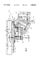
- FIG. 4 is an enlarged cross-sectional view of the multi oil furnace taken along lines 4--4 of FIG. 3 to better show the burner assembly;
- FIG. 5 is an enlarged partial cross-sectional view of the burner assembly taken along lines 5--5 of FIG. 2 to depict a top view of the preheater block;
- FIG. 6 is a schematic wiring diagram of the electrical circuit for the multi oil furnace.
- the furnace 10 includes a cabinet shell 19 enveloping a heat exchanger 12 and a central burner chamber 15.
- a burner assembly 20 is mounted on the front door 11 to fire a flame into the burner chamber 15 toward a target 17 mounted on the back wall 18 of the burner chamber 15.
- the heat exchanger 12 allows the circulation of clean air to be heated around pipes 13 carrying heated combustion gases before being discharged from the furnace 12.
- the furnace 12 incorporates a ventilation air inlet opening 14a and a ventilation air exit opening 14b to provide for the passage of the clean ventilation air to be heated through the heat exchanger 12.
- the burner assembly 20 includes a burner nozzle 21 and an igniter 22 to create a flame from the used oil supplied thereto, as described in greater detail below, a combustion air fan 25 and associated motor 26, and a preheater block 30 mounting various controls for the flow of used oil and compressed air to the burner nozzle 21, as will also be described in greater detail below.
- the burner assembly 20 is mounted within a burner housing 70, as will also be described in greater detail below.
- the preheater block 30 defines two separate flow paths for used oil and compressed air, respectively.
- the preheater block 30 is formed with a heater chamber 32 in which is housed a heating element 33, electrically coupled to a preheater thermostat 34 and a power supply 62.
- the heating element 33 is removably mounted within the heater chamber 32 and provides a source of heat when electrical current is passed through the heating element 33.
- the preheater block 30 is formed of metallic material, such as aluminum, and is, therefore, conductive of the heat generated by the heating element 33.
- the flow of used oil is introduced into the preheater block 30 from the line 28 delivering unheated used oil from an external tank (not shown) to the inlet port 41.
- the flow path for the used oil through the preheater block 30 makes approximately seven passes through the block 30 before exiting the outlet port 44 to absorb conductive heat to enable the delivery of used oil preheated to a predetermined temperature to the burner nozzle 21.
- An oil flow regulator 45 is manually operable to control the rate of flow of used oil through the block 30 and, therefore, to the burner nozzle 21.
- a solenoid shut-off mechanism 46 is coupled to the oil flow path immediately adjacent the oil outlet port 44 to minimize the amount of used oil that can drip through the burner nozzle 21.
- An oil pressure gauge 48 is tapped into the oil flow path down stream from the solenoid shut-off 46 to register the flow of used oil to the burner nozzle 21.
- the flow of compressed air is introduced into the preheater block 30 through the air inlet port 51 from a connecting line 29 couple to a conventional source of compressed air (not shown).
- the flow path for the compressed air through the preheater block 30 makes approximately three passes through the block 30 to absorb sufficient conductive heat from the block 30 to raise the temperature to approximately the same level as the used oil before exiting the outlet port 54 for delivery of preheated compressed air to the burner nozzle 21.
- An air flow regulator 55 is manually operable to control the flow of compressed air through the block 30.
- a solenoid shut-off mechanism 56 is operable to halt the flow of compressed air through the system.
- An air pressure gauge 59 is tapped into the compressed air flow path down stream from the solenoid shut-off 56 to register the flow of compressed air to the burner nozzle 21.
- An air sensing switch 58 detects the presence of compressed air flowing to the burner nozzle 21 and is operable to prevent the oil solenoid shut-off 46 from opening whenever compressed air is not present in the system.
- the burner housing 70 is divided into three compartments 71, 72 and 73, respectively, to improve serviceability of the controls and operative components of the furnace 10.
- the preheater block 30 and associated operative controls are supported in the first housing compartment 71.
- the used oil connecting line 28 and the compressed air connecting line 29 pass through corresponding openings in the right side wall 74 to connect with the respective inlet ports 41, 51 of the preheater block 30.
- the interior wall 76 separating the first and second housing compartments 71, 72 is provided with appropriate openings for the passage of the connecting lines 28a, 29a for the supply of preheated used oil and compressed air, respectively, to the burner nozzle 21.
- the burner nozzle 21 is supported from the preheater block 30 in a cantilever fashion by the connecting lines 28a, 29a supplying preheated used oil and compressed air to the burner nozzle 21 and is positioned within the second housing compartment 72, separated from the first housing compartment 71 by the interior wall 76.
- the function of the nozzle 21 is to combine the flows of compressed air and used oil from the preheater block 30 to create a stream of compressed air and atomized used oil droplets to be ejected from the nozzle 21 into the burner chamber 15.
- the igniter 22 is detachably mounted to the burner nozzle 21 by the fastener 22a to locate the igniter electrodes 23 in the proper position relative to the nozzle 21 for ignition of the stream of compressed air and atomized used oil droplets.
- a fan 25 for supplying quantities of combustion air into the burner chamber 15 is rotatably mounted in the second housing compartment 72 below the burner nozzle 21.
- the rotatable fan 25 draws combustion air from the atmosphere around the furnace 10 through an air inlet opening 78 in the left side wall 77.
- Adjustment louvers 79 are movable relative to the left side wall 77 to control the effective size of the air inlet opening 78 and, thereby, control the volume of combustion air being blown into the burner chamber 15.
- the curved outer peripheral surface 75 of the second compartment 72 directs the flow of combustion air over the burner nozzle 21 and through the discharge opening 80 into the burner chamber 15 to provide sufficient oxygen to support the burning of the flame therein.
- Each of the housing compartments 71, 72 and 73 is provided with its own removable cover 81, 82 and 83, respectively.
- the first compartment cover 81 is hinged to the right side wall 74 and opens to expose the entire preheater block 30 and attached components for servicing, testing, etc.
- the first compartment cover 81 has a pair of apertures through the top surface to expose the oil and air regulators 45, 55 for manual manipulation without requiring the cover 81 to be opened.
- the third compartment cover 83 is simply attached to the right side wall 74 to cover an access opening therein to allow access to the fan motor 26.
- the second compartment cover 82 is hinged to and forms a portion of the curved outer peripheral portion 75 of the second compartment 72.
- a power transformer 63 which receives electrical power from the primary source of electrical power 62, is mounted on the second compartment cover 82 and operatively extends into the second housing compartment 72.
- the electrodes 23 of the igniter 22 extend upwardly from the insulator block 24 to contact the power transformer 63 and receive electrical current therefrom to ignite the stream of compressed air and used oil droplets ejected from the burner nozzle 21 by creating a spark in a conventional manner.
- the transformer 63 is disconnected from the electrodes 23, but also has contact broken with the primary power source 62.
- the primary power source 62 One skilled in the art will readily realize that once the flame has started, the continuous ejection of the stream of compressed air and atomized used oil droplets will be self-igniting and does not require the use of the power transformer 63 to continue operation of the furnace 10.
- Regular maintenance of the burner assembly 20 includes an annual replacement of the igniter 22.
- access to the igniter 22 and inspection of both the burner nozzle 21 and the combustion air fan 25 is conveniently available through the second compartment cover 82.
- the compartmentalized burner housing 70 By use of the compartmentalized burner housing 70, access to the preheater block 30 and associated components and to the combustion air fan motor 26 can be attained without disrupting the flow of combustion air within the second housing compartment 72 over the burner nozzle 21 and igniter 22 to the burner chamber 15. Furthermore, the separation of the operative components from the combustion air flow minimizes the exposure of these components to the dust and dirt that is associated with the supply of combustion air and to the oxidizing effects of the proximate open flame.
- the operative gauges such as the oil pressure gauge 48 and the air pressure gauge 59, can be mounted to the exterior of the housing 70 for readability without moving a compartment cover 81-83.
- the front door 11 is pivotally connected to the cabinet shell 19 by door hinges 86 and is pivotally movable between a closed position, in which the front door 11 is bolted to the cabinet shell 19 by bolts 87, as shown in solid lines in FIGS. 1, 2 and 3, and an opened position, as shown in phantom in FIGS. 1 and 3.
- the movement of the front door 11 to the opened position allows access to the burner chamber 15 and the heat exchanger 12 for service or repairs thereto.
- the burner housing 70 which is mounted to the front door 11, as described in greater detail below, swings outwardly with the front door 11.
- the burner housing 70 in which is mounted the burner assembly 20, as described above, is pivotally mounted to the front door 11 by housing hinges 88 which enable the burner housing 70 to be pivotally moved between a closed operative position shown in solid lines in FIGS. 1, 2 and 3 and an opened inoperative or service position shown in phantom lines in FIGS. 1 and 3.
- the burner housing 70 is fastened to the front door 11 by the fastener 89 to prevent and accidental opening of the burner housing 70 while the furnace 10 is operating.
- a regular maintenance duty is to clean the tip 21a of the burner nozzle 21.
- cleaning the burner nozzle tip 21a is a relatively simple task involving the removal of the fastener 89 and the swinging outwardly of the burner housing 70 about the housing hinges 88 to expose the tip 21a for servicing or replacement, if necessary.
- the front door 11 is provided with a burner opening 11a for insertion of the burner tube 85 defining the discharge opening 80 therethrough to expose the burner nozzle tip 21a to the burner chamber 15 for the firing of a flame toward the target 17.
- the burner housing 70 seals against the front door 11 when in the operative position.
- the primary power supply 62 is shown in the form of a junction box 91 affixed to the cabinet shell 19 above the front door 11. Electrical power is transferred to the burner assembly 20 by a power cable 92 extending downwardly, overlapping the front door 11, for connection to the control system 60 for the burner assembly 20.
- the power cable 92 is configured so as to take the shortest possible route between the junction box 90 and the burner assembly 20.
- the power cable 92 cannot accommodate the increase in distance, the power cable 92 must be disconnected from the junction box 90, or preferably from the burner assembly 20, to enable the burner housing 70 to swing out for servicing. Accordingly, electrical power to the burner assembly 20 will necessarily be disconnected whenever the burner housing is moved for servicing any component of the furnace 10, including movements associated with the movement of the front door to the opened position.
- the used oil supply line 28 includes a rotatable coupling 95, preferably a conventional quick disconnect coupling, mounted to a connector block 99 in line with the pivot axis 96 coinciding with the housing hinges 88 about which the burner housing 70 pivots when moving to the inoperative or service position independently of the front door 11. Accordingly, whenever the burner housing 70 moves about the pivot axis 96 relative to the front door 11, the used oil connecting line 28, which is preferably a rigid copper tube, can rotate about the rotatable coupling 95 and not require disconnection to swing the burner housing 70 for servicing the burner nozzle tip 21a.
- a rotatable coupling 95 preferably a conventional quick disconnect coupling
- the compressed air supply line 29 is preferably flexible black nylon tubing, but is nevertheless connected to a swivel fitting 97, supported by the connector block 99 adjacent the rotatable coupling 95, to allow some positional displacement of the compressed air connecting line 29 when the burner housing 70 is pivoted to the inoperative position because the swivel fitting 97 is not aligned with the pivot axis 96.
- the connector block 99 is fixed to the bottom of the front door 11 for connection to appropriate supply lines to remote sources of used oil and compressed air.
- the connector block 99 and connecting lines 28, 29 are utilized to standardize the furnace system beginning with the connector block 99, as the typical installation of a furnace 10 will require an on-site connection of the remote supply lines to the connector block 99.
- the control mechanism 60 operatively interconnects several switches and sensors to control the operation of the furnace 10. For example, if the flow of compressed air is interrupted through the air flow path 50, as sensed by the air sensing switch or the de-energizing of the air solenoid shut-off valve 56, the oil solenoid shut-off valve 46 is immediately de-energized to stop the flow of used oil through the oil flow path 40 to the burner nozzle 21.
- a proving switch 64 is mounted on the preheater block 30 and will not allow the furnace 10 to operate unless the preheater block 30 has been warmed to the predetermined temperature by the heating element 33.
- a CAD cell 68 is operable to detect the existence of a flame within the burner chamber 15. The control mechanism 60 will automatically de-energize the air and oil solenoid shut-off valves 46, 56 if a flame in the burner chamber 15 is not detected immediately after heat is called for by the wall thermostat 66.
Abstract
Description
Claims (18)
Priority Applications (1)
| Application Number | Priority Date | Filing Date | Title |
|---|---|---|---|
| US08/227,258 US5408941A (en) | 1994-04-14 | 1994-04-14 | Multi oil furnace service doors |
Applications Claiming Priority (1)
| Application Number | Priority Date | Filing Date | Title |
|---|---|---|---|
| US08/227,258 US5408941A (en) | 1994-04-14 | 1994-04-14 | Multi oil furnace service doors |
Publications (1)
| Publication Number | Publication Date |
|---|---|
| US5408941A true US5408941A (en) | 1995-04-25 |
Family
ID=22852404
Family Applications (1)
| Application Number | Title | Priority Date | Filing Date |
|---|---|---|---|
| US08/227,258 Expired - Lifetime US5408941A (en) | 1994-04-14 | 1994-04-14 | Multi oil furnace service doors |
Country Status (1)
| Country | Link |
|---|---|
| US (1) | US5408941A (en) |
Cited By (1)
| Publication number | Priority date | Publication date | Assignee | Title |
|---|---|---|---|---|
| US20120125241A1 (en) * | 2010-05-20 | 2012-05-24 | Phil See | Waste Oil Furnace |
Citations (9)
| Publication number | Priority date | Publication date | Assignee | Title |
|---|---|---|---|---|
| US1493820A (en) * | 1920-01-22 | 1924-05-13 | Carl D Miller | Fuel-oil burner |
| US1733499A (en) * | 1926-05-04 | 1929-10-29 | Herman G Klemm | Burner mounting |
| GB339192A (en) * | 1930-02-05 | 1930-12-04 | Thomas Bonner Coilins | Improvements relating to liquid fuel, gas or like burners of furnaces |
| US2841215A (en) * | 1952-06-26 | 1958-07-01 | Messer Company Inc | Oil burner assembly including an oil preheater |
| US3070151A (en) * | 1958-07-09 | 1962-12-25 | Stookunie N V | Oilburners |
| US3977823A (en) * | 1975-07-02 | 1976-08-31 | Frank Bernhard | Method of burning residual fuel oil in distillate fuel oil burners |
| US4162887A (en) * | 1977-05-23 | 1979-07-31 | Greenmace Limited | Oil burner |
| US4460328A (en) * | 1980-12-29 | 1984-07-17 | Niederholtmeyer Werner J | Process and apparatus for utilizing waste oil |
| US4877395A (en) * | 1987-06-22 | 1989-10-31 | Gary Schubach | System control means to preheat waste oil for combustion |
-
1994
- 1994-04-14 US US08/227,258 patent/US5408941A/en not_active Expired - Lifetime
Patent Citations (9)
| Publication number | Priority date | Publication date | Assignee | Title |
|---|---|---|---|---|
| US1493820A (en) * | 1920-01-22 | 1924-05-13 | Carl D Miller | Fuel-oil burner |
| US1733499A (en) * | 1926-05-04 | 1929-10-29 | Herman G Klemm | Burner mounting |
| GB339192A (en) * | 1930-02-05 | 1930-12-04 | Thomas Bonner Coilins | Improvements relating to liquid fuel, gas or like burners of furnaces |
| US2841215A (en) * | 1952-06-26 | 1958-07-01 | Messer Company Inc | Oil burner assembly including an oil preheater |
| US3070151A (en) * | 1958-07-09 | 1962-12-25 | Stookunie N V | Oilburners |
| US3977823A (en) * | 1975-07-02 | 1976-08-31 | Frank Bernhard | Method of burning residual fuel oil in distillate fuel oil burners |
| US4162887A (en) * | 1977-05-23 | 1979-07-31 | Greenmace Limited | Oil burner |
| US4460328A (en) * | 1980-12-29 | 1984-07-17 | Niederholtmeyer Werner J | Process and apparatus for utilizing waste oil |
| US4877395A (en) * | 1987-06-22 | 1989-10-31 | Gary Schubach | System control means to preheat waste oil for combustion |
Non-Patent Citations (4)
| Title |
|---|
| Aug. 25, 1992, Clean Burn Operator s Manual for Models CB 90 AH and CB 90 BH with CB 90 HS Burner. * |
| Aug. 25, 1992, Clean Burn Operator's Manual for Models CB-90-AH and CB-90-BH with CB-90-HS Burner. |
| Jun., 1990, Reznor sales brochure for "Waste Oil Heater". |
| Jun., 1990, Reznor sales brochure for Waste Oil Heater . * |
Cited By (1)
| Publication number | Priority date | Publication date | Assignee | Title |
|---|---|---|---|---|
| US20120125241A1 (en) * | 2010-05-20 | 2012-05-24 | Phil See | Waste Oil Furnace |
Similar Documents
| Publication | Publication Date | Title |
|---|---|---|
| EP0104273B1 (en) | Power burner system for a food preparation oven | |
| US6244223B1 (en) | Power burner type fuel-fired water heater with quick change manifold assembly | |
| US4211735A (en) | Humidifier nozzle mounting | |
| CN1003731B (en) | Vehicle heater actuating by fuel oil | |
| CN101517319A (en) | Gas-fired portable unvented infrared heater | |
| CA2153632C (en) | Deep frying apparatus | |
| US5409373A (en) | Burner housing for multi oil furnaces | |
| US5408941A (en) | Multi oil furnace service doors | |
| US20050036770A1 (en) | Hybrid hot air heater | |
| WO1984001015A1 (en) | Oil burner | |
| EP0387983B1 (en) | Water heater | |
| US5531212A (en) | Multi oil furnace | |
| US6795643B2 (en) | Hybrid hotair heater | |
| US5494025A (en) | Heat exchanger for multi oil furnaces | |
| US6955535B2 (en) | Array for an automatic firing device for a gas or oil burner | |
| CA1251698A (en) | High-efficiency thermal group | |
| US4688718A (en) | Intermediate housing for a fuel-operated heater | |
| US2578927A (en) | Duplex heater | |
| US20100101505A1 (en) | Transition element for a passage in a water heater | |
| US5490495A (en) | Cleanout header for multi oil furnaces | |
| US3606608A (en) | Encasement and fuel burner assembly | |
| CN210831987U (en) | Gas distributor and gas water heater comprising same | |
| KR0133325B1 (en) | Exhaust equipment of a rotary heater | |
| CN208365962U (en) | The device that a kind of pair of slag pan is preheated | |
| CN217978937U (en) | Gas-electric dual-purpose combined stove |
Legal Events
| Date | Code | Title | Description |
|---|---|---|---|
| AS | Assignment |
Owner name: CLEAN BURN, INC., PENNSYLVANIA Free format text: ASSIGNMENT OF ASSIGNORS INTEREST;ASSIGNORS:BEILER, EMANUEL S.;SMOKER, BENUEL F.;YODER, DAVID J.;REEL/FRAME:006956/0419 Effective date: 19940413 |
|
| STCF | Information on status: patent grant |
Free format text: PATENTED CASE |
|
| FPAY | Fee payment |
Year of fee payment: 4 |
|
| FPAY | Fee payment |
Year of fee payment: 8 |
|
| REMI | Maintenance fee reminder mailed | ||
| FPAY | Fee payment |
Year of fee payment: 12 |
|
| AS | Assignment |
Owner name: CLEAN BURN, LLC, WISCONSIN Free format text: CHANGE OF NAME;ASSIGNOR:CB ACQUISITION, LLC;REEL/FRAME:025366/0330 Effective date: 20101112 Owner name: CB ACQUISITION, LLC, WISCONSIN Free format text: ASSIGNMENT OF ASSIGNORS INTEREST;ASSIGNOR:CLEAN BURN, INC.;REEL/FRAME:025366/0139 Effective date: 20101112 Owner name: ALDINE SBIC FUND, L.P., ILLINOIS Free format text: AMENDED AND RESTATED GRANT OF SECURITY INTEREST;ASSIGNOR:CLEAN BURN LLC, FORMERLY CB ACQUISITION, LLC;REEL/FRAME:025366/0016 Effective date: 20101112 |
|
| AS | Assignment |
Owner name: FIRST BUSINESS BANK, WISCONSIN Free format text: SECURITY AGREEMENT;ASSIGNOR:CB ACQUISITION, LLC;REEL/FRAME:025437/0464 Effective date: 20101112 |
|
| AS | Assignment |
Owner name: NORTHCREEK MEZZANINE FUND II, L.P., OHIO Free format text: SECURITY INTEREST;ASSIGNOR:CLEAN BURN, LLC;REEL/FRAME:038342/0015 Effective date: 20160419 |
|
| AS | Assignment |
Owner name: BMO HARRIS BANK N.A., WISCONSIN Free format text: SECURITY INTEREST;ASSIGNOR:CLEAN BURN, LLC;REEL/FRAME:050301/0506 Effective date: 20190906 |
|
| AS | Assignment |
Owner name: CLEAN BURN, LLC, WISCONSIN Free format text: RELEASE BY SECURED PARTY;ASSIGNOR:BMO HARRIS BANK N.A.;REEL/FRAME:057507/0065 Effective date: 20210915 Owner name: CLEAN BURN, LLC, WISCONSIN Free format text: SECURITY INTEREST;ASSIGNOR:BMO HARRIS BANK N.A.;REEL/FRAME:057506/0552 Effective date: 20210915 |
|
| AS | Assignment |
Owner name: CLEAN BURN, LLC (FORMERLY CB ACQUISITION, LLC), WISCONSIN Free format text: RELEASE BY SECURED PARTY;ASSIGNOR:ALDINE SBIC FUND, L.P.;REEL/FRAME:057550/0851 Effective date: 20210915 Owner name: LANAIR PRODUCTS, LLC, WISCONSIN Free format text: RELEASE BY SECURED PARTY;ASSIGNOR:ALDINE SBIC FUND, L.P.;REEL/FRAME:057550/0851 Effective date: 20210915 Owner name: CLEAN BURN, LLC, WISCONSIN Free format text: RELEASE BY SECURED PARTY;ASSIGNOR:NORTHCREEK MEZZANINE FUND II, L.P.;REEL/FRAME:057550/0810 Effective date: 20210915 Owner name: LANAIR PRODUCTS, LLC, WISCONSIN Free format text: RELEASE BY SECURED PARTY;ASSIGNOR:NORTHCREEK MEZZANINE FUND II, L.P.;REEL/FRAME:057550/0810 Effective date: 20210915 |