US5407734A - Fiber-containing composite - Google Patents
Fiber-containing composite Download PDFInfo
- Publication number
- US5407734A US5407734A US07/260,201 US26020188A US5407734A US 5407734 A US5407734 A US 5407734A US 26020188 A US26020188 A US 26020188A US 5407734 A US5407734 A US 5407734A
- Authority
- US
- United States
- Prior art keywords
- matrix
- fibrous material
- filaments
- composite
- comprised
- Prior art date
- Legal status (The legal status is an assumption and is not a legal conclusion. Google has not performed a legal analysis and makes no representation as to the accuracy of the status listed.)
- Expired - Fee Related
Links
- 239000002131 composite material Substances 0.000 title claims abstract description 95
- 239000000835 fiber Substances 0.000 title claims description 11
- 239000002657 fibrous material Substances 0.000 claims abstract description 89
- 239000000463 material Substances 0.000 claims abstract description 45
- 239000000919 ceramic Substances 0.000 claims abstract description 39
- 239000002002 slurry Substances 0.000 claims abstract description 31
- 238000007731 hot pressing Methods 0.000 claims abstract description 19
- 238000010030 laminating Methods 0.000 claims abstract description 5
- 239000011159 matrix material Substances 0.000 claims description 60
- 239000010410 layer Substances 0.000 claims description 44
- 238000000034 method Methods 0.000 claims description 35
- 229910052845 zircon Inorganic materials 0.000 claims description 26
- GFQYVLUOOAAOGM-UHFFFAOYSA-N zirconium(iv) silicate Chemical compound [Zr+4].[O-][Si]([O-])([O-])[O-] GFQYVLUOOAAOGM-UHFFFAOYSA-N 0.000 claims description 26
- 239000011230 binding agent Substances 0.000 claims description 25
- HBMJWWWQQXIZIP-UHFFFAOYSA-N silicon carbide Chemical compound [Si+]#[C-] HBMJWWWQQXIZIP-UHFFFAOYSA-N 0.000 claims description 23
- 229910010271 silicon carbide Inorganic materials 0.000 claims description 20
- OKTJSMMVPCPJKN-UHFFFAOYSA-N Carbon Chemical compound [C] OKTJSMMVPCPJKN-UHFFFAOYSA-N 0.000 claims description 17
- 229910052799 carbon Inorganic materials 0.000 claims description 14
- 229910052751 metal Inorganic materials 0.000 claims description 10
- 239000002184 metal Substances 0.000 claims description 10
- 239000007788 liquid Substances 0.000 claims description 8
- 229910052757 nitrogen Inorganic materials 0.000 claims description 8
- 230000002939 deleterious effect Effects 0.000 claims description 7
- 229910052760 oxygen Inorganic materials 0.000 claims description 6
- 238000010438 heat treatment Methods 0.000 claims description 5
- 229910052581 Si3N4 Inorganic materials 0.000 claims description 4
- 229910010293 ceramic material Inorganic materials 0.000 claims description 4
- 239000007795 chemical reaction product Substances 0.000 claims description 4
- KZHJGOXRZJKJNY-UHFFFAOYSA-N dioxosilane;oxo(oxoalumanyloxy)alumane Chemical compound O=[Si]=O.O=[Si]=O.O=[Al]O[Al]=O.O=[Al]O[Al]=O.O=[Al]O[Al]=O KZHJGOXRZJKJNY-UHFFFAOYSA-N 0.000 claims description 4
- 238000001704 evaporation Methods 0.000 claims description 4
- 229910052863 mullite Inorganic materials 0.000 claims description 4
- HQVNEWCFYHHQES-UHFFFAOYSA-N silicon nitride Chemical compound N12[Si]34N5[Si]62N3[Si]51N64 HQVNEWCFYHHQES-UHFFFAOYSA-N 0.000 claims description 4
- 229910052582 BN Inorganic materials 0.000 claims description 3
- PZNSFCLAULLKQX-UHFFFAOYSA-N Boron nitride Chemical compound N#B PZNSFCLAULLKQX-UHFFFAOYSA-N 0.000 claims description 3
- 238000005266 casting Methods 0.000 claims description 3
- 239000004744 fabric Substances 0.000 claims description 3
- 239000011236 particulate material Substances 0.000 claims description 3
- 229910052710 silicon Inorganic materials 0.000 claims description 3
- 239000010703 silicon Substances 0.000 claims description 3
- 229910002106 crystalline ceramic Inorganic materials 0.000 claims 2
- 239000011222 crystalline ceramic Substances 0.000 claims 2
- 238000010304 firing Methods 0.000 abstract description 3
- 238000000151 deposition Methods 0.000 abstract description 2
- 238000001035 drying Methods 0.000 abstract description 2
- 239000011368 organic material Substances 0.000 abstract description 2
- YXFVVABEGXRONW-UHFFFAOYSA-N Toluene Chemical compound CC1=CC=CC=C1 YXFVVABEGXRONW-UHFFFAOYSA-N 0.000 description 15
- 239000007787 solid Substances 0.000 description 10
- 239000000203 mixture Substances 0.000 description 9
- 239000000843 powder Substances 0.000 description 8
- 239000002904 solvent Substances 0.000 description 7
- LFQSCWFLJHTTHZ-UHFFFAOYSA-N Ethanol Chemical compound CCO LFQSCWFLJHTTHZ-UHFFFAOYSA-N 0.000 description 6
- 239000004014 plasticizer Substances 0.000 description 6
- 238000003475 lamination Methods 0.000 description 5
- 239000002245 particle Substances 0.000 description 5
- 229920002037 poly(vinyl butyral) polymer Polymers 0.000 description 5
- XKRFYHLGVUSROY-UHFFFAOYSA-N Argon Chemical compound [Ar] XKRFYHLGVUSROY-UHFFFAOYSA-N 0.000 description 4
- IJGRMHOSHXDMSA-UHFFFAOYSA-N Atomic nitrogen Chemical compound N#N IJGRMHOSHXDMSA-UHFFFAOYSA-N 0.000 description 4
- 238000000354 decomposition reaction Methods 0.000 description 4
- 238000011049 filling Methods 0.000 description 4
- 238000001764 infiltration Methods 0.000 description 4
- 230000008595 infiltration Effects 0.000 description 4
- 238000004519 manufacturing process Methods 0.000 description 4
- ZWEHNKRNPOVVGH-UHFFFAOYSA-N 2-Butanone Chemical compound CCC(C)=O ZWEHNKRNPOVVGH-UHFFFAOYSA-N 0.000 description 3
- 229920002799 BoPET Polymers 0.000 description 3
- 239000005041 Mylar™ Substances 0.000 description 3
- 239000002390 adhesive tape Substances 0.000 description 3
- 238000007596 consolidation process Methods 0.000 description 3
- 238000007796 conventional method Methods 0.000 description 3
- 235000019441 ethanol Nutrition 0.000 description 3
- 238000005979 thermal decomposition reaction Methods 0.000 description 3
- OCKGFTQIICXDQW-ZEQRLZLVSA-N 5-[(1r)-1-hydroxy-2-[4-[(2r)-2-hydroxy-2-(4-methyl-1-oxo-3h-2-benzofuran-5-yl)ethyl]piperazin-1-yl]ethyl]-4-methyl-3h-2-benzofuran-1-one Chemical compound C1=C2C(=O)OCC2=C(C)C([C@@H](O)CN2CCN(CC2)C[C@H](O)C2=CC=C3C(=O)OCC3=C2C)=C1 OCKGFTQIICXDQW-ZEQRLZLVSA-N 0.000 description 2
- CSCPPACGZOOCGX-UHFFFAOYSA-N Acetone Chemical compound CC(C)=O CSCPPACGZOOCGX-UHFFFAOYSA-N 0.000 description 2
- NTIZESTWPVYFNL-UHFFFAOYSA-N Methyl isobutyl ketone Chemical compound CC(C)CC(C)=O NTIZESTWPVYFNL-UHFFFAOYSA-N 0.000 description 2
- UIHCLUNTQKBZGK-UHFFFAOYSA-N Methyl isobutyl ketone Natural products CCC(C)C(C)=O UIHCLUNTQKBZGK-UHFFFAOYSA-N 0.000 description 2
- MCMNRKCIXSYSNV-UHFFFAOYSA-N Zirconium dioxide Chemical compound O=[Zr]=O MCMNRKCIXSYSNV-UHFFFAOYSA-N 0.000 description 2
- 229910052786 argon Inorganic materials 0.000 description 2
- 238000005229 chemical vapour deposition Methods 0.000 description 2
- 239000011248 coating agent Substances 0.000 description 2
- 238000000576 coating method Methods 0.000 description 2
- 238000005336 cracking Methods 0.000 description 2
- 230000007423 decrease Effects 0.000 description 2
- 238000000280 densification Methods 0.000 description 2
- 229910003460 diamond Inorganic materials 0.000 description 2
- 239000010432 diamond Substances 0.000 description 2
- DOIRQSBPFJWKBE-UHFFFAOYSA-N dibutyl phthalate Chemical compound CCCCOC(=O)C1=CC=CC=C1C(=O)OCCCC DOIRQSBPFJWKBE-UHFFFAOYSA-N 0.000 description 2
- 230000008020 evaporation Effects 0.000 description 2
- 238000009730 filament winding Methods 0.000 description 2
- 239000007789 gas Substances 0.000 description 2
- 229910002804 graphite Inorganic materials 0.000 description 2
- 239000010439 graphite Substances 0.000 description 2
- 238000000386 microscopy Methods 0.000 description 2
- 239000003960 organic solvent Substances 0.000 description 2
- 230000035515 penetration Effects 0.000 description 2
- 239000000047 product Substances 0.000 description 2
- 238000004626 scanning electron microscopy Methods 0.000 description 2
- 229920002545 silicone oil Polymers 0.000 description 2
- 239000002356 single layer Substances 0.000 description 2
- 239000000126 substance Substances 0.000 description 2
- 239000000758 substrate Substances 0.000 description 2
- 239000000725 suspension Substances 0.000 description 2
- UHDNUPHSDMOGCR-UHFFFAOYSA-N 3-Formylbenzoic acid Chemical compound OC(=O)C1=CC=CC(C=O)=C1 UHDNUPHSDMOGCR-UHFFFAOYSA-N 0.000 description 1
- RYGMFSIKBFXOCR-UHFFFAOYSA-N Copper Chemical compound [Cu] RYGMFSIKBFXOCR-UHFFFAOYSA-N 0.000 description 1
- MQIUGAXCHLFZKX-UHFFFAOYSA-N Di-n-octyl phthalate Natural products CCCCCCCCOC(=O)C1=CC=CC=C1C(=O)OCCCCCCCC MQIUGAXCHLFZKX-UHFFFAOYSA-N 0.000 description 1
- CTQNGGLPUBDAKN-UHFFFAOYSA-N O-Xylene Chemical compound CC1=CC=CC=C1C CTQNGGLPUBDAKN-UHFFFAOYSA-N 0.000 description 1
- 239000004952 Polyamide Substances 0.000 description 1
- 239000002202 Polyethylene glycol Substances 0.000 description 1
- 239000004793 Polystyrene Substances 0.000 description 1
- 239000004809 Teflon Substances 0.000 description 1
- 229920006362 Teflon® Polymers 0.000 description 1
- BAECOWNUKCLBPZ-HIUWNOOHSA-N Triolein Natural products O([C@H](OCC(=O)CCCCCCC/C=C\CCCCCCCC)COC(=O)CCCCCCC/C=C\CCCCCCCC)C(=O)CCCCCCC/C=C\CCCCCCCC BAECOWNUKCLBPZ-HIUWNOOHSA-N 0.000 description 1
- PHYFQTYBJUILEZ-UHFFFAOYSA-N Trioleoylglycerol Natural products CCCCCCCCC=CCCCCCCCC(=O)OCC(OC(=O)CCCCCCCC=CCCCCCCCC)COC(=O)CCCCCCCC=CCCCCCCCC PHYFQTYBJUILEZ-UHFFFAOYSA-N 0.000 description 1
- HMDDXIMCDZRSNE-UHFFFAOYSA-N [C].[Si] Chemical compound [C].[Si] HMDDXIMCDZRSNE-UHFFFAOYSA-N 0.000 description 1
- 150000001252 acrylic acid derivatives Chemical class 0.000 description 1
- 230000015572 biosynthetic process Effects 0.000 description 1
- BJQHLKABXJIVAM-UHFFFAOYSA-N bis(2-ethylhexyl) phthalate Chemical compound CCCCC(CC)COC(=O)C1=CC=CC=C1C(=O)OCC(CC)CCCC BJQHLKABXJIVAM-UHFFFAOYSA-N 0.000 description 1
- 239000011153 ceramic matrix composite Substances 0.000 description 1
- 238000004814 ceramic processing Methods 0.000 description 1
- 239000011889 copper foil Substances 0.000 description 1
- 239000013078 crystal Substances 0.000 description 1
- 238000006073 displacement reaction Methods 0.000 description 1
- 238000009826 distribution Methods 0.000 description 1
- 230000000694 effects Effects 0.000 description 1
- 238000000227 grinding Methods 0.000 description 1
- 229910052734 helium Inorganic materials 0.000 description 1
- 239000001307 helium Substances 0.000 description 1
- SWQJXJOGLNCZEY-UHFFFAOYSA-N helium atom Chemical compound [He] SWQJXJOGLNCZEY-UHFFFAOYSA-N 0.000 description 1
- 238000011068 loading method Methods 0.000 description 1
- 229910003465 moissanite Inorganic materials 0.000 description 1
- 229920000620 organic polymer Polymers 0.000 description 1
- 230000001590 oxidative effect Effects 0.000 description 1
- 229920003023 plastic Polymers 0.000 description 1
- 239000004033 plastic Substances 0.000 description 1
- 229920002647 polyamide Polymers 0.000 description 1
- 229920001223 polyethylene glycol Polymers 0.000 description 1
- 229920000193 polymethacrylate Polymers 0.000 description 1
- 229920002223 polystyrene Polymers 0.000 description 1
- 229920002689 polyvinyl acetate Polymers 0.000 description 1
- 229920002451 polyvinyl alcohol Polymers 0.000 description 1
- 235000019422 polyvinyl alcohol Nutrition 0.000 description 1
- 239000011148 porous material Substances 0.000 description 1
- 239000002243 precursor Substances 0.000 description 1
- 238000003825 pressing Methods 0.000 description 1
- 238000012545 processing Methods 0.000 description 1
- 230000001681 protective effect Effects 0.000 description 1
- 239000002296 pyrolytic carbon Substances 0.000 description 1
- 239000011226 reinforced ceramic Substances 0.000 description 1
- 230000002787 reinforcement Effects 0.000 description 1
- 239000012783 reinforcing fiber Substances 0.000 description 1
- 238000007569 slipcasting Methods 0.000 description 1
- 238000001778 solid-state sintering Methods 0.000 description 1
- 238000010561 standard procedure Methods 0.000 description 1
- 238000010345 tape casting Methods 0.000 description 1
- 239000012815 thermoplastic material Substances 0.000 description 1
- PHYFQTYBJUILEZ-IUPFWZBJSA-N triolein Chemical compound CCCCCCCC\C=C/CCCCCCCC(=O)OCC(OC(=O)CCCCCCC\C=C/CCCCCCCC)COC(=O)CCCCCCC\C=C/CCCCCCCC PHYFQTYBJUILEZ-IUPFWZBJSA-N 0.000 description 1
- WFKWXMTUELFFGS-UHFFFAOYSA-N tungsten Chemical compound [W] WFKWXMTUELFFGS-UHFFFAOYSA-N 0.000 description 1
- 229910052721 tungsten Inorganic materials 0.000 description 1
- 239000010937 tungsten Substances 0.000 description 1
- 229920002554 vinyl polymer Polymers 0.000 description 1
- 239000011800 void material Substances 0.000 description 1
- 239000008096 xylene Substances 0.000 description 1
- 229910052726 zirconium Inorganic materials 0.000 description 1
Images

Classifications
-
- C—CHEMISTRY; METALLURGY
- C04—CEMENTS; CONCRETE; ARTIFICIAL STONE; CERAMICS; REFRACTORIES
- C04B—LIME, MAGNESIA; SLAG; CEMENTS; COMPOSITIONS THEREOF, e.g. MORTARS, CONCRETE OR LIKE BUILDING MATERIALS; ARTIFICIAL STONE; CERAMICS; REFRACTORIES; TREATMENT OF NATURAL STONE
- C04B35/00—Shaped ceramic products characterised by their composition; Ceramics compositions; Processing powders of inorganic compounds preparatory to the manufacturing of ceramic products
- C04B35/71—Ceramic products containing macroscopic reinforcing agents
- C04B35/78—Ceramic products containing macroscopic reinforcing agents containing non-metallic materials
- C04B35/80—Fibres, filaments, whiskers, platelets, or the like
-
- B—PERFORMING OPERATIONS; TRANSPORTING
- B32—LAYERED PRODUCTS
- B32B—LAYERED PRODUCTS, i.e. PRODUCTS BUILT-UP OF STRATA OF FLAT OR NON-FLAT, e.g. CELLULAR OR HONEYCOMB, FORM
- B32B18/00—Layered products essentially comprising ceramics, e.g. refractory products
-
- B—PERFORMING OPERATIONS; TRANSPORTING
- B32—LAYERED PRODUCTS
- B32B—LAYERED PRODUCTS, i.e. PRODUCTS BUILT-UP OF STRATA OF FLAT OR NON-FLAT, e.g. CELLULAR OR HONEYCOMB, FORM
- B32B5/00—Layered products characterised by the non- homogeneity or physical structure, i.e. comprising a fibrous, filamentary, particulate or foam layer; Layered products characterised by having a layer differing constitutionally or physically in different parts
- B32B5/22—Layered products characterised by the non- homogeneity or physical structure, i.e. comprising a fibrous, filamentary, particulate or foam layer; Layered products characterised by having a layer differing constitutionally or physically in different parts characterised by the presence of two or more layers which are next to each other and are fibrous, filamentary, formed of particles or foamed
-
- B—PERFORMING OPERATIONS; TRANSPORTING
- B32—LAYERED PRODUCTS
- B32B—LAYERED PRODUCTS, i.e. PRODUCTS BUILT-UP OF STRATA OF FLAT OR NON-FLAT, e.g. CELLULAR OR HONEYCOMB, FORM
- B32B9/00—Layered products comprising a layer of a particular substance not covered by groups B32B11/00 - B32B29/00
- B32B9/005—Layered products comprising a layer of a particular substance not covered by groups B32B11/00 - B32B29/00 comprising one layer of ceramic material, e.g. porcelain, ceramic tile
-
- B—PERFORMING OPERATIONS; TRANSPORTING
- B32—LAYERED PRODUCTS
- B32B—LAYERED PRODUCTS, i.e. PRODUCTS BUILT-UP OF STRATA OF FLAT OR NON-FLAT, e.g. CELLULAR OR HONEYCOMB, FORM
- B32B9/00—Layered products comprising a layer of a particular substance not covered by groups B32B11/00 - B32B29/00
- B32B9/04—Layered products comprising a layer of a particular substance not covered by groups B32B11/00 - B32B29/00 comprising such particular substance as the main or only constituent of a layer, which is next to another layer of the same or of a different material
- B32B9/047—Layered products comprising a layer of a particular substance not covered by groups B32B11/00 - B32B29/00 comprising such particular substance as the main or only constituent of a layer, which is next to another layer of the same or of a different material made of fibres or filaments
-
- C—CHEMISTRY; METALLURGY
- C04—CEMENTS; CONCRETE; ARTIFICIAL STONE; CERAMICS; REFRACTORIES
- C04B—LIME, MAGNESIA; SLAG; CEMENTS; COMPOSITIONS THEREOF, e.g. MORTARS, CONCRETE OR LIKE BUILDING MATERIALS; ARTIFICIAL STONE; CERAMICS; REFRACTORIES; TREATMENT OF NATURAL STONE
- C04B35/00—Shaped ceramic products characterised by their composition; Ceramics compositions; Processing powders of inorganic compounds preparatory to the manufacturing of ceramic products
- C04B35/01—Shaped ceramic products characterised by their composition; Ceramics compositions; Processing powders of inorganic compounds preparatory to the manufacturing of ceramic products based on oxide ceramics
- C04B35/16—Shaped ceramic products characterised by their composition; Ceramics compositions; Processing powders of inorganic compounds preparatory to the manufacturing of ceramic products based on oxide ceramics based on silicates other than clay
- C04B35/18—Shaped ceramic products characterised by their composition; Ceramics compositions; Processing powders of inorganic compounds preparatory to the manufacturing of ceramic products based on oxide ceramics based on silicates other than clay rich in aluminium oxide
- C04B35/185—Mullite 3Al2O3-2SiO2
-
- C—CHEMISTRY; METALLURGY
- C04—CEMENTS; CONCRETE; ARTIFICIAL STONE; CERAMICS; REFRACTORIES
- C04B—LIME, MAGNESIA; SLAG; CEMENTS; COMPOSITIONS THEREOF, e.g. MORTARS, CONCRETE OR LIKE BUILDING MATERIALS; ARTIFICIAL STONE; CERAMICS; REFRACTORIES; TREATMENT OF NATURAL STONE
- C04B35/00—Shaped ceramic products characterised by their composition; Ceramics compositions; Processing powders of inorganic compounds preparatory to the manufacturing of ceramic products
- C04B35/01—Shaped ceramic products characterised by their composition; Ceramics compositions; Processing powders of inorganic compounds preparatory to the manufacturing of ceramic products based on oxide ceramics
- C04B35/48—Shaped ceramic products characterised by their composition; Ceramics compositions; Processing powders of inorganic compounds preparatory to the manufacturing of ceramic products based on oxide ceramics based on zirconium or hafnium oxides, zirconates, zircon or hafnates
- C04B35/481—Shaped ceramic products characterised by their composition; Ceramics compositions; Processing powders of inorganic compounds preparatory to the manufacturing of ceramic products based on oxide ceramics based on zirconium or hafnium oxides, zirconates, zircon or hafnates containing silicon, e.g. zircon
-
- C—CHEMISTRY; METALLURGY
- C04—CEMENTS; CONCRETE; ARTIFICIAL STONE; CERAMICS; REFRACTORIES
- C04B—LIME, MAGNESIA; SLAG; CEMENTS; COMPOSITIONS THEREOF, e.g. MORTARS, CONCRETE OR LIKE BUILDING MATERIALS; ARTIFICIAL STONE; CERAMICS; REFRACTORIES; TREATMENT OF NATURAL STONE
- C04B35/00—Shaped ceramic products characterised by their composition; Ceramics compositions; Processing powders of inorganic compounds preparatory to the manufacturing of ceramic products
- C04B35/622—Forming processes; Processing powders of inorganic compounds preparatory to the manufacturing of ceramic products
- C04B35/64—Burning or sintering processes
- C04B35/645—Pressure sintering
-
- C—CHEMISTRY; METALLURGY
- C04—CEMENTS; CONCRETE; ARTIFICIAL STONE; CERAMICS; REFRACTORIES
- C04B—LIME, MAGNESIA; SLAG; CEMENTS; COMPOSITIONS THEREOF, e.g. MORTARS, CONCRETE OR LIKE BUILDING MATERIALS; ARTIFICIAL STONE; CERAMICS; REFRACTORIES; TREATMENT OF NATURAL STONE
- C04B37/00—Joining burned ceramic articles with other burned ceramic articles or other articles by heating
- C04B37/008—Joining burned ceramic articles with other burned ceramic articles or other articles by heating by means of an interlayer consisting of an organic adhesive, e.g. phenol resin or pitch
-
- D—TEXTILES; PAPER
- D01—NATURAL OR MAN-MADE THREADS OR FIBRES; SPINNING
- D01F—CHEMICAL FEATURES IN THE MANUFACTURE OF ARTIFICIAL FILAMENTS, THREADS, FIBRES, BRISTLES OR RIBBONS; APPARATUS SPECIALLY ADAPTED FOR THE MANUFACTURE OF CARBON FILAMENTS
- D01F11/00—Chemical after-treatment of artificial filaments or the like during manufacture
- D01F11/10—Chemical after-treatment of artificial filaments or the like during manufacture of carbon
- D01F11/12—Chemical after-treatment of artificial filaments or the like during manufacture of carbon with inorganic substances ; Intercalation
- D01F11/126—Carbides
-
- B—PERFORMING OPERATIONS; TRANSPORTING
- B32—LAYERED PRODUCTS
- B32B—LAYERED PRODUCTS, i.e. PRODUCTS BUILT-UP OF STRATA OF FLAT OR NON-FLAT, e.g. CELLULAR OR HONEYCOMB, FORM
- B32B2262/00—Composition or structural features of fibres which form a fibrous or filamentary layer or are present as additives
- B32B2262/10—Inorganic fibres
- B32B2262/105—Ceramic fibres
-
- B—PERFORMING OPERATIONS; TRANSPORTING
- B32—LAYERED PRODUCTS
- B32B—LAYERED PRODUCTS, i.e. PRODUCTS BUILT-UP OF STRATA OF FLAT OR NON-FLAT, e.g. CELLULAR OR HONEYCOMB, FORM
- B32B2262/00—Composition or structural features of fibres which form a fibrous or filamentary layer or are present as additives
- B32B2262/10—Inorganic fibres
- B32B2262/106—Carbon fibres, e.g. graphite fibres
-
- C—CHEMISTRY; METALLURGY
- C04—CEMENTS; CONCRETE; ARTIFICIAL STONE; CERAMICS; REFRACTORIES
- C04B—LIME, MAGNESIA; SLAG; CEMENTS; COMPOSITIONS THEREOF, e.g. MORTARS, CONCRETE OR LIKE BUILDING MATERIALS; ARTIFICIAL STONE; CERAMICS; REFRACTORIES; TREATMENT OF NATURAL STONE
- C04B2235/00—Aspects relating to ceramic starting mixtures or sintered ceramic products
- C04B2235/02—Composition of constituents of the starting material or of secondary phases of the final product
- C04B2235/50—Constituents or additives of the starting mixture chosen for their shape or used because of their shape or their physical appearance
- C04B2235/52—Constituents or additives characterised by their shapes
- C04B2235/5208—Fibers
- C04B2235/5216—Inorganic
- C04B2235/524—Non-oxidic, e.g. borides, carbides, silicides or nitrides
- C04B2235/5244—Silicon carbide
-
- C—CHEMISTRY; METALLURGY
- C04—CEMENTS; CONCRETE; ARTIFICIAL STONE; CERAMICS; REFRACTORIES
- C04B—LIME, MAGNESIA; SLAG; CEMENTS; COMPOSITIONS THEREOF, e.g. MORTARS, CONCRETE OR LIKE BUILDING MATERIALS; ARTIFICIAL STONE; CERAMICS; REFRACTORIES; TREATMENT OF NATURAL STONE
- C04B2235/00—Aspects relating to ceramic starting mixtures or sintered ceramic products
- C04B2235/02—Composition of constituents of the starting material or of secondary phases of the final product
- C04B2235/50—Constituents or additives of the starting mixture chosen for their shape or used because of their shape or their physical appearance
- C04B2235/52—Constituents or additives characterised by their shapes
- C04B2235/5208—Fibers
- C04B2235/5216—Inorganic
- C04B2235/524—Non-oxidic, e.g. borides, carbides, silicides or nitrides
- C04B2235/5248—Carbon, e.g. graphite
-
- C—CHEMISTRY; METALLURGY
- C04—CEMENTS; CONCRETE; ARTIFICIAL STONE; CERAMICS; REFRACTORIES
- C04B—LIME, MAGNESIA; SLAG; CEMENTS; COMPOSITIONS THEREOF, e.g. MORTARS, CONCRETE OR LIKE BUILDING MATERIALS; ARTIFICIAL STONE; CERAMICS; REFRACTORIES; TREATMENT OF NATURAL STONE
- C04B2235/00—Aspects relating to ceramic starting mixtures or sintered ceramic products
- C04B2235/02—Composition of constituents of the starting material or of secondary phases of the final product
- C04B2235/50—Constituents or additives of the starting mixture chosen for their shape or used because of their shape or their physical appearance
- C04B2235/52—Constituents or additives characterised by their shapes
- C04B2235/5276—Whiskers, spindles, needles or pins
-
- C—CHEMISTRY; METALLURGY
- C04—CEMENTS; CONCRETE; ARTIFICIAL STONE; CERAMICS; REFRACTORIES
- C04B—LIME, MAGNESIA; SLAG; CEMENTS; COMPOSITIONS THEREOF, e.g. MORTARS, CONCRETE OR LIKE BUILDING MATERIALS; ARTIFICIAL STONE; CERAMICS; REFRACTORIES; TREATMENT OF NATURAL STONE
- C04B2235/00—Aspects relating to ceramic starting mixtures or sintered ceramic products
- C04B2235/60—Aspects relating to the preparation, properties or mechanical treatment of green bodies or pre-forms
- C04B2235/616—Liquid infiltration of green bodies or pre-forms
-
- C—CHEMISTRY; METALLURGY
- C04—CEMENTS; CONCRETE; ARTIFICIAL STONE; CERAMICS; REFRACTORIES
- C04B—LIME, MAGNESIA; SLAG; CEMENTS; COMPOSITIONS THEREOF, e.g. MORTARS, CONCRETE OR LIKE BUILDING MATERIALS; ARTIFICIAL STONE; CERAMICS; REFRACTORIES; TREATMENT OF NATURAL STONE
- C04B2235/00—Aspects relating to ceramic starting mixtures or sintered ceramic products
- C04B2235/65—Aspects relating to heat treatments of ceramic bodies such as green ceramics or pre-sintered ceramics, e.g. burning, sintering or melting processes
- C04B2235/656—Aspects relating to heat treatments of ceramic bodies such as green ceramics or pre-sintered ceramics, e.g. burning, sintering or melting processes characterised by specific heating conditions during heat treatment
- C04B2235/6562—Heating rate
-
- C—CHEMISTRY; METALLURGY
- C04—CEMENTS; CONCRETE; ARTIFICIAL STONE; CERAMICS; REFRACTORIES
- C04B—LIME, MAGNESIA; SLAG; CEMENTS; COMPOSITIONS THEREOF, e.g. MORTARS, CONCRETE OR LIKE BUILDING MATERIALS; ARTIFICIAL STONE; CERAMICS; REFRACTORIES; TREATMENT OF NATURAL STONE
- C04B2235/00—Aspects relating to ceramic starting mixtures or sintered ceramic products
- C04B2235/65—Aspects relating to heat treatments of ceramic bodies such as green ceramics or pre-sintered ceramics, e.g. burning, sintering or melting processes
- C04B2235/656—Aspects relating to heat treatments of ceramic bodies such as green ceramics or pre-sintered ceramics, e.g. burning, sintering or melting processes characterised by specific heating conditions during heat treatment
- C04B2235/6565—Cooling rate
-
- C—CHEMISTRY; METALLURGY
- C04—CEMENTS; CONCRETE; ARTIFICIAL STONE; CERAMICS; REFRACTORIES
- C04B—LIME, MAGNESIA; SLAG; CEMENTS; COMPOSITIONS THEREOF, e.g. MORTARS, CONCRETE OR LIKE BUILDING MATERIALS; ARTIFICIAL STONE; CERAMICS; REFRACTORIES; TREATMENT OF NATURAL STONE
- C04B2235/00—Aspects relating to ceramic starting mixtures or sintered ceramic products
- C04B2235/65—Aspects relating to heat treatments of ceramic bodies such as green ceramics or pre-sintered ceramics, e.g. burning, sintering or melting processes
- C04B2235/656—Aspects relating to heat treatments of ceramic bodies such as green ceramics or pre-sintered ceramics, e.g. burning, sintering or melting processes characterised by specific heating conditions during heat treatment
- C04B2235/6567—Treatment time
-
- C—CHEMISTRY; METALLURGY
- C04—CEMENTS; CONCRETE; ARTIFICIAL STONE; CERAMICS; REFRACTORIES
- C04B—LIME, MAGNESIA; SLAG; CEMENTS; COMPOSITIONS THEREOF, e.g. MORTARS, CONCRETE OR LIKE BUILDING MATERIALS; ARTIFICIAL STONE; CERAMICS; REFRACTORIES; TREATMENT OF NATURAL STONE
- C04B2235/00—Aspects relating to ceramic starting mixtures or sintered ceramic products
- C04B2235/65—Aspects relating to heat treatments of ceramic bodies such as green ceramics or pre-sintered ceramics, e.g. burning, sintering or melting processes
- C04B2235/658—Atmosphere during thermal treatment
- C04B2235/6581—Total pressure below 1 atmosphere, e.g. vacuum
-
- C—CHEMISTRY; METALLURGY
- C04—CEMENTS; CONCRETE; ARTIFICIAL STONE; CERAMICS; REFRACTORIES
- C04B—LIME, MAGNESIA; SLAG; CEMENTS; COMPOSITIONS THEREOF, e.g. MORTARS, CONCRETE OR LIKE BUILDING MATERIALS; ARTIFICIAL STONE; CERAMICS; REFRACTORIES; TREATMENT OF NATURAL STONE
- C04B2235/00—Aspects relating to ceramic starting mixtures or sintered ceramic products
- C04B2235/70—Aspects relating to sintered or melt-casted ceramic products
- C04B2235/74—Physical characteristics
- C04B2235/77—Density
-
- C—CHEMISTRY; METALLURGY
- C04—CEMENTS; CONCRETE; ARTIFICIAL STONE; CERAMICS; REFRACTORIES
- C04B—LIME, MAGNESIA; SLAG; CEMENTS; COMPOSITIONS THEREOF, e.g. MORTARS, CONCRETE OR LIKE BUILDING MATERIALS; ARTIFICIAL STONE; CERAMICS; REFRACTORIES; TREATMENT OF NATURAL STONE
- C04B2235/00—Aspects relating to ceramic starting mixtures or sintered ceramic products
- C04B2235/70—Aspects relating to sintered or melt-casted ceramic products
- C04B2235/74—Physical characteristics
- C04B2235/78—Grain sizes and shapes, product microstructures, e.g. acicular grains, equiaxed grains, platelet-structures
- C04B2235/786—Micrometer sized grains, i.e. from 1 to 100 micron
-
- C—CHEMISTRY; METALLURGY
- C04—CEMENTS; CONCRETE; ARTIFICIAL STONE; CERAMICS; REFRACTORIES
- C04B—LIME, MAGNESIA; SLAG; CEMENTS; COMPOSITIONS THEREOF, e.g. MORTARS, CONCRETE OR LIKE BUILDING MATERIALS; ARTIFICIAL STONE; CERAMICS; REFRACTORIES; TREATMENT OF NATURAL STONE
- C04B2235/00—Aspects relating to ceramic starting mixtures or sintered ceramic products
- C04B2235/70—Aspects relating to sintered or melt-casted ceramic products
- C04B2235/96—Properties of ceramic products, e.g. mechanical properties such as strength, toughness, wear resistance
-
- C—CHEMISTRY; METALLURGY
- C04—CEMENTS; CONCRETE; ARTIFICIAL STONE; CERAMICS; REFRACTORIES
- C04B—LIME, MAGNESIA; SLAG; CEMENTS; COMPOSITIONS THEREOF, e.g. MORTARS, CONCRETE OR LIKE BUILDING MATERIALS; ARTIFICIAL STONE; CERAMICS; REFRACTORIES; TREATMENT OF NATURAL STONE
- C04B2237/00—Aspects relating to ceramic laminates or to joining of ceramic articles with other articles by heating
- C04B2237/30—Composition of layers of ceramic laminates or of ceramic or metallic articles to be joined by heating, e.g. Si substrates
- C04B2237/32—Ceramic
- C04B2237/34—Oxidic
- C04B2237/341—Silica or silicates
-
- C—CHEMISTRY; METALLURGY
- C04—CEMENTS; CONCRETE; ARTIFICIAL STONE; CERAMICS; REFRACTORIES
- C04B—LIME, MAGNESIA; SLAG; CEMENTS; COMPOSITIONS THEREOF, e.g. MORTARS, CONCRETE OR LIKE BUILDING MATERIALS; ARTIFICIAL STONE; CERAMICS; REFRACTORIES; TREATMENT OF NATURAL STONE
- C04B2237/00—Aspects relating to ceramic laminates or to joining of ceramic articles with other articles by heating
- C04B2237/30—Composition of layers of ceramic laminates or of ceramic or metallic articles to be joined by heating, e.g. Si substrates
- C04B2237/32—Ceramic
- C04B2237/34—Oxidic
- C04B2237/345—Refractory metal oxides
- C04B2237/348—Zirconia, hafnia, zirconates or hafnates
-
- C—CHEMISTRY; METALLURGY
- C04—CEMENTS; CONCRETE; ARTIFICIAL STONE; CERAMICS; REFRACTORIES
- C04B—LIME, MAGNESIA; SLAG; CEMENTS; COMPOSITIONS THEREOF, e.g. MORTARS, CONCRETE OR LIKE BUILDING MATERIALS; ARTIFICIAL STONE; CERAMICS; REFRACTORIES; TREATMENT OF NATURAL STONE
- C04B2237/00—Aspects relating to ceramic laminates or to joining of ceramic articles with other articles by heating
- C04B2237/30—Composition of layers of ceramic laminates or of ceramic or metallic articles to be joined by heating, e.g. Si substrates
- C04B2237/32—Ceramic
- C04B2237/38—Fiber or whisker reinforced
-
- C—CHEMISTRY; METALLURGY
- C04—CEMENTS; CONCRETE; ARTIFICIAL STONE; CERAMICS; REFRACTORIES
- C04B—LIME, MAGNESIA; SLAG; CEMENTS; COMPOSITIONS THEREOF, e.g. MORTARS, CONCRETE OR LIKE BUILDING MATERIALS; ARTIFICIAL STONE; CERAMICS; REFRACTORIES; TREATMENT OF NATURAL STONE
- C04B2237/00—Aspects relating to ceramic laminates or to joining of ceramic articles with other articles by heating
- C04B2237/50—Processing aspects relating to ceramic laminates or to the joining of ceramic articles with other articles by heating
- C04B2237/64—Forming laminates or joined articles comprising grooves or cuts
-
- C—CHEMISTRY; METALLURGY
- C04—CEMENTS; CONCRETE; ARTIFICIAL STONE; CERAMICS; REFRACTORIES
- C04B—LIME, MAGNESIA; SLAG; CEMENTS; COMPOSITIONS THEREOF, e.g. MORTARS, CONCRETE OR LIKE BUILDING MATERIALS; ARTIFICIAL STONE; CERAMICS; REFRACTORIES; TREATMENT OF NATURAL STONE
- C04B2237/00—Aspects relating to ceramic laminates or to joining of ceramic articles with other articles by heating
- C04B2237/50—Processing aspects relating to ceramic laminates or to the joining of ceramic articles with other articles by heating
- C04B2237/70—Forming laminates or joined articles comprising layers of a specific, unusual thickness
- C04B2237/704—Forming laminates or joined articles comprising layers of a specific, unusual thickness of one or more of the ceramic layers or articles
-
- Y—GENERAL TAGGING OF NEW TECHNOLOGICAL DEVELOPMENTS; GENERAL TAGGING OF CROSS-SECTIONAL TECHNOLOGIES SPANNING OVER SEVERAL SECTIONS OF THE IPC; TECHNICAL SUBJECTS COVERED BY FORMER USPC CROSS-REFERENCE ART COLLECTIONS [XRACs] AND DIGESTS
- Y10—TECHNICAL SUBJECTS COVERED BY FORMER USPC
- Y10T—TECHNICAL SUBJECTS COVERED BY FORMER US CLASSIFICATION
- Y10T428/00—Stock material or miscellaneous articles
- Y10T428/29—Coated or structually defined flake, particle, cell, strand, strand portion, rod, filament, macroscopic fiber or mass thereof
- Y10T428/2913—Rod, strand, filament or fiber
- Y10T428/2915—Rod, strand, filament or fiber including textile, cloth or fabric
-
- Y—GENERAL TAGGING OF NEW TECHNOLOGICAL DEVELOPMENTS; GENERAL TAGGING OF CROSS-SECTIONAL TECHNOLOGIES SPANNING OVER SEVERAL SECTIONS OF THE IPC; TECHNICAL SUBJECTS COVERED BY FORMER USPC CROSS-REFERENCE ART COLLECTIONS [XRACs] AND DIGESTS
- Y10—TECHNICAL SUBJECTS COVERED BY FORMER USPC
- Y10T—TECHNICAL SUBJECTS COVERED BY FORMER US CLASSIFICATION
- Y10T428/00—Stock material or miscellaneous articles
- Y10T428/29—Coated or structually defined flake, particle, cell, strand, strand portion, rod, filament, macroscopic fiber or mass thereof
- Y10T428/2913—Rod, strand, filament or fiber
- Y10T428/2916—Rod, strand, filament or fiber including boron or compound thereof [not as steel]
-
- Y—GENERAL TAGGING OF NEW TECHNOLOGICAL DEVELOPMENTS; GENERAL TAGGING OF CROSS-SECTIONAL TECHNOLOGIES SPANNING OVER SEVERAL SECTIONS OF THE IPC; TECHNICAL SUBJECTS COVERED BY FORMER USPC CROSS-REFERENCE ART COLLECTIONS [XRACs] AND DIGESTS
- Y10—TECHNICAL SUBJECTS COVERED BY FORMER USPC
- Y10T—TECHNICAL SUBJECTS COVERED BY FORMER US CLASSIFICATION
- Y10T428/00—Stock material or miscellaneous articles
- Y10T428/29—Coated or structually defined flake, particle, cell, strand, strand portion, rod, filament, macroscopic fiber or mass thereof
- Y10T428/2913—Rod, strand, filament or fiber
- Y10T428/2918—Rod, strand, filament or fiber including free carbon or carbide or therewith [not as steel]
-
- Y—GENERAL TAGGING OF NEW TECHNOLOGICAL DEVELOPMENTS; GENERAL TAGGING OF CROSS-SECTIONAL TECHNOLOGIES SPANNING OVER SEVERAL SECTIONS OF THE IPC; TECHNICAL SUBJECTS COVERED BY FORMER USPC CROSS-REFERENCE ART COLLECTIONS [XRACs] AND DIGESTS
- Y10—TECHNICAL SUBJECTS COVERED BY FORMER USPC
- Y10T—TECHNICAL SUBJECTS COVERED BY FORMER US CLASSIFICATION
- Y10T442/00—Fabric [woven, knitted, or nonwoven textile or cloth, etc.]
- Y10T442/60—Nonwoven fabric [i.e., nonwoven strand or fiber material]
- Y10T442/659—Including an additional nonwoven fabric
- Y10T442/67—Multiple nonwoven fabric layers composed of the same inorganic strand or fiber material
Definitions
- the present invention is directed to producing a fiber-reinforced ceramic matrix composite.
- Fiber reinforcement of brittle ceramic materials offers significant opportunities for toughening of the brittle matrix. For this reason ceramic matrices are being incorporated into fiber preforms for the fabrication of ceramic matrix composites.
- Several techniques for incorporating the ceramic matrix into a fiber preform have been tried. These are: filament-winding through a slurry of the matrix material, chemical vapor infiltration and sol-gel infiltration techniques. In passing a filament winding through a slurry of the matrix, relatively small amounts of the matrix adhere to the filaments. Chemical vapor infiltration and sol-gel infiltration techniques are slow. Conventional ceramic processing techniques such as slip casting and/or vacuum casting techniques followed by hot-pressing do not provide good penetration of the matrix material between the reinforcing fiber preforms thereby leaving large voids in the preform. These difficulties are overcome by the present invention.
- an organic slurry of ceramic matrix-forming material is cast onto fibrous material to form a tape therewith, a plurality of the tapes are formed into a layered structure, which is then laminated, fired to burn out binder, and hot-pressed for consolidation.
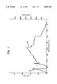
- FIG. 1 shows a graph (labelled 1C) illustrating the load deflection behavior of the present composite comprised of filaments in a zircon matrix, and another graph (labelled 1X) illustrating the load deflection behavior of a monolithic body of zircon; and
- FIG. 2 shows a graph (labelled 2A) illustrating the load-deflection behavior of the present composite comprised of filaments and whiskers in a zircon matrix, and another graph (labelled 2X) illustrating the load deflection behavior of a composite comprised of zircon and whiskers.
- the present process for producing a composite comprises:
- fibrous material includes fibers, filaments, continuous filaments, strands, bundles, whiskers, cloth, felt and a combination thereof.
- the fibrous material can be amorphous, crystalline or a mixture thereof.
- the crystalline fibrous material can be single crystal and/or polycrystalline.
- the fibrous material is a carbon-containing material which contains carbon in an amount of at least about 1% by weight, frequently at least about 5% by weight, of the fibrous material.
- the fibrous material is selected from the group consisting of elemental carbon, a SiC-containing material, boron nitride, silicon nitride, and a combination thereof.
- the SiC-containing material generally contains at least about 50% by weight of silicon and at least about 25% by weight of carbon, based on the weight of the fibrous material.
- Examples of SiC-containing materials are silicon carbide, Si--C--O, Si--C--O--N, Si--C--O---Metal and Si--C--O---N--Metal, where the Metal component can vary but frequently is Ti or Zr and wherein O, N and Metal are present generally in an amount of at least about 1% by weight of the fibrous material.
- elemental carbon includes all forms of elemental carbon including graphite.
- Reference herein to a fibrous material of silicon carbide includes, among others, presently available materials wherein silicon carbide envelops a core or substrate, and which generally are produced by chemical vapor deposition of silicon carbide on a core or substrate such as, for example, elemental carbon or tungsten.
- the fibrous material is stable at the temperature of the present process.
- the fibrous material has in air at ambient or room temperature, i.e. from about 20° C. to about 30° C., a minimum tensile strength of about 100,000 psi and a minimum tensile modulus of about 25 million psi.
- the fibrous material is provided substantially as a layer.
- the layer of fibrous material can be continuous or discontinuous and it contains sufficient spacing to permit production of the present composite. Specifically, there is sufficient spacing between fibers, filaments, strands, bundles, or whiskers to permit penetration thereof by the ceramic particulates to produce the present composite.
- the extent of the spacing in the layer of fibrous material is determined empirically and depends largely on the size of the ceramic particulates and the particular composite desired.
- the matrix-forming material is comprised of ceramic particulates. These particulates are inorganic, crystalline, and in the present process, they are consolidated, i.e. they undergo solid state sintering, to produce the present solid composite.
- the matrix-forming particulates are comprised of an oxide-based ceramic such as, for example, mullite or zircon.
- the particulates are of a size which can penetrate the spaces in the layer of fibrous material sufficiently to produce the present composite.
- the ceramic particles have a specific surface area ranging from about 0.2 to about 10 meters 2 per gram, and frequently, ranging from about 2 to about 4 meters 2 per gram.
- the matrix-forming material, or matrix in the composite has a thermal expansion coefficient ranging from lower than that of the fibrous material to less than about 15% higher than that of the fibrous material.
- a matrix-forming material with a thermal expansion coefficient about 15% or more higher than that of the fibrous material may result in a matrix with significantly deleterious cracks which would render the composite substantially less useful.
- the matrix-forming material, or matrix has a thermal expansion coefficient ranging from less than to about the same as that of the fibrous material.
- the components forming the composite i.e. fibrous material and matrix-forming material, are solid. Also, there is no significant amount of reaction product formed, or no reaction product detectable by scanning electron microscopy, between the ceramic matrix and fibrous material.
- a slurry of the ceramic particulates and organic binding material is formed.
- a slurry of the ceramic particulates, the present fibrous material in the form of whiskers, preferably crystalline inorganic whiskers, and organic binding material is formed.
- the whiskers are less than about 50 microns in length and less than about 10 microns in diameter.
- the whiskers in the slurry range up to about 50% or from about 1% to about 30%, or from about 20% to about 30%, by volume of the matrix-forming material.
- the whiskers in the slurry may or may not penetrate the spaces in the layer of fibrous material depending largely on the size of the whiskers.
- the whiskers introduced by the slurry are comprised of silicon carbide or silicon nitride.
- the organic binding material used in the present process bonds the ceramic particulates and fibrous material together and enables formation of tape of desired thickness and solids content.
- solids content it is meant herein the content of matrix-forming material and fibrous material.
- the organic binding material i.e. that component of the tape other than its solids content, thermally decomposes at an elevated temperature ranging to below about 800° C., generally from about 50° C. to below about 800° C., and preferably from about 100° C., to about 500° C., to gaseous product of decomposition which vaporizes away leaving no significant deleterious residue.
- the organic binding material is a thermoplastic material with a composition which can vary widely and which is well known in the art or can be determined empirically. Besides an organic polymeric binder it can include an organic plasticizer therefor to impart flexibility. The amount of plasticizer can vary widely depending largely on the particular binder used and the flexibility desired, but typically, it ranges up to about 50% by weight of the total organic content. Preferably the organic binding material is soluble in a volatile solvent.
- useful organic binders are polyvinyl acetates, polyamides, polyvinyl acrylates, polymethacrylates, polyvinyl alcohols, polyvinyl butyrals, and polystyrenes.
- the useful molecular weight of the binder is known in the art or can be determined empirically. Ordinarily, the organic binder has an average molecular weight at least sufficient to make it retain its shape at room temperature and generally such an average molecular weight ranges from about 20,000 to about 200,000, frequently from about 30,000 to about 100,000.
- plasticizers are dioctyl phthalate, dibutyl phthalate, diisodecyl glutarate, polyethylene glycol and glycerol trioleate.
- the matrix-forming particles and organic binding material along with any whiskers are admixed with a liquid medium to form a suspension or slurry which preferably is uniform or at least substantially uniform.
- a number of conventional techniques can be used to form the slurry.
- the components are milled in an organic solvent in which the organic material is soluble or at least partially soluble to produce a castable suspension or slurry, i.e. a slurry suitable for depositing on the layer of fibrous material to form a tape therewith.
- suitable solvents are methyl ethyl ketone, toluene and alcohol.
- the tape can be cast by a number of conventional techniques.
- the layer of fibrous material is deposited on a carrier from which the tape can be easily released such as Teflon.
- the slurry can be deposited on the layer of fibrous material to form a tape therewith of desired thickness and solids content which is determined empirically. Frequently, the slurry is cast on the layer of fibrous material by doctor blading.
- the cast tape is dried to evaporate the solvent therefrom to produce the present tape which is then removed from the carrier.
- organic binding material used in forming the slurry is determined empirically and depends largely on the amount and distribution of solids desired in the resulting tape. Generally, the organic binding material ranges from about 25% by volume to about 50% by volume of the solids content of the tape.
- the present tape or sheet can be as long and as wide as desired, and generally it is of uniform or substantially uniform thickness. Its thickness depends largely on the volume fraction of fibrous material which must be accommodated and the particular composite desired and is determinable empirically.
- the tape should be at least sufficiently thick to contain an amount of matrix-forming ceramic particulates and fibrous material to produce the desired composite. Generally, with increasing volume fractions of fibrous material, correspondingly smaller amounts of matrix-forming material would be required.
- the tape has a thickness ranging from about 25 microns (0.001 inch) to about 1300 microns (0.052 inch), frequently ranging from about 25 microns (0.005 inch) to about 1000 microns (0.040 inch), and more frequently ranging from about 250 microns (0.01 inch) to about 500 microns (0.02 inch).
- the fibrous material is comprised of filaments preferably with a diameter of at least about 50 microns.
- the diameter of the filament ranges from about 50 microns to about 250 microns, frequently from about 70 microns to about 200 microns, or from about 100 microns to about 150 microns.
- the filament is continuous and can be as long as desired. It has a minimum length of at least about 10 times its diameter, and generally, it is longer than about 1000 microns, or it is longer than about 2000 microns.
- the minimum diameter of the filament depends largely on the minimum spacing required between the filaments through which the matrix-forming particles must penetrate and is determined empirically. For a given volume fraction of filaments, as the diameter of the filament decreases, the total amount of space between filaments decreases making it more difficult for the ceramic particles to penetrate the space.
- a preform comprised of a layer of continuous filaments which are spaced from each other and which are parallel, or at least substantially parallel, to each other is used.
- the minimum space between the filaments is at least sufficient to enable the matrix-forming material to penetrate therebetween, and generally, it is at least about 50 microns, and frequently at least about 100 microns.
- the spacing between filaments in a single layer is substantially equivalent, or if desired, it can vary. Filament loading in the composite can be varied by changing the spacing between the filaments and/or tape thickness.
- the present invention enables the production of a composite with a high volume fraction of uniaxially aligned spaced continuous filaments.
- the preform of filaments can be produced by a number of conventional techniques.
- the filaments can be uniaxially aligned and spaced by placing them in a suitable device provided with grooves and the desired spacing.
- the layer of filaments can be lifted off the device with adhesive tape placed across both ends of the filaments.
- the slurry can then be deposited on the layer of filaments to produce a tape therewith. If desired, the taped end portions of the filaments can eventually be cut away from the laminated structure.
- a plurality of the tapes is assembled into a layered structure.
- the number of tapes used can vary widely depending largely on the particular composite desired.
- the tapes in the layered structure are at least substantially coextensive with each other, i.e. substantially a sandwich-type structure.
- a solution of the present organic binder in organic solvent is deposited, generally sprayed, on the faces of the tapes to be contacted with each other, dried to evaporate the solvent and leave a sticky film of organic binder to enhance adhesion.
- concentration of organic binder in solution can vary widely and generally ranges from about 1% by weight to about 10% by weight of the solution.
- the solution is sprayed on the face of the tape for a period of time, determinable empirically, so that on evaporation of the solvent sufficient sticky binder remains to significantly enhance adhesion or facilitate bonding of the tapes.
- drying is carried out in air at ambient temperature in less than a minute, and typically, in a few seconds.
- the deposited binder may be a continuous or discontinuous coating, and typically, 0.2 milligrams of sticky binder per square centimeter of surface is adequate.
- the layered structure is then laminated under a pressure and temperature determined empirically depending largely on the particular composition of the organic binding material to form a laminated structure.
- Lamination can be carried out in a conventional manner.
- Laminating temperature should be below the temperature at which there is decomposition, or significant decomposition, of organic binding material and generally, an elevated temperature below 150° C. is useful and there is no significant advantage in using higher temperatures.
- the lamination temperature ranges from about 35° C. to about 95° C. and the pressure ranges from about 500 psi to about 3000 psi.
- lamination time ranges from about 1/2 to about 5 minutes. Also, generally, lamination is carried out in air.
- the laminated structure can be cut to desired dimensions by suitable means such as a diamond saw.
- the laminated structure is heated to thermally decompose the organic binding material therein producing a porous structure comprised of the fibrous material and matrix-forming material.
- the rate of heating depends largely on the thickness of the sample and on furnace characteristics. At a firing temperature ranging up to about 500° C., a slower heating rate is desirable because of the larger amounts of gas generated at these temperatures by the decomposition of the organic binding material.
- the heating rate for a sample of less than about 6 millimeters in thickness can range from about 15° C. per hour to about 30° C. per hour. At a temperature of less than about 800° C., thermal decomposition is completed leaving no significant deleterious residue.
- Thermal decomposition can be carried out in any atmosphere, preferably at or below atmospheric pressure, which has no significant deleterious effect on the sample such as, for example, argon.
- thermal decomposition is carried out in a partial vacuum to aid in removal of gases.
- the resulting porous structure is hot pressed at a sufficient temperature under a sufficient pressure for a sufficient period of time to consolidate the structure to produce the present composite.
- the particular pressure, temperature and time are determinable empirically and are interdependent.
- Hot pressing temperature can vary depending largely on the characteristics of the matrix-forming material, the applied pressure and hot pressing time. Generally under higher applied pressures and longer times, lower hot pressing temperatures can be used. Likewise, under lower applied pressures and shorter times, higher hot pressing temperatures would be used.
- the hot pressing temperature is at least about 1400° C., generally ranging from about 1400° C. to about 1700° C., frequently from about 500° C. to about 1650° C., and more frequently from about 1550° C. to about 1600° C.
- temperatures below about 1400° C. are likely to produce a composite having a porosity greater than about 5% whereas temperatures above about 1700° C. may coarsen the grains in the product and not effect density.
- hot pressing pressure ranges from higher than about 100 psi to a maximum pressure which is limited by the creep of the sample, i.e. there should be no significant deformation by creep of the sample. Frequently, hot pressing pressure ranges from about 1000 psi or about 2000 psi to about 8000 psi. It is advantageous to use a pressure close to the maximum available because the application of such high pressure makes it possible to keep the pressing temperature low enough to control grain growth. Generally, hot pressing is carried out in a period of time ranging up to about 30 minutes and longer periods of time usually do not provide any significant advantage.
- Hot pressing is carried out in a non-oxidizing atmosphere. More particularly, it is carried out in a protective atmosphere in which the sample is substantially inert, i.e. an atmosphere which has no significant deleterious effect thereon.
- a protective atmosphere in which the sample is substantially inert, i.e. an atmosphere which has no significant deleterious effect thereon.
- Representative of the hot pressing atmospheres is nitrogen, argon, helium or a vacuum.
- the hot pressing atmosphere generally can range from a substantial vacuum to about atmospheric pressure.
- the present composite is comprised of ceramic matrix and fibrous material.
- the ceramic matrix is continuous and interconnecting. It is distributed in the fibrous material and generally it is space filling or substantially completely space filling. Generally, the matrix is in direct contact with more than 70% of the surface area of the fibrous material. Frequently, the ceramic matrix coats or envelops each fiber, filament, strand, bundle or whisker of the fibrous material sufficiently to be in direct contact with more than 80%, preferably more than 90%, more preferably more than 99%, of the surface area of the fibrous material in the composite.
- the ceramic matrix is present in the composite in an amount of at least about 30% by volume of the composite.
- the matrix is comprised of a solid state sintered polycrystalline phase.
- the ceramic matrix phase has an average grain size of less than about 100 microns, or less than about 50 microns, or less than about 20 microns, and most preferably less than about 10 microns.
- the fibrous material comprises at least about 10% by volume of the composite. Generally, the fibrous material ranges from about 10% by volume to about 70% by volume, frequently from about 20% by volume to about 60% by volume, or from about 30% by volume to about 50% by volume, of the composite.
- the present composite is comprised of a plurality of layers of fibrous material in the ceramic matrix wherein the fibrous layers are substantially parallel to each other and separated from each other by ceramic matrix.
- the ceramic matrix is distributed in each layer of fibrous material generally significantly or substantially uniformly.
- the ceramic matrix may contain whiskers, which had been incorporated by the slurry, which may range up to about 50%, frequently from about 1% to about 30%, or from about 20% to about 30%, by volume of the ceramic matrix.
- the whiskers are contained in the ceramic matrix between layers of fibrous material, i.e. at least between two layers of fibrous material.
- the whiskers may also be detected within the fibrous layer depending largely on shape and size of the whiskers, spacing contained in the fibrous layer, any difference in composition between the fibrous layer and whiskers and particle size of the ceramic.
- the composite contains a plurality of layers of filaments, there is no contact between the layers and they are separated by ceramic matrix.
- each layer more than 99% by volume of the filaments, and preferably all or substantially all of the filaments, are spaced from each other and parallel or at least substantially parallel, to each other. More than 99% by volume or substantially all of the filaments in each layer are aligned, or substantially aligned, in a single plane. Any misalignment of the filaments should not significantly degrade the mechanical properties of the composite.
- more than 99% or substantially all of the surface area of the filaments is in direct contact with the ceramic matrix.
- whiskers may be present up to about 50% by volume of the ceramic matrix. The filaments prevent brittle fracture of the composite at room temperature.
- brittle fracture of a composite it is meant herein that the entire composite cracks apart at the plane of fracture.
- this embodiment of the composite exhibits filament pull-out on fracture at room temperature.
- this composite cracks open generally at least about 10% by volume, frequently at least about 30% or 50% by volume, of the filaments, and preferably all of the filaments, pull out and do not break at the plane of fracture at room temperature.
- the present composite can be produced directly in a wide range of sizes. For example, it can be as long or as thick as desired.
- the present composite has a porosity of less than about 10%, preferably less than about 5%, more preferably less than about 1%, by volume of the composite. Most preferably, the composite is void- or pore- free, or has no significant porosity, or has no porosity detectable by scanning electron microscopy. Generally, any voids or pores in the composites are less than about 70 microns, preferably less than about 50 microns or less than about 10 microns, and generally they are distributed in the composite.
- the present composite has a wide range of applications depending largely on its particular composition. For example, it is useful as a wear resistant part, acoustical part or high-temperature structural component.
- filaments of silicon carbide produced by a chemical vapor deposition process and sold under the trademark AVCO SCS-6 were used. These filaments had a 35 micron carbon core on which silicon carbide was deposited to an overall diameter of about 145 microns.
- the outside surface of the filaments consisted of two layers of pyrolytic carbon and carbon-silicon, with overall thickness of about 3 microns. In air at room temperature these filaments have a tensile strength of about 500 thousand psi and a tensile modulus of about 60 million psi. These filaments have an average thermal expansion coefficient of less than about 5.0 ⁇ 10 -6 in/in-° C.
- the filaments were cut to a length of about 2 inches and were uniaxially aligned by placing them in a device for aligning filaments and maintaining the required spacing between them.
- This device was made from a copper foil laminated on a printed circuit board which was etched by the photolithographic technique in such a way as to produce parallel grooves about 0.006 inch diameter, 0.004 inch deep, and 0.008 inch apart (center-to-center).
- the filaments were placed on this device and a simple scoop of the filaments using a straight edge led to filling of each of the grooves with a filament. This resulted in a single layer of uniformly spaced filaments which was lifted off the board by putting adhesive tapes across each end portion of the filament layer. The adhesive tapes were sufficient to maintain the alignment and spacing between the filaments in the layer.
- Several such pre-formed layers of filaments were produced in which the filaments were substantially parallel and spaced about 100 microns from each other.
- the zircon powder had an average size of about 0.5 microns.
- ambient temperature herein it is meant room temperature, i.e. from about 20° C. to about 30° C.
- the organic binding material was comprised of commercially available organic binder comprised of polyvinylbutyral (average molecular weight of about 32,000) and commercially available liquid plasticizer comprised of polyunsaturated hydroxylated low-molecular weight organic polymers. Specifically, in Example 1, the organic binding material was comprised of 8.75 grams of polyvinylbutyral and 7.9 grams of liquid plasticizer, and in Example 2 it was comprised of 9.4 grams of polyvinylbutyral and 11.0 grams of liquid plasticizer.
- Hot pressing was carried out in a 2 inch inner diameter 2 inch inner length cylindrical die in an atmosphere of flowing nitrogen which was at about atmospheric pressure.
- Standard techniques were used to characterize the hot pressed composite for density, microstructure and mechanical properties.
- Each pre-formed layer of filaments was deposited on a Mylar sheet, the slurry was deposited on the filaments using a doctor blade, the cast tape was then dried in air at room temperature and atmospheric pressure to remove the solvent, and the resulting tape was stripped from the Mylar sheet.
- the tape was about 6 inches wide and had a substantially uniform thickness of about 0.010 inch. Zircon powder was distributed therein substantially uniformly.
- the tape was cut to the length and width of the aligned layer of filaments. A number of such tapes were produced.
- a layered sandwich-type structure was formed comprised of six layers of tape.
- the faces of the tapes which were to be contacted with each other were sprayed with an organic solution of binder, dried for a few seconds in air at room temperature leaving a coating of sticky organic binder.
- a solution comprised of 3 weight % of commercially available polyvinylbutyral (average molecular weight of about 32,000), 39 weight % toluene, 9.5 weight % acetone, 39 weight % xylene and 9.5 weight % ethanol was used.
- the solution was sprayed on the faces of the tapes for a sufficient time so that upon evaporation of the solvent there remained about 0.2 milligrams of sticky organic binder per square centimeter of surface.
- the resulting layered structure was laminated in air in a laminating press at about 93° C. under a pressure of about 1000 psi for about 1 minute. At lamination temperature and pressure, the tapes were plastic resulting in filling of the void space between and around the filaments.
- the laminated structure was sliced perpendicular to the filament axis into bar-shaped samples (1.25 inch ⁇ 0.3 inch ⁇ 0.15 inch) using a diamond saw. Examination of a cross-section showed uniform spacing between the filaments as well as between the layers of filaments.
- the samples were placed in a vacuum oven for removing the organic binding material wherein the vacuum was typically about 20 millitorr.
- the burnout cycle was comprised of heating the furnace at a rate of 30° C. per hour to 500° C., a five hour hold at 500° C. and a cooldown to room temperature at a rate of 200° C. per hour. This led to complete removal of the organic binding matter from the laminated structure which resulted in a porous structure comprised of zircon powder and filaments.
- Each of the porous bar-shaped structures was placed in a graphite die and hot-pressed at about 1580° C. Each sample was heated at a rate of approximately 100° C. per minute to the maximum hot pressing temperature under a pressure of 3500 psi applied for consolidation. The consolidation was monitored by plunger displacement and complete densification occurred within 30 minutes after the onset of densification. After hot-pressing, the sample was furnace cooled to room temperature and removed from the die.
- the hot pressed samples i.e. composites, were characterized and are illustrated in Table I.
- the cross section (perpendicular to filament axis) of one of the composites was examined. It showed uniform spacing between the filaments as well as uniform spacing between layers of filaments which the present composite can have. It also showed that each layer of filaments was maintained in a substantially single plane. In addition, it showed a fully dense zircon matrix surrounding each individual filament and in direct contact therewith. The density of this composite was 4.38 g/cc, in line with fully dense zircon matrix material containing about 25 volume % filaments. No porosity was detected in the composite by microscopy. Zircon has an average thermal expansion coefficient of about 4.8 ⁇ 10 -6 in/in-° C. which is close to that of the silicon carbide filaments.
- FIG. 1 shows a load deflection curve for the composite of Example 1C. It can be seen that this composite showed toughened ceramic-like behavior.
- the load-deflection curve shows that at the onset of matrix cracking, the load carrying capability of the composite was maintained for a while reaching an ultimate strength of 53,700 psi (370 MPa) beyond which the composite showed substantial but not complete failure.
- Example 1X in Table I For comparison, six tapes of zircon powder alone and organic binder were produced, formed into a layered structure, laminated, heated to remove organic binder, and hot pressed in substantially the same manner as the sample of Example 1C to produce a body (Example 1X in Table I) of substantially the same size and density which was broken in substantially the same manner. Its load deflection curve is also shown in FIG. 1. It fractured in a brittle manner at 35,400 psi (244 MPa).
- Zircon powder and silicon carbide whiskers were used instead of zircon alone in forming the slurry. Specifically, 200 grams of zircon powder and 35 grams of silicon carbide whiskers were mixed by hand. To this 3 grams of organic binder, 83 grams of toluene, and 38 grams of methyl isobutyl ketone were added. This mixture was mixed for 20 minutes using zirconia grinding media on a ball mill. Additional 17.4 grams of binder and 0.2 gram of silicone oil were added to the slurry and the contents were mixed for one hour on a ball mill. The slurry was deaired and cast over the deposited filaments on a mylar sheet using a doctor blade.
- the dried tape had a thickness of about 0.010 inch.
- FIG. 2 shows a load deflection curve for the composite of Example 2A. It can be seen that this composite showed toughened ceramic-like behavior.
- the load-deflection curve shows the onset of matrix cracking followed by a significant rise in the load carrying capability of the composite. An ultimate strength of 461 MPa (66,900 psi) was reached beyond which the composite showed substantial but not complete failure.
Abstract
Description
                                  TABLE I
__________________________________________________________________________
              Filament
          Tape
              Containing
                    Composite Characteristics
   Solids Thick-
              Tapes In
                    Hot Pressing      Avg.
                                          Fracture
                                               Fracture
   in     ness
              Layered
                    Temperature
                           Density
                                Filaments
                                      Grain
                                          Strength
                                               Strain
Ex.
   Slurry (inch)
              Structure
                    (°C.)
                           g/cc Vol. %
                                      Size
                                          (MPa)
                                               (%)
__________________________________________________________________________
1A zircon 0.010
              6     1560   4.35 25    <5 μm
                                          560  1.1
1B "      0.010
              6     1560   4.34 25    "   540  0.9
1C "      0.010
              6     1560   4.38 25    "   370  0.87
1X "      0.012
              none  1560   4.4   0    "   244  0.09
2A zircon +
          0.010
              6     1600   3.67 25    "   461  0.72
   SiC whiskers
2B zircon +
          0.010
              6     1600   3.61 25    "   453  0.80
   SiC whiskers
2C zircon +
          0.010
              6     1600   3.61 25    "   367  0.70
   SiC whiskers
2X zircon +
          0.010
              none  1600   3.79  0    "   306  0.10
   SiC whiskers
__________________________________________________________________________
Claims (29)
Priority Applications (1)
| Application Number | Priority Date | Filing Date | Title |
|---|---|---|---|
| US07/260,201 US5407734A (en) | 1988-10-20 | 1988-10-20 | Fiber-containing composite |
Applications Claiming Priority (1)
| Application Number | Priority Date | Filing Date | Title |
|---|---|---|---|
| US07/260,201 US5407734A (en) | 1988-10-20 | 1988-10-20 | Fiber-containing composite |
Publications (1)
| Publication Number | Publication Date |
|---|---|
| US5407734A true US5407734A (en) | 1995-04-18 |
Family
ID=22988194
Family Applications (1)
| Application Number | Title | Priority Date | Filing Date |
|---|---|---|---|
| US07/260,201 Expired - Fee Related US5407734A (en) | 1988-10-20 | 1988-10-20 | Fiber-containing composite |
Country Status (1)
| Country | Link |
|---|---|
| US (1) | US5407734A (en) |
Cited By (12)
| Publication number | Priority date | Publication date | Assignee | Title |
|---|---|---|---|---|
| US5654094A (en) * | 1989-07-07 | 1997-08-05 | Alliedsignal Inc. | Metal carbide fibers |
| US5876537A (en) * | 1997-01-23 | 1999-03-02 | Mcdermott Technology, Inc. | Method of making a continuous ceramic fiber composite hot gas filter |
| US6155432A (en) * | 1999-02-05 | 2000-12-05 | Hitco Carbon Composites, Inc. | High performance filters based on inorganic fibers and inorganic fiber whiskers |
| US6277440B1 (en) | 1998-11-23 | 2001-08-21 | Msnw, Inc. | Preparation of ceramic matrix composites by infiltration of fibrous preforms with fluids or slurries and subsequent pyrolysis |
| US20030022783A1 (en) * | 2001-07-30 | 2003-01-30 | Dichiara Robert A. | Oxide based ceramic matrix composites |
| US20040192534A1 (en) * | 2000-09-29 | 2004-09-30 | Nixon Thomas Dwayne | Boron carbide based ceramic matrix composites |
| US6855428B2 (en) | 2000-09-29 | 2005-02-15 | B. F. Goodrich Company | Boron carbide based ceramic matrix composites |
| US20050181193A1 (en) * | 2003-12-04 | 2005-08-18 | Ilka Lenke | Porous fiber-ceramic composite |
| EP1566370A2 (en) * | 2004-02-23 | 2005-08-24 | General Electric Company | Thermo-mechanical property enhancement plies for CVI/SiC ceramic matrix composite laminates |
| WO2007061398A1 (en) * | 2005-07-25 | 2007-05-31 | Siemens Power Generation, Inc. | Method of forming cmc component |
| WO2017125947A1 (en) * | 2016-01-19 | 2017-07-27 | Council Of Scientific & Industrial Research | A thermo-laminated multilayered zircon based high temperature co-fired ceramic (htcc) tape and the process thereof |
| US10233124B2 (en) * | 2013-03-12 | 2019-03-19 | Hug Engineering Ag | Method for producing a molded article and molded article |
Citations (13)
| Publication number | Priority date | Publication date | Assignee | Title |
|---|---|---|---|---|
| US4636480A (en) * | 1985-01-18 | 1987-01-13 | General Electric Company | Composite by infiltration |
| US4640899A (en) * | 1985-06-21 | 1987-02-03 | General Electric Company | Mullite matrix composite |
| US4642271A (en) * | 1985-02-11 | 1987-02-10 | The United States Of America As Represented By The Secretary Of The Navy | BN coating of ceramic fibers for ceramic fiber composites |
| US4689188A (en) * | 1986-07-16 | 1987-08-25 | The United States Of America As Represented By The Administrator Of The National Aeronautics And Space Administration | Method of preparing fiber reinforced ceramic material |
| US4725567A (en) * | 1985-12-02 | 1988-02-16 | General Electric Company | Composite by infiltration |
| US4737476A (en) * | 1986-05-23 | 1988-04-12 | General Electric Company | Composite by infiltration |
| US4769349A (en) * | 1986-12-03 | 1988-09-06 | General Electric Company | Ceramic fiber casting |
| US4781993A (en) * | 1986-07-16 | 1988-11-01 | The United States Of America As Represented By The Administrator Of The National Aeronautics And Space Administration | Fiber reinforced ceramic material |
| US4788162A (en) * | 1985-12-23 | 1988-11-29 | General Electric Company | Composite by compression |
| US4810442A (en) * | 1986-12-29 | 1989-03-07 | General Electric Company | Method of forming fiber- and filament-containing ceramic preform and composite |
| US4886682A (en) * | 1987-12-14 | 1989-12-12 | General Electric Company | Process for producing a filament-containing composite in a ceramic matrix |
| US4889686A (en) * | 1989-02-17 | 1989-12-26 | General Electric Company | Composite containing coated fibrous material |
| US4915760A (en) * | 1988-10-26 | 1990-04-10 | General Electric Company | Method of producing a coated fiber-containing composite |
-
1988
- 1988-10-20 US US07/260,201 patent/US5407734A/en not_active Expired - Fee Related
Patent Citations (13)
| Publication number | Priority date | Publication date | Assignee | Title |
|---|---|---|---|---|
| US4636480A (en) * | 1985-01-18 | 1987-01-13 | General Electric Company | Composite by infiltration |
| US4642271A (en) * | 1985-02-11 | 1987-02-10 | The United States Of America As Represented By The Secretary Of The Navy | BN coating of ceramic fibers for ceramic fiber composites |
| US4640899A (en) * | 1985-06-21 | 1987-02-03 | General Electric Company | Mullite matrix composite |
| US4725567A (en) * | 1985-12-02 | 1988-02-16 | General Electric Company | Composite by infiltration |
| US4788162A (en) * | 1985-12-23 | 1988-11-29 | General Electric Company | Composite by compression |
| US4737476A (en) * | 1986-05-23 | 1988-04-12 | General Electric Company | Composite by infiltration |
| US4689188A (en) * | 1986-07-16 | 1987-08-25 | The United States Of America As Represented By The Administrator Of The National Aeronautics And Space Administration | Method of preparing fiber reinforced ceramic material |
| US4781993A (en) * | 1986-07-16 | 1988-11-01 | The United States Of America As Represented By The Administrator Of The National Aeronautics And Space Administration | Fiber reinforced ceramic material |
| US4769349A (en) * | 1986-12-03 | 1988-09-06 | General Electric Company | Ceramic fiber casting |
| US4810442A (en) * | 1986-12-29 | 1989-03-07 | General Electric Company | Method of forming fiber- and filament-containing ceramic preform and composite |
| US4886682A (en) * | 1987-12-14 | 1989-12-12 | General Electric Company | Process for producing a filament-containing composite in a ceramic matrix |
| US4915760A (en) * | 1988-10-26 | 1990-04-10 | General Electric Company | Method of producing a coated fiber-containing composite |
| US4889686A (en) * | 1989-02-17 | 1989-12-26 | General Electric Company | Composite containing coated fibrous material |
Non-Patent Citations (9)
| Title |
|---|
| Abstract (20 C 87C) Effect of Boron Nitride Coating on Fiber Matrix Interactions , RNSingh & MKBrun, Ceramics Bulletin, vol. 65, No. 11 (Nov. 1986). * |
| Abstract (20-C-87C) "Effect of Boron Nitride Coating on Fiber-Matrix Interactions", RNSingh & MKBrun, Ceramics Bulletin, vol. 65, No. 11 (Nov. 1986). |
| MKBrun & RNSingh, Effect of Thermal Expansion Mismatch and Fiber Coating on the Fiber/Matrix Interfacial Shear Stress in CMCs (87 CRD 139)(Jul. 1987) 13 pages. * |
| RNSingh & ARGaddipati, "Mechanical Properties of a Uniaxially REinforced Mullite-Silicon Carbide Composite" (87 CRD 120)(Jun. 1987) 14 pages. |
| RNSingh & ARGaddipati, Mechanical Properties of a Uniaxially REinforced Mullite Silicon Carbide Composite (87 CRD 120)(Jun. 1987) 14 pages. * |
| RNSingh & MKBrun, "Effect of Boron Nitride Coating on Fiber-Matrix Interactions" (87 CRD 051)(Apr. 1987) 12 pages. |
| RNSingh & MKBrun, Effect of Boron Nitride Coating on Fiber Matrix Interactions (87 CRD 051)(Apr. 1987) 12 pages. * |
| RNSingh, "Role of Fiber-Matrix Interfacial Shear Stress on the Toughness of Reinforced Oxide Matrix Composites" (88 CRD 129) (Apr. 1988) 9 pages. |
| RNSingh, Role of Fiber Matrix Interfacial Shear Stress on the Toughness of Reinforced Oxide Matrix Composites (88 CRD 129) (Apr. 1988) 9 pages. * |
Cited By (22)
| Publication number | Priority date | Publication date | Assignee | Title |
|---|---|---|---|---|
| US5654094A (en) * | 1989-07-07 | 1997-08-05 | Alliedsignal Inc. | Metal carbide fibers |
| US5876537A (en) * | 1997-01-23 | 1999-03-02 | Mcdermott Technology, Inc. | Method of making a continuous ceramic fiber composite hot gas filter |
| US6277440B1 (en) | 1998-11-23 | 2001-08-21 | Msnw, Inc. | Preparation of ceramic matrix composites by infiltration of fibrous preforms with fluids or slurries and subsequent pyrolysis |
| US6155432A (en) * | 1999-02-05 | 2000-12-05 | Hitco Carbon Composites, Inc. | High performance filters based on inorganic fibers and inorganic fiber whiskers |
| US6321915B1 (en) | 1999-02-05 | 2001-11-27 | Hitco Carbon Composites, Inc. | High performance filters based on inorganic fibers and inorganic fiber whiskers |
| US6402951B1 (en) | 1999-02-05 | 2002-06-11 | Hitco Carbon Composites, Inc. | Composition based on a blend of inorganic fibers and inorganic fiber whiskers |
| US20040192534A1 (en) * | 2000-09-29 | 2004-09-30 | Nixon Thomas Dwayne | Boron carbide based ceramic matrix composites |
| US6855428B2 (en) | 2000-09-29 | 2005-02-15 | B. F. Goodrich Company | Boron carbide based ceramic matrix composites |
| US7378362B2 (en) | 2000-09-29 | 2008-05-27 | Goodrich Corporation | Boron carbide based ceramic matrix composites |
| US20050218565A1 (en) * | 2001-07-30 | 2005-10-06 | Dichiara Robert A Jr | Oxide based ceramic matrix composites |
| US20030022783A1 (en) * | 2001-07-30 | 2003-01-30 | Dichiara Robert A. | Oxide based ceramic matrix composites |
| WO2004108631A2 (en) | 2003-06-02 | 2004-12-16 | Goodrich Corporation | Boron carbide based ceramic matrix composites |
| US20050181193A1 (en) * | 2003-12-04 | 2005-08-18 | Ilka Lenke | Porous fiber-ceramic composite |
| US7459110B2 (en) * | 2003-12-04 | 2008-12-02 | Ceramtec Ag | Porous fiber-ceramic composite |
| US20050186878A1 (en) * | 2004-02-23 | 2005-08-25 | General Electric Company | Thermo-mechanical property enhancement plies for CVI/SiC ceramic matrix composite laminates |
| EP1566370A2 (en) * | 2004-02-23 | 2005-08-24 | General Electric Company | Thermo-mechanical property enhancement plies for CVI/SiC ceramic matrix composite laminates |
| EP1566370A3 (en) * | 2004-02-23 | 2010-11-03 | General Electric Company | Thermo-mechanical property enhancement plies for CVI/SiC ceramic matrix composite laminates |
| WO2007061398A1 (en) * | 2005-07-25 | 2007-05-31 | Siemens Power Generation, Inc. | Method of forming cmc component |
| US20080116614A1 (en) * | 2005-07-25 | 2008-05-22 | Siemens Power Generation, Inc. | Method of Forming Cmc Component |
| US7550107B2 (en) | 2005-07-25 | 2009-06-23 | Siemens Energy, Inc. | Method of forming CMC component |
| US10233124B2 (en) * | 2013-03-12 | 2019-03-19 | Hug Engineering Ag | Method for producing a molded article and molded article |
| WO2017125947A1 (en) * | 2016-01-19 | 2017-07-27 | Council Of Scientific & Industrial Research | A thermo-laminated multilayered zircon based high temperature co-fired ceramic (htcc) tape and the process thereof |
Similar Documents
| Publication | Publication Date | Title |
|---|---|---|
| US5160676A (en) | Fibrous material-containing composite | |
| US5336350A (en) | Process for making composite containing fibrous material | |
| US4889686A (en) | Composite containing coated fibrous material | |
| US4915760A (en) | Method of producing a coated fiber-containing composite | |
| US4981822A (en) | Composite containing coated fibrous material | |
| US5376427A (en) | Ceramic composite containing coated fibrous material | |
| US5067998A (en) | Fibrous material-containing composite | |
| US5330854A (en) | Filament-containing composite | |
| EP0564245B1 (en) | Protective coating with reactive interlayer on reinforcement in silicon carbide composite | |
| US6024898A (en) | Article and method for making complex shaped preform and silicon carbide composite by melt infiltration | |
| US6365233B1 (en) | Silicon-doped boron nitride coated fibers in silicon melt infiltrated composites | |
| US4885199A (en) | Fiber-reinforced silicon nitride composite ceramics | |
| EP0126017B1 (en) | High strength, thermally stable magnesium aluminosilicate glass-ceramic matrix-silicon carbide fibre composites | |
| JP3942199B2 (en) | Silicon carbide composite with fiber reinforcement coated with metal nitride | |
| US5407734A (en) | Fiber-containing composite | |
| US5211999A (en) | Laminated composite composed of fiber-reinforced ceramics and ceramics and method of producing same | |
| US4931311A (en) | Method of obtaining a filament-containing composite with a boron nitride coated matrix | |
| US4921822A (en) | Ceramic composite | |
| US5043303A (en) | Filament-containing composite | |
| US4410635A (en) | Discontinuous silicon carbide fiber reinforced ceramic composites | |
| JPH11292662A (en) | Fiber composite material and its use | |
| US5051301A (en) | Coated fiber-containing composite | |
| US4886682A (en) | Process for producing a filament-containing composite in a ceramic matrix | |
| EP1028099A1 (en) | Fibrous composite material and process for producing the same | |
| US5432253A (en) | Composite containing fibrous material |
Legal Events
| Date | Code | Title | Description |
|---|---|---|---|
| AS | Assignment |
Owner name: GENERAL ELECTRIC COMPANY, A NY CORP. Free format text: ASSIGNMENT OF ASSIGNORS INTEREST.;ASSIGNORS:SINGH, RAJ N.;GADDIPATI, ACHUTA R.;REEL/FRAME:004974/0674;SIGNING DATES FROM 19881013 TO 19881014 |
|
| FEPP | Fee payment procedure |
Free format text: PAYOR NUMBER ASSIGNED (ORIGINAL EVENT CODE: ASPN); ENTITY STATUS OF PATENT OWNER: LARGE ENTITY |
|
| FPAY | Fee payment |
Year of fee payment: 4 |
|
| REMI | Maintenance fee reminder mailed | ||
| LAPS | Lapse for failure to pay maintenance fees | ||
| LAPS | Lapse for failure to pay maintenance fees |
Free format text: PATENT EXPIRED FOR FAILURE TO PAY MAINTENANCE FEES (ORIGINAL EVENT CODE: EXP.); ENTITY STATUS OF PATENT OWNER: LARGE ENTITY |
|
| STCH | Information on status: patent discontinuation |
Free format text: PATENT EXPIRED DUE TO NONPAYMENT OF MAINTENANCE FEES UNDER 37 CFR 1.362 |
|
| FP | Lapsed due to failure to pay maintenance fee |
Effective date: 20030418 |