US5403320A - Bone milling guide apparatus and method - Google Patents
Bone milling guide apparatus and method Download PDFInfo
- Publication number
- US5403320A US5403320A US08/001,156 US115693A US5403320A US 5403320 A US5403320 A US 5403320A US 115693 A US115693 A US 115693A US 5403320 A US5403320 A US 5403320A
- Authority
- US
- United States
- Prior art keywords
- bone
- bore
- hollow body
- proximal end
- template
- Prior art date
- Legal status (The legal status is an assumption and is not a legal conclusion. Google has not performed a legal analysis and makes no representation as to the accuracy of the status listed.)
- Expired - Fee Related
Links
Images


Classifications
-
- A—HUMAN NECESSITIES
- A61—MEDICAL OR VETERINARY SCIENCE; HYGIENE
- A61B—DIAGNOSIS; SURGERY; IDENTIFICATION
- A61B17/00—Surgical instruments, devices or methods, e.g. tourniquets
- A61B17/16—Bone cutting, breaking or removal means other than saws, e.g. Osteoclasts; Drills or chisels for bones; Trepans
- A61B17/17—Guides or aligning means for drills, mills, pins or wires
- A61B17/1739—Guides or aligning means for drills, mills, pins or wires specially adapted for particular parts of the body
- A61B17/1742—Guides or aligning means for drills, mills, pins or wires specially adapted for particular parts of the body for the hip
- A61B17/175—Guides or aligning means for drills, mills, pins or wires specially adapted for particular parts of the body for the hip for preparing the femur for hip prosthesis insertion
Definitions
- This invention relates to hip stem prothesis apparatus and, more particularly, to a novel bone milling guide apparatus and method for the precision milling of a socket into the medullary cavity of the proximal femur of a patient, the socket thereby being prepared to receive a hip stem in a close-fitting relationship.
- Total hip replacement is one of the most remarkable advances in orthopedic surgery of this century. Since the first total hip joint replacement in 1962, significant advances have been made in both implant design and surgical technique. These improved devices and procedures offer new hope for patients crippled by degenerative arthritis, rheumatoid arthritis, or significant trauma to the hip. Diseases such as rheumatoid or osteo-arthritis generally result in degradation of the cartilage lining the acetabulum so that the ball of the femur rubs against the ilium. This rubbing action causes pain and further degradation of the remaining cartilage. Bone erosion causes the affected bones to attempt to compensate by reshaping, thus resulting in a misshapen joint which may eventually cease to function altogether.
- Total joint replacement can provide not only marked resolution of pain but significant functional improvement.
- approximately 250,000 successful total joint replacements are performed each year in the United States alone so that the replacement of a hip joint with an artificial implant or prosthetic device is now a routinely practiced surgical procedure.
- the long-term success rate following total hip replacement is excellent. It is estimated that over 90% of patients who have had total joint replacement are functioning well 12 years after surgery.
- a conventional hip prosthesis consists of an artificial femur head or ball mounted on the neck end of a stem with the ball being received in a prosthetic acetabular socket affixed to the ilium. The proximal end of the femur is removed and the stem is anchored in the medullary bone cavity.
- problems may infrequently develop following total joint replacement.
- the major potential complication of total joint replacement is infection. Pain following total joint replacement may also be due to mechanical loosening or breakage of the implant resulting in excessive motion between the prosthesis and the underlying bone.
- a second, total joint replacement or revision may be required. It is estimated that approximately five percent of all total joint replacements performed today are revisions of previous procedures.
- cemented arthroplasties are more forgiving than those designed for biologic fixation.
- a technically poor insertion of a porous-coated implant often results in fixation failure from the very start, with patient dissatisfaction as soon as weight bearing is allowed.
- a more suitable alternative that has evolved is that of a noncemented total hip replacement wherein the prosthesis is implanted in the absence of a cement.
- the potential for adequate bone ingrowth to create an enduring cementless implant fixation can be realized only if stable fixation is achieved from the start, particularly since fixation through bone ingrowth succeeds or fails within the first several months after implantation.
- the most important prerequisite for secure fixation and better physiological stress transfer between implant and osseous tissue is initial mechanical stability. Micromotion between the implant and the surrounding osseous tissue into which it is inserted must be minimal during the time when the intramedullary fracture callus adjacent the implant is differentiating into osseous tissue and maturing. This initial mechanical stability can only be achieved with careful preoperative planning, meticulous surgical technique and a wide selection of incrementally sized hip stem components.
- the medullary cavity of the femur is in the shape of an inverted, triangular pyramid at the top and a rod at the bottom.
- the first problem during preparation of the medullary cavity is to match the diaphysis which can be done by simple reaming to define the size of the stem.
- the second problem is to match the proximal end of the stem to the cortical bone.
- One approach is to provide the stem with a size range of sleeves which can be mounted to the stem in a locking relationship using a conventional Morse taper. Not only does the Morse taper allow one to use a preselected sleeve size, but it also accommodates placement of the triangular portion of the sleeve at a preselected angle to the neck of the stem.
- One bone milling device is disclosed by Frey et al (U.S. Pat. No. 4,777,942) and includes a milling instrument having a caliper that is inserted into the medullary cavity.
- a spindle is linked to the caliper at an angle and carries a milling cutter as well as a guide shoe at its distal end.
- the guide shoe slides within a guideway on the distal end of the caliper.
- the instrument guides the milling cutter to cut a circular arc corresponding to the boundary line between the spongiosa and cortical tissue in the region of the calcar arc.
- Forte discloses a combination of tools and methods used to prepare a socket in a femur for receiving a femoral prosthesis.
- a rasp is used to form a socket in the femur.
- a cutter is journaled to the rasp prior to its removal and is rotated to machine the surface of the calcar surrounding the socket.
- This invention is a bone milling template that is used to enable the surgeon to accurately and easily guide a bone miller in the preparation of the intramedullary cavity in the proximal end of the femur to receive the proximal end of a hip stem in close-fitting relationship.
- the template is demountably attached to a probe that is inserted into the bore created to receive the distal stem.
- the template accurately controls the movement of the bone miller in cutting a socket to receive the proximal end of the hip stem.
- Another object of this invention is to provide improvements in the method of preparing the proximal end of a femur to receive a hip stem.
- Another object of this invention is to provide a template apparatus for accurately guiding a bone miller in cutting the proximal end of a femur to receive a hip stem.
- Another object of this invention is to provide a template for a calcar miller wherein the position of the template is fixed by being partially inserted into a truncated cavity created in the intramedullary canal.
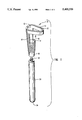
- FIG. 1 is an exploded, perspective view of the novel bone milling guide of this invention shown in the presence of a distal stem guide;
- FIG. 2 is a plan view of the bone milling guide
- FIG. 3 is a side elevation of the bone milling guide
- FIG. 4 is a cross sectional view of a proximal end of a femur shown in the process being drilled to receive a distal stem;
- FIG. 5 is a cross sectional view of the proximal end of the femur of FIG. 4 being reamed at its proximal end to receive the truncated portion of the bone milling guide;
- FIG. 6 is a cross sectional view of the proximal end of the femur of FIG. 5 with the bone milling guide in place in the medullary cavity and in the presence of a bone miller;
- FIG. 7 is a cross sectional view of the proximal end of the femur of FIG. 6 showing the intramedullary cavity prepared through the use of the bone milling guide of this invention.
- Bone consists of two basic types of tissue: hard or compact bone which is dense in texture, and soft or cancellous bone which consists of fibers and lamellae joined together to form a reticular network.
- the hard bone tissue is generally referred to as the cortical bone and constitutes the outer wall of the bone where it provides most of the overall strength of the bone.
- the thickness of the cortical bone varies at different positions along the length of the bone with the greatest thickness along the midpoint where the cross sectional area of the bone is the smallest.
- the cortical bone is thinner adjacent the ends where the bone flares outwardly to support the particular joint mechanism.
- cancellous bone forms the inner core of the bone with the major portions of cancellous bone being found adjacent the ends of the bone where the cross sectional area is the greatest and, correspondingly, where the cortical bone is the thinnest. It is currently believed that the cancellous bone in these regions contributes to the overall strength of the bone by transferring a portion of the applied stresses from the thin sections of cortical bone to the relatively large areas of thicker cortical bone located closer to the midsection of the bone. In these regions of stress transfer, the fibers making up the cancellous bone appear to have a regular equipotential-like arrangement wherein fibers intersect the internal surface of the cortical bone at spaced intervals of approximately one to two millimeters. It is believed that this arrangement, at least in part, is responsible for the efficient transfer of applied stress from one part of the cortical bone to another.
- the novel bone milling guide of this invention is shown generally at 10 and includes a template 12 extending from an upper edge of a hollow body 14.
- Hollow body 14 is configured with a vertical sidewall 13 formed with an external profile having a downwardly oriented taper as a portion of a truncated, right circular cone, the external profile of which closely approximate the shoulder region of the hip stem prosthesis (not shown) to be inserted in the intramedullary cavity 82 (FIG. 7).
- One side of hollow body 14 opposite vertical sidewall 13 is open as an opening 18 to expose the adjacent cancellous bone 63 (FIG. 6) to bone miller 50 (FIG. 6) as will be described more fully hereinafter.
- hollow body 14 has a coaxial cavity 15 configured as a downwardly tapered cavity terminating in a socket 16.
- the basal end of hollow body 14 terminates in a short, cylindrical base 19 which serves as a mounting surface for a guide 30 releasably mounted to hollow body 14.
- Template 12 extends outwardly from one side of the upper edge of hollow body 14 and is configured with a generally tapered, lozenge shape as shown in the plan view of FIG. 2.
- Template 12 includes an inwardly sloped inner face 20, the slope of which corresponds to an imaginary line 11 (FIG. 3) extending between inner face 20 and a rim 17 forming a face of socket 16 located coaxially in the base of hollow body 14.
- Template 12 extends outwardly and orthogonally to the axis of hollow body 14.
- the inner face of template 12 is provided with an inwardly-sloped surface 20, the slope of which corresponds to an imaginary surface extending upwardly from a rim 17 of socket 16.
- the region defined by the imaginary surface extending between sloped surface 20 and rim 17 is designated by cutout region 18.
- Cutout region 18 represents the portion of cancellous bone 63 (FIGS. 4-6) to be removed by a bone miller 50 (FIG. 5) as will be discussed more fully hereinafter.
- Guide 30 has a threaded, coaxial boss 32 at a proximal end and is configured to be threadedly engaged to hollow body 14 at base 19 and includes a rounded tip 34 at a distal end.
- Guide 30 is adapted to be releasably mounted to base 19 in a coaxial relationship with hollow body 14 by threaded boss 32 being threadedly engaged in a corresponding threaded bore 24.
- Guide 30 is configured to be inserted into a hole 65 (FIGS. 4-6) drilled into the intramedullary canal 66 of bone 60.
- Guide 30 has a smooth, cylindrical profile and is designed to slidingly engage the cancellous bone 63 forming the sidewall of bore 65 drilled therein.
- a bone 60 is shown schematically and in a cross sectional view with the ball portion (not shown) removed leaving a major portion of the greater trochanter 68 intact.
- the calcar region 62 is shown cut horizontally across the end of bone 60 which includes both cortical bone 64 and cancellous bone 63.
- Hole 65 is drilled into intramedullary canal 66 according to conventional techniques using a drill 70.
- the diameter and length of drill 70 are selected by the surgeon (not shown) so as to provide the appropriate size of hole 65 to receive the guide 30 (FIGS. 1 and 6) and pilot 74 (FIG. 5) prior to insertion of the distal stem of a hip stem prosthesis (not shown).
- hole 65 is shown as having been completed in cancellous bone 63 and a reamer 72 has been used to cut into cancellous bone 63 to prepare a cavity 80 in the same for insertion of bone milling guide 10 (FIGS. 1-3 and 6) as will be discussed in reference to FIG. 6.
- Reamer 72 is a conventional reamer having a frustoconical profile and is adapted to have a distal pilot 74 releasably affixed thereto.
- the external profile of reamer 72 is configured to conform to the external profile of hollow body 14 (FIGS. 1-3 and 6).
- Distal pilot 74 is inserted into hole 65 so as to control reamer 72 in reaming the frustoconical portion of cancellous bone 63.
- Distal pilot 74 is essentially identical to guide 30.
- bone milling guide 10 has been inserted into a cavity 80 created by reamer 72 (FIG. 5) in cancellous bone 63.
- Bone milling guide 10 is directed into cavity 80 by guide 30 being releasably secured to bone milling guide 10 and inserted into hole 65.
- Template 12 is held an incremental distance above the cortical bone 64 surrounding calcar region 62.
- bone milling guide 10 is now ready to receive therein bone miller 50.
- Bone miller 50 has a rounded tip 52, a milling surface 54, and an upper, guide follower 56.
- Cutout region 18 shown in FIG. 1 is now seen as a segment of cancellous bone 63 residing between cavity 80 and a dashed line 11 extending between rim 17 and sloped surface 20 on template 12.
- Cutout region 18 represents the segment of cancellous bone 63 to be removed by a bone miller 50.
- Bone miller 50 is inserted downwardly into bone milling guide 10 along the axis of cavity 15 until rounded tip 52 is received in socket 16. Bone miller 50 is then moved in an arcuate path with guide follower 56 following the profile defined by sloped surface 20 of template 12 while rounded tip 52 is held in socket 16. The movement of bone miller 50 in this arcuate path allows milling surface 54 to remove all of cancellous bone 63 in cutout region 18 providing cavity 80 with an enlarged cavity 82 as defined by dashed line 19 and also as shown in FIG. 7.
- hole 65 and cavity 82 are prepared quickly and accurately in comparison with the prior art techniques and, more importantly, with a far superior degree of precision.
- drill 70 is directed along the axis of the intramedullary canal 66 leaving hole 65 therein.
- drill 70 removes the cancellous bone 63 to preclude fragments thereof from becoming compacted in the bottom of hole 65.
- Guide 74 is mounted on the basal end of reamer 72 and directed into hole 65.
- the diameter of guide 74 is incrementally smaller than the diameter of hole 65 so as to allow hole 65 to telescopically receive guide 74 in rotational relationship therewith.
- Guide 74 is used to directionally control the downward traverse of reamer 72 into cancellous bone 63 thereby providing an accurately machined, frustoconical cavity 80 in cancellous bone 63.
- the cancellous bone machined from cavity 80 is also removed by reamer 72 and not allowed to become compacted in the bottom of hole 65.
- Hollow body 14 of bone milling guide 10 is dimensionally configured to be received in cavity 80 in snug-fitting relationship. Prior to inserting bone milling guide 10 into cavity 80, guide 30 is mounted thereto to provide alignment of bone milling guide 10 relative to bone 60. Template 12 is held an incremental distance above calcar surface 62 and the orientation of bone milling guide 10 relative to bone 60 is adjusted according to the surgical technique employed.
- Bone miller 50 is then directed coaxially into hollow body 14 until rounded tip 52 is received in socket 16.
- Guide surface 56 is brought into contact with sloped surface 20 along the inner face of template 12 to thereby cause bone miller 50 to remove the underlying portion of cancellous bone 63 to enlarge a side portion of cavity 80 into cavity 82.
- the resulting cavity 82 has thereby been machined with precision.
- the resulting fragments (not shown) of cancellous bone 63 are removed to prevent them from becoming compacted in hole 65.
- bone milling guide 10 along with distal guide 30 are removed from bone 60. Any residual fragments of cancellous bone 63 are also removed from cavity 82 and hole 65 prior to the insertion of the hip stem prosthesis (not shown).
- the novel bone milling guide 10 apparatus and method of this invention readily enables the surgeon (not shown) to accurately and relatively quickly prepare cavity 82 to receive the appropriate hip stem prosthesis (not shown) in snug-fitting relationship. Further, this snug-fitting relationship is achieved in the absence of fragments of cancellous bone 63 becoming compacted in hole 65 as is the case when conventional reaming techniques are employed.
- the sizes of drill 70, reamer 72, and the contour of the cut defined by template 12 through the use of bone miller 50 are all selectively predetermined and coordinated with corresponding elements of the hip stem prosthesis (not shown) to provide an accurately machined cavity 82 for receiving therein the hip stem prosthesis (not shown) in a snug, close-fitting relationship. Such a fit assures a more secure ingrowth of bone earlier and also a much earlier weightbearing capability.
Abstract
Description
Claims (8)
Priority Applications (1)
| Application Number | Priority Date | Filing Date | Title |
|---|---|---|---|
| US08/001,156 US5403320A (en) | 1993-01-07 | 1993-01-07 | Bone milling guide apparatus and method |
Applications Claiming Priority (1)
| Application Number | Priority Date | Filing Date | Title |
|---|---|---|---|
| US08/001,156 US5403320A (en) | 1993-01-07 | 1993-01-07 | Bone milling guide apparatus and method |
Publications (1)
| Publication Number | Publication Date |
|---|---|
| US5403320A true US5403320A (en) | 1995-04-04 |
Family
ID=21694662
Family Applications (1)
| Application Number | Title | Priority Date | Filing Date |
|---|---|---|---|
| US08/001,156 Expired - Fee Related US5403320A (en) | 1993-01-07 | 1993-01-07 | Bone milling guide apparatus and method |
Country Status (1)
| Country | Link |
|---|---|
| US (1) | US5403320A (en) |
Cited By (68)
| Publication number | Priority date | Publication date | Assignee | Title |
|---|---|---|---|---|
| US5527316A (en) * | 1994-02-23 | 1996-06-18 | Stone; Kevin T. | Surgical reamer |
| US5534005A (en) * | 1994-10-05 | 1996-07-09 | Smith & Nephew Richards, Inc. | Surgical milling system |
| US5643271A (en) * | 1994-09-09 | 1997-07-01 | Sulzer Orthopedics Inc. | Angled orthopedic surfacer and guide |
| US5766261A (en) * | 1996-02-01 | 1998-06-16 | Osteonics Corp. | Femoral revision broach with modular trial components and method |
| US5885293A (en) * | 1997-03-03 | 1999-03-23 | Innovasive Devices, Inc. | Apparatus and method for cutting a surface at a repeatable angle |
| US5957925A (en) * | 1998-05-20 | 1999-09-28 | Bristol-Myers Squibb Co. | Orthopaedic milling instrument |
| US5976145A (en) * | 1998-06-01 | 1999-11-02 | Johnson & Johnson Professional, Inc. | Calcar milling guide and system |
| US6306142B1 (en) | 1998-07-17 | 2001-10-23 | Johnson & Johnson | Method and apparatus for harvesting and implanting bone plugs |
| US6319286B1 (en) | 2000-03-13 | 2001-11-20 | Exactech, Inc | Modular hip prosthesis |
| WO2002017822A1 (en) * | 2000-09-01 | 2002-03-07 | Wolf Eugene M | Facile total shoulder arthroplasty apparatus and method |
| US6458144B1 (en) | 1999-12-30 | 2002-10-01 | Osteotech, Inc. | Methods for manufacturing skeletal implants |
| US20030069591A1 (en) * | 2001-02-27 | 2003-04-10 | Carson Christopher Patrick | Computer assisted knee arthroplasty instrumentation, systems, and processes |
| US20030074005A1 (en) * | 2001-10-17 | 2003-04-17 | Roth Christoph A. | Orthopedic implant insertion instruments |
| US20030171756A1 (en) * | 2002-02-12 | 2003-09-11 | Fallin T. Wade | Surgical milling instrument for shaping a bone cavity |
| US20030220641A1 (en) * | 2000-03-07 | 2003-11-27 | Thelen Sarah L. | Method and apparatus for reducing femoral fractures |
| US20030220646A1 (en) * | 2002-05-23 | 2003-11-27 | Thelen Sarah L. | Method and apparatus for reducing femoral fractures |
| US6676705B1 (en) | 2001-09-13 | 2004-01-13 | Eugene M. Wolf | Variable tilt angle taper lock shoulder prosthesis |
| US20040015239A1 (en) * | 2002-05-23 | 2004-01-22 | Beguec Pierre Le | Apparatus for the preparation of a femur bone for for the implantation of a prosthesis |
| US6702822B1 (en) * | 1996-01-04 | 2004-03-09 | Joint Medical Products Corporation | Method and apparatus for fitting a prosthesis to a bone |
| US6764492B2 (en) | 2001-09-10 | 2004-07-20 | Zimmer Technology, Inc. | Bone impaction instrument |
| US20040153081A1 (en) * | 2003-02-04 | 2004-08-05 | Howmedica Osteonics Corp. | Femoral guide and pivoting reamer |
| US20040210246A1 (en) * | 2001-10-23 | 2004-10-21 | Johanson Mark A. | Method and apparatus for harvesting and implanting bone plugs |
| US20040249384A1 (en) * | 2003-02-04 | 2004-12-09 | Blaha J. David | Compacting broach |
| US20050021037A1 (en) * | 2003-05-29 | 2005-01-27 | Mccombs Daniel L. | Image-guided navigated precision reamers |
| US20050124988A1 (en) * | 2003-10-06 | 2005-06-09 | Lauralan Terrill-Grisoni | Modular navigated portal |
| US20050154331A1 (en) * | 2003-12-30 | 2005-07-14 | Christie Michael J. | Minimally invasive bone miller apparatus |
| US20050203508A1 (en) * | 2000-03-07 | 2005-09-15 | Thelen Sarah L. | Method and apparatus for reducing femoral fractures |
| US20050288676A1 (en) * | 2004-06-29 | 2005-12-29 | Barry Schnieders | Minimally invasive bone broach |
| US20060052788A1 (en) * | 2003-02-04 | 2006-03-09 | Thelen Sarah L | Expandable fixation devices for minimally invasive surgery |
| US20060064106A1 (en) * | 2004-09-23 | 2006-03-23 | Fernandez Alberto A | Coplanar X-ray guided aiming arm for locking of intramedullary nails |
| US20060064164A1 (en) * | 2000-03-07 | 2006-03-23 | Thelen Sarah L | Method and apparatus for reducing femoral fractures |
| US20060089621A1 (en) * | 2004-03-18 | 2006-04-27 | Mike Fard | Bone mill and template |
| US20060200025A1 (en) * | 2004-12-02 | 2006-09-07 | Scott Elliott | Systems, methods, and apparatus for automatic software flow using instrument detection during computer-aided surgery |
| US20060229626A1 (en) * | 2005-02-22 | 2006-10-12 | Mclean Terry W | In-line milling system |
| US20060229624A1 (en) * | 2005-03-31 | 2006-10-12 | Zimmer Technology, Inc. | Orthopaedic cutting instrument and method |
| US7179259B1 (en) | 2004-06-04 | 2007-02-20 | Biomet Manufacturing Corp. | Instrument assembly for lateral implant |
| US20070123897A1 (en) * | 2005-11-07 | 2007-05-31 | Howmedica Osteonics Corp. | Tibial augmentation guide |
| US20070123908A1 (en) * | 2003-06-25 | 2007-05-31 | Depuy Products, Inc. | Assembly tool for modular implants, kit and associated method |
| US20070162033A1 (en) * | 2003-06-25 | 2007-07-12 | Daniels David W | Modular tapered reamer for bone preparation and associated method |
| US20080161811A1 (en) * | 2006-09-29 | 2008-07-03 | Depuy Products, Inc. | Proximal reamer |
| US20080161812A1 (en) * | 2006-09-29 | 2008-07-03 | Depuy Products, Inc. | Calcar planar |
| US7477926B2 (en) | 2004-03-31 | 2009-01-13 | Smith & Nephew, Inc. | Methods and apparatuses for providing a reference array input device |
| US20090036316A1 (en) * | 2003-02-26 | 2009-02-05 | Complete Genomics, Inc. | Random array DNA analysis by hybridization |
| US20090162805A1 (en) * | 2006-03-24 | 2009-06-25 | Norberto Berna | System for making conical bones in organic tissues, and a method therefor |
| US7637949B2 (en) | 1996-11-21 | 2009-12-29 | Innovasive Devices, Inc. | Method for anchoring autologous or artificial tendon grafts in bone |
| US7641698B1 (en) | 2004-06-04 | 2010-01-05 | Biomet Manufacturing Corp. | Modular hip joint implant |
| US20100010506A1 (en) * | 2004-01-16 | 2010-01-14 | Murphy Stephen B | Method of Computer-Assisted Ligament Balancing and Component Placement in Total Knee Arthroplasty |
| US20100042103A1 (en) * | 2008-08-13 | 2010-02-18 | Rasmussen G Lynn | Systems and methods for providing a bone milling device |
| US20100076503A1 (en) * | 2007-02-07 | 2010-03-25 | N.M.B. Medical Applications Ltd | Bone implant |
| US20100082031A1 (en) * | 2008-09-30 | 2010-04-01 | Sackett Samuel G | Minimally invasive bone miller apparatus |
| US7764985B2 (en) | 2003-10-20 | 2010-07-27 | Smith & Nephew, Inc. | Surgical navigation system component fault interfaces and related processes |
| US7794467B2 (en) | 2003-11-14 | 2010-09-14 | Smith & Nephew, Inc. | Adjustable surgical cutting systems |
| US7862570B2 (en) | 2003-10-03 | 2011-01-04 | Smith & Nephew, Inc. | Surgical positioners |
| US20110125154A1 (en) * | 2003-06-25 | 2011-05-26 | Depuy Products, Inc. | Non-linear reamer for bone preparation and associated method |
| US8109942B2 (en) | 2004-04-21 | 2012-02-07 | Smith & Nephew, Inc. | Computer-aided methods, systems, and apparatuses for shoulder arthroplasty |
| US8419799B2 (en) | 2003-06-25 | 2013-04-16 | Depuy Products, Inc. | Assembly tool for modular implants and associated method |
| US8496705B2 (en) | 1996-11-21 | 2013-07-30 | DePuy Mitek, LLCR | Method of anchoring autologous or artificial tendon grafts in bone |
| US8685036B2 (en) | 2003-06-25 | 2014-04-01 | Michael C. Jones | Assembly tool for modular implants and associated method |
| US8840671B2 (en) | 2011-03-25 | 2014-09-23 | Zimmer Gmbh | Shoulder prosthesis |
| US9011444B2 (en) | 2011-12-09 | 2015-04-21 | Howmedica Osteonics Corp. | Surgical reaming instrument for shaping a bone cavity |
| US9095452B2 (en) | 2010-09-01 | 2015-08-04 | DePuy Synthes Products, Inc. | Disassembly tool |
| US9101495B2 (en) | 2010-06-15 | 2015-08-11 | DePuy Synthes Products, Inc. | Spiral assembly tool |
| US9119601B2 (en) | 2007-10-31 | 2015-09-01 | DePuy Synthes Products, Inc. | Modular taper assembly device |
| US9149282B2 (en) | 2011-12-30 | 2015-10-06 | Howmedica Osteonics Corp. | Systems and methods for preparing bone voids to receive a prosthesis |
| US9504578B2 (en) | 2011-04-06 | 2016-11-29 | Depuy Synthes Products, Inc | Revision hip prosthesis having an implantable distal stem component |
| US9526513B2 (en) | 2013-03-13 | 2016-12-27 | Howmedica Osteonics Corp. | Void filling joint prosthesis and associated instruments |
| US9717545B2 (en) | 2007-10-30 | 2017-08-01 | DePuy Synthes Products, Inc. | Taper disengagement tool |
| US11173034B2 (en) | 2015-01-12 | 2021-11-16 | Howmedica Osteonics Corp. | Bone void forming apparatus |
Citations (10)
| Publication number | Priority date | Publication date | Assignee | Title |
|---|---|---|---|---|
| US4399813A (en) * | 1981-01-22 | 1983-08-23 | Barber Forest C | Apparatus and method for removing a prosthesis embedded in skeletal bone |
| US4467801A (en) * | 1983-03-09 | 1984-08-28 | Wright Manufacturing Company | Method and apparatus for shaping a proximal tibial surface |
| US4738256A (en) * | 1985-06-26 | 1988-04-19 | Finsbury (Instruments) Limited | Surgical tool |
| US4777942A (en) * | 1986-10-02 | 1988-10-18 | Sulzer Brothers Limited | Bone milling instrument |
| US5041117A (en) * | 1989-08-31 | 1991-08-20 | Boehringer Mannheim Corporation | Elbow arthroplasty instrumentation and surgical procedure |
| US5047033A (en) * | 1989-02-08 | 1991-09-10 | Smith & Nephew Richards Inc. | Mill and guide apparatus for preparation of a hip prosthesis |
| US5047034A (en) * | 1990-05-29 | 1991-09-10 | Ace Orthopedic Manufacturing | Intramedullary rod screw guide |
| US5129909A (en) * | 1991-03-13 | 1992-07-14 | Sutherland Charles J | Apparatus and method for making precise bone cuts in total knee replacement |
| US5169401A (en) * | 1991-12-20 | 1992-12-08 | Zimmer, Inc. | Surgical reamer assembly |
| US5211645A (en) * | 1989-07-04 | 1993-05-18 | Rainer Baumgart | Device for guiding an internal saw for long tubular bone osteotomy |
-
1993
- 1993-01-07 US US08/001,156 patent/US5403320A/en not_active Expired - Fee Related
Patent Citations (10)
| Publication number | Priority date | Publication date | Assignee | Title |
|---|---|---|---|---|
| US4399813A (en) * | 1981-01-22 | 1983-08-23 | Barber Forest C | Apparatus and method for removing a prosthesis embedded in skeletal bone |
| US4467801A (en) * | 1983-03-09 | 1984-08-28 | Wright Manufacturing Company | Method and apparatus for shaping a proximal tibial surface |
| US4738256A (en) * | 1985-06-26 | 1988-04-19 | Finsbury (Instruments) Limited | Surgical tool |
| US4777942A (en) * | 1986-10-02 | 1988-10-18 | Sulzer Brothers Limited | Bone milling instrument |
| US5047033A (en) * | 1989-02-08 | 1991-09-10 | Smith & Nephew Richards Inc. | Mill and guide apparatus for preparation of a hip prosthesis |
| US5211645A (en) * | 1989-07-04 | 1993-05-18 | Rainer Baumgart | Device for guiding an internal saw for long tubular bone osteotomy |
| US5041117A (en) * | 1989-08-31 | 1991-08-20 | Boehringer Mannheim Corporation | Elbow arthroplasty instrumentation and surgical procedure |
| US5047034A (en) * | 1990-05-29 | 1991-09-10 | Ace Orthopedic Manufacturing | Intramedullary rod screw guide |
| US5129909A (en) * | 1991-03-13 | 1992-07-14 | Sutherland Charles J | Apparatus and method for making precise bone cuts in total knee replacement |
| US5169401A (en) * | 1991-12-20 | 1992-12-08 | Zimmer, Inc. | Surgical reamer assembly |
Cited By (141)
| Publication number | Priority date | Publication date | Assignee | Title |
|---|---|---|---|---|
| US5527316A (en) * | 1994-02-23 | 1996-06-18 | Stone; Kevin T. | Surgical reamer |
| US5643271A (en) * | 1994-09-09 | 1997-07-01 | Sulzer Orthopedics Inc. | Angled orthopedic surfacer and guide |
| US5534005A (en) * | 1994-10-05 | 1996-07-09 | Smith & Nephew Richards, Inc. | Surgical milling system |
| US6702822B1 (en) * | 1996-01-04 | 2004-03-09 | Joint Medical Products Corporation | Method and apparatus for fitting a prosthesis to a bone |
| US5766261A (en) * | 1996-02-01 | 1998-06-16 | Osteonics Corp. | Femoral revision broach with modular trial components and method |
| US8100969B2 (en) | 1996-11-21 | 2012-01-24 | Depuy Mitek, Inc. | Methods for anchoring autologous or artificial tendon grafts using first and second bone anchors |
| US7637949B2 (en) | 1996-11-21 | 2009-12-29 | Innovasive Devices, Inc. | Method for anchoring autologous or artificial tendon grafts in bone |
| US8496705B2 (en) | 1996-11-21 | 2013-07-30 | DePuy Mitek, LLCR | Method of anchoring autologous or artificial tendon grafts in bone |
| US20100121450A1 (en) * | 1996-11-21 | 2010-05-13 | Hart Rickey D | Method for anchoring autologous or artificial tendon grafts in bone |
| US5885293A (en) * | 1997-03-03 | 1999-03-23 | Innovasive Devices, Inc. | Apparatus and method for cutting a surface at a repeatable angle |
| US5957925A (en) * | 1998-05-20 | 1999-09-28 | Bristol-Myers Squibb Co. | Orthopaedic milling instrument |
| US5976145A (en) * | 1998-06-01 | 1999-11-02 | Johnson & Johnson Professional, Inc. | Calcar milling guide and system |
| US6395011B1 (en) | 1998-07-17 | 2002-05-28 | Johnson & Johnson | Method and apparatus for harvesting and implanting bone plugs |
| US6306142B1 (en) | 1998-07-17 | 2001-10-23 | Johnson & Johnson | Method and apparatus for harvesting and implanting bone plugs |
| US6767354B2 (en) | 1998-07-17 | 2004-07-27 | Depuy Mitek, Inc. | Method and apparatus for harvesting and implanting bone plugs |
| US6458144B1 (en) | 1999-12-30 | 2002-10-01 | Osteotech, Inc. | Methods for manufacturing skeletal implants |
| US7258692B2 (en) | 2000-03-07 | 2007-08-21 | Zimmer, Inc. | Method and apparatus for reducing femoral fractures |
| US7485119B2 (en) | 2000-03-07 | 2009-02-03 | Zimmer Technology, Inc. | Method and apparatus for reducing femoral fractures |
| US20050203508A1 (en) * | 2000-03-07 | 2005-09-15 | Thelen Sarah L. | Method and apparatus for reducing femoral fractures |
| US20060064164A1 (en) * | 2000-03-07 | 2006-03-23 | Thelen Sarah L | Method and apparatus for reducing femoral fractures |
| US7488329B2 (en) | 2000-03-07 | 2009-02-10 | Zimmer Technology, Inc. | Method and apparatus for reducing femoral fractures |
| US20070123995A1 (en) * | 2000-03-07 | 2007-05-31 | Zimmer Technology, Inc. | Method and apparatus for reducing femoral fractures |
| US20030220641A1 (en) * | 2000-03-07 | 2003-11-27 | Thelen Sarah L. | Method and apparatus for reducing femoral fractures |
| US6319286B1 (en) | 2000-03-13 | 2001-11-20 | Exactech, Inc | Modular hip prosthesis |
| WO2002017822A1 (en) * | 2000-09-01 | 2002-03-07 | Wolf Eugene M | Facile total shoulder arthroplasty apparatus and method |
| US7547307B2 (en) | 2001-02-27 | 2009-06-16 | Smith & Nephew, Inc. | Computer assisted knee arthroplasty instrumentation, systems, and processes |
| US20030069591A1 (en) * | 2001-02-27 | 2003-04-10 | Carson Christopher Patrick | Computer assisted knee arthroplasty instrumentation, systems, and processes |
| US6764492B2 (en) | 2001-09-10 | 2004-07-20 | Zimmer Technology, Inc. | Bone impaction instrument |
| US6676705B1 (en) | 2001-09-13 | 2004-01-13 | Eugene M. Wolf | Variable tilt angle taper lock shoulder prosthesis |
| US20030074005A1 (en) * | 2001-10-17 | 2003-04-17 | Roth Christoph A. | Orthopedic implant insertion instruments |
| US7175633B2 (en) | 2001-10-17 | 2007-02-13 | Synthes (Usa) | Orthopedic implant insertion instruments |
| US20040210246A1 (en) * | 2001-10-23 | 2004-10-21 | Johanson Mark A. | Method and apparatus for harvesting and implanting bone plugs |
| US7819888B2 (en) | 2001-10-23 | 2010-10-26 | Innovasive Devices, Inc. | Method and apparatus for harvesting and implanting bone plugs |
| US7090677B2 (en) | 2002-02-12 | 2006-08-15 | Medicine Lodge, Inc. | Surgical milling instrument for shaping a bone cavity |
| US20030171756A1 (en) * | 2002-02-12 | 2003-09-11 | Fallin T. Wade | Surgical milling instrument for shaping a bone cavity |
| EP1369089A3 (en) * | 2002-05-23 | 2004-06-16 | Zimmer Technology, Inc. | Apparatus for reducing femoral fractures |
| US20040015239A1 (en) * | 2002-05-23 | 2004-01-22 | Beguec Pierre Le | Apparatus for the preparation of a femur bone for for the implantation of a prosthesis |
| EP1369089A2 (en) * | 2002-05-23 | 2003-12-10 | Zimmer Technology, Inc. | Apparatus for reducing femoral fractures |
| US20030220646A1 (en) * | 2002-05-23 | 2003-11-27 | Thelen Sarah L. | Method and apparatus for reducing femoral fractures |
| US7112203B2 (en) * | 2002-05-23 | 2006-09-26 | Centerpulse Orthopedics Ltd. | Apparatus for the preparation of a femur bone for the implantation of a prosthesis |
| US7393355B2 (en) | 2003-02-04 | 2008-07-01 | Howmedica Osteonics Corp. | Femoral guide and pivoting reamer |
| US20060052788A1 (en) * | 2003-02-04 | 2006-03-09 | Thelen Sarah L | Expandable fixation devices for minimally invasive surgery |
| US20040153081A1 (en) * | 2003-02-04 | 2004-08-05 | Howmedica Osteonics Corp. | Femoral guide and pivoting reamer |
| US20040249384A1 (en) * | 2003-02-04 | 2004-12-09 | Blaha J. David | Compacting broach |
| US20090036316A1 (en) * | 2003-02-26 | 2009-02-05 | Complete Genomics, Inc. | Random array DNA analysis by hybridization |
| US20050021037A1 (en) * | 2003-05-29 | 2005-01-27 | Mccombs Daniel L. | Image-guided navigated precision reamers |
| US20070162033A1 (en) * | 2003-06-25 | 2007-07-12 | Daniels David W | Modular tapered reamer for bone preparation and associated method |
| US8790346B2 (en) | 2003-06-25 | 2014-07-29 | DePuy Synthes Products, LLC | Modular tapered reamer for bone preparation and associated method |
| US8685036B2 (en) | 2003-06-25 | 2014-04-01 | Michael C. Jones | Assembly tool for modular implants and associated method |
| US8998919B2 (en) | 2003-06-25 | 2015-04-07 | DePuy Synthes Products, LLC | Assembly tool for modular implants, kit and associated method |
| US20070123908A1 (en) * | 2003-06-25 | 2007-05-31 | Depuy Products, Inc. | Assembly tool for modular implants, kit and associated method |
| US20110125154A1 (en) * | 2003-06-25 | 2011-05-26 | Depuy Products, Inc. | Non-linear reamer for bone preparation and associated method |
| US8419799B2 (en) | 2003-06-25 | 2013-04-16 | Depuy Products, Inc. | Assembly tool for modular implants and associated method |
| US9381097B2 (en) | 2003-06-25 | 2016-07-05 | DePuy Synthes Products, Inc. | Assembly tool for modular implants, kit and associated method |
| US7862570B2 (en) | 2003-10-03 | 2011-01-04 | Smith & Nephew, Inc. | Surgical positioners |
| US8491597B2 (en) | 2003-10-03 | 2013-07-23 | Smith & Nephew, Inc. (partial interest) | Surgical positioners |
| US20050124988A1 (en) * | 2003-10-06 | 2005-06-09 | Lauralan Terrill-Grisoni | Modular navigated portal |
| US7764985B2 (en) | 2003-10-20 | 2010-07-27 | Smith & Nephew, Inc. | Surgical navigation system component fault interfaces and related processes |
| US7794467B2 (en) | 2003-11-14 | 2010-09-14 | Smith & Nephew, Inc. | Adjustable surgical cutting systems |
| US7942879B2 (en) | 2003-12-30 | 2011-05-17 | Depuy Products, Inc. | Minimally invasive bone miller apparatus |
| US20050154331A1 (en) * | 2003-12-30 | 2005-07-14 | Christie Michael J. | Minimally invasive bone miller apparatus |
| US7785328B2 (en) | 2003-12-30 | 2010-08-31 | Depuy Products, Inc. | Minimally invasive bone miller apparatus |
| US20100010506A1 (en) * | 2004-01-16 | 2010-01-14 | Murphy Stephen B | Method of Computer-Assisted Ligament Balancing and Component Placement in Total Knee Arthroplasty |
| US20060089621A1 (en) * | 2004-03-18 | 2006-04-27 | Mike Fard | Bone mill and template |
| US7477926B2 (en) | 2004-03-31 | 2009-01-13 | Smith & Nephew, Inc. | Methods and apparatuses for providing a reference array input device |
| US8109942B2 (en) | 2004-04-21 | 2012-02-07 | Smith & Nephew, Inc. | Computer-aided methods, systems, and apparatuses for shoulder arthroplasty |
| US20100114324A1 (en) * | 2004-06-04 | 2010-05-06 | Biomet Manufacturing Corp. | Modular Hip Joint Implant |
| US8066779B2 (en) | 2004-06-04 | 2011-11-29 | Biomet Manufacturing Corp. | Modular hip joint implant |
| US7179259B1 (en) | 2004-06-04 | 2007-02-20 | Biomet Manufacturing Corp. | Instrument assembly for lateral implant |
| US7641698B1 (en) | 2004-06-04 | 2010-01-05 | Biomet Manufacturing Corp. | Modular hip joint implant |
| US20050288676A1 (en) * | 2004-06-29 | 2005-12-29 | Barry Schnieders | Minimally invasive bone broach |
| US20100094295A1 (en) * | 2004-06-29 | 2010-04-15 | Depuy Products, Inc. | Minimally Invasive Bone Broach |
| US8562609B2 (en) | 2004-06-29 | 2013-10-22 | DePuy Synthes Products, LLC | Minimally invasive bone broach |
| US7632273B2 (en) * | 2004-06-29 | 2009-12-15 | Depuy Products, Inc. | Minimally invasive bone broach |
| US10820916B2 (en) | 2004-09-23 | 2020-11-03 | DePuy Synthes Products, Inc. | Coplanar X-ray guided aiming arm for locking of intramedullary nails |
| US20060064106A1 (en) * | 2004-09-23 | 2006-03-23 | Fernandez Alberto A | Coplanar X-ray guided aiming arm for locking of intramedullary nails |
| US7887545B2 (en) | 2004-09-23 | 2011-02-15 | Synthes Usa, Llc | Coplanar X-ray guided aiming arm for intramedullary nails |
| US20060106400A1 (en) * | 2004-09-23 | 2006-05-18 | Alberto Fernandez | Coplanar X-ray guided aiming arm for locking of intramedullary nails |
| US7481815B2 (en) | 2004-09-23 | 2009-01-27 | Synthes (U.S.A.) | Coplanar X-ray guided aiming arm for locking of intramedullary nails |
| US10080574B2 (en) | 2004-09-23 | 2018-09-25 | DePuy Synthes Products, Inc. | Coplana X-ray guided aiming arm for locking of intramedullary nails |
| US20060200025A1 (en) * | 2004-12-02 | 2006-09-07 | Scott Elliott | Systems, methods, and apparatus for automatic software flow using instrument detection during computer-aided surgery |
| US8177788B2 (en) | 2005-02-22 | 2012-05-15 | Smith & Nephew, Inc. | In-line milling system |
| US20060229626A1 (en) * | 2005-02-22 | 2006-10-12 | Mclean Terry W | In-line milling system |
| US20090177202A1 (en) * | 2005-03-31 | 2009-07-09 | Zimmer Technology, Inc. | Orthopaedic cutting instrument and method |
| US7922720B2 (en) | 2005-03-31 | 2011-04-12 | Zimmer Technology, Inc. | Orthopaedic cutting instrument and method |
| US20060229624A1 (en) * | 2005-03-31 | 2006-10-12 | Zimmer Technology, Inc. | Orthopaedic cutting instrument and method |
| US7618422B2 (en) * | 2005-11-07 | 2009-11-17 | Howmedica Osteonics Corp. | Tibial augmentation guide |
| US20070123897A1 (en) * | 2005-11-07 | 2007-05-31 | Howmedica Osteonics Corp. | Tibial augmentation guide |
| US8128630B2 (en) | 2005-11-07 | 2012-03-06 | Howmedica Osteonics Corp. | Tibial augmentation guide |
| US20100004702A1 (en) * | 2005-11-07 | 2010-01-07 | Howmedica Osteonics Corp. | Tibial Augmentation Guide |
| US20090162805A1 (en) * | 2006-03-24 | 2009-06-25 | Norberto Berna | System for making conical bones in organic tissues, and a method therefor |
| US20080161811A1 (en) * | 2006-09-29 | 2008-07-03 | Depuy Products, Inc. | Proximal reamer |
| US8852189B2 (en) | 2006-09-29 | 2014-10-07 | DePuy Synthes Products, LLC | Proximal reamer |
| US8597298B2 (en) | 2006-09-29 | 2013-12-03 | DePuy Synthes Products, LLC | Proximal reamer |
| US20080161812A1 (en) * | 2006-09-29 | 2008-07-03 | Depuy Products, Inc. | Calcar planar |
| US8052687B2 (en) * | 2006-09-29 | 2011-11-08 | Depuy Products, Inc. | Calcar planar |
| US8852188B2 (en) | 2006-09-29 | 2014-10-07 | DePuy Synthes Products, LLC | Proximal reamer |
| US20100076503A1 (en) * | 2007-02-07 | 2010-03-25 | N.M.B. Medical Applications Ltd | Bone implant |
| US9717545B2 (en) | 2007-10-30 | 2017-08-01 | DePuy Synthes Products, Inc. | Taper disengagement tool |
| US9119601B2 (en) | 2007-10-31 | 2015-09-01 | DePuy Synthes Products, Inc. | Modular taper assembly device |
| US10398450B2 (en) | 2008-08-13 | 2019-09-03 | G. Lynn Rasmussen | Systems and methods for providing a bone milling device |
| US8337498B2 (en) * | 2008-08-13 | 2012-12-25 | Rasmussen G Lynn | Systems and methods for providing a bone milling device |
| US20100042103A1 (en) * | 2008-08-13 | 2010-02-18 | Rasmussen G Lynn | Systems and methods for providing a bone milling device |
| US9149284B2 (en) | 2008-08-13 | 2015-10-06 | G. Lynn Rasmussen | Systems and methods for providing a bone milling device |
| US20100082031A1 (en) * | 2008-09-30 | 2010-04-01 | Sackett Samuel G | Minimally invasive bone miller apparatus |
| US8828003B2 (en) | 2008-09-30 | 2014-09-09 | DePuy Synthes Products, LLC | Minimally invasive bone miller apparatus |
| US8167882B2 (en) | 2008-09-30 | 2012-05-01 | Depuy Products, Inc. | Minimally invasive bone miller apparatus |
| US10166118B2 (en) | 2010-06-15 | 2019-01-01 | DePuy Synthes Products, Inc. | Spiral assembly tool |
| US9101495B2 (en) | 2010-06-15 | 2015-08-11 | DePuy Synthes Products, Inc. | Spiral assembly tool |
| US9095452B2 (en) | 2010-09-01 | 2015-08-04 | DePuy Synthes Products, Inc. | Disassembly tool |
| US9867720B2 (en) | 2010-09-01 | 2018-01-16 | DePuy Synthes Products, Inc. | Disassembly tool |
| US10292837B2 (en) | 2010-09-01 | 2019-05-21 | Depuy Synthes Products Inc. | Disassembly tool |
| US8840671B2 (en) | 2011-03-25 | 2014-09-23 | Zimmer Gmbh | Shoulder prosthesis |
| US8845742B2 (en) | 2011-03-25 | 2014-09-30 | Zimmer Gmbh | Shoulder prosthesis |
| US8992623B2 (en) | 2011-03-25 | 2015-03-31 | Zimmer Gmbh | Shoulder prosthesis |
| US10772730B2 (en) | 2011-04-06 | 2020-09-15 | DePuy Synthes Products, Inc. | Finishing rasp and orthopaedic surgical procedure for using the same to implant a revision hip prosthesis |
| US10603173B2 (en) | 2011-04-06 | 2020-03-31 | DePuy Synthes Products, Inc. | Orthopaedic surgical procedure for implanting a revision hip prosthesis |
| US9949833B2 (en) | 2011-04-06 | 2018-04-24 | DePuy Synthes Products, Inc. | Finishing RASP and orthopaedic surgical procedure for using the same to implant a revision hip prosthesis |
| US10064725B2 (en) | 2011-04-06 | 2018-09-04 | DePuy Synthes Products, Inc. | Distal reamer for use during an orthopaedic surgical procedure to implant a revision hip prosthesis |
| US10925739B2 (en) | 2011-04-06 | 2021-02-23 | DePuy Synthes Products, Inc. | Version-replicating instrument and orthopaedic surgical procedure for using the same to implant a revision hip prosthesis |
| US9737405B2 (en) | 2011-04-06 | 2017-08-22 | DePuy Synthes Products, Inc. | Orthopaedic surgical procedure for implanting a revision hip prosthesis |
| US10226345B2 (en) | 2011-04-06 | 2019-03-12 | DePuy Synthes Products, Inc. | Version-replicating instrument and orthopaedic surgical procedure for using the same to implant a revision hip prosthesis |
| US10888427B2 (en) | 2011-04-06 | 2021-01-12 | DePuy Synthes Products, Inc. | Distal reamer for use during an orthopaedic surgical procedure to implant a revision hip prosthesis |
| US9504578B2 (en) | 2011-04-06 | 2016-11-29 | Depuy Synthes Products, Inc | Revision hip prosthesis having an implantable distal stem component |
| US9597188B2 (en) | 2011-04-06 | 2017-03-21 | DePuy Synthes Products, Inc. | Version-replicating instrument and orthopaedic surgical procedure for using the same to implant a revision hip prosthesis |
| US9011444B2 (en) | 2011-12-09 | 2015-04-21 | Howmedica Osteonics Corp. | Surgical reaming instrument for shaping a bone cavity |
| USRE47149E1 (en) | 2011-12-09 | 2018-12-04 | Howmedica Osteonics Corp. | Surgical reaming instrument for shaping a bone cavity |
| USRE48163E1 (en) | 2011-12-09 | 2020-08-18 | Howmedica Osteonics Corp. | Surgical reaming instrument for shaping a bone cavity |
| US10213215B2 (en) | 2011-12-30 | 2019-02-26 | Howmedica Osteonics Corp. | Systems and methods for preparing bone voids to receive a prosthesis |
| US10265083B2 (en) | 2011-12-30 | 2019-04-23 | Howmedica Osteonics Corp. | Systems and methods for preparing bone voids to receive a prosthesis |
| US9149282B2 (en) | 2011-12-30 | 2015-10-06 | Howmedica Osteonics Corp. | Systems and methods for preparing bone voids to receive a prosthesis |
| US11172940B2 (en) | 2011-12-30 | 2021-11-16 | Howmedica Osteonics Corp. | Systems and methods for preparing bone voids to receive a prosthesis |
| US11877757B2 (en) | 2011-12-30 | 2024-01-23 | Howmedica Osteonics Corp. | Systems and methods for preparing bone voids to receive a prosthesis |
| US10524806B2 (en) | 2013-03-13 | 2020-01-07 | Howmedica Osteonics Corp. | Void filling joint prosthesis and associated instruments |
| US10335171B2 (en) | 2013-03-13 | 2019-07-02 | Howmedica Osteonics Corp. | Void filling joint prosthesis and associated instruments |
| US9668758B2 (en) | 2013-03-13 | 2017-06-06 | Howmedica Osteonics Corp. | Void filling joint prosthesis and associated instruments |
| US9526513B2 (en) | 2013-03-13 | 2016-12-27 | Howmedica Osteonics Corp. | Void filling joint prosthesis and associated instruments |
| US11172941B2 (en) | 2013-03-13 | 2021-11-16 | Howmedica Osteonics Corp. | Void filling joint prosthesis and associated instruments |
| US11357518B2 (en) | 2013-03-13 | 2022-06-14 | Howmedica Osteonics Corp. | Void filling joint prosthesis and associated instruments |
| US11857205B2 (en) | 2013-03-13 | 2024-01-02 | Howmedica Osteonics Corp. | Void filling joint prosthesis and associated instruments |
| US11173034B2 (en) | 2015-01-12 | 2021-11-16 | Howmedica Osteonics Corp. | Bone void forming apparatus |
Similar Documents
| Publication | Publication Date | Title |
|---|---|---|
| US5403320A (en) | Bone milling guide apparatus and method | |
| US5342366A (en) | Surgical instruments for hip revision | |
| EP1858452B1 (en) | Long sleeves for use with stems | |
| US5800437A (en) | Cannulated tamp and centering rod for total joint arthroplasty | |
| EP0441601B1 (en) | Apparatus for preparation of a prosthesis | |
| US2785673A (en) | Femoral prosthesis | |
| US5810830A (en) | Machining assembly and methods for preparing the medullary cavity of a femur in hip arthroplasty | |
| US5993455A (en) | Surgical broach and methods for preparing the medullary cavity of a femur in hip arthroplasty | |
| US5002578A (en) | Modular hip stem prosthesis apparatus and method | |
| DeYOUNG et al. | Implantation of an uncemented total hip prosthesis technique and initial results of 100 arthroplasties | |
| EP0128036B1 (en) | Femoral hip prosthesis | |
| US6010535A (en) | Joint replacement system | |
| US4528980A (en) | Acetabulum sizer and drill guide | |
| US4670015A (en) | Hip implant | |
| AU675392B2 (en) | System for performing hip prosthesis revision surgery | |
| Wagner et al. | Cone prosthesis for the hip joint | |
| US5601564A (en) | Cannulated broach for total joint arthroplasty | |
| USRE38058E1 (en) | Mill and guide apparatus for preparation of a hip prosthesis | |
| IE893231L (en) | Prosthetic device and method of implantation | |
| EP1393695B1 (en) | Cemented prosthetic kit | |
| EP0339879B1 (en) | Hip prosthesis | |
| US10603178B2 (en) | Prosthetic hip system | |
| Fink | Removal of the Old Stem | |
| Team | The science of simplicity | |
| EP3384876A1 (en) | Total shoulder prosthesis |
Legal Events
| Date | Code | Title | Description |
|---|---|---|---|
| AS | Assignment |
Owner name: VENUS CORPORATION, UTAH Free format text: ASSIGNMENT OF ASSIGNORS INTEREST.;ASSIGNORS:LUMAN, DAVID P.;PERKINS, DANIEL A.;REEL/FRAME:006390/0506 Effective date: 19930104 |
|
| AS | Assignment |
Owner name: INNOVASIVE ACQUISITION CORP., MASSACHUSETTS Free format text: ASSIGNMENT OF PATENT LICENSES;ASSIGNOR:MEDICINE LODGE, INC.;REEL/FRAME:008650/0628 Effective date: 19970627 |
|
| FPAY | Fee payment |
Year of fee payment: 4 |
|
| FPAY | Fee payment |
Year of fee payment: 8 |
|
| REMI | Maintenance fee reminder mailed | ||
| LAPS | Lapse for failure to pay maintenance fees | ||
| STCH | Information on status: patent discontinuation |
Free format text: PATENT EXPIRED DUE TO NONPAYMENT OF MAINTENANCE FEES UNDER 37 CFR 1.362 |
|
| FP | Lapsed due to failure to pay maintenance fee |
Effective date: 20070404 |