US5403254A - Foldable step climber exercise machine - Google Patents
Foldable step climber exercise machine Download PDFInfo
- Publication number
- US5403254A US5403254A US08/254,912 US25491294A US5403254A US 5403254 A US5403254 A US 5403254A US 25491294 A US25491294 A US 25491294A US 5403254 A US5403254 A US 5403254A
- Authority
- US
- United States
- Prior art keywords
- exercise machine
- upper frame
- handlebar
- support
- segment
- Prior art date
- Legal status (The legal status is an assumption and is not a legal conclusion. Google has not performed a legal analysis and makes no representation as to the accuracy of the status listed.)
- Expired - Fee Related
Links
Images


Classifications
-
- A—HUMAN NECESSITIES
- A63—SPORTS; GAMES; AMUSEMENTS
- A63B—APPARATUS FOR PHYSICAL TRAINING, GYMNASTICS, SWIMMING, CLIMBING, OR FENCING; BALL GAMES; TRAINING EQUIPMENT
- A63B22/00—Exercising apparatus specially adapted for conditioning the cardio-vascular system, for training agility or co-ordination of movements
- A63B22/0048—Exercising apparatus specially adapted for conditioning the cardio-vascular system, for training agility or co-ordination of movements with cantilevered support elements pivoting about an axis
- A63B22/0056—Exercising apparatus specially adapted for conditioning the cardio-vascular system, for training agility or co-ordination of movements with cantilevered support elements pivoting about an axis the pivoting movement being in a vertical plane, e.g. steppers with a horizontal axis
-
- A—HUMAN NECESSITIES
- A63—SPORTS; GAMES; AMUSEMENTS
- A63B—APPARATUS FOR PHYSICAL TRAINING, GYMNASTICS, SWIMMING, CLIMBING, OR FENCING; BALL GAMES; TRAINING EQUIPMENT
- A63B22/00—Exercising apparatus specially adapted for conditioning the cardio-vascular system, for training agility or co-ordination of movements
- A63B22/0025—Particular aspects relating to the orientation of movement paths of the limbs relative to the body; Relative relationship between the movements of the limbs
- A63B2022/0038—One foot moving independently from the other, i.e. there is no link between the movements of the feet
-
- A—HUMAN NECESSITIES
- A63—SPORTS; GAMES; AMUSEMENTS
- A63B—APPARATUS FOR PHYSICAL TRAINING, GYMNASTICS, SWIMMING, CLIMBING, OR FENCING; BALL GAMES; TRAINING EQUIPMENT
- A63B21/00—Exercising apparatus for developing or strengthening the muscles or joints of the body by working against a counterforce, with or without measuring devices
- A63B21/008—Exercising apparatus for developing or strengthening the muscles or joints of the body by working against a counterforce, with or without measuring devices using hydraulic or pneumatic force-resisters
- A63B21/0083—Exercising apparatus for developing or strengthening the muscles or joints of the body by working against a counterforce, with or without measuring devices using hydraulic or pneumatic force-resisters of the piston-cylinder type
-
- A—HUMAN NECESSITIES
- A63—SPORTS; GAMES; AMUSEMENTS
- A63B—APPARATUS FOR PHYSICAL TRAINING, GYMNASTICS, SWIMMING, CLIMBING, OR FENCING; BALL GAMES; TRAINING EQUIPMENT
- A63B21/00—Exercising apparatus for developing or strengthening the muscles or joints of the body by working against a counterforce, with or without measuring devices
- A63B21/008—Exercising apparatus for developing or strengthening the muscles or joints of the body by working against a counterforce, with or without measuring devices using hydraulic or pneumatic force-resisters
- A63B21/0085—Exercising apparatus for developing or strengthening the muscles or joints of the body by working against a counterforce, with or without measuring devices using hydraulic or pneumatic force-resisters using pneumatic force-resisters
- A63B21/0087—Exercising apparatus for developing or strengthening the muscles or joints of the body by working against a counterforce, with or without measuring devices using hydraulic or pneumatic force-resisters using pneumatic force-resisters of the piston-cylinder type
-
- A—HUMAN NECESSITIES
- A63—SPORTS; GAMES; AMUSEMENTS
- A63B—APPARATUS FOR PHYSICAL TRAINING, GYMNASTICS, SWIMMING, CLIMBING, OR FENCING; BALL GAMES; TRAINING EQUIPMENT
- A63B2208/00—Characteristics or parameters related to the user or player
- A63B2208/02—Characteristics or parameters related to the user or player posture
- A63B2208/0204—Standing on the feet
-
- A—HUMAN NECESSITIES
- A63—SPORTS; GAMES; AMUSEMENTS
- A63B—APPARATUS FOR PHYSICAL TRAINING, GYMNASTICS, SWIMMING, CLIMBING, OR FENCING; BALL GAMES; TRAINING EQUIPMENT
- A63B2210/00—Space saving
- A63B2210/50—Size reducing arrangements for stowing or transport
-
- A—HUMAN NECESSITIES
- A63—SPORTS; GAMES; AMUSEMENTS
- A63B—APPARATUS FOR PHYSICAL TRAINING, GYMNASTICS, SWIMMING, CLIMBING, OR FENCING; BALL GAMES; TRAINING EQUIPMENT
- A63B2225/00—Miscellaneous features of sport apparatus, devices or equipment
- A63B2225/09—Adjustable dimensions
- A63B2225/093—Height
Definitions
- the present invention is directed toward a foldable or collapsible step climber exercise machine for providing a cardiovascular workout and, more particularly, to such an exercise machine having a base frame, a pair of stepping members and handlebar wherein the step climber is collapsible for easy storage.
- step climber exercise machines have become an increasingly preferred method for obtaining a cardiovascular workout. Such machines are also used to tone and shape a person's body.
- step climber exercisers commonly referred to as steppers
- steppers cause significantly less stress to the knee area than jogging and/or running. Additionally, steppers allow the user to exercise without ever leaving his or her own home.
- Step climber exercisers are well known in the art. Such exercise machines are shown, for example, in prior U.S. Pat. Nos. 5,232,420 and 5,230,674. These exercisers are deficient in that they do not have handlebar or other means to allow the user to balance himself during a workout.
- the above mentioned devices as well as other known step climbers are not designed to accommodate exercises where the user's posterior extends passed the foot supporting members. See, for example, U.S. Pat. Nos. 4,496,147 and 4,563,001. This prevents the user from tailoring a workout to concentrate certain areas of his or her body. For example, if the user wanted to concentrate on exercising the hamstring area on the back of the leg as well as the glutimus maximus area, the user would preferably have his or her posterior extend passed the foot supporting members while working out.
- the above mentioned devices do not provide the balance required to accommodate such a position and would tip over if such exercises were attempted.
- step climber exercisers are often used in the privacy of one's home.
- Some known home fitness devices are foldable so that they can be stored away when not in use.
- a common drawback to many of these devices is that they are not readily collapsible and require significant effort to be placed in the storage position.
- the present invention is designed to overcome the deficiencies of the prior art discussed above. It is an object of this invention to provide a device for simulating step climbing.
- a step climber exercise machine which comprises a base frame having a support bar telescopically mounted therein, a pair of stepping members pivotally secured to the base frame, a main strut attached to the base frame extending upwardly therefrom and handlebar secured atop the main strut.
- Resistance means are secured to the stepping members for providing resistance when a downward force is placed on the stepping members by the user.
- the user may simulate step climbing by repeatedly stepping up and down on the stepping members.
- the resistance means can be adjusted to provide a desired level of resistance.
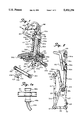
- FIG. 1 is a rear perspective view of a step climber exercise machine constructed in accordance with the present invention
- FIG. 1a is a cross-sectional view taken along lines 1a-1a of FIG. 1;
- FIG. 2 is a side view of the step climber in the storage position
- FIG. 3 is a side view of the step climber in the operating position
- FIG. 4 is a cross-sectional view of the foot supporting segment
- FIG. 5 is a cross-sectional side view of the foot supporting segment
- FIG. 6 is a partial cross-sectional view of the main strut raised in the operating position
- FIG. 7 is a partial cross-sectional view of the main strut shown in the storage position
- FIG. 8 is a partial side cross-sectional view of the upper frame showing the pointed screw engaged in a notch of the ratchet wheel;
- FIG. 9 is a partial side cross-sectional view of the upper frame showing the pointed screw disengaged from the ratchet wheel
- FIG. 10 is a cross-sectional view of the upper frame of the step climber
- FIG. 11 is a partial cross-sectional view of the support bar telescopically mounted in the base member
- FIG. 12 is a partial side cross-sectional view of the support bar telescopically mounted in the base member.
- FIG. 13 is a partial view of the resistance means showing the adjustment valve and upper boot.
- FIG. 1 a collapsible step climber exercise machine constructed in accordance with the principles of the present invention and designated generally as 10.
- the step climber exercise machine includes a base frame having a base member 12, a transverse rear segment 14 and a transverse front segment 16.
- the rear segment 14 and the front segment 16 each include a pair of spaced apart caps, 18a, 18b and 20a, 20b respectively, that are adapted to frictionally engage the ground when the step climber is in use.
- Channel member 22 is attached to the base member 12, preferably by welding the same thereto.
- Pivot plate 27 extends from the top of channel member 22.
- Main strut 24 is partially inserted through pivot plate 27 and into channel member 22 when the exercise machine is in its operating condition (see FIG. 6).
- the main strut 24 is comprised of an outer segment 21 and an inner segment 23.
- the inner segment 23 is friction fitted in the outer segment 21.
- the inner segment 23 extends from the outer segment 21 and is pivotally connected to pivot plate 27 at pivot point 25 as illustrated in FIGS. 3 and 6.
- Screw knob 26 secures the inner segment 23 of main strut 24 to the channel member 22 when the exercise machine is in its operating condition.
- the main strut can be one molded piece comprising a large diameter segment and a reduced diameter segment extending therefrom.
- Front support 28 is secured to transverse front segment 16.
- Beam 30 is attached atop the front support 28.
- Positioned between the channel member 22 and beam 30 is horizontal housing 32 as shown in FIG. 3.
- the end of the horizontal housing 32 furthest from beam 30 extends into pivot plate 27.
- the horizontal housing 32 has an open bottom for receiving the inner segment 23 of main strut 24 when screw knob 26 is manually removed and the step climber 10 is collapsed from its operating position to its storage position in the manner described below.
- Right and left laterally spaced stepping members 34a, 34b are pivotally mounted to front segment 16.
- the right and left stepping members 34a, 34b are substantially identical to each other. Accordingly, only one of the stepping members will be described in detail, it being understood that the description applies equally to the other stepping members.
- the foot supporting segment 36a is partially inserted over stepping member 34a. Screw 35a secures foot supporting segment 36a to stepping member 34a as shown in FIG. 4.
- the foot supporting segment 36a has a plurality of apertures 38a formed therein.
- a compression mat 40a is secured atop foot supporting segment 36a by means of barbed extensions 42a friction fitted in the apertures 38a.
- Compression mat 40a has a plurality of longitudinal and latitudinal projections 44a and 45a, respectively, extending downwardly from the undersurface of the mat as shown in FIG. 5.
- the projections are preferably made of an elastic material such as rubber.
- the top side of compression mat 40a includes a plurality of elongated ribs 46a for providing a non-slip gripping surface.
- Resistance means 50a has a top 52a and a bottom 54a. Bottom 54a is connected to stepping member 34a through the use of a double pivot joint 56a as shown in FIG. 3. Top 52a is attached to the upper frame 48.
- the resistance means 50a comprises a resistance cylinder and a piston rod.
- the resistance means 50a can be of the pneumatic or hydraulic type.
- Lower telescoping boot 58a surrounds the double pivot joint 56a as illustrated in FIGS. 1-3.
- upper telescoping boot 59a surrounds top 52a of resistance means 50a so that the piston rod (not shown) is not exposed.
- Adjustment valve 60a is secured to the resistance means 50a at the bottom of boot 59a for allowing the user to manually select a desired level of tension (see FIG. 13).
- axle 62 is inserted through the hub of ratchet wheel 64.
- the ratchet wheel 64 is secured around the center of axle 62.
- the axle 62 is rotatably mounted in and extends through the right and left sides of the upper frame 48.
- a threaded support plate 68 is secured to the back of upper frame 48, preferably by welding the same thereto.
- a pointed screw 70 having a pointed tip 72 is threaded through support plate 68 to engage a desired notch 74 in ratchet wheel 64 for securing handlebar 80 in place.
- a knob 82 is secured to the end of pointed screw 70 opposite pointed tip 72 so that the user can readily disengage the screw 70 from notch 74 by turning the knob in the manner described below.
- a bushing 84a is secured to the right side of the upper frame 48 and a bushing 84b is secured to the left side of upper frame 48.
- Right support tube 90a is inserted around axle 62, through bushing 84a, and into upper frame 48.
- Right support tube 90a is secured to the axle 62 by a top screw 92a and a bottom screw 94a.
- Left support tube 90b is secured to the axle 62 in upper frame 48 in a similar manner.
- Right support tube 90a extends from the right side of upper frame 48.
- left support tube 90b extends from the left side of upper frame 48.
- right support tube 90a is L-shaped and has an upwardly curved end portion 91a as shown in FIGS. 2 and 3.
- Left support tube 90b is similarly shaped and has an upwardly curved end portion 91b.
- Handlebar 80 is positioned atop the right and left tube ends 91a, 91b. Brackets 96a, 96b secure the tube ends to handlebar 80 (see FIG. 1a).
- the handlebar is shaped to provide both comfort and support to the user of the step climber exercise machine.
- an adjustable display means 98 is mounted atop the upper frame 48.
- the display means 98 is equipped with a computer to provide the user with a variety of information such as the user's heart rate, how many calories are being burned and how much time is remaining to complete the workout.
- the step climber exerciser of the present invention is designed to allow the user to perform exercises with his or her posterior extending passed the foot supporting segments 36a, 36b of stepping members 34a, 34b.
- This is accomplished by having a support bar 100 telescopically mounted through the transverse rear segment 14 and in the base member 12.
- the support bar 100 includes square tube 102 having a stop cap 104 located on one end and a balancing support 106 located at the other end.
- the balancing support 106 preferably has a vertical portion 107 and a horizontal portion 108. The horizontal portion enhances the stability of the step climber.
- a knob 109 is secured to the vertical portion 107 of the balancing support 106 for aiding in the removal of the support bar 100 from the transverse rear segment 14.
- Stop guides 110a, 110b are secured to base member 12 on both sides of square tube 102 for engaging stop cap 104. More specifically, when balancing support 106 is manually pulled away from transverse rear segment 14 a sufficient distance, stop cap 104 contacts stop guides 110a, 110b thereby preventing further removal of support bar 100 from transverse rear segment 14. When the step climber 10 is in the operating condition, support bar 100 is extended. Therefore, if the user of the step climber decides to concentrate the muscles on the back of the leg as well the glutimus maximus muscles while working out, the person is free to stick his or her posterior out passed the foot supporting segments 36a, 36b without causing the step climber to tip over. This is because the support bar 100 provides the necessary balance to prevent such an occurrence.
- support bar 100 has been specifically described for use in conjunction with a step climber, it should be understood that the same is not limited thereto.
- a similar support bar can be used with other exercise machines such as a bicycle or the like which may also have a tendency to tip during use.
- the user Before using the stair climber, the user first pulls support bar 100 from base member 12 until stop cap 104 contacts stop guides 110a, 110b and can extend no further. The user then sets adjustment valves 60a, 60b to a desired level of resistance. To increase the resistance of foot supporting segments 36a, 36b the valves are moved toward closing.
- the person adjusts the handlebar 80 to a level suited to his or her particular measurements. This is accomplished by disengaging tip 72 of pointed screw 70 from notch 74 of ratchet wheel 64 by turning knob 82. The handlebar 80 is then free to rotate. Once a desired position is obtained, the knob 82 is turned in the opposite direction so that the tip 72 of pointed screw 70 engages notch 74 in ratchet wheel 64.
- a person wishing to exercise steps onto foot supporting segments 36a, 36b The user then grasps handlebar 80, which is secured to upper frame 48. He or she may begin exercising by placing downward force on the foot supporting segments 36a, 36b. The downward force on the foot supporting segments is met with directly related opposing forces from resistance means 50a, 50b respectively.
- the step climber exercise machine can be folded up and stored away. This is accomplished by manually inserting support bar 100 through transverse rear segment 14 and into base member 12.
- the display means 98 is folded downward.
- Handlebar 80 is folded toward stepping members 34a, 34b by disengaging pointed screw 70 from notch 74 in ratchet wheel 64 so that the handlebar is free to rotate. Pointed screw 70 is then threaded back into another notch 74 in ratchet wheel 64 to secure the handlebar in place.
- Screw knob 26 is unscrewed from the inner segment 23 of main strut 24 and channel member 22.
- the inner segment 23 is rotated about pivot point 25 and inserted into horizontal housing 32 (see FIGS. 6 and 7).
- the screw knob 26 is then threaded through the horizontal housing 32 and the inner segment 23 of main strut 24 so that the main strut is secured to the horizontal housing.
- the step climber is then in its storage position where it can be conveniently stored away until it is once again ready for use.
Abstract
A foldable step climber exercise machine comprises a base frame having a balancing support telescopically mounted therein, a pair of stepping members pivotally secured to the base frame, a main strut attached to the base frame extending upwardly therefrom and handlebar secured atop the main strut. A different resistance structure is secured to each stepping member for providing resistance when a downward force is placed on the stepping members by the user. Pivots are provided between the main strut and the base frame to allow the step climber to be collapsed from an operating position to a storage position.
Description
The present invention is directed toward a foldable or collapsible step climber exercise machine for providing a cardiovascular workout and, more particularly, to such an exercise machine having a base frame, a pair of stepping members and handlebar wherein the step climber is collapsible for easy storage.
During the last few years step climber exercise machines have become an increasingly preferred method for obtaining a cardiovascular workout. Such machines are also used to tone and shape a person's body. One reason for this trend is the fact that step climber exercisers, commonly referred to as steppers, cause significantly less stress to the knee area than jogging and/or running. Additionally, steppers allow the user to exercise without ever leaving his or her own home.
Step climber exercisers are well known in the art. Such exercise machines are shown, for example, in prior U.S. Pat. Nos. 5,232,420 and 5,230,674. These exercisers are deficient in that they do not have handlebar or other means to allow the user to balance himself during a workout.
Furthermore, the above mentioned devices as well as other known step climbers are not designed to accommodate exercises where the user's posterior extends passed the foot supporting members. See, for example, U.S. Pat. Nos. 4,496,147 and 4,563,001. This prevents the user from tailoring a workout to concentrate certain areas of his or her body. For example, if the user wanted to concentrate on exercising the hamstring area on the back of the leg as well as the glutimus maximus area, the user would preferably have his or her posterior extend passed the foot supporting members while working out. However, the above mentioned devices do not provide the balance required to accommodate such a position and would tip over if such exercises were attempted.
As stated above, step climber exercisers are often used in the privacy of one's home. Some known home fitness devices are foldable so that they can be stored away when not in use. A common drawback to many of these devices is that they are not readily collapsible and require significant effort to be placed in the storage position.
Accordingly, there is a need for a step climber exerciser that allows the user to perform a variety of different exercises without tipping over and is readily collapsible so that it can be stored.
The present invention is designed to overcome the deficiencies of the prior art discussed above. It is an object of this invention to provide a device for simulating step climbing.
It is a further object of this invention to provide a step climber exercise machine that provides the balance needed to allow the user to perform exercises where his or her posterior extends passed the foot supporting members.
It is yet another object of the invention to provide such a device that can be conveniently stored when not in use.
In accordance with the illustrative embodiments, demonstrating features and advantages of the present invention, there is provided a step climber exercise machine which comprises a base frame having a support bar telescopically mounted therein, a pair of stepping members pivotally secured to the base frame, a main strut attached to the base frame extending upwardly therefrom and handlebar secured atop the main strut. Resistance means are secured to the stepping members for providing resistance when a downward force is placed on the stepping members by the user.
The user may simulate step climbing by repeatedly stepping up and down on the stepping members. The resistance means can be adjusted to provide a desired level of resistance.
For the purpose of illustrating the invention, there is shown in the accompanying drawings one form which is presently preferred; it being understood that the invention is not intended to be limited to the precise arrangements and instrumentalities shown.
FIG. 1 is a rear perspective view of a step climber exercise machine constructed in accordance with the present invention;
FIG. 1a is a cross-sectional view taken along lines 1a-1a of FIG. 1;
FIG. 2 is a side view of the step climber in the storage position;
FIG. 3 is a side view of the step climber in the operating position;
FIG. 4 is a cross-sectional view of the foot supporting segment;
FIG. 5 is a cross-sectional side view of the foot supporting segment;
FIG. 6 is a partial cross-sectional view of the main strut raised in the operating position;
FIG. 7 is a partial cross-sectional view of the main strut shown in the storage position;
FIG. 8 is a partial side cross-sectional view of the upper frame showing the pointed screw engaged in a notch of the ratchet wheel;
FIG. 9 is a partial side cross-sectional view of the upper frame showing the pointed screw disengaged from the ratchet wheel;
FIG. 10 is a cross-sectional view of the upper frame of the step climber;
FIG. 11 is a partial cross-sectional view of the support bar telescopically mounted in the base member;
FIG. 12 is a partial side cross-sectional view of the support bar telescopically mounted in the base member, and
FIG. 13 is a partial view of the resistance means showing the adjustment valve and upper boot.
Referring now to the drawings in detail wherein like reference numerals have been used throughout the various figures to designate like elements, there is shown in FIG. 1 a collapsible step climber exercise machine constructed in accordance with the principles of the present invention and designated generally as 10.
The step climber exercise machine includes a base frame having a base member 12, a transverse rear segment 14 and a transverse front segment 16. In the preferred embodiment, the rear segment 14 and the front segment 16 each include a pair of spaced apart caps, 18a, 18b and 20a, 20b respectively, that are adapted to frictionally engage the ground when the step climber is in use.
In the preferred embodiment, the main strut 24 is comprised of an outer segment 21 and an inner segment 23. The inner segment 23 is friction fitted in the outer segment 21. The inner segment 23 extends from the outer segment 21 and is pivotally connected to pivot plate 27 at pivot point 25 as illustrated in FIGS. 3 and 6. Screw knob 26 secures the inner segment 23 of main strut 24 to the channel member 22 when the exercise machine is in its operating condition. In an alternate embodiment, the main strut can be one molded piece comprising a large diameter segment and a reduced diameter segment extending therefrom.
Right and left laterally spaced stepping members 34a, 34b are pivotally mounted to front segment 16. The right and left stepping members 34a, 34b are substantially identical to each other. Accordingly, only one of the stepping members will be described in detail, it being understood that the description applies equally to the other stepping members. The foot supporting segment 36a is partially inserted over stepping member 34a. Screw 35a secures foot supporting segment 36a to stepping member 34a as shown in FIG. 4. The foot supporting segment 36a has a plurality of apertures 38a formed therein.
A compression mat 40a is secured atop foot supporting segment 36a by means of barbed extensions 42a friction fitted in the apertures 38a. Compression mat 40a has a plurality of longitudinal and latitudinal projections 44a and 45a, respectively, extending downwardly from the undersurface of the mat as shown in FIG. 5. The projections are preferably made of an elastic material such as rubber. When the user steps down on segment 36a the projections 44a, 45a of compression mat 40a are slightly compressed so that the user encounters a cushioned surface. The top side of compression mat 40a includes a plurality of elongated ribs 46a for providing a non-slip gripping surface.
Referring back to FIG. 1, upper frame 48 is secured atop main strut 24. Right and left resistance means 50a and 50b are connected to a corresponding stepping member 34a and 34b and to the upper frame 48. Again, while only one resistance means will be described in detail, it should be understood that the description equally applies to the other resistance means. Resistance means 50a has a top 52a and a bottom 54a. Bottom 54a is connected to stepping member 34a through the use of a double pivot joint 56a as shown in FIG. 3. Top 52a is attached to the upper frame 48. In a preferred embodiment, the resistance means 50a comprises a resistance cylinder and a piston rod. The resistance means 50a can be of the pneumatic or hydraulic type. Lower telescoping boot 58a surrounds the double pivot joint 56a as illustrated in FIGS. 1-3.
Similarly, upper telescoping boot 59a surrounds top 52a of resistance means 50a so that the piston rod (not shown) is not exposed. Adjustment valve 60a is secured to the resistance means 50a at the bottom of boot 59a for allowing the user to manually select a desired level of tension (see FIG. 13).
Referring to FIGS. 8-10, axle 62 is inserted through the hub of ratchet wheel 64. The ratchet wheel 64 is secured around the center of axle 62. The axle 62 is rotatably mounted in and extends through the right and left sides of the upper frame 48. A threaded support plate 68 is secured to the back of upper frame 48, preferably by welding the same thereto. A pointed screw 70 having a pointed tip 72 is threaded through support plate 68 to engage a desired notch 74 in ratchet wheel 64 for securing handlebar 80 in place. A knob 82 is secured to the end of pointed screw 70 opposite pointed tip 72 so that the user can readily disengage the screw 70 from notch 74 by turning the knob in the manner described below.
A bushing 84a is secured to the right side of the upper frame 48 and a bushing 84b is secured to the left side of upper frame 48. Right support tube 90a is inserted around axle 62, through bushing 84a, and into upper frame 48. Right support tube 90a is secured to the axle 62 by a top screw 92a and a bottom screw 94a. Left support tube 90b is secured to the axle 62 in upper frame 48 in a similar manner.
In the preferred embodiment, an adjustable display means 98 is mounted atop the upper frame 48. The display means 98 is equipped with a computer to provide the user with a variety of information such as the user's heart rate, how many calories are being burned and how much time is remaining to complete the workout.
Referring to FIGS. 11 and 12, the step climber exerciser of the present invention is designed to allow the user to perform exercises with his or her posterior extending passed the foot supporting segments 36a, 36b of stepping members 34a, 34b. This is accomplished by having a support bar 100 telescopically mounted through the transverse rear segment 14 and in the base member 12. The support bar 100 includes square tube 102 having a stop cap 104 located on one end and a balancing support 106 located at the other end. The balancing support 106 preferably has a vertical portion 107 and a horizontal portion 108. The horizontal portion enhances the stability of the step climber. A knob 109 is secured to the vertical portion 107 of the balancing support 106 for aiding in the removal of the support bar 100 from the transverse rear segment 14.
Stop guides 110a, 110b are secured to base member 12 on both sides of square tube 102 for engaging stop cap 104. More specifically, when balancing support 106 is manually pulled away from transverse rear segment 14 a sufficient distance, stop cap 104 contacts stop guides 110a, 110b thereby preventing further removal of support bar 100 from transverse rear segment 14. When the step climber 10 is in the operating condition, support bar 100 is extended. Therefore, if the user of the step climber decides to concentrate the muscles on the back of the leg as well the glutimus maximus muscles while working out, the person is free to stick his or her posterior out passed the foot supporting segments 36a, 36b without causing the step climber to tip over. This is because the support bar 100 provides the necessary balance to prevent such an occurrence.
While the support bar 100 has been specifically described for use in conjunction with a step climber, it should be understood that the same is not limited thereto. A similar support bar can be used with other exercise machines such as a bicycle or the like which may also have a tendency to tip during use.
To facilitate an understanding of the principles associated with the foregoing apparatus, its operation will now be briefly described. Before using the stair climber, the user first pulls support bar 100 from base member 12 until stop cap 104 contacts stop guides 110a, 110b and can extend no further. The user then sets adjustment valves 60a, 60b to a desired level of resistance. To increase the resistance of foot supporting segments 36a, 36b the valves are moved toward closing.
Next, the person adjusts the handlebar 80 to a level suited to his or her particular measurements. This is accomplished by disengaging tip 72 of pointed screw 70 from notch 74 of ratchet wheel 64 by turning knob 82. The handlebar 80 is then free to rotate. Once a desired position is obtained, the knob 82 is turned in the opposite direction so that the tip 72 of pointed screw 70 engages notch 74 in ratchet wheel 64.
A person wishing to exercise steps onto foot supporting segments 36a, 36b. The user then grasps handlebar 80, which is secured to upper frame 48. He or she may begin exercising by placing downward force on the foot supporting segments 36a, 36b. The downward force on the foot supporting segments is met with directly related opposing forces from resistance means 50a, 50b respectively.
After an exercise session is completed, the step climber exercise machine can be folded up and stored away. This is accomplished by manually inserting support bar 100 through transverse rear segment 14 and into base member 12. The display means 98 is folded downward. Handlebar 80 is folded toward stepping members 34a, 34b by disengaging pointed screw 70 from notch 74 in ratchet wheel 64 so that the handlebar is free to rotate. Pointed screw 70 is then threaded back into another notch 74 in ratchet wheel 64 to secure the handlebar in place.
The present invention may be embodied in other specific forms without departing from the spirit or essential attributes thereof and accordingly reference should be made to the appended claims rather than to the foregoing specification as indicating the scope of the invention.
Claims (8)
1. A collapsible step climber exercise machine having an operating position and a storage position, said exercise machine comprising:
a base frame having a longitudinally extending base member, a transverse rear segment and a transverse front segment;
a pair of laterally spaced stepping members pivotally mounted on said base frame;
resistance means having tops and bottoms, said bottom of each of said resistance means being pivotally attached to a different one of said stepping members for providing resistance when a downward force is placed on one of said stepping members;
a support means mounted on said base member between said front and rear segments, said support means being foldable for collapsing said exercise machine from said operating position to said storage position;
an upper frame secured to the end of said support means distal to said base frame;
a handlebar for providing support for a person;
means for adjustably securing said handlebar to said upper frame; and
attachment means for attaching said resistance means to said upper frame.
2. The exercise machine of claim 1 wherein said support means comprises:
a channel member mounted on said base member between said front and rear segments, said channel member extending upwardly from said base member; and
a main strut being pivotally mounted to said channel member when said exercise machine is in said operating position, said main strut being foldable towards said rear segment when said exercise machine is placed in said storage condition.
3. The exercise machine of claim 1 wherein said means for adjustably securing said handlebar to said upper frame includes:
a ratchet wheel having a hub, said ratchet wheel further having a plurality of notches;
an axle mounted through said hub of said ratchet wheel, said axle rotatably mounted in and extending through said upper frame;
a right support tube and a left support tube, said right support tube being partially inserted around said axle and extending from the right side of said upper frame, said left support tube being partially inserted around said axle and extending from the left side of said upper frame, said handlebar being attached atop said right and left support tubes; and
a pointed screw having a pointed tip threaded through said upper frame, said pointed tip being engageable with one of said notches of said ratchet wheel for securing said handlebar in a predetermined position.
4. The exercise machine of claim 3 further comprising a knob attached to the end of said pointed screw opposite said pointed tip for facilitating the threading of said pointed screw through said upper frame.
5. The exercise machine of claim 1 further comprising:
a support bar telescopically mounted in said base frame, said support bar partially extending from said base frame for avoiding tipping of the exercise machine when in said operating position.
6. The exercise machine of claim 5 further comprising stopping means for preventing removal of said support bar from said base frame.
7. The exercise machine of claim 1 further including an adjustable display means mounted atop said upper frame.
8. The exercise machine of claim 1 further comprising:
each of said foot supporting segments having a plurality of apertures formed therein;
a right compression mat and a left compression mat, said compression mats each having a top side and an underside;
a plurality of longitudinal and latitudinal projections downwardly extending from said underside of each of said mats, and
a plurality of barbed extensions downwardly extending from said underside of each of said mats, said downwardly extending barbed extensions on said right compression mat being friction fitted in said apertures in said right foot supporting segment, said downwardly extending barbed extensions on said left compression mat being friction fitted in said apertures in said left foot supporting segment.
Priority Applications (1)
| Application Number | Priority Date | Filing Date | Title |
|---|---|---|---|
| US08/254,912 US5403254A (en) | 1994-06-06 | 1994-06-06 | Foldable step climber exercise machine |
Applications Claiming Priority (1)
| Application Number | Priority Date | Filing Date | Title |
|---|---|---|---|
| US08/254,912 US5403254A (en) | 1994-06-06 | 1994-06-06 | Foldable step climber exercise machine |
Publications (1)
| Publication Number | Publication Date |
|---|---|
| US5403254A true US5403254A (en) | 1995-04-04 |
Family
ID=22966068
Family Applications (1)
| Application Number | Title | Priority Date | Filing Date |
|---|---|---|---|
| US08/254,912 Expired - Fee Related US5403254A (en) | 1994-06-06 | 1994-06-06 | Foldable step climber exercise machine |
Country Status (1)
| Country | Link |
|---|---|
| US (1) | US5403254A (en) |
Cited By (32)
| Publication number | Priority date | Publication date | Assignee | Title |
|---|---|---|---|---|
| USD381717S (en) * | 1995-07-24 | 1997-07-29 | Stairmaster Sports/Medical Products, L.P. | Handle for an exercise apparatus |
| US5762587A (en) * | 1995-02-01 | 1998-06-09 | Icon Health & Fitness, Inc. | Exercise machine with adjustable-resistance, hydraulic cylinder |
| US20020151413A1 (en) * | 1997-10-28 | 2002-10-17 | Dalebout William T. | Fold-out treadmill |
| US20030216223A1 (en) * | 2002-05-14 | 2003-11-20 | Chuang Jin Chen | Stepping exerciser having increased lateral movement |
| US20050148443A1 (en) * | 1996-01-30 | 2005-07-07 | Watterson Scott R. | Reorienting treadmill |
| USRE39904E1 (en) | 2001-04-17 | 2007-10-30 | Stamina Products, Inc. | Combined elliptical cycling and stepping exerciser |
| US20080287816A1 (en) * | 2007-05-17 | 2008-11-20 | Edward Honda | Adjustable sensors for use with exercise apparatus |
| US7892154B1 (en) * | 2006-06-07 | 2011-02-22 | Austen Alexa | Shock absorber ankle exercise device |
| US20120108397A1 (en) * | 2010-11-02 | 2012-05-03 | Jao-Hsing Tsai | Leg Stretching Device |
| US10188890B2 (en) | 2013-12-26 | 2019-01-29 | Icon Health & Fitness, Inc. | Magnetic resistance mechanism in a cable machine |
| US10252109B2 (en) | 2016-05-13 | 2019-04-09 | Icon Health & Fitness, Inc. | Weight platform treadmill |
| US10258828B2 (en) | 2015-01-16 | 2019-04-16 | Icon Health & Fitness, Inc. | Controls for an exercise device |
| US10272317B2 (en) | 2016-03-18 | 2019-04-30 | Icon Health & Fitness, Inc. | Lighted pace feature in a treadmill |
| US10279212B2 (en) | 2013-03-14 | 2019-05-07 | Icon Health & Fitness, Inc. | Strength training apparatus with flywheel and related methods |
| US10293211B2 (en) | 2016-03-18 | 2019-05-21 | Icon Health & Fitness, Inc. | Coordinated weight selection |
| US10343017B2 (en) | 2016-11-01 | 2019-07-09 | Icon Health & Fitness, Inc. | Distance sensor for console positioning |
| US10376736B2 (en) | 2016-10-12 | 2019-08-13 | Icon Health & Fitness, Inc. | Cooling an exercise device during a dive motor runway condition |
| US10426989B2 (en) | 2014-06-09 | 2019-10-01 | Icon Health & Fitness, Inc. | Cable system incorporated into a treadmill |
| US10433612B2 (en) | 2014-03-10 | 2019-10-08 | Icon Health & Fitness, Inc. | Pressure sensor to quantify work |
| US10441844B2 (en) | 2016-07-01 | 2019-10-15 | Icon Health & Fitness, Inc. | Cooling systems and methods for exercise equipment |
| US10471299B2 (en) | 2016-07-01 | 2019-11-12 | Icon Health & Fitness, Inc. | Systems and methods for cooling internal exercise equipment components |
| US10493349B2 (en) | 2016-03-18 | 2019-12-03 | Icon Health & Fitness, Inc. | Display on exercise device |
| US10500473B2 (en) | 2016-10-10 | 2019-12-10 | Icon Health & Fitness, Inc. | Console positioning |
| US10543395B2 (en) | 2016-12-05 | 2020-01-28 | Icon Health & Fitness, Inc. | Offsetting treadmill deck weight during operation |
| US10561894B2 (en) | 2016-03-18 | 2020-02-18 | Icon Health & Fitness, Inc. | Treadmill with removable supports |
| US10569121B2 (en) | 2016-12-05 | 2020-02-25 | Icon Health & Fitness, Inc. | Pull cable resistance mechanism in a treadmill |
| US10625137B2 (en) | 2016-03-18 | 2020-04-21 | Icon Health & Fitness, Inc. | Coordinated displays in an exercise device |
| US10625114B2 (en) | 2016-11-01 | 2020-04-21 | Icon Health & Fitness, Inc. | Elliptical and stationary bicycle apparatus including row functionality |
| US10661114B2 (en) | 2016-11-01 | 2020-05-26 | Icon Health & Fitness, Inc. | Body weight lift mechanism on treadmill |
| US10729965B2 (en) | 2017-12-22 | 2020-08-04 | Icon Health & Fitness, Inc. | Audible belt guide in a treadmill |
| US10953305B2 (en) | 2015-08-26 | 2021-03-23 | Icon Health & Fitness, Inc. | Strength exercise mechanisms |
| US11451108B2 (en) | 2017-08-16 | 2022-09-20 | Ifit Inc. | Systems and methods for axial impact resistance in electric motors |
Citations (6)
| Publication number | Priority date | Publication date | Assignee | Title |
|---|---|---|---|---|
| US4620701A (en) * | 1984-08-20 | 1986-11-04 | Mojden Daniel R | Adjustable exercise apparatus |
| US4838543A (en) * | 1988-10-28 | 1989-06-13 | Precor Incorporated | Low impact exercise equipment |
| US5145476A (en) * | 1991-12-13 | 1992-09-08 | Roadmaster Corporation | Folding stepper |
| US5169360A (en) * | 1990-10-16 | 1992-12-08 | Sports Step, Inc. | Aerobic step device |
| US5222927A (en) * | 1992-01-31 | 1993-06-29 | Chang Lee C | Collapsible stepper climber exerciser |
| US5226866A (en) * | 1992-05-01 | 1993-07-13 | Nordictrack, Inc. | Trimodal exercise apparatus |
-
1994
- 1994-06-06 US US08/254,912 patent/US5403254A/en not_active Expired - Fee Related
Patent Citations (6)
| Publication number | Priority date | Publication date | Assignee | Title |
|---|---|---|---|---|
| US4620701A (en) * | 1984-08-20 | 1986-11-04 | Mojden Daniel R | Adjustable exercise apparatus |
| US4838543A (en) * | 1988-10-28 | 1989-06-13 | Precor Incorporated | Low impact exercise equipment |
| US5169360A (en) * | 1990-10-16 | 1992-12-08 | Sports Step, Inc. | Aerobic step device |
| US5145476A (en) * | 1991-12-13 | 1992-09-08 | Roadmaster Corporation | Folding stepper |
| US5222927A (en) * | 1992-01-31 | 1993-06-29 | Chang Lee C | Collapsible stepper climber exerciser |
| US5226866A (en) * | 1992-05-01 | 1993-07-13 | Nordictrack, Inc. | Trimodal exercise apparatus |
Cited By (35)
| Publication number | Priority date | Publication date | Assignee | Title |
|---|---|---|---|---|
| US5762587A (en) * | 1995-02-01 | 1998-06-09 | Icon Health & Fitness, Inc. | Exercise machine with adjustable-resistance, hydraulic cylinder |
| USD381717S (en) * | 1995-07-24 | 1997-07-29 | Stairmaster Sports/Medical Products, L.P. | Handle for an exercise apparatus |
| US20050148443A1 (en) * | 1996-01-30 | 2005-07-07 | Watterson Scott R. | Reorienting treadmill |
| US20050148442A1 (en) * | 1996-01-30 | 2005-07-07 | Watterson Scott R. | Reorienting treadmill |
| US20020151413A1 (en) * | 1997-10-28 | 2002-10-17 | Dalebout William T. | Fold-out treadmill |
| USRE39904E1 (en) | 2001-04-17 | 2007-10-30 | Stamina Products, Inc. | Combined elliptical cycling and stepping exerciser |
| US20030216223A1 (en) * | 2002-05-14 | 2003-11-20 | Chuang Jin Chen | Stepping exerciser having increased lateral movement |
| US6830539B2 (en) * | 2002-05-14 | 2004-12-14 | Jin Chen Chuang | Stepping exerciser having increased lateral movement |
| US7892154B1 (en) * | 2006-06-07 | 2011-02-22 | Austen Alexa | Shock absorber ankle exercise device |
| US20080287816A1 (en) * | 2007-05-17 | 2008-11-20 | Edward Honda | Adjustable sensors for use with exercise apparatus |
| US8082029B2 (en) * | 2007-05-17 | 2011-12-20 | Brunswick Corporation | Adjustable sensors for use with exercise apparatus |
| US20120108397A1 (en) * | 2010-11-02 | 2012-05-03 | Jao-Hsing Tsai | Leg Stretching Device |
| US10279212B2 (en) | 2013-03-14 | 2019-05-07 | Icon Health & Fitness, Inc. | Strength training apparatus with flywheel and related methods |
| US10188890B2 (en) | 2013-12-26 | 2019-01-29 | Icon Health & Fitness, Inc. | Magnetic resistance mechanism in a cable machine |
| US10433612B2 (en) | 2014-03-10 | 2019-10-08 | Icon Health & Fitness, Inc. | Pressure sensor to quantify work |
| US10426989B2 (en) | 2014-06-09 | 2019-10-01 | Icon Health & Fitness, Inc. | Cable system incorporated into a treadmill |
| US10258828B2 (en) | 2015-01-16 | 2019-04-16 | Icon Health & Fitness, Inc. | Controls for an exercise device |
| US10953305B2 (en) | 2015-08-26 | 2021-03-23 | Icon Health & Fitness, Inc. | Strength exercise mechanisms |
| US10493349B2 (en) | 2016-03-18 | 2019-12-03 | Icon Health & Fitness, Inc. | Display on exercise device |
| US10272317B2 (en) | 2016-03-18 | 2019-04-30 | Icon Health & Fitness, Inc. | Lighted pace feature in a treadmill |
| US10293211B2 (en) | 2016-03-18 | 2019-05-21 | Icon Health & Fitness, Inc. | Coordinated weight selection |
| US10561894B2 (en) | 2016-03-18 | 2020-02-18 | Icon Health & Fitness, Inc. | Treadmill with removable supports |
| US10625137B2 (en) | 2016-03-18 | 2020-04-21 | Icon Health & Fitness, Inc. | Coordinated displays in an exercise device |
| US10252109B2 (en) | 2016-05-13 | 2019-04-09 | Icon Health & Fitness, Inc. | Weight platform treadmill |
| US10441844B2 (en) | 2016-07-01 | 2019-10-15 | Icon Health & Fitness, Inc. | Cooling systems and methods for exercise equipment |
| US10471299B2 (en) | 2016-07-01 | 2019-11-12 | Icon Health & Fitness, Inc. | Systems and methods for cooling internal exercise equipment components |
| US10500473B2 (en) | 2016-10-10 | 2019-12-10 | Icon Health & Fitness, Inc. | Console positioning |
| US10376736B2 (en) | 2016-10-12 | 2019-08-13 | Icon Health & Fitness, Inc. | Cooling an exercise device during a dive motor runway condition |
| US10343017B2 (en) | 2016-11-01 | 2019-07-09 | Icon Health & Fitness, Inc. | Distance sensor for console positioning |
| US10625114B2 (en) | 2016-11-01 | 2020-04-21 | Icon Health & Fitness, Inc. | Elliptical and stationary bicycle apparatus including row functionality |
| US10661114B2 (en) | 2016-11-01 | 2020-05-26 | Icon Health & Fitness, Inc. | Body weight lift mechanism on treadmill |
| US10569121B2 (en) | 2016-12-05 | 2020-02-25 | Icon Health & Fitness, Inc. | Pull cable resistance mechanism in a treadmill |
| US10543395B2 (en) | 2016-12-05 | 2020-01-28 | Icon Health & Fitness, Inc. | Offsetting treadmill deck weight during operation |
| US11451108B2 (en) | 2017-08-16 | 2022-09-20 | Ifit Inc. | Systems and methods for axial impact resistance in electric motors |
| US10729965B2 (en) | 2017-12-22 | 2020-08-04 | Icon Health & Fitness, Inc. | Audible belt guide in a treadmill |
Similar Documents
| Publication | Publication Date | Title |
|---|---|---|
| US5403254A (en) | Foldable step climber exercise machine | |
| US5480365A (en) | Foldable handlebar for exercise machine | |
| US5039091A (en) | Exercise machine having flywheel with variable resistance | |
| US4564193A (en) | Exercising device for lifting weights | |
| US6520891B1 (en) | Treadmill with upper body exercise means | |
| US6676579B1 (en) | Yoga balance trainer | |
| US4445684A (en) | Leg stretching machine | |
| US7621852B2 (en) | Exercise cycle assembly | |
| US8678985B2 (en) | Balance training and exercise device | |
| EP0591729B1 (en) | Exerciser with an arm exercise unit and a leg exercise unit | |
| US6309329B2 (en) | Abdominal exercise device and method | |
| US7708670B2 (en) | Seated row exercise system | |
| US7811216B2 (en) | Inflatable exercise apparatus | |
| US20100137115A1 (en) | Push up trainer | |
| US20070082795A1 (en) | Free weight support device | |
| US5145476A (en) | Folding stepper | |
| WO2005123197A1 (en) | Portable exercice device and method of preventing lactic-acid build-up | |
| EP0716865B1 (en) | Resilient platform exercise device | |
| US5152732A (en) | Portable gym | |
| US5967950A (en) | Load mechanism of body building device | |
| US4111415A (en) | Exercising apparatus to aid in the practice of karate | |
| US20090011906A1 (en) | Rebounding exerciser | |
| US5439433A (en) | Support bar for exercise machine | |
| US5439432A (en) | Foot supporting member for exercise machine | |
| US7198592B1 (en) | Abdominal exerciser |
Legal Events
| Date | Code | Title | Description |
|---|---|---|---|
| AS | Assignment |
Owner name: PHYSIQ, INC., NEW JERSEY Free format text: ASSIGNMENT OF ASSIGNORS INTEREST;ASSIGNORS:LUNDIN, CHRISTOPHER B.;STEVENS, CLIVE G.;REEL/FRAME:007031/0226 Effective date: 19940514 |
|
| FPAY | Fee payment |
Year of fee payment: 4 |
|
| REMI | Maintenance fee reminder mailed | ||
| LAPS | Lapse for failure to pay maintenance fees | ||
| STCH | Information on status: patent discontinuation |
Free format text: PATENT EXPIRED DUE TO NONPAYMENT OF MAINTENANCE FEES UNDER 37 CFR 1.362 |
|
| FP | Lapsed due to failure to pay maintenance fee |
Effective date: 20030404 |