US5396331A - Method for executing three-dimensional measurement utilizing correctively computing the absolute positions of CCD cameras when image data vary - Google Patents
Method for executing three-dimensional measurement utilizing correctively computing the absolute positions of CCD cameras when image data vary Download PDFInfo
- Publication number
- US5396331A US5396331A US08/103,911 US10391193A US5396331A US 5396331 A US5396331 A US 5396331A US 10391193 A US10391193 A US 10391193A US 5396331 A US5396331 A US 5396331A
- Authority
- US
- United States
- Prior art keywords
- ccd cameras
- measurable
- points
- image data
- workpiece
- Prior art date
- Legal status (The legal status is an assumption and is not a legal conclusion. Google has not performed a legal analysis and makes no representation as to the accuracy of the status listed.)
- Expired - Lifetime
Links
- 238000000034 method Methods 0.000 title claims abstract description 22
- 238000005259 measurement Methods 0.000 title description 11
- 230000036544 posture Effects 0.000 description 6
- 238000007796 conventional method Methods 0.000 description 3
- 230000005540 biological transmission Effects 0.000 description 2
- 239000000969 carrier Substances 0.000 description 2
- 230000002159 abnormal effect Effects 0.000 description 1
- 230000000694 effects Effects 0.000 description 1
- 230000001678 irradiating effect Effects 0.000 description 1
- 230000026676 system process Effects 0.000 description 1
Images


Classifications
-
- G—PHYSICS
- G01—MEASURING; TESTING
- G01B—MEASURING LENGTH, THICKNESS OR SIMILAR LINEAR DIMENSIONS; MEASURING ANGLES; MEASURING AREAS; MEASURING IRREGULARITIES OF SURFACES OR CONTOURS
- G01B11/00—Measuring arrangements characterised by the use of optical techniques
- G01B11/02—Measuring arrangements characterised by the use of optical techniques for measuring length, width or thickness
- G01B11/024—Measuring arrangements characterised by the use of optical techniques for measuring length, width or thickness by means of diode-array scanning
Definitions
- the present invention relates to a method of executing a three-dimensional measurement for measuring dimension of a measureable object such as an automotive body or a press mold or the like. More particularly, the invention relates to a method of measuring a three-dimensional dimension of a workpiece mounted on an objective position by providing a plurality of CCD cameras in position close to a measurable object.
- a measuring jig B is secured to a predetermined measuring position in order to stably hold an objective workpiece A.
- the objective workpiece A is positioned on the measuring jig B.
- a pair of theodolites 1 and 2 are set to predetermined positions in front of a measurable surface of the positioned workpiece A.
- Each of these theodolites 1 and 2 incorporates a high-precision telescope which is swingably held in the horizontal and vertical directions. When the measurable target point is caught in the center of the telescopic lens, horizontal and vertical angles of the telescope are externally displayed.
- a plurality of reference-point members C needed for determining positional relationship between a pair of theodolites 1 and 2 and the measurable workpiece A are installed to at least four locations in the periphery of the measurable workpiece A positioned on the measuring jig B.
- a reference bar F is placed on the positioned workpiece A or at any optional position in the periphery of the measurable workpiece A.
- the reference bar F has a known distance L between a pair of points D and E.
- a pair of theodolites 1 and 2 are activated to sequentially measure positions of a plurality of reference-point members C.
- those theodolites 1 and 2 sequentially transmit horizontal and vertical directional data to a computer system (not shown).
- the theodolites 1 and 2 respectively measure positions of a pair of points D and E of the reference bar F before transmitting those position data to the computer system.
- the computer system On receipt of those position data covering 6 points measured by those theodolites 1 and 2, based on these position data, the computer system computes relative positions and postures of those theodolites 1 and 2, and then, based on the position data, the computer system computes relative positions and postures of these theodolites 1 and 2, and then, based on the distance data L between a pair of points D and E of the reference bar F, the computer system computes absolute positions and postures of the theodolites 1 and 2.
- FIG. 4 presents an operational flowchart of those sequential processes described above.
- three-dimensional dimension of an objective workpiece A can be measured in a factory that manufactures the workpiece A.
- the invention provides a novel method of measuring three-dimensional dimension of a measurable object by computing positions of a predetermined number of measuring points on the measurable object based on image data picked up by a plurality of CCD cameras.
- a plurality of reference-point members are installed to at least four locations in the periphery of or on the measurable object, and in addition, a reference bar having a known distance between a pair of points is also provided.
- a computer system computes positions of measurable points based on image data transmitted from those plural CCD cameras, initially, among those image data, based on horizontal and vertical angles of those reference-point members and a pair of points of the reference bar against light axes of a plurality of CCD cameras and also based on the distance between a pair of points of the reference bar, the computer system computes absolute positions of these CCD cameras, and then based on these data as reference, the computer system computes positions of measurable points, and in addition, whenever these image data vary, the computer system again computes absolute positions of those CCD cameras.
- the novel method according to the invention securely achieves high-precision measurement of three-dimensional dimensions of a measurable object by initially computing absolute positions of a plurality of CCD cameras based on those data related to a plurality of reference-point members and a reference bar contained in image data transmitted from those plural CCD cameras before eventually computing measurable points based on image data.
- FIG. 1 is a perspective view showing an example of arrangement of a variety of measuring instruments while executing the method of measuring three-dimensional dimension of a measurable workpiece according to the method embodied by the invention
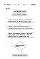
- FIG. 2 is an operational flowcart designating procedure to implement the method of measuring three-dimensional dimension of a measurable workpiece according to an embodiment of the invention
- FIG. 3 is a perspective view showing an example of arrangement of a variety of measuring instruments used for executing a conventional method of measuring three-dimensional dimension of a measurable workpiece;
- FIG. 4 is an operational flowchart designating procedure to implement the conventional method of measuring three-dimensional dimension of a measurable workpiece.
- FIG. 1 is a perspective view showing an example of arrangement of a variety of measuring instruments used for measuring three-dimensional dimension of a measurable workpiece according to the method embodied by the invention.
- the reference character A shown in FIG. 1 designates a measurable workpiece.
- the reference character B designates a measuring jig which stably positions and holds the measurable workpiece A.
- the reference character C designates four reference-point members which are disposed in the periphery of the measurable workpiece A.
- the reference character F designates a reference bar having a known distance between a pair of points D and E.
- a plurality of light emitting diodes are built in the center of each reference-point member C and the center point between a pair of points D and E of the reference bar F. Light points of those light emitting diodes are respectively designated as the measurable points.
- the reference numeral 10 shown in FIG. 1 designates a first CCD camera which is mounted on a tripod 11.
- the reference numeral 12 designates a second CCD camera which is mounted on a tripod 13.
- These first and second CCD cameras 10 and 12 are properly set to predetermined positions in front of a measurable workpiece A in a specific range in order that a measurable object A, those reference-point members C disposed in the periphery of the workpiece A, and the reference bar F, can properly be accommodated in each frame of those first and second CCD cameras 10 and 12.
- the reference numeral 14 designates a computer unit incorporating an image processor which initially computes actual positions of the first and second CCD cameras 10 and 12 based on image data transmitted from these CCD cameras 10 and 12, and then computes three-dimensional dimension of the measurable workpiece A.
- the first and second CCD cameras 10 and 12 After correctly positioning the measurable workpiece A, the first and second CCD cameras 10 and 12, those reference-point members C, and the reference bar F, in order to measure three-dimensional dimension of the measurable workpiece A, as shown in FIG. 1, initially, image data of the measurable workpiece A including periphery of the workpiece A picked up by the first and second CCD cameras 10 and 12 are transmitted to the computer unit 14.
- the computer unit 14 On receipt of image data, initially, among those image data from the first and second CCD cameras 10 and 12, the computer unit 14 computes horizontal and vertical angles of those four reference-point members C disposed in the periphery of the measurable workpiece A against the light axis of the first CCD camera 10, and simultaneously, it also computes horizontal and vertical angles of those reference-point members C against light axes of a pair of points D and E of the reference bar F.
- the computer unit 14 computes horizontal and vertical angles of those four reference-point members C disposed in the periphery of the measurable workpiece A against light axis of the second CCD camera 12, and simultaneously, it also computes horizontal and vertical angles of those reference-point-members C against light axes of a pair of points D and E of the reference bar F.
- the computer unit 14 computes relative positions and postures (in other words, direction of light axes) of the first and second CCD cameras 10 and 12.
- the computer unit 14 computes absolute positions and postures of the first and second CCD cameras 10 and 12.
- the computer unit 14 After correctly identifying absolute positions of the first and second CCD cameras 10 and 12, based on those data transmitted to the computer unit 14, the computer unit 14 computes horizontal and vertical angles of predetermined measurable points on the measurable workpiece A against light axes of those first and second CCD cameras 10 and 12, and then computes data of those measurable points based on triangulation to determine three-dimensional dimension of the workpiece A before completing the whole measuring processes.
- a plurality of characteristic spots on the measurable workpiece A may be available for composing measurable points on the workpiece A.
- all the measurable surfaces of the workpiece A are sequentially irradiated by laser spot beam.
- the computer unit 14 uses laser spot beam as a measuring point, whenever image data transmitted to the computer unit 14 vary in association with the shift of laser spot beam on the measurable surface, the computer unit 14 repeatedly executes all the computations described above in order to sequentially compute positions of respective points irradiated by laser spot beam. The permits the computer unit 14 to correctly identify overall dimension of the measurable surface to complete measurement of three-dimensional dimension of the measurable workpiece A.
- the computer unit 14 does not compute dimension of the objective workpiece A solely by means of a single-frame image data of the objective workpiece A, but the computer unit 14 computes dimension of the workpiece A from multi-frame image data of the workpiece A. Whenever image data vary, based on the method described above, the computer unit 14 initially computes absolute positions of a pair of CCD camera 10 and 12, and finally, based on the data of absolute positions of these CCD cameras 10 and 12, the computer unit 14 computes positions of measurable points.
- the computer unit 14 securely computes absolute positions of these CCD cameras 10 and 12 before computing actual positions of measurable points, even when the positional relationship may vary between those CCD cameras 10 and 12 and the objective workpiece A subsequent to transmission of unwanted vibration to the floor of the measuring location while spending a certain period of time for execution of measurement as in the case of measuring dimension of the workpiece A by sequentially irradiating surface of the workpiece A with laser spot beam like the above case, the varied positional relationship does not cause error to be generated in the measured result, and therefore, the three-dimensional measuring system embodied by the invention can constantly execute measurement of three dimensional dimension of the objective workpiece A with extreme precision.
- FIG. 2 presents an operational flowchart designating sequential procedure for executing the three-dimensional measuring processes described above.
- the invention provides a novel method of measuring three-dimensional dimension of a measurable object A by installing a plurality of reference-point members to at least four locations in the periphery of or on the objective workpiece A and by providing a reference bar having a known distance between a pair of points thereof.
- the computer unit computes absolute positions of these CCD cameras based on horizontal and vertical angles of those reference-point members and two points of the reference bar against light axes of those CCD cameras and also based on the distance between those two points of the reference bar among image data transmitted from those CCD cameras.
- the computer unit computes positions of measurable points. Furthermore, whenever those image data vary, the computer unit correctively computes absolute positions of respective CCD cameras.
Abstract
Description
Claims (1)
Priority Applications (1)
| Application Number | Priority Date | Filing Date | Title |
|---|---|---|---|
| US08/103,911 US5396331A (en) | 1993-08-10 | 1993-08-10 | Method for executing three-dimensional measurement utilizing correctively computing the absolute positions of CCD cameras when image data vary |
Applications Claiming Priority (1)
| Application Number | Priority Date | Filing Date | Title |
|---|---|---|---|
| US08/103,911 US5396331A (en) | 1993-08-10 | 1993-08-10 | Method for executing three-dimensional measurement utilizing correctively computing the absolute positions of CCD cameras when image data vary |
Publications (1)
| Publication Number | Publication Date |
|---|---|
| US5396331A true US5396331A (en) | 1995-03-07 |
Family
ID=22297665
Family Applications (1)
| Application Number | Title | Priority Date | Filing Date |
|---|---|---|---|
| US08/103,911 Expired - Lifetime US5396331A (en) | 1993-08-10 | 1993-08-10 | Method for executing three-dimensional measurement utilizing correctively computing the absolute positions of CCD cameras when image data vary |
Country Status (1)
| Country | Link |
|---|---|
| US (1) | US5396331A (en) |
Cited By (40)
| Publication number | Priority date | Publication date | Assignee | Title |
|---|---|---|---|---|
| US5663795A (en) * | 1995-09-07 | 1997-09-02 | Virtek Vision Corp. | Method of calibrating laser positions relative to workpieces |
| US5757500A (en) * | 1995-09-07 | 1998-05-26 | Virtek Vision Corp. | Calibration system for large tooling fixtures |
| EP0846248A1 (en) * | 1995-08-22 | 1998-06-10 | Demos Kyrazis | High bandwith, dynamically rigid metrology system for the measurement and control of intelligent manufacturing processes |
| US5805289A (en) * | 1997-07-07 | 1998-09-08 | General Electric Company | Portable measurement system using image and point measurement devices |
| US5889550A (en) * | 1996-06-10 | 1999-03-30 | Adaptive Optics Associates, Inc. | Camera tracking system |
| US5905568A (en) * | 1997-12-15 | 1999-05-18 | The United States Of America As Represented By The Administrator Of The National Aeronautics And Space Administration | Stereo imaging velocimetry |
| US5967979A (en) * | 1995-11-14 | 1999-10-19 | Verg, Inc. | Method and apparatus for photogrammetric assessment of biological tissue |
| US6094269A (en) * | 1997-12-31 | 2000-07-25 | Metroptic Technologies, Ltd. | Apparatus and method for optically measuring an object surface contour |
| US6201546B1 (en) | 1998-05-29 | 2001-03-13 | Point Cloud, Inc. | Systems and methods for generating three dimensional, textured models |
| US6215269B1 (en) * | 1996-05-21 | 2001-04-10 | Kent Gregg | Method of exposing a path on a curved, or otherwise irregularly shaped, surface |
| US6310644B1 (en) * | 1997-03-26 | 2001-10-30 | 3Dm Devices Inc. | Camera theodolite system |
| EP1189022A1 (en) * | 2000-09-13 | 2002-03-20 | BAE SYSTEMS plc | Measurement method to find position of a target on an object |
| US20020080236A1 (en) * | 2000-12-15 | 2002-06-27 | Madsen David D. | Camera with improved illuminator |
| US6462777B1 (en) * | 1997-07-15 | 2002-10-08 | Minolta Co., Ltd. | Display characteristic measurement apparatus for a color display apparatus, and a method for calibrating the same |
| US20030004645A1 (en) * | 2001-05-29 | 2003-01-02 | Topcon Corporation | Image measurement and display device, image measurement and display system, construction management method, and construction status monitor system |
| US20030031383A1 (en) * | 2000-09-13 | 2003-02-13 | Gooch Richard Michael | Method for establishing the position of a temprary on an object relative to know features of the object |
| WO2003042924A1 (en) * | 2001-11-13 | 2003-05-22 | Mapvision Oy Ltd | Connection of point clouds measured by a computer vision system |
| US6603535B1 (en) | 2002-08-30 | 2003-08-05 | The United States Of America As Represented By The Administrator Of The National Aeronautics And Space Administration | Stereo imaging velocimetry system and method |
| US20040081352A1 (en) * | 2002-10-17 | 2004-04-29 | Fanuc Ltd. | Three-dimensional visual sensor |
| US20040190764A1 (en) * | 2003-03-27 | 2004-09-30 | General Electric Company | Non-contact measurement system and method |
| US20040254681A1 (en) * | 2000-12-15 | 2004-12-16 | Fisher Lance K. | Board align image acquisition device with improved interface |
| US20050154548A1 (en) * | 2003-10-31 | 2005-07-14 | Markus Basel | Method for calibration of a 3D measuring device |
| US20050174581A1 (en) * | 2002-02-09 | 2005-08-11 | Lang Liu | Sensing device for measuring the three-dimension shape and its measuring method |
| US20050219659A1 (en) * | 2004-03-31 | 2005-10-06 | Shuxue Quan | Reproduction of alternative forms of light from an object using digital imaging system |
| US20060232788A1 (en) * | 2001-12-31 | 2006-10-19 | Lang Liu | Method and a device for measuring the three dimension surface shape by projecting moire interference fringe |
| US7147338B2 (en) | 2001-04-09 | 2006-12-12 | Kent Gregg | Circuit on a curved, or otherwise irregularly shaped, surface, such as on a helmet to be worn on the head, including a fiber optic conductive path |
| US20070133012A1 (en) * | 2003-09-22 | 2007-06-14 | Leica Geosystems Ag | Method and device for determining the actual position of a geodetic instrument |
| US20080088704A1 (en) * | 2006-10-13 | 2008-04-17 | Martin Edmund Wendelken | Method of making digital planimetry measurements on digital photographs |
| US20080159595A1 (en) * | 2006-12-26 | 2008-07-03 | Samsung Electronics Co., Ltd. | Apparatus and method of measuring distance using structured light |
| US20090082992A1 (en) * | 2007-09-24 | 2009-03-26 | Leica Geosystems Ag | Method for determining positions of points to be measured |
| US20090213224A1 (en) * | 2005-10-28 | 2009-08-27 | Seiko Epson Corporation | Fast Imaging System Calibration |
| US20100092079A1 (en) * | 2008-10-14 | 2010-04-15 | Joshua Victor Aller | Target and method of detecting, identifying, and determining 3-d pose of the target |
| US20140132757A1 (en) * | 2012-11-15 | 2014-05-15 | General Electric Company | Object location accounting for pitch, yaw and roll of device |
| US9229106B2 (en) | 2010-08-13 | 2016-01-05 | Ryan Dotson | Enhancement of range measurement resolution using imagery |
| EP3252458A1 (en) * | 2016-06-01 | 2017-12-06 | Hijos de Jose Sivo, S.L. | System and method for digitalizing tridimensional objects |
| US9955910B2 (en) | 2005-10-14 | 2018-05-01 | Aranz Healthcare Limited | Method of monitoring a surface feature and apparatus therefor |
| US10013527B2 (en) | 2016-05-02 | 2018-07-03 | Aranz Healthcare Limited | Automatically assessing an anatomical surface feature and securely managing information related to the same |
| US10874302B2 (en) | 2011-11-28 | 2020-12-29 | Aranz Healthcare Limited | Handheld skin measuring or monitoring device |
| US11116407B2 (en) | 2016-11-17 | 2021-09-14 | Aranz Healthcare Limited | Anatomical surface assessment methods, devices and systems |
| US11903723B2 (en) | 2017-04-04 | 2024-02-20 | Aranz Healthcare Limited | Anatomical surface assessment methods, devices and systems |
Citations (7)
| Publication number | Priority date | Publication date | Assignee | Title |
|---|---|---|---|---|
| US4649504A (en) * | 1984-05-22 | 1987-03-10 | Cae Electronics, Ltd. | Optical position and orientation measurement techniques |
| US4841460A (en) * | 1987-09-08 | 1989-06-20 | Perceptron, Inc. | Method and apparatus for calibrating a non-contact gauging sensor with respect to an external coordinate system |
| US4928175A (en) * | 1986-04-11 | 1990-05-22 | Henrik Haggren | Method for the three-dimensional surveillance of the object space |
| US4993836A (en) * | 1988-03-22 | 1991-02-19 | Agency Of Industrial Science & Technology | Method and apparatus for measuring form of three-dimensional objects |
| US5100229A (en) * | 1990-08-17 | 1992-03-31 | Spatial Positioning Systems, Inc. | Spatial positioning system |
| US5267143A (en) * | 1984-10-12 | 1993-11-30 | Sensor Adaptive Machines, Incorporated | Vision assisted fixture construction |
| US5285397A (en) * | 1989-12-13 | 1994-02-08 | Carl-Zeiss-Stiftung | Coordinate-measuring machine for non-contact measurement of objects |
-
1993
- 1993-08-10 US US08/103,911 patent/US5396331A/en not_active Expired - Lifetime
Patent Citations (7)
| Publication number | Priority date | Publication date | Assignee | Title |
|---|---|---|---|---|
| US4649504A (en) * | 1984-05-22 | 1987-03-10 | Cae Electronics, Ltd. | Optical position and orientation measurement techniques |
| US5267143A (en) * | 1984-10-12 | 1993-11-30 | Sensor Adaptive Machines, Incorporated | Vision assisted fixture construction |
| US4928175A (en) * | 1986-04-11 | 1990-05-22 | Henrik Haggren | Method for the three-dimensional surveillance of the object space |
| US4841460A (en) * | 1987-09-08 | 1989-06-20 | Perceptron, Inc. | Method and apparatus for calibrating a non-contact gauging sensor with respect to an external coordinate system |
| US4993836A (en) * | 1988-03-22 | 1991-02-19 | Agency Of Industrial Science & Technology | Method and apparatus for measuring form of three-dimensional objects |
| US5285397A (en) * | 1989-12-13 | 1994-02-08 | Carl-Zeiss-Stiftung | Coordinate-measuring machine for non-contact measurement of objects |
| US5100229A (en) * | 1990-08-17 | 1992-03-31 | Spatial Positioning Systems, Inc. | Spatial positioning system |
Cited By (62)
| Publication number | Priority date | Publication date | Assignee | Title |
|---|---|---|---|---|
| EP0846248A1 (en) * | 1995-08-22 | 1998-06-10 | Demos Kyrazis | High bandwith, dynamically rigid metrology system for the measurement and control of intelligent manufacturing processes |
| EP0846248A4 (en) * | 1995-08-22 | 1998-09-30 | Demos Kyrazis | High bandwith, dynamically rigid metrology system for the measurement and control of intelligent manufacturing processes |
| US5757500A (en) * | 1995-09-07 | 1998-05-26 | Virtek Vision Corp. | Calibration system for large tooling fixtures |
| US5663795A (en) * | 1995-09-07 | 1997-09-02 | Virtek Vision Corp. | Method of calibrating laser positions relative to workpieces |
| US5967979A (en) * | 1995-11-14 | 1999-10-19 | Verg, Inc. | Method and apparatus for photogrammetric assessment of biological tissue |
| US6215269B1 (en) * | 1996-05-21 | 2001-04-10 | Kent Gregg | Method of exposing a path on a curved, or otherwise irregularly shaped, surface |
| US5889550A (en) * | 1996-06-10 | 1999-03-30 | Adaptive Optics Associates, Inc. | Camera tracking system |
| US6310644B1 (en) * | 1997-03-26 | 2001-10-30 | 3Dm Devices Inc. | Camera theodolite system |
| US5805289A (en) * | 1997-07-07 | 1998-09-08 | General Electric Company | Portable measurement system using image and point measurement devices |
| US6462777B1 (en) * | 1997-07-15 | 2002-10-08 | Minolta Co., Ltd. | Display characteristic measurement apparatus for a color display apparatus, and a method for calibrating the same |
| US5905568A (en) * | 1997-12-15 | 1999-05-18 | The United States Of America As Represented By The Administrator Of The National Aeronautics And Space Administration | Stereo imaging velocimetry |
| US6094269A (en) * | 1997-12-31 | 2000-07-25 | Metroptic Technologies, Ltd. | Apparatus and method for optically measuring an object surface contour |
| US6201546B1 (en) | 1998-05-29 | 2001-03-13 | Point Cloud, Inc. | Systems and methods for generating three dimensional, textured models |
| US20030031383A1 (en) * | 2000-09-13 | 2003-02-13 | Gooch Richard Michael | Method for establishing the position of a temprary on an object relative to know features of the object |
| EP1189022A1 (en) * | 2000-09-13 | 2002-03-20 | BAE SYSTEMS plc | Measurement method to find position of a target on an object |
| US20040233322A1 (en) * | 2000-12-15 | 2004-11-25 | Madsen David D. | Camera with improved illuminator |
| US7190393B2 (en) | 2000-12-15 | 2007-03-13 | Cyberoptics Corporation | Camera with improved illuminator |
| US20020080236A1 (en) * | 2000-12-15 | 2002-06-27 | Madsen David D. | Camera with improved illuminator |
| US6954681B2 (en) | 2000-12-15 | 2005-10-11 | Cyberoptics Corporation | Board align image acquisition device with improved interface |
| US20040254681A1 (en) * | 2000-12-15 | 2004-12-16 | Fisher Lance K. | Board align image acquisition device with improved interface |
| US7147338B2 (en) | 2001-04-09 | 2006-12-12 | Kent Gregg | Circuit on a curved, or otherwise irregularly shaped, surface, such as on a helmet to be worn on the head, including a fiber optic conductive path |
| US20030004645A1 (en) * | 2001-05-29 | 2003-01-02 | Topcon Corporation | Image measurement and display device, image measurement and display system, construction management method, and construction status monitor system |
| US6928384B2 (en) * | 2001-05-29 | 2005-08-09 | Topcon Corporation | Image measurement and display device, image measurement and display system, construction management method, and construction status monitor system |
| WO2003042924A1 (en) * | 2001-11-13 | 2003-05-22 | Mapvision Oy Ltd | Connection of point clouds measured by a computer vision system |
| US20060232788A1 (en) * | 2001-12-31 | 2006-10-19 | Lang Liu | Method and a device for measuring the three dimension surface shape by projecting moire interference fringe |
| US7417747B2 (en) * | 2001-12-31 | 2008-08-26 | Lang Liu | Method and a device for measuring the three dimension surface shape by projecting moire interference fringe |
| US20050174581A1 (en) * | 2002-02-09 | 2005-08-11 | Lang Liu | Sensing device for measuring the three-dimension shape and its measuring method |
| US7379193B2 (en) * | 2002-02-09 | 2008-05-27 | Lang Liu | Sensing device for measuring the three-dimension shape and its measuring method |
| US6603535B1 (en) | 2002-08-30 | 2003-08-05 | The United States Of America As Represented By The Administrator Of The National Aeronautics And Space Administration | Stereo imaging velocimetry system and method |
| US20040081352A1 (en) * | 2002-10-17 | 2004-04-29 | Fanuc Ltd. | Three-dimensional visual sensor |
| US7502504B2 (en) * | 2002-10-17 | 2009-03-10 | Fanuc Ltd | Three-dimensional visual sensor |
| US7257248B2 (en) * | 2003-03-27 | 2007-08-14 | General Electric Company | Non-contact measurement system and method |
| US20040190764A1 (en) * | 2003-03-27 | 2004-09-30 | General Electric Company | Non-contact measurement system and method |
| US20070133012A1 (en) * | 2003-09-22 | 2007-06-14 | Leica Geosystems Ag | Method and device for determining the actual position of a geodetic instrument |
| US8077913B2 (en) * | 2003-09-22 | 2011-12-13 | Leica Geosystems Ag | Method and device for determining the actual position of a geodetic instrument |
| US20050154548A1 (en) * | 2003-10-31 | 2005-07-14 | Markus Basel | Method for calibration of a 3D measuring device |
| US20050219659A1 (en) * | 2004-03-31 | 2005-10-06 | Shuxue Quan | Reproduction of alternative forms of light from an object using digital imaging system |
| US9955910B2 (en) | 2005-10-14 | 2018-05-01 | Aranz Healthcare Limited | Method of monitoring a surface feature and apparatus therefor |
| US10827970B2 (en) | 2005-10-14 | 2020-11-10 | Aranz Healthcare Limited | Method of monitoring a surface feature and apparatus therefor |
| US20090213224A1 (en) * | 2005-10-28 | 2009-08-27 | Seiko Epson Corporation | Fast Imaging System Calibration |
| US7733404B2 (en) * | 2005-10-28 | 2010-06-08 | Seiko Epson Corporation | Fast imaging system calibration |
| US20080088704A1 (en) * | 2006-10-13 | 2008-04-17 | Martin Edmund Wendelken | Method of making digital planimetry measurements on digital photographs |
| US20080159595A1 (en) * | 2006-12-26 | 2008-07-03 | Samsung Electronics Co., Ltd. | Apparatus and method of measuring distance using structured light |
| US8175337B2 (en) * | 2006-12-26 | 2012-05-08 | Samsung Electronics Co., Ltd. | Apparatus and method of measuring distance using structured light |
| US7647199B2 (en) * | 2007-09-24 | 2010-01-12 | Leica Geosystems Ag | Method for determining positions of points to be measured |
| US20090082992A1 (en) * | 2007-09-24 | 2009-03-26 | Leica Geosystems Ag | Method for determining positions of points to be measured |
| US20100092079A1 (en) * | 2008-10-14 | 2010-04-15 | Joshua Victor Aller | Target and method of detecting, identifying, and determining 3-d pose of the target |
| US20130259304A1 (en) * | 2008-10-14 | 2013-10-03 | Joshua Victor Aller | Target and method of detecting, identifying, and determining 3-d pose of the target |
| US9002062B2 (en) * | 2008-10-14 | 2015-04-07 | Joshua Victor Aller | Target and method of detecting, identifying, and determining 3-D pose of the target |
| US8422777B2 (en) | 2008-10-14 | 2013-04-16 | Joshua Victor Aller | Target and method of detecting, identifying, and determining 3-D pose of the target |
| US9229106B2 (en) | 2010-08-13 | 2016-01-05 | Ryan Dotson | Enhancement of range measurement resolution using imagery |
| US10874302B2 (en) | 2011-11-28 | 2020-12-29 | Aranz Healthcare Limited | Handheld skin measuring or monitoring device |
| US11850025B2 (en) | 2011-11-28 | 2023-12-26 | Aranz Healthcare Limited | Handheld skin measuring or monitoring device |
| US9127928B2 (en) * | 2012-11-15 | 2015-09-08 | General Electric Company | Object location accounting for pitch, yaw and roll of device |
| US20140132757A1 (en) * | 2012-11-15 | 2014-05-15 | General Electric Company | Object location accounting for pitch, yaw and roll of device |
| US10013527B2 (en) | 2016-05-02 | 2018-07-03 | Aranz Healthcare Limited | Automatically assessing an anatomical surface feature and securely managing information related to the same |
| US10777317B2 (en) | 2016-05-02 | 2020-09-15 | Aranz Healthcare Limited | Automatically assessing an anatomical surface feature and securely managing information related to the same |
| US11250945B2 (en) | 2016-05-02 | 2022-02-15 | Aranz Healthcare Limited | Automatically assessing an anatomical surface feature and securely managing information related to the same |
| US11923073B2 (en) | 2016-05-02 | 2024-03-05 | Aranz Healthcare Limited | Automatically assessing an anatomical surface feature and securely managing information related to the same |
| EP3252458A1 (en) * | 2016-06-01 | 2017-12-06 | Hijos de Jose Sivo, S.L. | System and method for digitalizing tridimensional objects |
| US11116407B2 (en) | 2016-11-17 | 2021-09-14 | Aranz Healthcare Limited | Anatomical surface assessment methods, devices and systems |
| US11903723B2 (en) | 2017-04-04 | 2024-02-20 | Aranz Healthcare Limited | Anatomical surface assessment methods, devices and systems |
Similar Documents
| Publication | Publication Date | Title |
|---|---|---|
| US5396331A (en) | Method for executing three-dimensional measurement utilizing correctively computing the absolute positions of CCD cameras when image data vary | |
| JP2511246B2 (en) | Robot control method | |
| US6114824A (en) | Calibration method for a visual sensor | |
| US7532949B2 (en) | Measuring system | |
| US5987591A (en) | Multiple-sensor robot system for obtaining two-dimensional image and three-dimensional position information | |
| US8874406B2 (en) | Optical measurement system | |
| EP1190818B1 (en) | Position-orientation recognition device | |
| US6460004B2 (en) | Method and apparatus for calibrating a non-contact gauging sensor with respect to an external coordinate system | |
| US5329469A (en) | Calibration method for a visual sensor | |
| US5721677A (en) | Vision assisted fixture construction | |
| US5706408A (en) | Target based determination of robot and sensor alignment | |
| US7502504B2 (en) | Three-dimensional visual sensor | |
| US20050273199A1 (en) | Robot system | |
| US20080216552A1 (en) | Robot-Controlled Optical Measurement Array, and Method and Auxiliary Mechanism for Calibrating Said Measurement Array | |
| US20060023938A1 (en) | Method of and device for re-calibrating three-dimensional visual sensor in robot system | |
| US20090019916A1 (en) | Method for calibrating a measuring system | |
| EP0829701A1 (en) | Method and system for geometry measurement | |
| US20050131582A1 (en) | Process and device for determining the position and the orientation of an image reception means | |
| US10704891B2 (en) | Method and apparatus for determining the 3D coordinates of an object | |
| EP3711908B1 (en) | Calibration device for robot arm | |
| US4744664A (en) | Method and apparatus for determining the position of a feature of an object | |
| US20070050089A1 (en) | Method for detecting the position and orientation of holes using robotic vision system | |
| US5160977A (en) | Position detection device | |
| JPH1063317A (en) | Method for combining coordinate system in robot and visual sensor system | |
| JPH07286820A (en) | Position measuring method using three-dimensional visual sensor, and positional deviation correcting method |
Legal Events
| Date | Code | Title | Description |
|---|---|---|---|
| AS | Assignment |
Owner name: SANYO MACHINE WORKS, LTD., JAPAN Free format text: ASSIGNMENT OF ASSIGNORS INTEREST;ASSIGNORS:KITOH, HIROYUKI;OHSHIMA, MASATOSHI;REEL/FRAME:006665/0233 Effective date: 19930720 |
|
| STCF | Information on status: patent grant |
Free format text: PATENTED CASE |
|
| FEPP | Fee payment procedure |
Free format text: PAYOR NUMBER ASSIGNED (ORIGINAL EVENT CODE: ASPN); ENTITY STATUS OF PATENT OWNER: LARGE ENTITY |
|
| FEPP | Fee payment procedure |
Free format text: PAT HLDR NO LONGER CLAIMS SMALL ENT STAT AS SMALL BUSINESS (ORIGINAL EVENT CODE: LSM2); ENTITY STATUS OF PATENT OWNER: LARGE ENTITY |
|
| FPAY | Fee payment |
Year of fee payment: 4 |
|
| FPAY | Fee payment |
Year of fee payment: 8 |
|
| FPAY | Fee payment |
Year of fee payment: 12 |
|
| AS | Assignment |
Owner name: SANYO MACHINE WORKS, LTD., JAPAN Free format text: CHANGE OF ADDRESS;ASSIGNOR:SANYO MACHINE WORKS, LTD.;REEL/FRAME:021763/0875 Effective date: 20081031 |