US5390165A - Method and apparatus for transmitting digital data packets on a wireless channel - Google Patents
Method and apparatus for transmitting digital data packets on a wireless channel Download PDFInfo
- Publication number
- US5390165A US5390165A US07/986,633 US98663392A US5390165A US 5390165 A US5390165 A US 5390165A US 98663392 A US98663392 A US 98663392A US 5390165 A US5390165 A US 5390165A
- Authority
- US
- United States
- Prior art keywords
- packet
- power level
- energy value
- time interval
- station
- Prior art date
- Legal status (The legal status is an assumption and is not a legal conclusion. Google has not performed a legal analysis and makes no representation as to the accuracy of the status listed.)
- Expired - Lifetime
Links
Images


Classifications
-
- H—ELECTRICITY
- H04—ELECTRIC COMMUNICATION TECHNIQUE
- H04W—WIRELESS COMMUNICATION NETWORKS
- H04W52/00—Power management, e.g. TPC [Transmission Power Control], power saving or power classes
- H04W52/04—TPC
- H04W52/18—TPC being performed according to specific parameters
- H04W52/28—TPC being performed according to specific parameters using user profile, e.g. mobile speed, priority or network state, e.g. standby, idle or non transmission
- H04W52/286—TPC being performed according to specific parameters using user profile, e.g. mobile speed, priority or network state, e.g. standby, idle or non transmission during data packet transmission, e.g. high speed packet access [HSPA]
Definitions
- This invention is a method of controlling the transmission of digital data packets from a station in a wireless data communication system having a plurality of stations.
- the invention also relates to a wireless data communication station adapted to transmit digital data packets in a wireless communication system having a plurality of stations.
- U.S. Pat. No. 4,905,235 discloses a time division multiplex wireless transmission system in which a plurality of earth stations communicate with one another via a transponder in a satellite. Transmissions are controlled in accordance with a burst time plan transmitted to and stored in each station such that a predetermined total electric power level is not exceeded at the transponder.
- This known system relates to satellite communications and is complex and expensive, resulting from the need to transmit and store a burst time plane in all the earth stations in the system.
- a method of controlling the transmission of digital data packets from a station in a wireless data communication system having a plurality of stations comprises the steps of: defining successive time intervals; for each packet to be transmitted, determining if a predetermined average power level will be exceeded for the current time interval by the transmission of said packet; and transmitting said packet during said time interval only if said predetermined average power level will not be exceeded.
- a wireless data communication station adapted to transmit digital data packets in a wireless data communication system having a plurality of stations, comprising time interval determining means, adapted to define successive time intervals; control means adapted to determine if a predetermined average power level will be exceeded for the current time interval by the transmission of said packet; and transmission means, adapted to transmit said packet during said time interval only if said predetermined average power level will not be exceeded.
- FIG. 1 is a diagram of a peer-to-peer wireless local area network.
- FIG. 2 is a diagram illustrating packet power levels utilized in the network shown in FIG. 1.
- FIG. 3 is a diagram of a central star wireless local area network.
- FIG. 4A and 4B are diagrams illustrating packet power levels utilized in the network shown in FIG. 3.
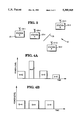
- FIG. 5 is a diagram illustrating transmit packet power levels in successive time intervals.
- FIG. 6 is a block diagram of a portion of station for controlling transmission power levels.
- FIG. 7 is a state diagram illustrating the operation of the circuitry shown in FIG. 6.
- a peer-to-peer wireless LAN (local area network) 10 including a plurality of stations 12, identified individually as stations 12-1 to 12-4 and referred to as stations A, B, C and D, respectively.
- the stations have respective antennas 14 referred to individually as antennas 14-1 to 14-4, and transmission between the stations 12 is effected by transmitting information packets directly over a wireless communication channel from a source station to a destination station.
- antennas 14 referred to individually as antennas 14-1 to 14-4
- transmission between the stations 12 is effected by transmitting information packets directly over a wireless communication channel from a source station to a destination station.
- FIG. 2 the power levels of typical information packets transmitted by station A to stations B, C and D is shown.
- transmission from station A to station B requires a relatively high power level due to the electromagnetic absorbing obstacle 16
- transmission from station A to relatively close station C needs only a relatively low power level
- transmission from station A to station D needs an intermediate power level.
- using the minimum power necessary to achieve effective packet reception has the advantage that less interference is generated, on average, than if a fixed power level dimensioned for the "worst case" maximum distance were employed. It will also be appreciated that for stations powered by batteries, battery power savings are achieved.
- a central star wireless LAN 20 including a plurality of stations 22, identified individually as stations 22-1 to 22-4 and referred to as stations E, F, G and H, respectively.
- stations H which is referred as the hub station.
- the stations have respective antennas 24, referred to individually as antennas 24-1 to 24-4.
- An electromagnetic absorbing obstacle 26 is shown, as in FIG. 1, by a wavy line.
- the stations E, F and G communicate with one another via the hub station H.
- the hub station H transmits information packets to destination stations E, F and G with power levels dependent on the destination station distance and quality of the transmission path as shown in FIG. 4A.
- each station E, F and G uses individually only one power level, as shown for example for station G in FIG. 4B for transmissions from station G to the hub station H, regardless of which station is the ultimate destination station, although the power level may be different for different stations.
- FIG. 5 shows a diagram of power levels of packets P1 through P6 transmitted by a typical station in a wireless LAN assumed to be station A in the LAN 10, FIG. 1.
- some predetermined power level which may be set, for example by government regulatory authorities
- the present invention makes use of the "busty" nature of packet transmissions, that is, a station uses the wireless transmissions medium sporadically, with significant idle periods between transmitted packets.
- a fixed average power value P o is assumed as a basis.
- a succession of equal length time intervals T, having durations substantially greater than a typical packet duration is established at the station. Two such time intervals T are shown in FIG. 5. Then,
- I o is maximum transmitted energy in an interval T which ensures that the power level P o is not exceeded when averaged over the interval.
- P x is the power level at which a typical packet X is transmitted
- d x is the duration of packet X
- I x is the energy contained in packet X.
- packet transmissions are controlled in the station, such that the average power level for transmitted packets does not exceed P o , averaged over each interval T.
- the power level of an individual packet may possibly exceed P o , provided that average power level over the interval T does not exceed P o
- the time intervals T may have a duration of about 100 milliseconds whereas typical information packets have a duration in the range of from about 1 millisecond to about 3 milliseconds.
- a packet source interface 50 stores packets to be transmitted. Each packet has a priority associated therewith, a packet priority control circuit 54 determining which packet is transmitted to a packet buffer 56.
- the packet buffer 56 is coupled to a destination address buffer 58 and to a packet length buffer 60.
- the destination address buffer 58 is coupled to a packet power data base 62 which is connected to a packet energy calculator 64, which also receives an input from the packet length buffer 60.
- the output of the packet energy calculator 64 is coupled to a level control circuit 66.
- An output of the packet buffer 56 is connected to a modulator 68, which also receives an input from an oscillator 70.
- the output of the modulator 68 is connected to an attenuator 72, which is controlled by the level control circuit 66.
- the output of the attenuator 72 is coupled to a transmitter 74 for transmission over the station antenna 76, such as the antenna 14-1 of station A, FIG. 1.
- the circuitry shown in FIG. 5 operates under the control of state control unit 80, in a manner which will now be described.
- State 1 defines the initial point of time interval T by initiating operation of a timer. In this state, the full transmission energy I is available, since no packets have yet been transmitted. Assuming that the station has at least one packet to be transmitted stored in the packet source interface 50, FIG. 6, State 2 is entered via line 90. In State 2, such packet to be transmitted, or the highest priority packet to be transmitted, selected under the control of the packet priority control circuit 54, is sent to the packet buffer 56. Otherwise, the state machine waits until a packet does arrive or the time interval T expires and a new interval begins, as shown by lines 92, 94.
- the state machine proceeds over line 96 to State 3.
- the power necessary to reach the destination station is determined by storing the destination address in the destination address buffer 58, and accessing the packet power data base 62 which provides the power level P x needed by the transmitting station for packet X to reach its destination station.
- the packet energy needed, I x is calculated in the packet energy calculator 64, utilizing the power level value P x and the packet length d x derived from the packet length buffer 60, using equation (2) above. If the packet energy I x is less than the amount of energy available I T , then the packet is transmitted at the required power level, as determined by the attenuator 72 (FIG.
- State 4 if the time interval T has not expired then the state machine may proceed over line 106 to enter State 2 so that another packet can be loaded into the buffer 56.
- the transmitting station acquires information regarding the reception success of its transmitted packets. The acquisition of such feedback information is well known to those skilled in the art of data communication. This information is applied to, and temporarily stored in, the state control circuit 80, FIG. 6. With this information available, if it is found that the transmitted packet was not correctly received at its destination station, then the state machine enters State 5, over line 108. In State 5, it is known that the packet power value P x stored in the data base 62 (FIG. 6) is no longer valid. Therefore, the packet power value is increased by a predetermined incremental value Q.
- the state machine diagram of FIG. 7 includes operation where the transmission of a packet may commence towards the end of an interval T and continue into the next interval T, such that the total transmitted energy during this latter interval T could be higher than I. Similarly, the transmitted energy during a period with duration T but offset to the original interval T timing could be higher than Io. However, averaging over N intervals T yields a result which ensures an energy less than ((N+1)/N)*I o . In other words, with measurement equipment having an integration time much longer than T, the averaged power level will be less than I o /T. Thus, to ensure that power limit conditions imposed by governmental authorities are met, the value of I o as used in practice should be slightly lower than the required value, dependent on the measurement integration time.
- state control unit 80 is preferably arranged to maintain a count of the number of transmission attempts for each packet, such count being passed to the packet priority control unit 54 for use in determining packet priorities.
Abstract
Description
P.sub.o =I.sub.o /T (1)
I.sub.x =P.sub.x d.sub.x (2)
Claims (8)
Applications Claiming Priority (2)
| Application Number | Priority Date | Filing Date | Title |
|---|---|---|---|
| GB9215619 | 1992-07-23 | ||
| GB929215619A GB9215619D0 (en) | 1992-07-23 | 1992-07-23 | Method and apparatus for transmitting digital data packets on a wireless channel |
Publications (1)
| Publication Number | Publication Date |
|---|---|
| US5390165A true US5390165A (en) | 1995-02-14 |
Family
ID=10719138
Family Applications (1)
| Application Number | Title | Priority Date | Filing Date |
|---|---|---|---|
| US07/986,633 Expired - Lifetime US5390165A (en) | 1992-07-23 | 1992-12-04 | Method and apparatus for transmitting digital data packets on a wireless channel |
Country Status (5)
| Country | Link |
|---|---|
| US (1) | US5390165A (en) |
| EP (1) | EP0583058B1 (en) |
| JP (1) | JP3217549B2 (en) |
| DE (1) | DE69334001T2 (en) |
| GB (1) | GB9215619D0 (en) |
Cited By (26)
| Publication number | Priority date | Publication date | Assignee | Title |
|---|---|---|---|---|
| US5594731A (en) * | 1994-07-29 | 1997-01-14 | International Business Machines Corporation | Access point tracking for mobile wireless network node |
| US6002942A (en) * | 1996-06-28 | 1999-12-14 | Samsung Electronics Co., Ltd. | Method for controlling transmitting power of a mobile station |
| US6044073A (en) * | 1994-04-29 | 2000-03-28 | Lucent Technologies, Inc. | Methods of and devices for enhancing communications that use spread spectrum technology by using variable power techniques |
| AU727198B2 (en) * | 1998-10-26 | 2000-12-07 | Alcatel | A method of transmitting calls in a telecommunications system, in particular a system with moving satellites |
| US6587452B1 (en) * | 1999-01-04 | 2003-07-01 | Golden Bridge Technology, Inc. | High performance signal structure with multiple modulation formats |
| US6791996B1 (en) | 1999-09-22 | 2004-09-14 | Matsushita Electric Industrial Co., Ltd. | Wireless network system and communication method employing both contention mode and contention-free mode |
| US20040185868A1 (en) * | 2002-09-10 | 2004-09-23 | Avinash Jain | System and method for multilevel scheduling |
| US20050004970A1 (en) * | 2003-01-13 | 2005-01-06 | Avinash Jain | System and method for a time-scalable priority-based scheduler |
| US20050013282A1 (en) * | 2003-07-15 | 2005-01-20 | Lott Christopher G. | Cooperative autonomous and scheduled resource allocation for a distributed communication system |
| US20050013271A1 (en) * | 2003-07-15 | 2005-01-20 | Lott Christopher G. | Multiflow reverse link MAC for a communications system |
| US7126913B1 (en) * | 1999-03-01 | 2006-10-24 | Cisco Technology, Inc. | Method and system for managing transmission resources in a wireless communications network |
| US20070248031A1 (en) * | 2006-04-21 | 2007-10-25 | Kddi Corporation | Radio communication apparatus and traffic control method for extending drive-time of battery |
| US20090097412A1 (en) * | 2002-09-10 | 2009-04-16 | Qualcomm Incorporated | System and method for rate assignment |
| US20100070751A1 (en) * | 2008-09-18 | 2010-03-18 | Chee Hoe Chu | Preloader |
| US20100174934A1 (en) * | 2009-01-05 | 2010-07-08 | Qun Zhao | Hibernation or Suspend Using a Non-Volatile-Memory Device |
| US8321706B2 (en) | 2007-07-23 | 2012-11-27 | Marvell World Trade Ltd. | USB self-idling techniques |
| US8327056B1 (en) * | 2007-04-05 | 2012-12-04 | Marvell International Ltd. | Processor management using a buffer |
| US8443187B1 (en) | 2007-04-12 | 2013-05-14 | Marvell International Ltd. | Authentication of computing devices in server based on mapping between port identifier and MAC address that allows actions-per-group instead of just actions-per-single device |
| US8510560B1 (en) | 2008-08-20 | 2013-08-13 | Marvell International Ltd. | Efficient key establishment for wireless networks |
| US9141394B2 (en) | 2011-07-29 | 2015-09-22 | Marvell World Trade Ltd. | Switching between processor cache and random-access memory |
| US9436629B2 (en) | 2011-11-15 | 2016-09-06 | Marvell World Trade Ltd. | Dynamic boot image streaming |
| US9575768B1 (en) | 2013-01-08 | 2017-02-21 | Marvell International Ltd. | Loading boot code from multiple memories |
| US9736801B1 (en) | 2013-05-20 | 2017-08-15 | Marvell International Ltd. | Methods and apparatus for synchronizing devices in a wireless data communication system |
| US9836306B2 (en) | 2013-07-31 | 2017-12-05 | Marvell World Trade Ltd. | Parallelizing boot operations |
| US9860862B1 (en) | 2013-05-21 | 2018-01-02 | Marvell International Ltd. | Methods and apparatus for selecting a device to perform shared functionality in a deterministic and fair manner in a wireless data communication system |
| US10979412B2 (en) | 2016-03-08 | 2021-04-13 | Nxp Usa, Inc. | Methods and apparatus for secure device authentication |
Families Citing this family (1)
| Publication number | Priority date | Publication date | Assignee | Title |
|---|---|---|---|---|
| KR100720840B1 (en) * | 1999-01-13 | 2007-05-25 | 코닌클리케 필립스 일렉트로닉스 엔.브이. | A wireless local area networkLAN and a method of operating the LAN |
Citations (6)
| Publication number | Priority date | Publication date | Assignee | Title |
|---|---|---|---|---|
| US4504946A (en) * | 1982-06-11 | 1985-03-12 | Rca Corporation | Time division multiple access communication systems |
| US4613990A (en) * | 1984-06-25 | 1986-09-23 | At&T Bell Laboratories | Radiotelephone transmission power control |
| US4783780A (en) * | 1985-07-09 | 1988-11-08 | U.S. Philips Corp. | Method and apparatus for selecting a free channel in a mobile radio system |
| US4811421A (en) * | 1986-03-14 | 1989-03-07 | Christophe Havel | Transmission power control device in a radio communication transmitting/receiving station |
| US4816825A (en) * | 1987-02-27 | 1989-03-28 | Zenith Electronics Corporation | Method and apparatus for power level control in area networks |
| US4905235A (en) * | 1987-01-16 | 1990-02-27 | Nec Corporation | TDMA system capable of individually controlling electric power of bursts |
Family Cites Families (1)
| Publication number | Priority date | Publication date | Assignee | Title |
|---|---|---|---|---|
| US4995055A (en) * | 1988-06-16 | 1991-02-19 | Hughes Aircraft Company | Time shared very small aperture satellite terminals |
-
1992
- 1992-07-23 GB GB929215619A patent/GB9215619D0/en active Pending
- 1992-12-04 US US07/986,633 patent/US5390165A/en not_active Expired - Lifetime
-
1993
- 1993-06-10 DE DE69334001T patent/DE69334001T2/en not_active Expired - Lifetime
- 1993-06-10 EP EP93304528A patent/EP0583058B1/en not_active Expired - Lifetime
- 1993-06-30 JP JP18313893A patent/JP3217549B2/en not_active Expired - Lifetime
Patent Citations (6)
| Publication number | Priority date | Publication date | Assignee | Title |
|---|---|---|---|---|
| US4504946A (en) * | 1982-06-11 | 1985-03-12 | Rca Corporation | Time division multiple access communication systems |
| US4613990A (en) * | 1984-06-25 | 1986-09-23 | At&T Bell Laboratories | Radiotelephone transmission power control |
| US4783780A (en) * | 1985-07-09 | 1988-11-08 | U.S. Philips Corp. | Method and apparatus for selecting a free channel in a mobile radio system |
| US4811421A (en) * | 1986-03-14 | 1989-03-07 | Christophe Havel | Transmission power control device in a radio communication transmitting/receiving station |
| US4905235A (en) * | 1987-01-16 | 1990-02-27 | Nec Corporation | TDMA system capable of individually controlling electric power of bursts |
| US4816825A (en) * | 1987-02-27 | 1989-03-28 | Zenith Electronics Corporation | Method and apparatus for power level control in area networks |
Cited By (43)
| Publication number | Priority date | Publication date | Assignee | Title |
|---|---|---|---|---|
| US6044073A (en) * | 1994-04-29 | 2000-03-28 | Lucent Technologies, Inc. | Methods of and devices for enhancing communications that use spread spectrum technology by using variable power techniques |
| US5594731A (en) * | 1994-07-29 | 1997-01-14 | International Business Machines Corporation | Access point tracking for mobile wireless network node |
| US6002942A (en) * | 1996-06-28 | 1999-12-14 | Samsung Electronics Co., Ltd. | Method for controlling transmitting power of a mobile station |
| AU727198B2 (en) * | 1998-10-26 | 2000-12-07 | Alcatel | A method of transmitting calls in a telecommunications system, in particular a system with moving satellites |
| US6587452B1 (en) * | 1999-01-04 | 2003-07-01 | Golden Bridge Technology, Inc. | High performance signal structure with multiple modulation formats |
| US7126913B1 (en) * | 1999-03-01 | 2006-10-24 | Cisco Technology, Inc. | Method and system for managing transmission resources in a wireless communications network |
| US6791996B1 (en) | 1999-09-22 | 2004-09-14 | Matsushita Electric Industrial Co., Ltd. | Wireless network system and communication method employing both contention mode and contention-free mode |
| US7457306B2 (en) | 1999-09-22 | 2008-11-25 | Matsushita Electric Industrial Co., Ltd. | Wireless network system and communication method employing both contention mode and contention-free mode |
| US20040185868A1 (en) * | 2002-09-10 | 2004-09-23 | Avinash Jain | System and method for multilevel scheduling |
| US8787180B2 (en) | 2002-09-10 | 2014-07-22 | Qualcomm Incorporated | System and method for rate assignment |
| US8504054B2 (en) | 2002-09-10 | 2013-08-06 | Qualcomm Incorporated | System and method for multilevel scheduling |
| US20090097412A1 (en) * | 2002-09-10 | 2009-04-16 | Qualcomm Incorporated | System and method for rate assignment |
| US8165148B2 (en) * | 2003-01-13 | 2012-04-24 | Qualcomm Incorporated | System and method for rate assignment |
| TWI381680B (en) * | 2003-01-13 | 2013-01-01 | Qualcomm Inc | System and method for a time-scalable priority-based scheduler |
| US20050004970A1 (en) * | 2003-01-13 | 2005-01-06 | Avinash Jain | System and method for a time-scalable priority-based scheduler |
| US20050013271A1 (en) * | 2003-07-15 | 2005-01-20 | Lott Christopher G. | Multiflow reverse link MAC for a communications system |
| US7933235B2 (en) * | 2003-07-15 | 2011-04-26 | Qualcomm Incorporated | Multiflow reverse link MAC for a communications system |
| US8000284B2 (en) | 2003-07-15 | 2011-08-16 | Qualcomm Incorporated | Cooperative autonomous and scheduled resource allocation for a distributed communication system |
| US20050013282A1 (en) * | 2003-07-15 | 2005-01-20 | Lott Christopher G. | Cooperative autonomous and scheduled resource allocation for a distributed communication system |
| US7889688B2 (en) * | 2006-04-21 | 2011-02-15 | Kddi Corporation | Radio communication apparatus and traffic control method for extending drive-time of battery |
| US20070248031A1 (en) * | 2006-04-21 | 2007-10-25 | Kddi Corporation | Radio communication apparatus and traffic control method for extending drive-time of battery |
| US8843686B1 (en) | 2007-04-05 | 2014-09-23 | Marvell International Ltd. | Processor management using a buffer |
| US8327056B1 (en) * | 2007-04-05 | 2012-12-04 | Marvell International Ltd. | Processor management using a buffer |
| US8443187B1 (en) | 2007-04-12 | 2013-05-14 | Marvell International Ltd. | Authentication of computing devices in server based on mapping between port identifier and MAC address that allows actions-per-group instead of just actions-per-single device |
| US9253175B1 (en) | 2007-04-12 | 2016-02-02 | Marvell International Ltd. | Authentication of computing devices using augmented credentials to enable actions-per-group |
| US8839016B2 (en) | 2007-07-23 | 2014-09-16 | Marvell World Trade Ltd. | USB self-idling techniques |
| US8321706B2 (en) | 2007-07-23 | 2012-11-27 | Marvell World Trade Ltd. | USB self-idling techniques |
| US8510560B1 (en) | 2008-08-20 | 2013-08-13 | Marvell International Ltd. | Efficient key establishment for wireless networks |
| US9769653B1 (en) | 2008-08-20 | 2017-09-19 | Marvell International Ltd. | Efficient key establishment for wireless networks |
| US8296555B2 (en) | 2008-09-18 | 2012-10-23 | Marvell World Trade Ltd. | Preloader |
| US9652249B1 (en) | 2008-09-18 | 2017-05-16 | Marvell World Trade Ltd. | Preloading an application while an operating system loads |
| US8688968B2 (en) | 2008-09-18 | 2014-04-01 | Marvell World Trade Ltd. | Preloading an application while an operating system loads |
| US20100070751A1 (en) * | 2008-09-18 | 2010-03-18 | Chee Hoe Chu | Preloader |
| US8443211B2 (en) | 2009-01-05 | 2013-05-14 | Marvell World Trade Ltd. | Hibernation or suspend using a non-volatile-memory device |
| US20100174934A1 (en) * | 2009-01-05 | 2010-07-08 | Qun Zhao | Hibernation or Suspend Using a Non-Volatile-Memory Device |
| US9141394B2 (en) | 2011-07-29 | 2015-09-22 | Marvell World Trade Ltd. | Switching between processor cache and random-access memory |
| US9436629B2 (en) | 2011-11-15 | 2016-09-06 | Marvell World Trade Ltd. | Dynamic boot image streaming |
| US10275377B2 (en) | 2011-11-15 | 2019-04-30 | Marvell World Trade Ltd. | Dynamic boot image streaming |
| US9575768B1 (en) | 2013-01-08 | 2017-02-21 | Marvell International Ltd. | Loading boot code from multiple memories |
| US9736801B1 (en) | 2013-05-20 | 2017-08-15 | Marvell International Ltd. | Methods and apparatus for synchronizing devices in a wireless data communication system |
| US9860862B1 (en) | 2013-05-21 | 2018-01-02 | Marvell International Ltd. | Methods and apparatus for selecting a device to perform shared functionality in a deterministic and fair manner in a wireless data communication system |
| US9836306B2 (en) | 2013-07-31 | 2017-12-05 | Marvell World Trade Ltd. | Parallelizing boot operations |
| US10979412B2 (en) | 2016-03-08 | 2021-04-13 | Nxp Usa, Inc. | Methods and apparatus for secure device authentication |
Also Published As
| Publication number | Publication date |
|---|---|
| EP0583058B1 (en) | 2006-03-29 |
| DE69334001T2 (en) | 2007-01-25 |
| JP3217549B2 (en) | 2001-10-09 |
| GB9215619D0 (en) | 1992-09-09 |
| DE69334001D1 (en) | 2006-05-18 |
| EP0583058A3 (en) | 1998-03-18 |
| JPH06104895A (en) | 1994-04-15 |
| EP0583058A2 (en) | 1994-02-16 |
Similar Documents
| Publication | Publication Date | Title |
|---|---|---|
| US5390165A (en) | Method and apparatus for transmitting digital data packets on a wireless channel | |
| US4574378A (en) | Multiple access system and method | |
| US3925782A (en) | Adaptive RF power output control for net radios | |
| US5511079A (en) | Apparatus and method for controlling forward error correction encoding in a very small aperture terminal | |
| US4709401A (en) | Method of setting radio transmitters for synchronous radio transmission | |
| EP0210811B1 (en) | Time division multiple access radio communication system | |
| US6175744B1 (en) | Transmission power control method and apparatus for mobile communication system | |
| EP0960490B1 (en) | Method for acquisition and synchronization of terminals in a wireless tdma system | |
| EP0579372B1 (en) | Power control method in a wireless communication system | |
| EP0969606B1 (en) | Dynamic power control with adaptive reference level | |
| US4686672A (en) | TDMA communications apparatus having adaptive burst duration | |
| CA2126507A1 (en) | Remote data acquisition and communication system | |
| KR920702111A (en) | How to meet the traffic and performance requirements of mobile communication wireless system | |
| EP0987841A3 (en) | A satellite communications system with power control | |
| EP1125375B1 (en) | Power control method in a communication system | |
| US6845085B1 (en) | Synchronization method for a processing communication satellite | |
| US5930268A (en) | Transceiver and associated method for surviving fades | |
| US20050054288A1 (en) | Method for dynamic load management of random access shared communications channels | |
| CA1254313A (en) | Station of a tdma communication network capable of quickly changing communication traffic without causing an overlap between transmission bursts | |
| EP0240821A3 (en) | Method for the transmission of digital signals in a mobile radio system | |
| US5905720A (en) | Method and apparatus for traffic management of inbound communications in a radio communication system | |
| US20130294224A1 (en) | Transmit and admission control for cdma satellite communication system | |
| EP1443679A3 (en) | Method and base station for transmitting information on a common packet data channel | |
| JP2982724B2 (en) | Transmission output power control method for multi-way multiplex communication system | |
| US5926746A (en) | Frequency and other parameter adjustment using training channel |
Legal Events
| Date | Code | Title | Description |
|---|---|---|---|
| AS | Assignment |
Owner name: NCR CORPORATION, OHIO Free format text: ASSIGNMENT OF ASSIGNORS INTEREST;ASSIGNOR:TUCH, BRUCE T.;REEL/FRAME:007183/0141 Effective date: 19921120 |
|
| STCF | Information on status: patent grant |
Free format text: PATENTED CASE |
|
| FEPP | Fee payment procedure |
Free format text: PAYOR NUMBER ASSIGNED (ORIGINAL EVENT CODE: ASPN); ENTITY STATUS OF PATENT OWNER: LARGE ENTITY Free format text: PAYER NUMBER DE-ASSIGNED (ORIGINAL EVENT CODE: RMPN); ENTITY STATUS OF PATENT OWNER: LARGE ENTITY |
|
| FEPP | Fee payment procedure |
Free format text: PAYOR NUMBER ASSIGNED (ORIGINAL EVENT CODE: ASPN); ENTITY STATUS OF PATENT OWNER: LARGE ENTITY |
|
| FEPP | Fee payment procedure |
Free format text: PAYOR NUMBER ASSIGNED (ORIGINAL EVENT CODE: ASPN); ENTITY STATUS OF PATENT OWNER: LARGE ENTITY Free format text: PAYER NUMBER DE-ASSIGNED (ORIGINAL EVENT CODE: RMPN); ENTITY STATUS OF PATENT OWNER: LARGE ENTITY |
|
| FPAY | Fee payment |
Year of fee payment: 4 |
|
| FPAY | Fee payment |
Year of fee payment: 8 |
|
| SULP | Surcharge for late payment |
Year of fee payment: 7 |
|
| AS | Assignment |
Owner name: AGERE SYSTEMS INC., PENNSYLVANIA Free format text: ASSIGNMENT OF ASSIGNORS INTEREST;ASSIGNORS:AT&T CORP.;LUCENT TECHNOLOGIES INC.;REEL/FRAME:015829/0161;SIGNING DATES FROM 19960329 TO 20020531 |
|
| FPAY | Fee payment |
Year of fee payment: 12 |
|
| AS | Assignment |
Owner name: AT&T CORP., NEW YORK Free format text: ASSIGNMENT OF ASSIGNORS INTEREST;ASSIGNOR:NCR CORPORATION;REEL/FRAME:020773/0814 Effective date: 19960329 Owner name: AGERE SYSTEMS INC., PENNSYLVANIA Free format text: ASSIGNMENT OF ASSIGNORS INTEREST;ASSIGNOR:LUCENT TECHNOLOGIES INC.;REEL/FRAME:020773/0752 Effective date: 20020531 Owner name: LUCENT TECHNOLOGIES INC., NEW JERSEY Free format text: ASSIGNMENT OF ASSIGNORS INTEREST;ASSIGNOR:AT&T CORP.;REEL/FRAME:020773/0807 Effective date: 19960329 |