US5390118A - Automatic lateral guidance control system - Google Patents
Automatic lateral guidance control system Download PDFInfo
- Publication number
- US5390118A US5390118A US08/156,944 US15694493A US5390118A US 5390118 A US5390118 A US 5390118A US 15694493 A US15694493 A US 15694493A US 5390118 A US5390118 A US 5390118A
- Authority
- US
- United States
- Prior art keywords
- vehicle
- markers
- road
- distance
- control signal
- Prior art date
- Legal status (The legal status is an assumption and is not a legal conclusion. Google has not performed a legal analysis and makes no representation as to the accuracy of the status listed.)
- Expired - Fee Related
Links
- 239000003550 marker Substances 0.000 claims description 85
- 238000000034 method Methods 0.000 claims description 30
- 238000012552 review Methods 0.000 claims description 23
- 230000004044 response Effects 0.000 claims description 13
- 230000003287 optical effect Effects 0.000 claims description 7
- 238000012545 processing Methods 0.000 claims description 5
- 238000005259 measurement Methods 0.000 description 20
- 230000006870 function Effects 0.000 description 11
- 238000010586 diagram Methods 0.000 description 8
- 230000001939 inductive effect Effects 0.000 description 8
- 230000035484 reaction time Effects 0.000 description 8
- 230000008569 process Effects 0.000 description 6
- 238000013528 artificial neural network Methods 0.000 description 3
- 230000008901 benefit Effects 0.000 description 3
- 238000004364 calculation method Methods 0.000 description 3
- 230000001965 increasing effect Effects 0.000 description 3
- 239000000463 material Substances 0.000 description 3
- 238000013461 design Methods 0.000 description 2
- 238000012423 maintenance Methods 0.000 description 2
- 230000035945 sensitivity Effects 0.000 description 2
- 230000008859 change Effects 0.000 description 1
- 238000006243 chemical reaction Methods 0.000 description 1
- 238000007796 conventional method Methods 0.000 description 1
- 125000004122 cyclic group Chemical group 0.000 description 1
- 238000001514 detection method Methods 0.000 description 1
- 238000006073 displacement reaction Methods 0.000 description 1
- 238000005516 engineering process Methods 0.000 description 1
- 239000012770 industrial material Substances 0.000 description 1
- 238000009434 installation Methods 0.000 description 1
- 238000012804 iterative process Methods 0.000 description 1
- 238000012886 linear function Methods 0.000 description 1
- 238000005007 materials handling Methods 0.000 description 1
- 230000003340 mental effect Effects 0.000 description 1
- 238000012986 modification Methods 0.000 description 1
- 230000004048 modification Effects 0.000 description 1
- 230000037361 pathway Effects 0.000 description 1
- 239000004065 semiconductor Substances 0.000 description 1
- 230000003068 static effect Effects 0.000 description 1
- 238000012546 transfer Methods 0.000 description 1
Images


Classifications
-
- B—PERFORMING OPERATIONS; TRANSPORTING
- B62—LAND VEHICLES FOR TRAVELLING OTHERWISE THAN ON RAILS
- B62D—MOTOR VEHICLES; TRAILERS
- B62D1/00—Steering controls, i.e. means for initiating a change of direction of the vehicle
- B62D1/24—Steering controls, i.e. means for initiating a change of direction of the vehicle not vehicle-mounted
- B62D1/28—Steering controls, i.e. means for initiating a change of direction of the vehicle not vehicle-mounted non-mechanical, e.g. following a line or other known markers
-
- G—PHYSICS
- G01—MEASURING; TESTING
- G01S—RADIO DIRECTION-FINDING; RADIO NAVIGATION; DETERMINING DISTANCE OR VELOCITY BY USE OF RADIO WAVES; LOCATING OR PRESENCE-DETECTING BY USE OF THE REFLECTION OR RERADIATION OF RADIO WAVES; ANALOGOUS ARRANGEMENTS USING OTHER WAVES
- G01S17/00—Systems using the reflection or reradiation of electromagnetic waves other than radio waves, e.g. lidar systems
- G01S17/88—Lidar systems specially adapted for specific applications
- G01S17/93—Lidar systems specially adapted for specific applications for anti-collision purposes
- G01S17/931—Lidar systems specially adapted for specific applications for anti-collision purposes of land vehicles
-
- G—PHYSICS
- G05—CONTROLLING; REGULATING
- G05D—SYSTEMS FOR CONTROLLING OR REGULATING NON-ELECTRIC VARIABLES
- G05D1/00—Control of position, course or altitude of land, water, air, or space vehicles, e.g. automatic pilot
- G05D1/02—Control of position or course in two dimensions
- G05D1/021—Control of position or course in two dimensions specially adapted to land vehicles
- G05D1/0231—Control of position or course in two dimensions specially adapted to land vehicles using optical position detecting means
- G05D1/0234—Control of position or course in two dimensions specially adapted to land vehicles using optical position detecting means using optical markers or beacons
- G05D1/0236—Control of position or course in two dimensions specially adapted to land vehicles using optical position detecting means using optical markers or beacons in combination with a laser
-
- G—PHYSICS
- G05—CONTROLLING; REGULATING
- G05D—SYSTEMS FOR CONTROLLING OR REGULATING NON-ELECTRIC VARIABLES
- G05D1/00—Control of position, course or altitude of land, water, air, or space vehicles, e.g. automatic pilot
- G05D1/02—Control of position or course in two dimensions
- G05D1/021—Control of position or course in two dimensions specially adapted to land vehicles
- G05D1/0255—Control of position or course in two dimensions specially adapted to land vehicles using acoustic signals, e.g. ultra-sonic singals
-
- G—PHYSICS
- G05—CONTROLLING; REGULATING
- G05D—SYSTEMS FOR CONTROLLING OR REGULATING NON-ELECTRIC VARIABLES
- G05D1/00—Control of position, course or altitude of land, water, air, or space vehicles, e.g. automatic pilot
- G05D1/02—Control of position or course in two dimensions
- G05D1/021—Control of position or course in two dimensions specially adapted to land vehicles
- G05D1/0268—Control of position or course in two dimensions specially adapted to land vehicles using internal positioning means
- G05D1/0272—Control of position or course in two dimensions specially adapted to land vehicles using internal positioning means comprising means for registering the travel distance, e.g. revolutions of wheels
Definitions
- the present invention generally relates to an automatic lateral guidance control system for controlling the direction of a moving vehicle along a predetermined path, and more particularly, to an improved vehicle controller for use in an automatic lateral guidance control system for controlling the direction of a motor vehicle on a highway.
- So-called "Automated Highways" are presently being contemplated, which will include vehicular-based systems that will automatically control the motor vehicle's speed, steering and braking, in order to substitute for the driver as a prime source of control over the vehicle.
- the expected advantages of such systems will be to improve the overall flow of traffic and increase highway safety.
- the present invention is directed to such a vehicular-based system for automatically controlling vehicle direction, which accurately guides a vehicle along a path while providing a comfortable ride for passengers.
- a variety of conventional guidance systems are used for controlling the movement of vehicles travelling along a predetermined path such as, for example, robotic material handling guidance systems.
- a "robotic vehicle” for moving materials between separate points in a warehouse or storage area without human intervention, is provided with an automated steering control system that utilizes an inductive sensor mounted near the bottom of the vehicle in order to sense a current passing through a thin wire disposed either at or below the surface of a predetermined pathway.
- the inductive sensor senses the magnetic field radiated from the wire and, using conventional phase-detection techniques, produces an output signal which indicates the extent to which the vehicle has drifted laterally from the desired course.
- the output signals from the sensor are provided to a vehicle control circuit that typically converts the sensor's output signal into control error signals which are used to direct the vehicle back on course.
- a series of spaced-apart responders are disposed in a single row parallel to the centerline of the roadway, or in a pair of rows on opposite sides of the centerline, for reflecting radiant energy from the laser transmitter back to the receiver.
- the laser transmitter radiates two overlapping beams which are amplitude-modulated by sine waves that are 180 degrees out of phase.
- the receiver merges the two reflected beams into a single beam that is subject to a cyclic translatory shift in amplitude.
- the amplitude shift is translated into a voltage whose amplitude varies in accordance with the position of the vehicle.
- a comparison of the phase differences between the transmitted and reflected beams provides a determination of the vehicle's location with respect to the reflectors.
- the use of such a system typically requires the use of a high powered laser transmitter, which can have a prohibitively high cost.
- the conventional laser-controlled, automatic guidance systems have limited tracking performance or accuracy with respect to controlling the vehicle's direction, because such systems do not take into account the vehicle's speed.
- the reaction time needed to steer the vehicle in response to sensed changes in the direction of the road increases as the vehicle's speed increases.
- the conventional automatic guidance systems for motor vehicles may be considered "look-ahead" systems, the reaction time for the conventional systems is still limited at the higher vehicle speeds.
- the present invention provides a novel arrangement for a "look-ahead" automatic lateral guidance control system that accounts for the speed of the vehicle and thereby increases the tracking performance and accuracy of the system, while providing a comfortable travelling environment.
- an object of the present invention to provide an improved automatic guidance control system having an arrangement for automatically guiding the direction of a moving vehicle.
- an improved automatic guidance control system for guiding moving vehicles which includes a sensing subsystem for viewing an area in front of a vehicle, a plurality of energy radiating or energy reflective devices disposed adjacent a predetermined length of road an apparatus for translating the radiated or reflected information from the viewed area into coordinate data representing an approximation of the predetermined path along the road, and a vehicle controller for determining the vehicle's heading with respect to the approximated path and providing an output control signal to correct the vehicle's heading with respect to the approximated path.
- the system uses past and present marker and vehicle position data to calculate a predetermined path for the vehicle. Gain factors and human engineering factors are determined to maximize comfort to passengers of the vehicle and to optimize performance of the system.
- FIG. 1 is a schematic diagram of an improved automatic lateral guidance control system in accordance with a preferred embodiment of the present invention.
- FIG. 2 is an overall functional block diagram of the improved automatic lateral guidance control system of FIG. 1.
- FIG. 3 illustrates a sequence of steps which may be performed to operate the improved automatic lateral guidance control system of FIGS. 1 and 2.
- FIG. 4 is a schematic diagram illustrating a set of steps in FIG. 3 for calculating relative vehicle and marker position measurements.
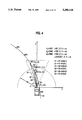
- FIG. 5 illustrates a set of steps in FIG. 3 for calculating past and present relative vehicle and marker position measurements.
- FIG. 6 illustrates the conversion of the past position measurements as shown in FIG. 5 from one coordinate system to another.
- FIG. 7 is a block diagram of an improved automatic lateral guidance control system in accordance with a second embodiment of the present invention.
- FIG. 8 illustrates the improved automatic lateral guidance control system of FIG. 7 operating with respect to a predetermined path.
- FIG. 9 illustrates a sequence of steps which may be performed to operate the improved automatic lateral guidance control system illustrated in FIGS. 7 and 8.
- FIG. 10 illustrates an improved automatic lateral guidance control system in accordance with a third embodiment of the present invention.
- FIG. 11 illustrates a sequence of steps which may be performed to operate the improved automatic lateral guidance control system of FIG. 10.
- FIG. 12 illustrates various gain schedules for use with the automatic lateral guidance control systems of FIGS. 7, 8, 9, 10 and 11.
- FIG. 13 schematically illustrates a use of a comfort factor in accordance with the present invention.
- FIG. 14 schematically illustrates a relationship between the comfort factor of FIG. 13 and the curvature of the road.
- FIG. 1 is a schematic diagram of an improved automatic lateral guidance control system in accordance with a preferred embodiment of the present invention.
- Vehicle 8 is equipped with automatic lateral guidance control system 10 which automatically guides the heading or forward direction of vehicle 8 with respect to actual path 28.
- a plurality of reflectors 34 may be disposed adjacent to or along path 28.
- retroflectors which are well known in the art may be utilized for reflectors 34 in a preferred embodiment, the present invention is not intended to be limited thereto, and any suitable optical reflecting medium may be substituted for reflectors 34.
- a series of painted, reflective stripes may be disposed along (i.e., following the length of) path 28.
- Actual path 28 may comprise for example, a roadway, a lane of a highway or any other like predetermined route.
- Vehicle 8 may comprise for example, an automobile, truck, bus, or any other suitable type of mobile vehicle for travelling along a predetermined route such as path 28.
- Automatic lateral guidance control system 10 guides vehicle 8 in a generally forward direction along the forward, centerline axis of vehicle 8, which axis is hereinafter defined as vehicle heading 20.
- Automatic lateral guidance control system 10 adjusts the course of vehicle 8 in order to cause the vehicle to follow path 28.
- automatic lateral guidance control system 10 adjusts the course of vehicle 8 by determining the angular displacement between vehicle heading 20 and a straight line drawn from the front of vehicle 8 to selected target point 24, whereby target point 24 is a point located on ideal road geometry 29.
- ideal road geometry 29 is a calculated approximation of actual path 28.
- Vehicle 8 is then steered with respect to selected target point 24.
- the process of determining the vehicle's heading with respect to a selected target point on ideal road geometry 29, and correcting the vehicle's heading is an iterative process which is performed by a sequence of steps programmed into a microcomputer. Consequently, the process of determining and correcting the vehicle's heading is continuously repeated as the vehicle travels along the roadway.
- ideal road geometry 29 is hereinafter defined to be an accurate approximation of the curvature of actual path 28. In essence, road geometry 29 is substantially equivalent to actual path 28. A preferred technique for calculating ideal road geometry 29 is discussed in substantive detail below.
- FIG. 2 is an overall functional block diagram of the improved automatic lateral guidance control system of FIG. 1.
- Automatic lateral guidance control system 10 comprises vehicle speed sensor 32, preview sensors 16, yaw rate sensor 13, signal processor 14, microcontroller 12, and steering servo system 18.
- Microcontroller 12 comprises a microprocessor, read only memory (ROM), read access memory (RAM), and input/output ports (I/O ports). It should be understood that microcontroller 12 may also comprise any additional circuitry, such as A/D and D/A converters, combinational logic circuitry, latching circuitry, etc., that may be necessary for the operation and interconnection of microcontroller 12 with respect to the components of automatic lateral guidance control system 10. All of the above-described components of microcontroller 12 may be located on an individual semiconductor chip.
- microcontroller 12 may comprise, for example, a Motorola MC68HC705C8 type microcontroller. Alternatively, a Digital Signal Processing Board, such as for example, a Texas Instruments TMS 320C30, may be utilized. Although the structure and operation of a specific type of microcontroller is described herein for illustrative purposes with respect to a preferred embodiment, the type of microcontroller selected is not critical to making and using the present invention, and the present invention is not intended to be limited thereto. Any suitable microcontroller or similarly constructed apparatus for performing the operations of the present invention may be substituted herein.
- vehicle speed sensor 32 is coupled to microcontroller 12 and to signal processor 14 to provide a measurement of the speed of vehicle 8.
- Vehicle speed sensor 32 may comprise any of a number of conventional speed sensors for use in a motor vehicle such as, for example, a speed sensor connected to a wheel of vehicle 8.
- Preview sensors 16 are coupled to an input of signal processor 14 and provide measurements of the relative position, including distance and angle, of vehicle 8 with respect to at least one of reflectors 34 located along path 28.
- Yaw rate sensor 15 is coupled to an input of the signal processor 14 and provides measurements of the vehicle yaw rate information.
- An output from signal processor 14 is coupled to an input of microcontroller 12.
- Steering servo system 18 is coupled to microcontroller 12 and may, for example, comprise a conventional steering control system including a steering controller and steering actuator. Steering servo system 18 operates to change the direction of vehicle 8 in response to control signals generated by microcontroller 12, in order to maintain the heading of vehicle 8 with respect to path 28.
- Preview sensors 16, which are electrically coupled to microcontroller 12 and signal processor 14, may be mounted on a right front portion of vehicle 8, for example, for use in a country (such as the United States) where vehicles typically travel on the right hand side of the road. Thus, preview sensors 16 may scan reflectors or other types of road markers disposed at or near the right hand side of the roadway. It is also envisioned that preview sensors 16 may be mounted in the center front portion of vehicle 8, in order to scan both sides of the roadway. Preview sensors 16 may comprise, for example, a laser transmitter/receiver (radar) system or other optical sensing apparatus, such as a video camera.
- radar laser transmitter/receiver
- preview sensors 16 are described herein with respect to an optical sensing apparatus for illustrative purposes only, but the present invention is not intended to be limited thereto.
- Preview sensors 16 also may include other suitable sensing devices for determining angle and distance to each of a series of "markers" disposed adjacent to a roadway such as, for example, a receiver operating at radio-frequencies (RF) that detects and processes radiated signals from a series of RF "beacon” transmitters disposed adjacent to the road, or any other suitable sensing apparatus for sensing the distance and angle with respect to vehicle 8 and each of a series of energy reflecting or energy radiating "markers.”
- RF radio-frequencies
- the term “reflector” refers to any reflective medium for reflecting light energy.
- the term “marker” more broadly may refer either to an energy reflecting device or energy radiating device disposed adjacent to a roadway.
- the term “marker” may also refer to a section of material radiating a static magnetic field.
- each transmitter of preview sensors 16 scans or radiates a beam of light to at least one of reflectors 34.
- the associated laser receiver of preview sensors 16 receives a reflected signal from each of scanned reflectors 34.
- Preview sensors 16 measure the distance and angle between each of scanned reflectors 34 and the heading of vehicle 8. This measurement information is provided to microcontroller 12 in order to determine the location of each of scanned reflectors 34 with respect to vehicle 8. This measurement information may be computed by preview sensors 16 by measuring a phase difference between the transmitted and received laser beams, or by using a pulsed laser beam and measuring propagation time to the reflector and back.
- FIG. 3 illustrates a sequence of steps which may be performed to operate the improved automatic lateral guidance control system of FIGS. 1 and 2.
- this sequence of steps may be performed by programming microcontroller 12 using well-known programming techniques. Such programming techniques would be known to a computer programmer of ordinary skill.
- preview sensors 16 measure the distance and angle between each of said reflectors (or markers) 34 and the heading of vehicle 8.
- Yaw rate sensor 15 measures the yaw rate of the vehicle.
- preview sensors 16 scan an area that includes at least three of reflectors 34, although it is within the scope of the invention to scan an area of less than three reflectors.
- the measurement information determining the relative position for each of the three scanned reflectors 34 with respect to vehicle 8 is read into the memory area of microcontroller 12.
- the vehicle speed information is also read into microcontroller 12 and/or signal processor 14 from vehicle speed sensor 32.
- FIG. 4 is a schematic diagram illustrating a set of steps to be performed with respect to block 300 in FIG. 3 for calculating angles and distances to markers.
- preview sensors 16 detect the angles and distances to at least three of reflectors M1, M2 and M3.
- preview sensors 16 provide measurements of angles ⁇ 1, ⁇ 2 and ⁇ 3, and distances d1, d2 and d3 with respect to the scanned three of reflectors M1, M2 and M3.
- the positions of the selected reflectors (or markers) M1, M2 and M3 are (x1, y1), (x2, y2) and (x3, y3). These positions are related to the angle and distance information provided by sensors 16 through the following set of equations:
- the method of estimating road geometry utilizes both past and present relative vehicle and marker positional information in order to improve the system's sensitivity and accuracy.
- solid lines indicate the present position of the vehicle.
- Dashed lines indicate a past position of the vehicle.
- the solid-lined vehicle scans at least three markers (M2, M3 and M4) to locate their positions in the O 2 X 2 Y 2 coordinate system (vehicle-body-fixed coordination).
- the vehicle control system had located the position of marker M1, and had stored its positional information, with respect to the coordinate system O 1 X 1 Y 1 , in RAM (memory) of microcontroller 12.
- this previous marker position M1 is recalled from memory and is converted, in block 304, to a position in the O 2 X 2 Y 2 coordinate system using the vehicle speed information (V x ) and the yaw rate information ( ⁇ ).
- FIG. 6 The coordinate system transfer of previous marker position M1 is shown in detail in FIG. 6.
- the coordinates of a position in the coordinate system O 1 X 1 Y 1 will move a distance of Vx ⁇ t in a direction of ⁇ /2-degrees and with a rotation of ⁇ degrees, where ⁇ is calculated as follows:
- marker positions on the vehicle-body-fixed coordinate system are stored into memory and are used, in block 308, to estimate road geometry in a calculation detailed below (Equations 3 and 4).
- the road geometry is thus estimated using at least four marker positions (M1, M2, M3. M4).
- the invention may be easily modified so that two or more previous marker positions may be stored in the control system memory and used for road geometry estimation. Thus, error due to missing markers is minimized and consequently, the system becomes more accurate, efficient and is more sensitive to changes in road geometry.
- microcontroller 12 calculates ideal road geometry 29 from the angle and distance measurement information obtained from preview sensor 16 and from both present and past marker positions.
- Ideal road geometry 29 is calculated as an accurate approximation of the curvature of path 28 with respect to the portion defined by the selected markers, by using the following equation for a circle:
- ideal road geometry 29 may also be determined by signal processor 14.
- Signal processor 14 may also approximate the curvature of a portion of path 28 which has been scanned by preview sensors 16. Utilizing the angle and distance measurements with respect to scanned markers or reflectors 34, signal processor 14 provides x, y coordinate information with respect to the position and heading of vehicle 8 and path 28, which represents an accurate approximation of the curvature of path 28 (i.e., ideal road geometry).
- An advantage of the approximation technique used in signal processor 14 over conventional techniques is that the calculations for determining the ideal road geometry are performed with the assistance of so-called "neural network" computer technology.
- a set of functions approximating the curvature of path 28 is constructed on a neural network computer, which is typically a general purpose computer. These functions are "learned" by the computer by experimentally constructing functions that satisfy known input and output data.
- Signal processor 14 is programmed with the learned functions developed by the neural network computer. Signal processor 14 then provides coordinate values to microcontroller 12 that allow microcontroller 12 to determine the position and heading of vehicle 8 with respect to the approximated curvature of path 28 (i.e., ideal road geometry) that has been derived by signal processor 14.
- microcontroller 12 may calculate ideal road geometry independently of any information to be provided from signal processor 14, and the use of signal processor 14 is presently considered only as an alternative or possible option for calculating ideal road geometry 29 which is not critical to making or using the present invention.
- microcontroller 12 next determines preview distance 23.
- the determination of preview distance is necessary in order to increase the reaction time available for guidance control system 10 to correct heading angle 22 in response to variations in the curvature of path 28.
- Preview distance 23 is a distance projected from the front of vehicle 8, and is defined as the radius of half-circle 26.
- the length of preview distance 23 is a function of the speed of vehicle 8.
- the actual values for preview distance 23 are determined by experimentation, because the selection of optimum values for preview distance 23 is a trade-off between ride comfort in the vehicle and control system performance. Consequently, the values determined for preview distance 23 must be compatible with both ride comfort and system performance. However, these values may be readily determined by system designers of ordinary skill.
- preview distance 23 must be sufficient to allow automatic lateral guidance control system 10 sufficient reaction time to determine heading angle 22 and to calculate the desired steering angle to be provided to steering servo system 18.
- microcontroller 12 determines target point 24 based on the length of preview distance 23.
- Target point 24 is determined as the intersection of the radius of half-circle 26 (i.e., the length of preview distance 23) with road geometry 29.
- Automatic lateral guidance control system 10 as depicted in FIGS. 1, 2 and 3, is defined as a continuous marker system because target point 24 may occur at any location along calculated road geometry 29. Thus, the target point may intersect a point on the approximated path even though no reflector or marker is actually located at that point.
- the locus of points defined by half-circle 26 is determined by the following equation:
- Target point 24 is the intersection point (x t , Y t ) defined by the solutions to equations (4) and (5) above.
- microcontroller 12 calculates heading angle 22.
- Heading angle 22 is the angle between vehicle heading 20 and a straight line from vehicle 8 to target point 24.
- Heading angle 22 may be calculated according to any well known mathematical technique used for calculating angles.
- heading angle 22 may be calculated with respect to FIG. 4, by the following equation: ##EQU1## where ⁇ is heading angle 22.
- microcontroller 12 calculates the desired steering angle to be provided to steering servo system 18, based on heading angle 22. This step is performed by adjusting heading angle 22 to steer vehicle 8 towards target point 24. Consequently, microcontroller 12 must provide a desired steering angle as an output to steering servo system 18 that causes vehicle 8 to steer in the direction of target point 24. Desired steering angle ⁇ d is calculated from the following equation:
- K is the control gain, or feedback gain, of the system.
- Control gain K is a function of vehicle speed and the curvature of the path being followed.
- the actual values for control gain K can be determined by experimentation, because the selection of optimum values for control gain K is a trade-off between vehicle speed and the curvature of the path being followed. Consequently, the values determined for control gain K must be compatible with vehicle speed and path curvature. However, these values may be readily determined by system designers of ordinary skill.
- FIG. 7 is a block diagram of an improved automatic lateral guidance control system in accordance with a second embodiment of the present invention.
- automatic lateral guidance control system 70 comprises microcontroller 12, preview sensors 16, vehicle speed sensor 32, and steering servo system 18.
- Signal processor 14 which is utilized in the embodiment illustrated by FIGS. 1, 2 and 3, is not utilized in the present embodiment.
- This embodiment provides an alternative structure to automatically guide a vehicle along a predetermined path.
- automatic lateral guidance control system 70 provides a desired steering angle ⁇ d for controlling the heading of vehicle 8, by calculating a heading angle with respect to the position of a discrete reflector.
- the present embodiment is hereinafter called a "discrete marker system" of control, as opposed to the "continuous marker system” disclosed in the first embodiment.
- FIG. 8 illustrates the improved automatic lateral guidance control system of FIG. 7 with vehicle 8 travelling along actual path 28.
- reflectors 34a-e are markers that are disposed at predetermined locations along path 28.
- the distance between each of reflectors 34a-e is a variable highway design constraint.
- the distance between each of reflectors 34a-e is approximately 50 feet in the State of California.
- automatic guidance control system 70 guides vehicle 8 in a generally forward direction along the forward, centerline axis of vehicle 8, which has been previously defined as vehicle heading 20.
- heading angle 42 is determined with respect to reflector 34b
- heading angle 43 is determined with respect to reflector 34c.
- Minimum preview review distance 45 is defined as the radius of circle 50.
- Minimum preview review distance 45 is a distance projected from one of reflectors 34 and is defined as the radius of circle 50.
- the length of minimum preview review distance 45 is a function of the speed of vehicle 8.
- the actual values for minimum preview review distance 45 are determined by experimentation, because the selection of optimum values for minimum preview review distance 45 is a trade-off between ride comfort in the vehicle and control system performance. Consequently, the values determined for minimum preview review distance 45 must be compatible with both ride comfort and system performance. However, these values may be readily determined by system designers of ordinary skill.
- minimum preview review distance 45 must be sufficient to allow automatic guidance control system 70 sufficient reaction time to calculate heading angles 42 and 43, and the desired steering angle ⁇ d to be provided to steering servo system 18.
- FIG. 9 illustrates a sequence of steps which may be performed by microcontroller 12 to operate the improved automatic lateral guidance control system illustrated in FIGS. 7 and 8.
- blocks 602-628 disclose a sequence of steps to be performed by microcontroller 12 in order to calculate a desired steering angle from angle and distance measurements to a discrete marker (reflector 34).
- the angle and distance measurements from reflectors 34 are read in to microcontroller 12 from preview sensors 16.
- Preview sensors 16 measure the distance and angle between each of reflectors 34 and vehicle 8.
- the vehicle speed information from vehicle speed sensor 32 is also read in to microcontroller 12.
- microcontroller 12 determines the length of preview distance 23 as a function of vehicle speed.
- microcontroller 12 selects an initial target marker (reflector 34b in this instance) by selecting a marker having the smallest distance value which is still greater than or equal to the length of preview distance 23.
- microcontroller 12 then calculates heading angle 42. Heading angle 42 is the angle between vehicle heading 20 and a straight line from vehicle 8 to target marker 34b. Heading angle 42 may be calculated using the well-known mathematical techniques as disclosed above with respect to block 314 in FIG. 3.
- microcontroller 12 calculates desired steering angle ⁇ d to be provided to steering servo system 18, based on heading angle 42.
- microcontroller 12 must provide a desired steering angle as an output to steering servo system 18 that causes vehicle 8 to steer in the direction of target marker 34b.
- the desired steering angle is equal to the control gain K times heading angle 42.
- the control gain K is a function of vehicle speed and road curvature and will be described in greater detail below.
- microcontroller 12 determines the next reflector by knowledge of the distance and angle measurements. Then, in block 622, microcontroller 12 determines the magnitude of heading angle 43 (the heading angle with respect to selected target marker 34c). The magnitude of heading angle 43 is then provided for the calculation of desired steering angle in block 626. As shown in FIG. 9, the process of selecting the next target marker and calculating a desired steering angle is then repeated by returning to block 614.
- FIG. 10 illustrates an improved automatic lateral guidance control system in accordance with a third embodiment of the present invention.
- the automatic lateral guidance control system disclosed with respect to the third embodiment comprises the structure of system 70 as shown in FIG. 7.
- FIG. 10 illustrates the improved automatic lateral guidance control system of FIG. 7 with vehicle 8 travelling along actual path 28.
- Reflectors 34a-e are disposed at predetermined locations adjacent to path 28. The distance between each of reflectors 34a-e is a variable highway design constraint.
- automatic guidance control system 70 guides vehicle 8 in a generally forward direction along the forward, centerline axis of vehicle 8, which has been previously defined as vehicle heading 20. For the position of vehicle 8 shown in FIG.
- Minimum preview review distance 45 is defined as the radius of circle 50. Minimum preview review distance 45 is a distance projected from one of reflectors 34. The length of minimum preview review distance 45 is a function of the speed of vehicle 8 and is determined experimentally as described with respect to the above-discussed embodiments. The length of minimum preview review distance 45 must be sufficient to allow automatic guidance control system 70 sufficient reaction time to determine heading angles 42, 43 and 44 as they are being provided by preview sensor 16, and then to determine the desired steering angle to be provided to steering servo system 18.
- FIG. 11 illustrates a sequence of steps which may be performed by microcontroller 12 to operate improved automatic lateral guidance control system 70 of FIGS. 7 and 10.
- microcontroller 12 is attempting to determine heading angles with respect to two target markers or reflectors at a time.
- automatic lateral guidance control system 70 may still select at least one target marker and calculate a desired steering angle with respect to that marker even if one of the two reflectors or markers is missing from path 28, and angle and distance measurements to only one reflector is available at that point in time. Consequently, the system disclosed in the third embodiment is hereinafter referred to as a "fail-safe discrete marker system.”
- microcontroller 12 compares distance 44 to minimum preview distance 45. If distance 44 (the distance from vehicle 8 to the current target marker or reflector 34b ) is greater than or equal to minimum preview review distance 45, then the heading angle is defined as the sum of the weighted values of heading angles 42 and 43 as disclosed in block 828.
- the actual values for gains K c1 and K c2 are determined by experimentation, so that the resultant heading angle (the sum of heading angles 42 and 43 in this instance) is a weighted average of heading angles 42 and 43.
- the resultant heading angle has an angular value which is between the angular values of heading angles 42 and 43.
- This resultant heading angle is selected for optimum control system performance, and the values of K c1 and K c2 to provide the optimum heading angle are described in detail below.
- microcontroller 12 determines the magnitude of the heading angle defined as the sum of the weighted values of heading angles 42 and 43.
- microcontroller 12 then calculates the desired steering angle to be provided to steering servo system 18, wherein the desired steering angle ⁇ d is equal to the control gain K times the value of the heading angle determined in block 828.
- the heading angle is defined as the sum of the weighted values of heading angles 43 and 47.
- microcontroller 12 determines the magnitude of the sum of the weighted values of heading angles 43 and 47.
- the heading angle determined by block 822 is then provided for the step of calculating the desired steering angle in block 826, wherein the desired steering angle ⁇ d is equal to the control gain K times the value of the heading angle determined in block 822. As shown in FIG. 11, the process is then repeated by returning to block 814.
- a constant single gain, K c1 may be used for the 1-marker system described above with respect to the second embodiment of the present invention.
- control gain K c1 is multiplied by heading angle 42 (FIG. 8).
- constant gains K c1 and K c2 may be used, as shown in FIG. 12(b).
- K T is the control gain, or overall feedback gain of the system.
- FIGS. 12(c) and 12(d) show a variable gain schedule for the 2- and 3- marker systems, respectively, where gain is defined as a linear function of r p , or the distance from the vehicle to a specific marker.
- gain is defined as a linear function of r p , or the distance from the vehicle to a specific marker.
- ⁇ is the measured angle to the nth marker
- K T is the overall feedback gain.
- the angle ⁇ 1 corresponds to the marker nearest to the vehicle
- ⁇ 3 corresponds to the marker farthest from the vehicle.
- FIGS. 13 and 14 schematically illustrate the provision of a human engineering factor which compensates for human psychological and physiological comfort in the vehicle guidance system of the present invention.
- the system shifts the target point an offsetting amount toward the inside curve of the road.
- This offset will, of course, depend upon such factors as the speed of the vehicle, the degree of curvature of the road, the width of the road and the individual preference of the passengers. For example, an offset of 0.5 to 1.0 meter may be appropriate for a 4 meter wide road.
- FIG. 14 illustrates how the offset may vary depending upon the curvature of the road.
- the system causes the vehicle to be centered on the target line.
- microcontroller 12 shifts the target point, a greater margin of distance will be provided between the target line and the road center for a curved roadway than for a straight roadway.
- this human comfort control factor may be incorporated into any or all of the embodiments contemplated by the present invention.
Abstract
An improved automatic lateral guidance control system for guiding moving vehicles is provided which includes a sensing subsystem for viewing an area in front of a vehicle, a plurality of energy radiating or energy reflective devices disposed adjacent a predetermined length of road, an apparatus for translating the radiated or reflected information from the viewed area into coordinate data representing an approximation of the predetermined path along the road, and a vehicle controller for determining the vehicle's heading with respect to the approximated path and providing an output control signal to correct the vehicle's heading with respect to the approximated path. The system uses past and present position data to calculate a predetermined path for the vehicle. Gain factors and comfort factors are determined to maximize comfort to passengers of the system and to optimize performance of the system.
Description
This application is a continuation of application Ser. No. 07/701,509, filed May 16, 1991, now abandoned, which is a continuation-in-part of Ser. No. 07/592,295, filed Oct. 3, 1990, now abandoned.
1. Field of the Invention
The present invention generally relates to an automatic lateral guidance control system for controlling the direction of a moving vehicle along a predetermined path, and more particularly, to an improved vehicle controller for use in an automatic lateral guidance control system for controlling the direction of a motor vehicle on a highway. So-called "Automated Highways" are presently being contemplated, which will include vehicular-based systems that will automatically control the motor vehicle's speed, steering and braking, in order to substitute for the driver as a prime source of control over the vehicle. The expected advantages of such systems will be to improve the overall flow of traffic and increase highway safety. The present invention is directed to such a vehicular-based system for automatically controlling vehicle direction, which accurately guides a vehicle along a path while providing a comfortable ride for passengers.
2. Description of the Prior Art
A variety of conventional guidance systems are used for controlling the movement of vehicles travelling along a predetermined path such as, for example, robotic material handling guidance systems. In some applications, a "robotic vehicle" for moving materials between separate points in a warehouse or storage area without human intervention, is provided with an automated steering control system that utilizes an inductive sensor mounted near the bottom of the vehicle in order to sense a current passing through a thin wire disposed either at or below the surface of a predetermined pathway. The inductive sensor senses the magnetic field radiated from the wire and, using conventional phase-detection techniques, produces an output signal which indicates the extent to which the vehicle has drifted laterally from the desired course. The output signals from the sensor are provided to a vehicle control circuit that typically converts the sensor's output signal into control error signals which are used to direct the vehicle back on course.
These inductive types of lateral guidance control systems have experienced some success in relatively slow-moving, industrial materials handling applications. However, these systems are considered to have serious drawbacks when they are contemplated for controlling motor vehicles moving at appreciable speeds on a highway. For example, the magnetic field radiated by a current-conducting wire disposed in the surface of the road may be distorted by metallic structures along the roadway or by stray magnetic fields from nearby power lines. Such inductive sensors are highly prone to sensing spurious signals radiated by other electromagnetic sources. In addition, such a system requires the installation and maintenance of power cables, transformers and power supplies along the road, which add an appreciable cost to such a system. Furthermore, the performance of such a system is severely limited because the inductive sensor cannot "look-ahead" as a human driver does. Inductive sensor systems can only react to the magnetic field received from the roadway immediately beneath the vehicle. Consequently, without a "look-ahead" capability, the reaction times of the inductive sensor control systems are very slow in comparison with those of a driver.
In order to overcome the above-discussed disadvantages of the inductive sensor type vehicle guidance control systems, a number of automatic guidance systems have been proposed which use optical sensors to detect reflected beams of light energy from a reflector, reflective stripe or other light reflective medium disposed at the side of the road or applied to the road's surface. The vehicle's position and direction is then determined with respect to the reflector. An example of such a "look-ahead" technique is illustrated in U.S. Pat. No. 4,049,961 to Marcy. Marcy discloses an automatic guidance system for a motor vehicle which includes an optical laser transmitter/ receiver assembly. A series of spaced-apart responders (i.e., light reflective devices) are disposed in a single row parallel to the centerline of the roadway, or in a pair of rows on opposite sides of the centerline, for reflecting radiant energy from the laser transmitter back to the receiver. As shown in Marcy, the laser transmitter radiates two overlapping beams which are amplitude-modulated by sine waves that are 180 degrees out of phase. The receiver merges the two reflected beams into a single beam that is subject to a cyclic translatory shift in amplitude. The amplitude shift is translated into a voltage whose amplitude varies in accordance with the position of the vehicle. In other words, a comparison of the phase differences between the transmitted and reflected beams provides a determination of the vehicle's location with respect to the reflectors. However, the use of such a system typically requires the use of a high powered laser transmitter, which can have a prohibitively high cost. More significantly, however, the conventional laser-controlled, automatic guidance systems have limited tracking performance or accuracy with respect to controlling the vehicle's direction, because such systems do not take into account the vehicle's speed. For example, the reaction time needed to steer the vehicle in response to sensed changes in the direction of the road increases as the vehicle's speed increases. Thus, although the conventional automatic guidance systems for motor vehicles may be considered "look-ahead" systems, the reaction time for the conventional systems is still limited at the higher vehicle speeds. Nevertheless, the present invention provides a novel arrangement for a "look-ahead" automatic lateral guidance control system that accounts for the speed of the vehicle and thereby increases the tracking performance and accuracy of the system, while providing a comfortable travelling environment.
Accordingly, it is an object of the present invention to provide an improved automatic guidance control system having an arrangement for automatically guiding the direction of a moving vehicle.
It is a further object of the present invention to provide an improved automatic guidance control system having an arrangement for increasing the reaction time available to control the direction of a moving vehicle.
It is yet another object of the present invention to provide an improved automatic guidance control system having an arrangement for automatically guiding the direction of a vehicle at higher vehicle speeds.
It is yet another object of the present invention to provide an improved automatic guidance control system for controlling the direction of a moving vehicle without the need for human intervention.
It is yet another object of the present invention to provide an improved automatic guidance control system having an arrangement for increasing the tracking accuracy of the system.
It is yet another object of the present invention to provide an improved automatic guidance control system having increased intelligence and sensitivity.
It is yet another object of the present invention to provide an improved automatic guidance control system having an arrangement for determining road geometry using past and present vehicle position information.
It is yet another object of the present invention to provide an improved automatic guidance control system which creates a more comfortable travelling environment for passengers.
It is yet another object of the present invention to provide an improved automatic guidance control system for controlling a moving vehicle which is more responsive than the control provided by an operator of the vehicle.
It is yet another object of the present invention to provide an improved automatic guidance control system that reduces operational maintenance and costs.
In accordance with the present invention, an improved automatic guidance control system for guiding moving vehicles is provided which includes a sensing subsystem for viewing an area in front of a vehicle, a plurality of energy radiating or energy reflective devices disposed adjacent a predetermined length of road an apparatus for translating the radiated or reflected information from the viewed area into coordinate data representing an approximation of the predetermined path along the road, and a vehicle controller for determining the vehicle's heading with respect to the approximated path and providing an output control signal to correct the vehicle's heading with respect to the approximated path. The system uses past and present marker and vehicle position data to calculate a predetermined path for the vehicle. Gain factors and human engineering factors are determined to maximize comfort to passengers of the vehicle and to optimize performance of the system.
A more complete appreciation of the present invention and many of the attendant advantages thereof will be readily obtained as the invention becomes better understood by reference to the following detailed description when considered in connection with the accompanying drawings.
FIG. 1 is a schematic diagram of an improved automatic lateral guidance control system in accordance with a preferred embodiment of the present invention.
FIG. 2 is an overall functional block diagram of the improved automatic lateral guidance control system of FIG. 1.
FIG. 3 illustrates a sequence of steps which may be performed to operate the improved automatic lateral guidance control system of FIGS. 1 and 2.
FIG. 4 is a schematic diagram illustrating a set of steps in FIG. 3 for calculating relative vehicle and marker position measurements.
FIG. 5 illustrates a set of steps in FIG. 3 for calculating past and present relative vehicle and marker position measurements.
FIG. 6 illustrates the conversion of the past position measurements as shown in FIG. 5 from one coordinate system to another.
FIG. 7 is a block diagram of an improved automatic lateral guidance control system in accordance with a second embodiment of the present invention.
FIG. 8 illustrates the improved automatic lateral guidance control system of FIG. 7 operating with respect to a predetermined path.
FIG. 9 illustrates a sequence of steps which may be performed to operate the improved automatic lateral guidance control system illustrated in FIGS. 7 and 8.
FIG. 10 illustrates an improved automatic lateral guidance control system in accordance with a third embodiment of the present invention.
FIG. 11 illustrates a sequence of steps which may be performed to operate the improved automatic lateral guidance control system of FIG. 10.
FIG. 12 illustrates various gain schedules for use with the automatic lateral guidance control systems of FIGS. 7, 8, 9, 10 and 11.
FIG. 13 schematically illustrates a use of a comfort factor in accordance with the present invention.
FIG. 14 schematically illustrates a relationship between the comfort factor of FIG. 13 and the curvature of the road.
Referring to the drawings in detail, wherein like numerals indicate like elements, FIG. 1 is a schematic diagram of an improved automatic lateral guidance control system in accordance with a preferred embodiment of the present invention. Vehicle 8 is equipped with automatic lateral guidance control system 10 which automatically guides the heading or forward direction of vehicle 8 with respect to actual path 28. A plurality of reflectors 34 may be disposed adjacent to or along path 28. Although retroflectors which are well known in the art may be utilized for reflectors 34 in a preferred embodiment, the present invention is not intended to be limited thereto, and any suitable optical reflecting medium may be substituted for reflectors 34. By way of example only, a series of painted, reflective stripes may be disposed along (i.e., following the length of) path 28. Actual path 28 may comprise for example, a roadway, a lane of a highway or any other like predetermined route. Vehicle 8 may comprise for example, an automobile, truck, bus, or any other suitable type of mobile vehicle for travelling along a predetermined route such as path 28. Automatic lateral guidance control system 10, the structure and operation of which will be discussed in greater detail below, guides vehicle 8 in a generally forward direction along the forward, centerline axis of vehicle 8, which axis is hereinafter defined as vehicle heading 20. Automatic lateral guidance control system 10 adjusts the course of vehicle 8 in order to cause the vehicle to follow path 28. Generally, automatic lateral guidance control system 10 adjusts the course of vehicle 8 by determining the angular displacement between vehicle heading 20 and a straight line drawn from the front of vehicle 8 to selected target point 24, whereby target point 24 is a point located on ideal road geometry 29. As described in substantive detail below, ideal road geometry 29 is a calculated approximation of actual path 28. Vehicle 8 is then steered with respect to selected target point 24. Generally, the process of determining the vehicle's heading with respect to a selected target point on ideal road geometry 29, and correcting the vehicle's heading, is an iterative process which is performed by a sequence of steps programmed into a microcomputer. Consequently, the process of determining and correcting the vehicle's heading is continuously repeated as the vehicle travels along the roadway. Thus, the system illustrated in FIGS. 1, 2 and 3 is considered to comprise a continuum of target points 24 or "markers" disposed along ideal road geometry 29. Such a system is hereinafter referred to as a "continuous marker system." Additionally, ideal road geometry 29 is hereinafter defined to be an accurate approximation of the curvature of actual path 28. In essence, road geometry 29 is substantially equivalent to actual path 28. A preferred technique for calculating ideal road geometry 29 is discussed in substantive detail below.
FIG. 2 is an overall functional block diagram of the improved automatic lateral guidance control system of FIG. 1. Automatic lateral guidance control system 10 comprises vehicle speed sensor 32, preview sensors 16, yaw rate sensor 13, signal processor 14, microcontroller 12, and steering servo system 18. Microcontroller 12 comprises a microprocessor, read only memory (ROM), read access memory (RAM), and input/output ports (I/O ports). It should be understood that microcontroller 12 may also comprise any additional circuitry, such as A/D and D/A converters, combinational logic circuitry, latching circuitry, etc., that may be necessary for the operation and interconnection of microcontroller 12 with respect to the components of automatic lateral guidance control system 10. All of the above-described components of microcontroller 12 may be located on an individual semiconductor chip. In a preferred embodiment of the present invention, microcontroller 12 may comprise, for example, a Motorola MC68HC705C8 type microcontroller. Alternatively, a Digital Signal Processing Board, such as for example, a Texas Instruments TMS 320C30, may be utilized. Although the structure and operation of a specific type of microcontroller is described herein for illustrative purposes with respect to a preferred embodiment, the type of microcontroller selected is not critical to making and using the present invention, and the present invention is not intended to be limited thereto. Any suitable microcontroller or similarly constructed apparatus for performing the operations of the present invention may be substituted herein.
Referring to FIGS. 1 and 2, vehicle speed sensor 32 is coupled to microcontroller 12 and to signal processor 14 to provide a measurement of the speed of vehicle 8. Vehicle speed sensor 32 may comprise any of a number of conventional speed sensors for use in a motor vehicle such as, for example, a speed sensor connected to a wheel of vehicle 8. Preview sensors 16 are coupled to an input of signal processor 14 and provide measurements of the relative position, including distance and angle, of vehicle 8 with respect to at least one of reflectors 34 located along path 28. Yaw rate sensor 15 is coupled to an input of the signal processor 14 and provides measurements of the vehicle yaw rate information. An output from signal processor 14 is coupled to an input of microcontroller 12.
In a preferred embodiment, signal processor 14 operates to receive position measurements of reflectors 34 relative to the heading of vehicle 8 from preview sensors 16, to receive yaw rate information from yaw rate sensor 15 and to receive speed information from speed sensor 32. Signal processor 14 processes this information to calculate ideal road geometry 29 and provide ideal ==road geometry information to microcontroller 12. Alternatively, microcontroller 12 may calculate road geometry 29 directly from the angle and distance measurements provided by preview sensors 16, speed measurements provided by vehicle speed sensor and yaw rate information provided by yaw rate sensor 15.
In a preferred embodiment utilizing a laser radar system, each transmitter of preview sensors 16 scans or radiates a beam of light to at least one of reflectors 34. The associated laser receiver of preview sensors 16 receives a reflected signal from each of scanned reflectors 34. Preview sensors 16 measure the distance and angle between each of scanned reflectors 34 and the heading of vehicle 8. This measurement information is provided to microcontroller 12 in order to determine the location of each of scanned reflectors 34 with respect to vehicle 8. This measurement information may be computed by preview sensors 16 by measuring a phase difference between the transmitted and received laser beams, or by using a pulsed laser beam and measuring propagation time to the reflector and back.
FIG. 3 illustrates a sequence of steps which may be performed to operate the improved automatic lateral guidance control system of FIGS. 1 and 2. In a preferred embodiment, this sequence of steps may be performed by programming microcontroller 12 using well-known programming techniques. Such programming techniques would be known to a computer programmer of ordinary skill. Referring to FIGS. 1, 2 and 3, preview sensors 16 measure the distance and angle between each of said reflectors (or markers) 34 and the heading of vehicle 8. Yaw rate sensor 15 measures the yaw rate of the vehicle. These measurements are provided to microcontroller 12 and/or signal processor 14, in order for either microcontroller 12 or signal processor 14 to determine the relative location of each of reflectors 34 with respect to vehicle 8. Preferably, preview sensors 16 scan an area that includes at least three of reflectors 34, although it is within the scope of the invention to scan an area of less than three reflectors. In block 300 of FIG. 3, the measurement information determining the relative position for each of the three scanned reflectors 34 with respect to vehicle 8 is read into the memory area of microcontroller 12. The vehicle speed information is also read into microcontroller 12 and/or signal processor 14 from vehicle speed sensor 32.
FIG. 4 is a schematic diagram illustrating a set of steps to be performed with respect to block 300 in FIG. 3 for calculating angles and distances to markers. Referring to FIG. 4 and using well-known mathematical techniques, preview sensors 16 detect the angles and distances to at least three of reflectors M1, M2 and M3. As illustrated by example in FIG. 4, preview sensors 16 provide measurements of angles α1, α2 and α3, and distances d1, d2 and d3 with respect to the scanned three of reflectors M1, M2 and M3. With respect to a Cartesian system of coordinates fixed on vehicle heading 20, the positions of the selected reflectors (or markers) M1, M2 and M3 are (x1, y1), (x2, y2) and (x3, y3). These positions are related to the angle and distance information provided by sensors 16 through the following set of equations:
(x1, y1)=(d1*cos(α1), d1*sin(α1))
(x2, y2)=(d2*cos(α2), d2*sin(α2))
(x3, y3)=(d3*cos(α3), d3*sin(α3)) (1)
The method of estimating road geometry according to the instant invention utilizes both past and present relative vehicle and marker positional information in order to improve the system's sensitivity and accuracy. As illustrated in FIG. 5, solid lines indicate the present position of the vehicle. Dashed lines indicate a past position of the vehicle. The solid-lined vehicle scans at least three markers (M2, M3 and M4) to locate their positions in the O2 X2 Y2 coordinate system (vehicle-body-fixed coordination). At a previous time, i.e., a few seconds before, the vehicle control system had located the position of marker M1, and had stored its positional information, with respect to the coordinate system O1 X1 Y1, in RAM (memory) of microcontroller 12. Referring to block 302 of FIG. 3, this previous marker position M1 is recalled from memory and is converted, in block 304, to a position in the O2 X2 Y2 coordinate system using the vehicle speed information (Vx) and the yaw rate information (Ψ).
The coordinate system transfer of previous marker position M1 is shown in detail in FIG. 6. As can be seen in FIG. 6, the coordinates of a position in the coordinate system O1 X1 Y1 will move a distance of Vx·Δt in a direction of Ψ/2-degrees and with a rotation of Ψ degrees, where Ψ is calculated as follows:
Ψ=∫Ψdt (2)
Referring again to FIG. 3, block 306, marker positions on the vehicle-body-fixed coordinate system are stored into memory and are used, in block 308, to estimate road geometry in a calculation detailed below (Equations 3 and 4). According to preferred embodiment of the present invention, the road geometry is thus estimated using at least four marker positions (M1, M2, M3. M4). Additionally, the invention may be easily modified so that two or more previous marker positions may be stored in the control system memory and used for road geometry estimation. Thus, error due to missing markers is minimized and consequently, the system becomes more accurate, efficient and is more sensitive to changes in road geometry.
In block 308 of FIG. 3, microcontroller 12 calculates ideal road geometry 29 from the angle and distance measurement information obtained from preview sensor 16 and from both present and past marker positions. Ideal road geometry 29 is calculated as an accurate approximation of the curvature of path 28 with respect to the portion defined by the selected markers, by using the following equation for a circle:
(x-a).sup.2 +(y-b).sup.2 =R.sup.2 (3)
where (a, b) are the coordinates of the center of the curvature for the circle, and R is the radius of curvature of the circle. The values of a, b and R are then calculated by the following set of simultaneous equations:
(x1-a).sup.2 +(y1-b).sup.2 =R.sup.2
(x2-a).sup.2 +(y2-b).sup.2 =R.sup.2
(x3-a).sup.2 +(y3-b).sup.2 =R.sup.2
(x4-a).sup.2 +(y4-b).sup.2 =R.sup.2 (4)
Alternatively, it is presently envisioned that ideal road geometry 29 may also be determined by signal processor 14. Signal processor 14 may also approximate the curvature of a portion of path 28 which has been scanned by preview sensors 16. Utilizing the angle and distance measurements with respect to scanned markers or reflectors 34, signal processor 14 provides x, y coordinate information with respect to the position and heading of vehicle 8 and path 28, which represents an accurate approximation of the curvature of path 28 (i.e., ideal road geometry). An advantage of the approximation technique used in signal processor 14 over conventional techniques is that the calculations for determining the ideal road geometry are performed with the assistance of so-called "neural network" computer technology. For example, a set of functions approximating the curvature of path 28 is constructed on a neural network computer, which is typically a general purpose computer. These functions are "learned" by the computer by experimentally constructing functions that satisfy known input and output data. Signal processor 14 is programmed with the learned functions developed by the neural network computer. Signal processor 14 then provides coordinate values to microcontroller 12 that allow microcontroller 12 to determine the position and heading of vehicle 8 with respect to the approximated curvature of path 28 (i.e., ideal road geometry) that has been derived by signal processor 14. However, it is to be noted that for the preferred embodiment of the present invention, microcontroller 12 may calculate ideal road geometry independently of any information to be provided from signal processor 14, and the use of signal processor 14 is presently considered only as an alternative or possible option for calculating ideal road geometry 29 which is not critical to making or using the present invention.
Referring now to block 310 in FIG. 3, microcontroller 12 next determines preview distance 23. The determination of preview distance is necessary in order to increase the reaction time available for guidance control system 10 to correct heading angle 22 in response to variations in the curvature of path 28. Preview distance 23 is a distance projected from the front of vehicle 8, and is defined as the radius of half-circle 26. The length of preview distance 23 is a function of the speed of vehicle 8. The actual values for preview distance 23 are determined by experimentation, because the selection of optimum values for preview distance 23 is a trade-off between ride comfort in the vehicle and control system performance. Consequently, the values determined for preview distance 23 must be compatible with both ride comfort and system performance. However, these values may be readily determined by system designers of ordinary skill. Finally, preview distance 23 must be sufficient to allow automatic lateral guidance control system 10 sufficient reaction time to determine heading angle 22 and to calculate the desired steering angle to be provided to steering servo system 18.
In block 312, microcontroller 12 determines target point 24 based on the length of preview distance 23. Target point 24 is determined as the intersection of the radius of half-circle 26 (i.e., the length of preview distance 23) with road geometry 29. Automatic lateral guidance control system 10 as depicted in FIGS. 1, 2 and 3, is defined as a continuous marker system because target point 24 may occur at any location along calculated road geometry 29. Thus, the target point may intersect a point on the approximated path even though no reflector or marker is actually located at that point. The locus of points defined by half-circle 26 is determined by the following equation:
x.sup.2 +y.sup.2 'R.sub.p.sup.2 (5)
where Rp is preview distance 23. Target point 24 is the intersection point (xt, Yt) defined by the solutions to equations (4) and (5) above.
In block 314, microcontroller 12 calculates heading angle 22. Heading angle 22 is the angle between vehicle heading 20 and a straight line from vehicle 8 to target point 24. Heading angle 22 may be calculated according to any well known mathematical technique used for calculating angles. For example, heading angle 22 may be calculated with respect to FIG. 4, by the following equation: ##EQU1## where θ is heading angle 22.
In block 318, microcontroller 12 calculates the desired steering angle to be provided to steering servo system 18, based on heading angle 22. This step is performed by adjusting heading angle 22 to steer vehicle 8 towards target point 24. Consequently, microcontroller 12 must provide a desired steering angle as an output to steering servo system 18 that causes vehicle 8 to steer in the direction of target point 24. Desired steering angle δd is calculated from the following equation:
δ.sub.d K*θ (7)
where K is the control gain, or feedback gain, of the system. Control gain K is a function of vehicle speed and the curvature of the path being followed. The actual values for control gain K can be determined by experimentation, because the selection of optimum values for control gain K is a trade-off between vehicle speed and the curvature of the path being followed. Consequently, the values determined for control gain K must be compatible with vehicle speed and path curvature. However, these values may be readily determined by system designers of ordinary skill.
FIG. 7 is a block diagram of an improved automatic lateral guidance control system in accordance with a second embodiment of the present invention. Referring to FIG. 7, automatic lateral guidance control system 70 comprises microcontroller 12, preview sensors 16, vehicle speed sensor 32, and steering servo system 18. Signal processor 14, which is utilized in the embodiment illustrated by FIGS. 1, 2 and 3, is not utilized in the present embodiment. This embodiment provides an alternative structure to automatically guide a vehicle along a predetermined path. In the present embodiment, automatic lateral guidance control system 70 provides a desired steering angle δd for controlling the heading of vehicle 8, by calculating a heading angle with respect to the position of a discrete reflector. Hence, the present embodiment is hereinafter called a "discrete marker system" of control, as opposed to the "continuous marker system" disclosed in the first embodiment.
FIG. 8 illustrates the improved automatic lateral guidance control system of FIG. 7 with vehicle 8 travelling along actual path 28. Referring to FIG. 8, reflectors 34a-e are markers that are disposed at predetermined locations along path 28. The distance between each of reflectors 34a-e is a variable highway design constraint. For example, the distance between each of reflectors 34a-e is approximately 50 feet in the State of California. Generally, automatic guidance control system 70 guides vehicle 8 in a generally forward direction along the forward, centerline axis of vehicle 8, which has been previously defined as vehicle heading 20. For the position of vehicle 8 shown in FIG. 8, heading angle 42 is determined with respect to reflector 34b, and heading angle 43 is determined with respect to reflector 34c. Minimum preview review distance 45 is defined as the radius of circle 50. Minimum preview review distance 45 is a distance projected from one of reflectors 34 and is defined as the radius of circle 50. The length of minimum preview review distance 45 is a function of the speed of vehicle 8. The actual values for minimum preview review distance 45 are determined by experimentation, because the selection of optimum values for minimum preview review distance 45 is a trade-off between ride comfort in the vehicle and control system performance. Consequently, the values determined for minimum preview review distance 45 must be compatible with both ride comfort and system performance. However, these values may be readily determined by system designers of ordinary skill. Finally, minimum preview review distance 45 must be sufficient to allow automatic guidance control system 70 sufficient reaction time to calculate heading angles 42 and 43, and the desired steering angle δd to be provided to steering servo system 18.
FIG. 9 illustrates a sequence of steps which may be performed by microcontroller 12 to operate the improved automatic lateral guidance control system illustrated in FIGS. 7 and 8. Referring to FIGS. 7, 8 and 9, blocks 602-628 disclose a sequence of steps to be performed by microcontroller 12 in order to calculate a desired steering angle from angle and distance measurements to a discrete marker (reflector 34). Starting at block 602, the angle and distance measurements from reflectors 34 (markers) are read in to microcontroller 12 from preview sensors 16. Preview sensors 16 measure the distance and angle between each of reflectors 34 and vehicle 8. The vehicle speed information from vehicle speed sensor 32 is also read in to microcontroller 12. In block 606, microcontroller 12 determines the length of preview distance 23 as a function of vehicle speed. The length of preview distance 23 is determined experimentally, as it was described above with respect to block 306 in FIG. 3. In block 608, microcontroller 12 selects an initial target marker (reflector 34b in this instance) by selecting a marker having the smallest distance value which is still greater than or equal to the length of preview distance 23. In block 610, microcontroller 12 then calculates heading angle 42. Heading angle 42 is the angle between vehicle heading 20 and a straight line from vehicle 8 to target marker 34b. Heading angle 42 may be calculated using the well-known mathematical techniques as disclosed above with respect to block 314 in FIG. 3. In block 612, microcontroller 12 calculates desired steering angle δd to be provided to steering servo system 18, based on heading angle 42. This step is performed by adjusting heading angle 42 to steer vehicle 8 towards target marker 34b. Consequently, microcontroller 12 must provide a desired steering angle as an output to steering servo system 18 that causes vehicle 8 to steer in the direction of target marker 34b. In other words, the desired steering angle is equal to the control gain K times heading angle 42. The control gain K is a function of vehicle speed and road curvature and will be described in greater detail below.
In block 614, microcontroller 12 reads in angle 42 and distance 44 with respect to reflector 34b. Reflector 34b is now referred to as the target marker. The vehicle speed is again read in from vehicle speed sensor 32. In block 616, microcontroller 12 then determines minimum preview review distance 45 as a function of vehicle speed. In block 618, microcontroller 12 compares distance 44 to minimum preview distance 45. If distance 44 (the distance to reflector 34b or the current target marker) is greater than or equal to minimum preview review distance 45, then the heading angle is then defined as heading angle 42. In block 628, microcontroller 12 then determines the magnitude of heading angle 42. In block 626, microcontroller 12 then calculates desired steering angle (δd =control gain K times heading angle 42) to be provided to steering servo system 18.
On the other hand, in block 618, if distance 44 is leas than minimum preview review distance 45, then the next reflector 34c is selected as the target marker. Microcontroller 12 determines the next reflector by knowledge of the distance and angle measurements. Then, in block 622, microcontroller 12 determines the magnitude of heading angle 43 (the heading angle with respect to selected target marker 34c). The magnitude of heading angle 43 is then provided for the calculation of desired steering angle in block 626. As shown in FIG. 9, the process of selecting the next target marker and calculating a desired steering angle is then repeated by returning to block 614.
FIG. 10 illustrates an improved automatic lateral guidance control system in accordance with a third embodiment of the present invention. The automatic lateral guidance control system disclosed with respect to the third embodiment comprises the structure of system 70 as shown in FIG. 7. Referring to FIGS. 7 and 10, FIG. 10 illustrates the improved automatic lateral guidance control system of FIG. 7 with vehicle 8 travelling along actual path 28. Reflectors 34a-e are disposed at predetermined locations adjacent to path 28. The distance between each of reflectors 34a-e is a variable highway design constraint. Generally, automatic guidance control system 70 guides vehicle 8 in a generally forward direction along the forward, centerline axis of vehicle 8, which has been previously defined as vehicle heading 20. For the position of vehicle 8 shown in FIG. 10, heading angle 42 is determined with respect to reflector 34b, heading angle 43 is determined with respect to reflector 34c, and heading angle 47 is determined with respect to reflector 34d. Minimum preview review distance 45 is defined as the radius of circle 50. Minimum preview review distance 45 is a distance projected from one of reflectors 34. The length of minimum preview review distance 45 is a function of the speed of vehicle 8 and is determined experimentally as described with respect to the above-discussed embodiments. The length of minimum preview review distance 45 must be sufficient to allow automatic guidance control system 70 sufficient reaction time to determine heading angles 42, 43 and 44 as they are being provided by preview sensor 16, and then to determine the desired steering angle to be provided to steering servo system 18.
FIG. 11 illustrates a sequence of steps which may be performed by microcontroller 12 to operate improved automatic lateral guidance control system 70 of FIGS. 7 and 10. In the embodiment illustrated in FIGS. 10 and 11, microcontroller 12 is attempting to determine heading angles with respect to two target markers or reflectors at a time. Thus, automatic lateral guidance control system 70 may still select at least one target marker and calculate a desired steering angle with respect to that marker even if one of the two reflectors or markers is missing from path 28, and angle and distance measurements to only one reflector is available at that point in time. Consequently, the system disclosed in the third embodiment is hereinafter referred to as a "fail-safe discrete marker system."
Referring to FIGS. 7, 10 and 11, the sequential steps performed by microcontroller 12 in blocks 802 through 816 are the same sequential steps as performed in blocks 602 through 616 in FIG. 9. Referring to block 818, microcontroller 12 compares distance 44 to minimum preview distance 45. If distance 44 (the distance from vehicle 8 to the current target marker or reflector 34b ) is greater than or equal to minimum preview review distance 45, then the heading angle is defined as the sum of the weighted values of heading angles 42 and 43 as disclosed in block 828. The actual values for gains Kc1 and Kc2 are determined by experimentation, so that the resultant heading angle (the sum of heading angles 42 and 43 in this instance) is a weighted average of heading angles 42 and 43. In other words, the resultant heading angle has an angular value which is between the angular values of heading angles 42 and 43. This resultant heading angle is selected for optimum control system performance, and the values of Kc1 and Kc2 to provide the optimum heading angle are described in detail below. In block 828, microcontroller 12 then determines the magnitude of the heading angle defined as the sum of the weighted values of heading angles 42 and 43. In block 826, microcontroller 12 then calculates the desired steering angle to be provided to steering servo system 18, wherein the desired steering angle δd is equal to the control gain K times the value of the heading angle determined in block 828.
On the other hand, in block 818, if distance 44 is less than minimum preview review distance 45, then the next pair of reflectors (34c and 34d in this instance) are selected as the target markers. Then the heading angle is defined as the sum of the weighted values of heading angles 43 and 47. Then, in block 822, microcontroller 12 determines the magnitude of the sum of the weighted values of heading angles 43 and 47. The heading angle determined by block 822 is then provided for the step of calculating the desired steering angle in block 826, wherein the desired steering angle δd is equal to the control gain K times the value of the heading angle determined in block 822. As shown in FIG. 11, the process is then repeated by returning to block 814.
Referring now to FIG. 12, exemplary gain schedules for the discrete marker system are pictured schematically. As seen in FIG. 12(a), a constant single gain, Kc1, may be used for the 1-marker system described above with respect to the second embodiment of the present invention. Thus, when determining the desired steering angle of the vehicle as described above, control gain Kc1 is multiplied by heading angle 42 (FIG. 8). Similarly, for the 2-marker system, constant gains Kc1 and Kc2 may be used, as shown in FIG. 12(b). When a marker is located at a distance rp =2Δs+Rpmin from the vehicle, it becomes "marker no. 2", with feedback gain Kc2. When a marker is located at leas than a distance rp =Δs+Rpmin from the vehicle, it becomes "marker no. 1", with feedback gain Kc1. With reference to FIG. 10, if the vehicle system shown were a 2-marker system, when the vehicle just enters Rpmin (50a) of marker n-1, marker n+1 becomes "marker no. 2". When the vehicle is within the distance Rpmin (50a) of marker n-1, marker n becomes "marker no. 1". Thus, the desired steering angle would be calculated as follows:
δ.sub.d =K.sub.T (K.sub.c1 θ.sub.1 +K.sub.c2 θ.sub.2)(8)
wherein KT is the control gain, or overall feedback gain of the system.
FIGS. 12(c) and 12(d) show a variable gain schedule for the 2- and 3- marker systems, respectively, where gain is defined as a linear function of rp, or the distance from the vehicle to a specific marker. For the 2-marker system of FIG. 12(c), when marker no. 2 is first sensed, its gain, Kc2, is Kmin. As the vehicle travels in a forward direction, the marker's gain increases to Kmax, then diminishes back to Kmin. Also, as the vehicle travels forward, the marker which was previously "marker no. 2" becomes "marker no. 1", while the marker that was previously "marker no. 1" has been passed by the vehicle and is no longer tracked. Gains KC1 and KC2 are calculated by the microcontroller as follows: ##EQU2##
Similarly, for the 3-marker system of FIG. 12(d), when marker no. 3 is first sensed, its gain, Kc3 is equal to Kmin. As the vehicle travels in a forward direction, this gain increases to Kmax, then diminishes to Kmin. Also, as the vehicle travels forward, previous marker no. 3 becomes marker no. 2, previous marker no. 2 becomes marker no. 1, and previous marker no. 1 is passed and is no longer tracked by the system. A new marker is sensed, and becomes marker no. 3. The gains of the 3 markers Kc1, Kc2 and Kc3 are calculated by the microcontroller 12 as follows: ##EQU3## Finally, the desired steering angle, δd, is calculated as follows:
δd=K.sub.t (K.sub.c1 θ.sub.1 +K.sub.c2 θ.sub.2 +K.sub.c3 θ.sub.3) (14)
where θ is the measured angle to the nth marker, and KT is the overall feedback gain. The angle θ1 corresponds to the marker nearest to the vehicle, while Θ3 corresponds to the marker farthest from the vehicle. As the vehicle travels forward and Rpmin to the nearest marker (marker no. 1) is reached, that marker is no longer tracked by the system, previous marker no. 2 becomes marker no. 1, previous marker no. 3 becomes marker no. 2 and new marker no. 3 is sensed by the system.
Typically, the path on which a vehicle travels is curved. Consequently, a passenger of the vehicle may feel some mental and/or physical discomfort if there is an insufficient margin of distance between the shoulder or outer margin of the path, and the vehicle. FIGS. 13 and 14 schematically illustrate the provision of a human engineering factor which compensates for human psychological and physiological comfort in the vehicle guidance system of the present invention.
Referring to FIG. 13, after road geometry is estimated in accordance with the present invention, the system shifts the target point an offsetting amount toward the inside curve of the road. This offset will, of course, depend upon such factors as the speed of the vehicle, the degree of curvature of the road, the width of the road and the individual preference of the passengers. For example, an offset of 0.5 to 1.0 meter may be appropriate for a 4 meter wide road. FIG. 14 illustrates how the offset may vary depending upon the curvature of the road. Under the control of microcontroller 12, the system causes the vehicle to be centered on the target line. When microcontroller 12 shifts the target point, a greater margin of distance will be provided between the target line and the road center for a curved roadway than for a straight roadway. Thus, a greater margin of distance is provided between the vehicle and the outside shoulder of the curved roadway, and a lesser margin of distance is provided between the vehicle and the shoulder of the straight roadway. Of course, this human comfort control factor may be incorporated into any or all of the embodiments contemplated by the present invention.
This invention has been described in detail in connection with the preferred embodiments but is for illustrative purposes only and the invention is not limited thereto. It will be easily understood by those skilled in the art that variations and modifications can easily be made within the scope of this invention as defined by the appended claims.
Claims (34)
1. An apparatus for automatically guiding a moving vehicle with respect to a road having a plurality of markers positioned therealong, said apparatus comprising:
means for sensing the position, relative to said vehicle, of a predetermined number of said markers and for generating position signals in response thereto;
means for calculating a path approximating said road in accordance with position signals representing both the present position of said vehicle with respect to said road, and a past position of said vehicle with respect to said road;
means for sensing the speed of said vehicle and for generating speed signals in response thereto;
means for calculating a preview distance as a function of the speed of said vehicle in accordance with said speed signals;
means for identifying a point along said approximate path that is spaced apart from said vehicle by said preview distance; and
means for generating a control signal for use in steering said vehicle substantially toward said point such that said vehicle is guided substantially along said road.
2. The apparatus according to claim 1, further comprising means for sensing the yaw rate of said vehicle and for generating yaw rate signals in response thereto, wherein said means for calculating a path utilizes said yaw rate signals to calculate said path.
3. The apparatus according to claim 1, wherein said means for calculating a path, means for calculating a preview distance, means for identifying a point and means for generating a control signal comprises a processing unit.
4. The apparatus according to claim 3, wherein said processing unit comprises a computing apparatus.
5. The apparatus according to claim 3 wherein said processing unit comprises a microcontroller.
6. The apparatus according to claim 1, further comprising means for calculating the angle formed between the heading of said vehicle and a straight line from vehicle to said point, and wherein said means for generating a control signal utilizes said calculated angle.
7. The apparatus according to claim 1, further comprising means for multiplying said control signal by a gain factor determined by the vehicle speed and the curvature of said road.
8. The apparatus according to claim 1, further comprising means for shifting said point an offsetting amount, said amount being determined, at least in part, by the curvature of said road, in order to provide a margin of distance between said vehicle and an edge of said road.
9. The apparatus according to claim 1, further comprising steering means responsive to said control signal for steering said vehicle.
10. The apparatus according to claim 1, wherein said predetermined number of markers is at least three.
11. The apparatus according to claim 1 wherein said position sensing means comprises an optical sensing apparatus.
12. The apparatus according to claim 11, wherein said optical sensing apparatus comprises a laser radar apparatus.
13. An apparatus for automatically guiding a moving vehicle with respect to a road having a plurality of markers positioned therealong, said apparatus comprising:
means for designating a first predetermined number of markers from said plurality of markers as selected markers;
means for sensing the position, relative to said vehicle, of each of said first predetermined number of markers and for generating position signals in response thereto;
means for sensing the speed of said vehicle and for generating speed signals in response thereto;
means for calculating a minimum preview review distance as a function of the speed of said vehicle in accordance with said speed signals;
means for comparing the distance between said vehicle and the position of the nearest marker of said first predetermined number of markers to said vehicle with said minimum preview review distance and for designating a second predetermined number of markers from said plurality of markers as said selected markers if the distance between said vehicle and the position of said nearest marker of said first predetermined number of markers is equal to or exceeds said minimum preview review distance;
means for calculating a gain factor as a function of the distance between said vehicle and each of said selected markers;
means responsive to said gain factor for generating a control signal for use in steering said vehicle substantially toward a point along a path that is located between the nearest and furthest of said selected markers to said vehicle such that said vehicle is guided substantially along said road.
14. The apparatus according to claim 13, wherein said predetermined number of markers is one marker and said point along a path coincides with said selected marker.
15. The apparatus according to claim 13, wherein said predetermined number of markers is at least two adjacent markers.
16. The apparatus according to claim 13, wherein said means for calculating a minimum preview review distance, means for comparing and designating, means for calculating a gain factor and means for generating a control signal comprises a processing unit.
17. The apparatus according to claim 13, further comprising means for calculating the angle formed between the heading of said vehicle and a straight line from vehicle to said point, and wherein said means for generating a control signal utilizes said angle.
18. The apparatus according to claim 13, further comprising means for multiplying said control signal by a gain factor determined by the vehicle speed and the curvature of said road.
19. The apparatus according to claim 13, further comprising means for shifting said point an offsetting amount, said amount being determined, at least in part, by the curvature of said road, in order to provide a margin of distance between said vehicle and an edge of said road.
20. The apparatus according to claim 13, further comprising steering means responsive to said control signal for steering said vehicle.
21. A method for automatically guiding a moving vehicle with respect to a road having a plurality of markers positioned therealong, said method comprising the steps of:
designating a first predetermined number of markers from said plurality of markers as selected markers;
sensing the position, relative to said vehicle, of each of said first predetermined number of markers and generating position signals in response thereto;
sensing the speed of said vehicle and generating speed signals in response thereto;
calculating a minimum preview review distance as a function of the speed of said vehicle in accordance with said speed signals;
comparing the distance between said vehicle and the position of the nearest marker of said first predetermined number of markers to said vehicle with said minimum preview review distance and for designating a second predetermined number of markers from said plurality of markers as said selected markers if the distance between said vehicle and the position of said nearest marker is equal to or exceeds said minimum preview review distance;
calculating a gain factor as a function of the distance between said vehicle and each of said selected markers; and
generating a control signal for use in steering said vehicle substantially toward a point along a path that is located between the nearest and furthest of said selected markers from said vehicle utilizing said gain factor so as to guide said vehicle substantially along said road.
22. The method according to claim 21, wherein said predetermined number of markers is one marker and said point along a path coincides with said selected marker.
23. The apparatus according to claim 21, wherein said predetermined number of markers is at least two adjacent markers.
24. The method according to claim 21, further comprising the steps of:
calculating the angle formed between the heading of said vehicle and a straight line from vehicle to said point; and
utilizing said calculated angle to generate said control signal.
25. The method according to claim 21, further comprising the step of multiplying said control signal by a gain factor determined by the vehicle speed and the curvature of said road.
26. The method according to claim 21, further comprising the step of shifting said point an offsetting amount, said amount being determined, at least in part, by the curvature of said road, in order to provide a margin of distance between said vehicle and an edge of said road.
27. The method according to claim 21, further comprising the step of steering said vehicle in accordance with said control signal.
28. A method for automatically guiding a moving vehicle with respect to a road having a plurality of markers positioned therealong, said method comprising the steps of:
sensing the position, relative to said vehicle, of a predetermined number of said markers and generating position signals in response thereto;
calculating a path approximating said road in accordance with position signals representing both the present position of said vehicle with respect to said road, and a past position of said vehicle with respect to said road;
sensing the speed of said vehicle and generating speed signals in response thereto;
calculating a preview distance as a function of the speed of said vehicle in accordance with said speed signals;
identifying a point along said approximate path that is spaced apart from said vehicle by said preview distance; and
generating a control signal for use in steering said vehicle substantially toward said point so as to guide said vehicle substantially along said road.
29. The method according to claim 28, further comprising the steps of:
sensing the yaw rate of said vehicle and generating yaw rate signals in response thereto; and
utilizing said yaw rate signals to calculate said path.
30. The method according to claim 28, further comprising the steps of:
calculating the angle formed between the heading of said vehicle and a straight line from vehicle to said point; and
utilizing said calculated angle to generate said control signal.
31. The method according to claim 28, further comprising the step of multiplying said control signal by a gain factor determined by the vehicle speed and the curvature of said road.
32. The method according to claim 28, further comprising the step of shifting said point an offsetting amount, said amount being determined, at least in part, by the curvature of said road, in order to provide a margin of distance between said vehicle and an edge of said road.
33. The method according to claim 28, further comprising the step of steering said vehicle in accordance with said control signal.
34. The method according to claim 28, wherein said predetermined number of markers is at least three.
Priority Applications (1)
| Application Number | Priority Date | Filing Date | Title |
|---|---|---|---|
| US08/156,944 US5390118A (en) | 1990-10-03 | 1993-11-24 | Automatic lateral guidance control system |
Applications Claiming Priority (3)
| Application Number | Priority Date | Filing Date | Title |
|---|---|---|---|
| US59229590A | 1990-10-03 | 1990-10-03 | |
| US70150991A | 1991-05-16 | 1991-05-16 | |
| US08/156,944 US5390118A (en) | 1990-10-03 | 1993-11-24 | Automatic lateral guidance control system |
Related Parent Applications (1)
| Application Number | Title | Priority Date | Filing Date |
|---|---|---|---|
| US70150991A Continuation | 1990-10-03 | 1991-05-16 |
Publications (1)
| Publication Number | Publication Date |
|---|---|
| US5390118A true US5390118A (en) | 1995-02-14 |
Family
ID=27081419
Family Applications (1)
| Application Number | Title | Priority Date | Filing Date |
|---|---|---|---|
| US08/156,944 Expired - Fee Related US5390118A (en) | 1990-10-03 | 1993-11-24 | Automatic lateral guidance control system |
Country Status (1)
| Country | Link |
|---|---|
| US (1) | US5390118A (en) |
Cited By (71)
| Publication number | Priority date | Publication date | Assignee | Title |
|---|---|---|---|---|
| US5483453A (en) * | 1992-04-20 | 1996-01-09 | Mazda Motor Corporation | Navigation control system with adaptive characteristics |
| US5485378A (en) * | 1993-09-27 | 1996-01-16 | Daimler-Benz Ag | Device for steering a vehicle with controlled course holding |
| US5563787A (en) * | 1993-12-22 | 1996-10-08 | Kabushiki Kaisha Komatsu Seisakusho | Apparatus for measuring position of moving body and apparatus for measuring relative distance |
| US5684697A (en) * | 1995-06-26 | 1997-11-04 | Mullen; Charles H. | Driver emulative vehicle control system |
| US5684490A (en) * | 1995-03-01 | 1997-11-04 | The Ohio State University | Highway vehicle guidance system |
| US5875408A (en) * | 1995-07-17 | 1999-02-23 | Imra America, Inc. | Automated vehicle guidance system and method for automatically guiding a vehicle |
| US6021367A (en) * | 1994-08-24 | 2000-02-01 | Ford Global Technologies, Inc. | Vehicle steering system and method for controlling vehicle direction through differential braking of left and right road wheels |
| US6055467A (en) * | 1996-08-16 | 2000-04-25 | Daimlerchrysler Ag | Apparatus for automatic transverse vehicle guidance along a traffic lane |
| US6078849A (en) * | 1998-12-11 | 2000-06-20 | Lockheed Martin Corporation | Vision based precision docking of vehicles |
| US6138062A (en) * | 1996-07-15 | 2000-10-24 | Toyota Jidoshia Kabushiki Kaisha | Automatic travel controlling device |
| US6161071A (en) * | 1999-03-12 | 2000-12-12 | Navigation Technologies Corporation | Method and system for an in-vehicle computing architecture |
| US6237504B1 (en) * | 1998-09-29 | 2001-05-29 | Toyota Jidosha Kabushiki Kaisha | Guideway transit system and automated vehicle used in this system |
| US6269897B1 (en) * | 1997-08-21 | 2001-08-07 | Honda Giken Kogyo Kabushiki Kaisha | Steering control device |
| US6292752B1 (en) * | 1997-11-06 | 2001-09-18 | Daimlerchrysler Ag | Device for acquiring lane path indicative data |
| US20020044082A1 (en) * | 2000-08-16 | 2002-04-18 | Woodington Walter Gordon | Radar detection method and apparatus |
| US20020049539A1 (en) * | 2000-09-08 | 2002-04-25 | Russell Mark E. | Path prediction system and method |
| US20020067287A1 (en) * | 2000-08-16 | 2002-06-06 | Delcheccolo Michael Joseph | Near object detection system |
| US6405128B1 (en) | 1999-12-20 | 2002-06-11 | Navigation Technologies Corp. | Method and system for providing an electronic horizon in an advanced driver assistance system architecture |
| US20020072843A1 (en) * | 2000-08-16 | 2002-06-13 | Russell Mark E. | Safe distance algorithm for adaptive cruise control |
| US20020075138A1 (en) * | 2000-08-16 | 2002-06-20 | Van Rees H. Barteld | Portable object detection system |
| US6415226B1 (en) * | 1999-12-20 | 2002-07-02 | Navigation Technologies Corp. | Method and system for providing safe routes using a navigation system |
| US6456910B1 (en) * | 2000-11-21 | 2002-09-24 | John Andrew Roe | Light Guided autopilot |
| US20020163478A1 (en) * | 2000-08-16 | 2002-11-07 | Pleva Joseph S. | Switched beam antenna architecture |
| US20030004633A1 (en) * | 2001-03-14 | 2003-01-02 | Russell Mark E. | Safe distance algorithm for adaptive cruise control |
| US6564130B2 (en) * | 1999-12-24 | 2003-05-13 | Kabushiki Kaisha Toyoda Jidoshokki Seisakusho | Steering assist apparatus |
| US20030098816A1 (en) * | 2001-08-16 | 2003-05-29 | Pleva Joseph S. | Antenna configurations for reduced radar complexity |
| WO2003058169A1 (en) * | 2002-01-11 | 2003-07-17 | Martin Pemberton | Automated vechicle steering and braking |
| US6611227B1 (en) | 2002-08-08 | 2003-08-26 | Raytheon Company | Automotive side object detection sensor blockage detection system and related techniques |
| US6647361B1 (en) | 1998-11-23 | 2003-11-11 | Nestor, Inc. | Non-violation event filtering for a traffic light violation detection system |
| US20030210182A1 (en) * | 2000-08-16 | 2003-11-13 | Hanson James T. | Video amplifier for a radar receiver |
| US20030210172A1 (en) * | 2000-08-16 | 2003-11-13 | Pleva Joseph S. | Technique for changing a range gate and radar coverage |
| US20040113815A1 (en) * | 2002-12-17 | 2004-06-17 | Newcomer Ronald E. | Vehicle positioning device |
| US20040111901A1 (en) * | 2002-12-17 | 2004-06-17 | Newcomer Ronald E. | Laser device for guiding a vehicle |
| US6754663B1 (en) | 1998-11-23 | 2004-06-22 | Nestor, Inc. | Video-file based citation generation system for traffic light violations |
| US6760061B1 (en) | 1997-04-14 | 2004-07-06 | Nestor Traffic Systems, Inc. | Traffic sensor |
| US6772062B2 (en) | 2001-05-31 | 2004-08-03 | The Regents Of The University Of California | Intelligent ultra high speed distributed sensing system and method for sensing roadway markers for intelligent vehicle guidance and control |
| US20040262063A1 (en) * | 2003-06-11 | 2004-12-30 | Kaufmann Timothy W. | Steering system with lane keeping integration |
| US20050065655A1 (en) * | 2003-09-16 | 2005-03-24 | Samsung Electronics Co., Ltd. | Apparatus and method for estimating a position and an orientation of a mobile robot |
| US6970142B1 (en) | 2001-08-16 | 2005-11-29 | Raytheon Company | Antenna configurations for reduced radar complexity |
| FR2875022A1 (en) * | 2004-09-07 | 2006-03-10 | Renault V I Sa | METHOD FOR REAL-TIME DETERMINATION OF THE TARGET TRAJECTORY OF A VEHICLE |
| US20060287812A1 (en) * | 2005-06-17 | 2006-12-21 | Denso Corporation | Traveling condition determination device |
| US7183995B2 (en) | 2001-08-16 | 2007-02-27 | Raytheon Company | Antenna configurations for reduced radar complexity |
| US20070157490A1 (en) * | 2006-01-09 | 2007-07-12 | Laserline Mfg., Inc. | Snowplow laser guidance system |
| US20080068165A1 (en) * | 2006-09-12 | 2008-03-20 | Dewitt Jimmie Earl | Radio frequency identification numbering for correct direction indication |
| US20090050011A1 (en) * | 2006-03-18 | 2009-02-26 | Xiaolong Li | Road and rail vehicle and track therefor |
| US20090076722A1 (en) * | 2007-09-14 | 2009-03-19 | John Darlington | Road profiler and method therefor |
| US20090243912A1 (en) * | 2008-03-31 | 2009-10-01 | Lohmeier Stephen P | Automotive Radar Sensor Blockage Detection System and Related Techniques |
| US20100145550A1 (en) * | 2007-04-20 | 2010-06-10 | Advanced Transport Systems Limited | Vehicle Guidance System |
| US20100228420A1 (en) * | 2009-03-06 | 2010-09-09 | Gm Global Technology Operations, Inc. | Model based predictive control for automated lane centering/changing control systems |
| US20100326315A1 (en) * | 2006-03-18 | 2010-12-30 | Hefei Bopu High-Tech Co., Ltd. | Routing Device |
| US20110218724A1 (en) * | 2010-03-04 | 2011-09-08 | Denso Corporation | Road shape learning apparatus |
| US8244434B2 (en) | 2008-06-17 | 2012-08-14 | Agco Corporation | Methods and system for automatic user-configurable steering parameter control |
| US20130204482A1 (en) * | 2012-02-08 | 2013-08-08 | Murata Machinery, Ltd. | Carrier |
| US20140031981A1 (en) * | 2011-09-29 | 2014-01-30 | Panasonic Corporation | Autonomous locomotion apparatus, autonomous locomotion method, and program for autonomous locomotion apparatus |
| US20140039676A1 (en) * | 2011-11-09 | 2014-02-06 | Panasonic Corporation | Autonomous locomotion apparatus, autonomous locomotion method, and program for autonomous locomotion apparatus |
| US9377780B1 (en) * | 2013-03-14 | 2016-06-28 | Brunswick Corporation | Systems and methods for determining a heading value of a marine vessel |
| US20160229294A1 (en) * | 2013-03-21 | 2016-08-11 | Toa Road Corporation | Paved structure and construction method for paved structure |
| US20160236572A1 (en) * | 2013-03-21 | 2016-08-18 | Toa Road Corporation | Trough, paved structure, and construction method for paved structure |
| US9587950B2 (en) | 2014-08-28 | 2017-03-07 | Murata Machinery, Ltd. | Carrier |
| FR3043975A1 (en) * | 2015-10-16 | 2017-05-26 | Valeo Schalter & Sensoren Gmbh | METHOD AND SYSTEM FOR ASSISTANCE IN MAINTAINING A MOTOR VEHICLE TRACK IN A TRACKWAY |
| US10162361B2 (en) * | 2016-02-15 | 2018-12-25 | Honda Motor Co., Ltd. | Vehicle control device |
| CN109976341A (en) * | 2019-03-21 | 2019-07-05 | 驭势科技(北京)有限公司 | A kind of method, mobile unit and the storage medium of automatic driving vehicle attachment road network |
| US10449958B2 (en) | 2017-02-15 | 2019-10-22 | Ford Global Technologies, Llc | Feedback-based control model generation for an autonomous vehicle |
| CN110954911A (en) * | 2019-11-29 | 2020-04-03 | 青岛港国际股份有限公司 | Automatic guided vehicle positioning device and positioning method |
| US10782704B2 (en) * | 2017-01-30 | 2020-09-22 | Toyota Motor Engineering & Manufacturing North America, Inc. | Determination of roadway features |
| CN111824255A (en) * | 2019-03-28 | 2020-10-27 | 爱信精机株式会社 | Travel route generation device and vehicle control device |
| US11117615B2 (en) * | 2016-08-23 | 2021-09-14 | Denso Corporation | Driving aid control apparatus |
| US11237011B2 (en) * | 2016-10-18 | 2022-02-01 | Peter Yeung | Roadway information detection sensor device/system for autonomous vehicles |
| US20220297497A1 (en) * | 2021-03-22 | 2022-09-22 | Honda Motor Co., Ltd. | Vehicle with road surface condition detector |
| US11472331B2 (en) | 2019-11-04 | 2022-10-18 | Michael F. Stephan | Laser light safety guide |
| US11600178B2 (en) | 2018-01-31 | 2023-03-07 | Peter Yeung | Roadway information detection systems consists of sensors on automonous vehicles and devices for the road |
Citations (124)
| Publication number | Priority date | Publication date | Assignee | Title |
|---|---|---|---|---|
| US3172496A (en) * | 1962-01-15 | 1965-03-09 | Rabinow Jacob | Vehicle guidance by optical means |
| US3443071A (en) * | 1964-05-19 | 1969-05-06 | Licentia Gmbh | Counter |
| US3466451A (en) * | 1966-05-31 | 1969-09-09 | Gen Electric | Photoelectric device for sensing indicia on a moving medium |
| US3619618A (en) * | 1969-03-17 | 1971-11-09 | Siemens Ag | Laser system for controlled guidance of mobile machine |
| US3708668A (en) * | 1971-06-01 | 1973-01-02 | J Tilley | Vehicle optical guidance system |
| US3723012A (en) * | 1970-04-08 | 1973-03-27 | Siemens Ag | Holographic alignment system |
| US3802780A (en) * | 1972-06-12 | 1974-04-09 | Us Army | Optical device for position location |
| US3881568A (en) * | 1971-11-30 | 1975-05-06 | Hitachi Ltd | Unattended travelling vehicle system |
| US3918172A (en) * | 1973-12-26 | 1975-11-11 | Hydro Quebec | Method and apparatus for determining geodesic measurements by helicopter |
| US3970840A (en) * | 1974-07-16 | 1976-07-20 | Lear Siegler, Inc. | Control circuitry for vehicle guidance mechanism |
| US4007991A (en) * | 1973-07-02 | 1977-02-15 | Saab-Scania Aktiebolag | System for transmitting position information |
| US4049961A (en) * | 1974-02-01 | 1977-09-20 | Thomson-Csf | Automatic guidance system for moving objects |
| US4069888A (en) * | 1975-04-24 | 1978-01-24 | Daimler-Benz Aktiengesellschaft | Traffic system, especially public local passenger traffic system |
| US4070584A (en) * | 1974-12-20 | 1978-01-24 | Thomson-Csf | Object-identification system with sequentially activated photocell array |
| US4099591A (en) * | 1976-09-02 | 1978-07-11 | Westinghouse Electric Corp. | Vehicle control scanning system |
| US4111552A (en) * | 1975-10-17 | 1978-09-05 | Siemens Aktiengesellschaft | Apparatus and method for measuring distance from and speed components of an object traveling vertical to a reference line |
| US4136949A (en) * | 1975-12-26 | 1979-01-30 | Kabushiki Kaisha Daini Seikosha | Method for optically measuring a distance |
| US4149143A (en) * | 1976-07-30 | 1979-04-10 | Sharp Kabushiki Kaisha | Image sensor output correcting system |
| US4157533A (en) * | 1977-11-25 | 1979-06-05 | Recognition Equipment Incorporated | Independent channel automatic gain control for self-scanning photocell array |
| US4160237A (en) * | 1978-02-02 | 1979-07-03 | Sperry Rand Corporation | Optical reader for multiline image processing |
| US4168908A (en) * | 1977-12-30 | 1979-09-25 | The United States Of America As Represented By The Secretary Of The Air Force | Precision pointing and tracking control system |
| US4180322A (en) * | 1978-05-01 | 1979-12-25 | Alcyon Equipment S.A. | Interior measurement of enclosed spaces |
| US4181430A (en) * | 1975-03-05 | 1980-01-01 | Japanese National Railways | Method and apparatus for optical method of measuring rail displacement |
| US4181435A (en) * | 1973-06-29 | 1980-01-01 | The United States Of America As Represented By The Secretary Of The Air Force | Holographic field lens detector |
| US4184767A (en) * | 1975-07-21 | 1980-01-22 | The United States Of America As Represented By The Secretary Of The Navy | Frequency agile optical radar |
| US4185919A (en) * | 1973-06-08 | 1980-01-29 | The United States Of America As Represented By The Secretary Of The Air Force | Quadrant detection system |
| US4187027A (en) * | 1978-04-20 | 1980-02-05 | Bell Telephone Laboratories, Incorporated | Servo-control alignment of nonlinear crystals |
| US4195425A (en) * | 1972-07-17 | 1980-04-01 | Ernst Leitz Wetzlar Gmbh | System for measuring position and/or velocity |
| US4218138A (en) * | 1978-03-02 | 1980-08-19 | Saab-Scania Aktiebolag | Method and means for determining positions of reflectors with fan-shaped beams |
| US4225226A (en) * | 1978-12-29 | 1980-09-30 | Spectra-Physics, Inc. | Laser guidance system for crop spraying aircraft |
| US4227261A (en) * | 1978-03-02 | 1980-10-07 | Saab-Scania Ab | Transmission of information by sweeping fan-shaped beams |
| US4227812A (en) * | 1977-03-10 | 1980-10-14 | Centre De Recherches Metallurgiques Centrum Voor Research In De Metallurgie | Method of determining a dimension of an article |
| US4227807A (en) * | 1978-04-28 | 1980-10-14 | The Boeing Company | Holographic angle sensor |
| US4259009A (en) * | 1979-07-30 | 1981-03-31 | The United States Of America As Represented By The Secretary Of The Navy | Far field target designators |
| US4269512A (en) * | 1979-02-21 | 1981-05-26 | Nosler John C | Electro-optical position-monitoring apparatus with tracking detector |
| US4278142A (en) * | 1978-05-08 | 1981-07-14 | Agency Of Industrial Science And Technology | Automatic guidance system for vehicles |
| US4309758A (en) * | 1978-08-01 | 1982-01-05 | Imperial Chemical Industries Limited | Driverless vehicle autoguided by light signals and three non-directional detectors |
| US4313654A (en) * | 1977-09-06 | 1982-02-02 | Minolta Camera Kabushiki Kaisha | Automatic rangefinder system for photographic camera with light emitting and receiving means |
| US4314761A (en) * | 1979-04-06 | 1982-02-09 | Thomson-Csf | Arrangement for locating radiating sources |
| US4333147A (en) * | 1980-05-13 | 1982-06-01 | General Motors Corporation | Multiplexed inductive automated guidance for moving vehicles |
| US4349277A (en) * | 1980-06-11 | 1982-09-14 | General Electric Company | Non-contact measurement of surface profile |
| US4373804A (en) * | 1979-04-30 | 1983-02-15 | Diffracto Ltd. | Method and apparatus for electro-optically determining the dimension, location and attitude of objects |
| US4383230A (en) * | 1979-09-24 | 1983-05-10 | Manzolini David B | Voltage tuned active filter and circuitry simulating a capacitance and an inductance |
| US4387988A (en) * | 1978-08-21 | 1983-06-14 | Minolta Camera Kabushiki Kaisha | Automatic distance measuring device |
| US4395121A (en) * | 1980-02-20 | 1983-07-26 | Societe Anonyme Dite: Compagnie Industrielle Des Lasers | Apparatus for determining the angular position of a target illuminated by light pulses |
| US4401886A (en) * | 1981-03-23 | 1983-08-30 | The Boeing Company | Electromagnetic beam acquisition and tracking system |
| US4419011A (en) * | 1979-11-26 | 1983-12-06 | Minolta Camera Kabushiki Kaisha | Automatic range finder |
| US4425043A (en) * | 1981-04-03 | 1984-01-10 | U.S. Philips Corporation | Device for detecting the position of an object |
| US4436418A (en) * | 1980-09-08 | 1984-03-13 | Seiko Koki Kabushiki Kaisha | Distance detector device |
| US4441810A (en) * | 1980-07-15 | 1984-04-10 | Konishiroku Photo Industry Co., Ltd. | Range finder |
| US4443103A (en) * | 1980-12-18 | 1984-04-17 | The Boeing Company | Retro-reflective electro-optical angle measuring system |
| US4445029A (en) * | 1980-06-16 | 1984-04-24 | Seiko Koki Kabushiki Kaisha | Distance detector using a photopotentiometer and a continuous detecting system |
| US4456829A (en) * | 1981-10-29 | 1984-06-26 | K. J. Law Engineers, Inc. | Non-contact sensor, system and method with particular utility for measurement of road profile |
| US4477184A (en) * | 1979-01-19 | 1984-10-16 | Nissan Motor Company, Limited | Obstacle detection system for use in vehicles |
| US4484069A (en) * | 1981-10-15 | 1984-11-20 | St. Regis Paper Company | Apparatus and method for sensing distance |
| US4486095A (en) * | 1980-06-27 | 1984-12-04 | Movement Techniques Limited | Movement measuring apparatus and landmarks for use therewith |
| US4497065A (en) * | 1982-07-12 | 1985-01-29 | Westinghouse Electric Corp. | Target recognition system enhanced by active signature measurements |
| US4498768A (en) * | 1982-02-16 | 1985-02-12 | The United States Of America As Represented By The Secretary Of The Army | Angle of arrival meter |
| US4502782A (en) * | 1980-01-26 | 1985-03-05 | Deutsche Forschungs-und Versuchsanstalt f/u/ r Luft-und Raumfahrt e.V. Linder H/o/ he | Method and laser apparatus for measuring visual range, slant visual range and cloud altitude |
| US4511248A (en) * | 1982-06-30 | 1985-04-16 | Eastman Kodak Company | Active electro-optical distance detection methods and devices |
| US4514083A (en) * | 1981-02-03 | 1985-04-30 | Olympus Optical Company Ltd. | Distance measuring apparatus |
| US4515472A (en) * | 1981-08-25 | 1985-05-07 | Ltv Aerospace And Defense Co. | Agile receiver for a scanning laser radar |
| US4515471A (en) * | 1981-08-25 | 1985-05-07 | Ltv Aerospace And Defense Company | Scanning laser radar |
| US4538907A (en) * | 1982-03-01 | 1985-09-03 | Selenia - Industrie Elettroniche Associate - S.P.A. | Device for determining distance of area illuminated by pulsed laser |
| US4552456A (en) * | 1981-10-31 | 1985-11-12 | Nissan Motor Company, Limited | Optical pulse radar for an automotive vehicle |
| US4556313A (en) * | 1982-10-18 | 1985-12-03 | United States Of America As Represented By The Secretary Of The Army | Short range optical rangefinder |
| US4566032A (en) * | 1982-12-20 | 1986-01-21 | Nippon Yusoki Co., Ltd. | Visually guided vehicle |
| US4569078A (en) * | 1982-09-17 | 1986-02-04 | Environmental Research Institute Of Michigan | Image sensor |
| US4575237A (en) * | 1981-12-28 | 1986-03-11 | Canon Kabushiki Kaisha | Distance measuring device |
| US4580250A (en) * | 1982-07-31 | 1986-04-01 | Nippon Soken, Inc. | Ultrasonic detection and communication system for automobiles |
| US4615615A (en) * | 1984-09-27 | 1986-10-07 | Flexible Manufacturing Systems, Inc. | Laser positioning system |
| US4630109A (en) * | 1985-02-28 | 1986-12-16 | Standard Telephones & Cables Public Limited Company | Vehicle tracking system |
| US4632543A (en) * | 1983-05-06 | 1986-12-30 | Nissan Motor Company, Limited | Optical radar system for vehicles |
| US4644146A (en) * | 1983-06-29 | 1987-02-17 | Calspan Corporation | Robotic vehicle optical guidance system |
| US4647784A (en) * | 1983-05-14 | 1987-03-03 | The General Electric Company Plc | Vehicle guidance and control system |
| US4652107A (en) * | 1984-12-18 | 1987-03-24 | Canon Kabushiki Kaisha | Distance measuring device |
| US4660970A (en) * | 1983-11-25 | 1987-04-28 | Carl-Zeiss-Stiftung | Method and apparatus for the contact-less measuring of objects |
| US4668859A (en) * | 1984-06-26 | 1987-05-26 | Erwin Sick Gmbh Optik-Elektronik | Protective zone device for a vehicle |
| US4673817A (en) * | 1984-05-23 | 1987-06-16 | N.V. Optische Industrie De Oude Delft | Measuring system for contactless measuring the distance between a predetermined point of an object surface and a reference level |
| US4685800A (en) * | 1983-12-30 | 1987-08-11 | Her Majesty The Queen In Right Of Canada | Alignment system |
| USH341H (en) * | 1984-11-09 | 1987-10-06 | The United States Of America As Represented By The Secretary Of The Army | Dual mode scanner/tracker |
| US4700301A (en) * | 1983-11-02 | 1987-10-13 | Dyke Howard L | Method of automatically steering agricultural type vehicles |
| US4703240A (en) * | 1985-03-07 | 1987-10-27 | Murata Kikai Kabushki Kaisha | System for guiding a driverless vehicle |
| US4703820A (en) * | 1984-05-31 | 1987-11-03 | Imperial Chemical Industries, Plc | Vehicle guidance means |
| US4706195A (en) * | 1984-06-15 | 1987-11-10 | Nippon Soken, Inc. | Speed control system for a motor vehicle |
| US4716298A (en) * | 1984-06-01 | 1987-12-29 | Nissan Motor Company, Limited | System for automatically detecting presence or absence of a preceding vehicle and method therefor |
| US4721385A (en) * | 1985-02-11 | 1988-01-26 | Raytheon Company | FM-CW laser radar system |
| US4721386A (en) * | 1986-07-18 | 1988-01-26 | Barnes Engineering Company | Three-axis angular monitoring system |
| US4727492A (en) * | 1983-05-14 | 1988-02-23 | The General Electric Company, P.L.C. | Vehicle control and guidance system |
| US4729660A (en) * | 1985-03-22 | 1988-03-08 | Toshihiro Tsumura | Position measuring apparatus of moving vehicle |
| US4734572A (en) * | 1986-02-14 | 1988-03-29 | Unimation Inc. | Dual light source locating and tracking system |
| US4752964A (en) * | 1984-04-17 | 1988-06-21 | Kawasaki Jukogyo Kabushiki Kaisha | Method and apparatus for producing three-dimensional shape |
| US4761561A (en) * | 1985-11-27 | 1988-08-02 | Nippon Kogaku K.K. | Laser beam scanning pattern generation system with positional and dimensional error correction |
| US4769700A (en) * | 1981-11-20 | 1988-09-06 | Diffracto Ltd. | Robot tractors |
| US4770526A (en) * | 1985-11-13 | 1988-09-13 | Messerschmitt-Boelkow-Blohm Gmbh | Ranging method and apparatus |
| US4786164A (en) * | 1984-07-13 | 1988-11-22 | Nissan Motor Company, Limited | System and method for detecting intervehicle distance of two vehicles moving in the same traffic lane |
| US4788439A (en) * | 1987-02-05 | 1988-11-29 | Santa Barbara Research Center | Multiple detector fog suppression and edge enhancement |
| US4790402A (en) * | 1987-09-28 | 1988-12-13 | Tennant Company | Automated guided vehicle |
| US4796198A (en) * | 1986-10-17 | 1989-01-03 | The United States Of America As Represented By The United States Department Of Energy | Method for laser-based two-dimensional navigation system in a structured environment |
| US4796998A (en) * | 1985-10-03 | 1989-01-10 | Pasco Corporation | Method for mobile survey of road surface |
| US4797557A (en) | 1986-05-23 | 1989-01-10 | Aktiebolaget Electrolux | Position sensing system for a moving object wherein a lens focuses light onto a radiation sensitive matrix |
| US4811229A (en) | 1987-01-05 | 1989-03-07 | Hewlett-Packard Company | Control system for automatic guided vehicles |
| US4811228A (en) | 1985-09-17 | 1989-03-07 | Inik Instrument Och Elektronik | Method of navigating an automated guided vehicle |
| US4815840A (en) | 1986-05-16 | 1989-03-28 | Benayad Cherif Faycal E K | Position locating system for a vehicle |
| US4817000A (en) | 1986-03-10 | 1989-03-28 | Si Handling Systems, Inc. | Automatic guided vehicle system |
| US4818887A (en) | 1986-10-17 | 1989-04-04 | Bayerische Motoren Werke Aktiengesellschaft | Arrangement for the recognition of obstacles for motor vehicles |
| US4818100A (en) | 1987-09-30 | 1989-04-04 | Eaton Corporation | Laser doppler and time of flight range measurement |
| US4834531A (en) | 1985-10-31 | 1989-05-30 | Energy Optics, Incorporated | Dead reckoning optoelectronic intelligent docking system |
| US4839525A (en) | 1986-09-10 | 1989-06-13 | Kabushiki Kaisha Tokai Rika Denki Seisakusho | Method of and apparatus for measuring coordinates of edges of tape |
| US4846297A (en) | 1987-09-28 | 1989-07-11 | Tennant Company | Automated guided vehicle |
| US4855915A (en) | 1987-03-13 | 1989-08-08 | Dallaire Rodney J | Autoguided vehicle using reflective materials |
| US4858132A (en) | 1987-09-11 | 1989-08-15 | Ndc Technologies, Inc. | Optical navigation system for an automatic guided vehicle, and method |
| US4876444A (en) | 1988-03-07 | 1989-10-24 | Tennant Company | Protection from extraneous light for light guided vehicle |
| US4877311A (en) | 1988-01-19 | 1989-10-31 | Kearfott Guidance & Navigation Corporation | Laser power monitoring optics for a ring laser gyroscope |
| US4878754A (en) | 1986-10-16 | 1989-11-07 | Tokyo Keiki Co. Ltd. | Method of and apparatus for measuring irregularities of road surface |
| US4895440A (en) | 1988-08-22 | 1990-01-23 | Spectra-Physics, Inc. | Laser-based measurement system |
| US4903054A (en) | 1988-09-23 | 1990-02-20 | Caterpillar Industrial Inc. | Obstacle detection system |
| US4902126A (en) | 1988-02-09 | 1990-02-20 | Fibertek, Inc. | Wire obstacle avoidance system for helicopters |
| EP0361914A2 (en) | 1988-09-28 | 1990-04-04 | Honda Giken Kogyo Kabushiki Kaisha | A driving way judging device and method |
| US4916324A (en) | 1987-10-23 | 1990-04-10 | Kern & Co. Ag | Method and apparatus for electro-optical distance measurement |
| US4918607A (en) | 1988-09-09 | 1990-04-17 | Caterpillar Industrial Inc. | Vehicle guidance system |
| US4940925A (en) | 1985-08-30 | 1990-07-10 | Texas Instruments Incorporated | Closed-loop navigation system for mobile robots |
| US4947094A (en) | 1987-07-23 | 1990-08-07 | Battelle Memorial Institute | Optical guidance system for industrial vehicles |
| US4970653A (en) | 1989-04-06 | 1990-11-13 | General Motors Corporation | Vision method of detecting lane boundaries and obstacles |
-
1993
- 1993-11-24 US US08/156,944 patent/US5390118A/en not_active Expired - Fee Related
Patent Citations (124)
| Publication number | Priority date | Publication date | Assignee | Title |
|---|---|---|---|---|
| US3172496A (en) * | 1962-01-15 | 1965-03-09 | Rabinow Jacob | Vehicle guidance by optical means |
| US3443071A (en) * | 1964-05-19 | 1969-05-06 | Licentia Gmbh | Counter |
| US3466451A (en) * | 1966-05-31 | 1969-09-09 | Gen Electric | Photoelectric device for sensing indicia on a moving medium |
| US3619618A (en) * | 1969-03-17 | 1971-11-09 | Siemens Ag | Laser system for controlled guidance of mobile machine |
| US3723012A (en) * | 1970-04-08 | 1973-03-27 | Siemens Ag | Holographic alignment system |
| US3708668A (en) * | 1971-06-01 | 1973-01-02 | J Tilley | Vehicle optical guidance system |
| US3881568A (en) * | 1971-11-30 | 1975-05-06 | Hitachi Ltd | Unattended travelling vehicle system |
| US3802780A (en) * | 1972-06-12 | 1974-04-09 | Us Army | Optical device for position location |
| US4195425A (en) * | 1972-07-17 | 1980-04-01 | Ernst Leitz Wetzlar Gmbh | System for measuring position and/or velocity |
| US4185919A (en) * | 1973-06-08 | 1980-01-29 | The United States Of America As Represented By The Secretary Of The Air Force | Quadrant detection system |
| US4181435A (en) * | 1973-06-29 | 1980-01-01 | The United States Of America As Represented By The Secretary Of The Air Force | Holographic field lens detector |
| US4007991A (en) * | 1973-07-02 | 1977-02-15 | Saab-Scania Aktiebolag | System for transmitting position information |
| US3918172A (en) * | 1973-12-26 | 1975-11-11 | Hydro Quebec | Method and apparatus for determining geodesic measurements by helicopter |
| US4049961A (en) * | 1974-02-01 | 1977-09-20 | Thomson-Csf | Automatic guidance system for moving objects |
| US3970840A (en) * | 1974-07-16 | 1976-07-20 | Lear Siegler, Inc. | Control circuitry for vehicle guidance mechanism |
| US4070584A (en) * | 1974-12-20 | 1978-01-24 | Thomson-Csf | Object-identification system with sequentially activated photocell array |
| US4181430A (en) * | 1975-03-05 | 1980-01-01 | Japanese National Railways | Method and apparatus for optical method of measuring rail displacement |
| US4069888A (en) * | 1975-04-24 | 1978-01-24 | Daimler-Benz Aktiengesellschaft | Traffic system, especially public local passenger traffic system |
| US4184767A (en) * | 1975-07-21 | 1980-01-22 | The United States Of America As Represented By The Secretary Of The Navy | Frequency agile optical radar |
| US4111552A (en) * | 1975-10-17 | 1978-09-05 | Siemens Aktiengesellschaft | Apparatus and method for measuring distance from and speed components of an object traveling vertical to a reference line |
| US4136949A (en) * | 1975-12-26 | 1979-01-30 | Kabushiki Kaisha Daini Seikosha | Method for optically measuring a distance |
| US4149143A (en) * | 1976-07-30 | 1979-04-10 | Sharp Kabushiki Kaisha | Image sensor output correcting system |
| US4099591A (en) * | 1976-09-02 | 1978-07-11 | Westinghouse Electric Corp. | Vehicle control scanning system |
| US4227812A (en) * | 1977-03-10 | 1980-10-14 | Centre De Recherches Metallurgiques Centrum Voor Research In De Metallurgie | Method of determining a dimension of an article |
| US4313654A (en) * | 1977-09-06 | 1982-02-02 | Minolta Camera Kabushiki Kaisha | Automatic rangefinder system for photographic camera with light emitting and receiving means |
| US4157533A (en) * | 1977-11-25 | 1979-06-05 | Recognition Equipment Incorporated | Independent channel automatic gain control for self-scanning photocell array |
| US4168908A (en) * | 1977-12-30 | 1979-09-25 | The United States Of America As Represented By The Secretary Of The Air Force | Precision pointing and tracking control system |
| US4160237A (en) * | 1978-02-02 | 1979-07-03 | Sperry Rand Corporation | Optical reader for multiline image processing |
| US4218138A (en) * | 1978-03-02 | 1980-08-19 | Saab-Scania Aktiebolag | Method and means for determining positions of reflectors with fan-shaped beams |
| US4227261A (en) * | 1978-03-02 | 1980-10-07 | Saab-Scania Ab | Transmission of information by sweeping fan-shaped beams |
| US4187027A (en) * | 1978-04-20 | 1980-02-05 | Bell Telephone Laboratories, Incorporated | Servo-control alignment of nonlinear crystals |
| US4227807A (en) * | 1978-04-28 | 1980-10-14 | The Boeing Company | Holographic angle sensor |
| US4180322A (en) * | 1978-05-01 | 1979-12-25 | Alcyon Equipment S.A. | Interior measurement of enclosed spaces |
| US4278142A (en) * | 1978-05-08 | 1981-07-14 | Agency Of Industrial Science And Technology | Automatic guidance system for vehicles |
| US4309758A (en) * | 1978-08-01 | 1982-01-05 | Imperial Chemical Industries Limited | Driverless vehicle autoguided by light signals and three non-directional detectors |
| US4387988A (en) * | 1978-08-21 | 1983-06-14 | Minolta Camera Kabushiki Kaisha | Automatic distance measuring device |
| US4225226A (en) * | 1978-12-29 | 1980-09-30 | Spectra-Physics, Inc. | Laser guidance system for crop spraying aircraft |
| US4477184A (en) * | 1979-01-19 | 1984-10-16 | Nissan Motor Company, Limited | Obstacle detection system for use in vehicles |
| US4269512A (en) * | 1979-02-21 | 1981-05-26 | Nosler John C | Electro-optical position-monitoring apparatus with tracking detector |
| US4314761A (en) * | 1979-04-06 | 1982-02-09 | Thomson-Csf | Arrangement for locating radiating sources |
| US4373804A (en) * | 1979-04-30 | 1983-02-15 | Diffracto Ltd. | Method and apparatus for electro-optically determining the dimension, location and attitude of objects |
| US4259009A (en) * | 1979-07-30 | 1981-03-31 | The United States Of America As Represented By The Secretary Of The Navy | Far field target designators |
| US4383230A (en) * | 1979-09-24 | 1983-05-10 | Manzolini David B | Voltage tuned active filter and circuitry simulating a capacitance and an inductance |
| US4419011A (en) * | 1979-11-26 | 1983-12-06 | Minolta Camera Kabushiki Kaisha | Automatic range finder |
| US4502782A (en) * | 1980-01-26 | 1985-03-05 | Deutsche Forschungs-und Versuchsanstalt f/u/ r Luft-und Raumfahrt e.V. Linder H/o/ he | Method and laser apparatus for measuring visual range, slant visual range and cloud altitude |
| US4395121A (en) * | 1980-02-20 | 1983-07-26 | Societe Anonyme Dite: Compagnie Industrielle Des Lasers | Apparatus for determining the angular position of a target illuminated by light pulses |
| US4333147A (en) * | 1980-05-13 | 1982-06-01 | General Motors Corporation | Multiplexed inductive automated guidance for moving vehicles |
| US4349277A (en) * | 1980-06-11 | 1982-09-14 | General Electric Company | Non-contact measurement of surface profile |
| US4445029A (en) * | 1980-06-16 | 1984-04-24 | Seiko Koki Kabushiki Kaisha | Distance detector using a photopotentiometer and a continuous detecting system |
| US4486095A (en) * | 1980-06-27 | 1984-12-04 | Movement Techniques Limited | Movement measuring apparatus and landmarks for use therewith |
| US4441810A (en) * | 1980-07-15 | 1984-04-10 | Konishiroku Photo Industry Co., Ltd. | Range finder |
| US4436418A (en) * | 1980-09-08 | 1984-03-13 | Seiko Koki Kabushiki Kaisha | Distance detector device |
| US4443103A (en) * | 1980-12-18 | 1984-04-17 | The Boeing Company | Retro-reflective electro-optical angle measuring system |
| US4514083A (en) * | 1981-02-03 | 1985-04-30 | Olympus Optical Company Ltd. | Distance measuring apparatus |
| US4401886A (en) * | 1981-03-23 | 1983-08-30 | The Boeing Company | Electromagnetic beam acquisition and tracking system |
| US4425043A (en) * | 1981-04-03 | 1984-01-10 | U.S. Philips Corporation | Device for detecting the position of an object |
| US4515471A (en) * | 1981-08-25 | 1985-05-07 | Ltv Aerospace And Defense Company | Scanning laser radar |
| US4515472A (en) * | 1981-08-25 | 1985-05-07 | Ltv Aerospace And Defense Co. | Agile receiver for a scanning laser radar |
| US4484069A (en) * | 1981-10-15 | 1984-11-20 | St. Regis Paper Company | Apparatus and method for sensing distance |
| US4456829A (en) * | 1981-10-29 | 1984-06-26 | K. J. Law Engineers, Inc. | Non-contact sensor, system and method with particular utility for measurement of road profile |
| US4552456A (en) * | 1981-10-31 | 1985-11-12 | Nissan Motor Company, Limited | Optical pulse radar for an automotive vehicle |
| US4769700A (en) * | 1981-11-20 | 1988-09-06 | Diffracto Ltd. | Robot tractors |
| US4575237A (en) * | 1981-12-28 | 1986-03-11 | Canon Kabushiki Kaisha | Distance measuring device |
| US4498768A (en) * | 1982-02-16 | 1985-02-12 | The United States Of America As Represented By The Secretary Of The Army | Angle of arrival meter |
| US4538907A (en) * | 1982-03-01 | 1985-09-03 | Selenia - Industrie Elettroniche Associate - S.P.A. | Device for determining distance of area illuminated by pulsed laser |
| US4511248A (en) * | 1982-06-30 | 1985-04-16 | Eastman Kodak Company | Active electro-optical distance detection methods and devices |
| US4497065A (en) * | 1982-07-12 | 1985-01-29 | Westinghouse Electric Corp. | Target recognition system enhanced by active signature measurements |
| US4580250A (en) * | 1982-07-31 | 1986-04-01 | Nippon Soken, Inc. | Ultrasonic detection and communication system for automobiles |
| US4569078A (en) * | 1982-09-17 | 1986-02-04 | Environmental Research Institute Of Michigan | Image sensor |
| US4556313A (en) * | 1982-10-18 | 1985-12-03 | United States Of America As Represented By The Secretary Of The Army | Short range optical rangefinder |
| US4566032A (en) * | 1982-12-20 | 1986-01-21 | Nippon Yusoki Co., Ltd. | Visually guided vehicle |
| US4632543A (en) * | 1983-05-06 | 1986-12-30 | Nissan Motor Company, Limited | Optical radar system for vehicles |
| US4647784A (en) * | 1983-05-14 | 1987-03-03 | The General Electric Company Plc | Vehicle guidance and control system |
| US4727492A (en) * | 1983-05-14 | 1988-02-23 | The General Electric Company, P.L.C. | Vehicle control and guidance system |
| US4644146A (en) * | 1983-06-29 | 1987-02-17 | Calspan Corporation | Robotic vehicle optical guidance system |
| US4700301A (en) * | 1983-11-02 | 1987-10-13 | Dyke Howard L | Method of automatically steering agricultural type vehicles |
| US4660970A (en) * | 1983-11-25 | 1987-04-28 | Carl-Zeiss-Stiftung | Method and apparatus for the contact-less measuring of objects |
| US4685800A (en) * | 1983-12-30 | 1987-08-11 | Her Majesty The Queen In Right Of Canada | Alignment system |
| US4752964A (en) * | 1984-04-17 | 1988-06-21 | Kawasaki Jukogyo Kabushiki Kaisha | Method and apparatus for producing three-dimensional shape |
| US4673817A (en) * | 1984-05-23 | 1987-06-16 | N.V. Optische Industrie De Oude Delft | Measuring system for contactless measuring the distance between a predetermined point of an object surface and a reference level |
| US4703820A (en) * | 1984-05-31 | 1987-11-03 | Imperial Chemical Industries, Plc | Vehicle guidance means |
| US4716298A (en) * | 1984-06-01 | 1987-12-29 | Nissan Motor Company, Limited | System for automatically detecting presence or absence of a preceding vehicle and method therefor |
| US4706195A (en) * | 1984-06-15 | 1987-11-10 | Nippon Soken, Inc. | Speed control system for a motor vehicle |
| US4668859A (en) * | 1984-06-26 | 1987-05-26 | Erwin Sick Gmbh Optik-Elektronik | Protective zone device for a vehicle |
| US4786164A (en) * | 1984-07-13 | 1988-11-22 | Nissan Motor Company, Limited | System and method for detecting intervehicle distance of two vehicles moving in the same traffic lane |
| US4615615A (en) * | 1984-09-27 | 1986-10-07 | Flexible Manufacturing Systems, Inc. | Laser positioning system |
| USH341H (en) * | 1984-11-09 | 1987-10-06 | The United States Of America As Represented By The Secretary Of The Army | Dual mode scanner/tracker |
| US4652107A (en) * | 1984-12-18 | 1987-03-24 | Canon Kabushiki Kaisha | Distance measuring device |
| US4721385A (en) * | 1985-02-11 | 1988-01-26 | Raytheon Company | FM-CW laser radar system |
| US4630109A (en) * | 1985-02-28 | 1986-12-16 | Standard Telephones & Cables Public Limited Company | Vehicle tracking system |
| US4703240A (en) * | 1985-03-07 | 1987-10-27 | Murata Kikai Kabushki Kaisha | System for guiding a driverless vehicle |
| US4729660A (en) * | 1985-03-22 | 1988-03-08 | Toshihiro Tsumura | Position measuring apparatus of moving vehicle |
| US4940925A (en) | 1985-08-30 | 1990-07-10 | Texas Instruments Incorporated | Closed-loop navigation system for mobile robots |
| US4811228A (en) | 1985-09-17 | 1989-03-07 | Inik Instrument Och Elektronik | Method of navigating an automated guided vehicle |
| US4796998A (en) * | 1985-10-03 | 1989-01-10 | Pasco Corporation | Method for mobile survey of road surface |
| US4834531A (en) | 1985-10-31 | 1989-05-30 | Energy Optics, Incorporated | Dead reckoning optoelectronic intelligent docking system |
| US4770526A (en) * | 1985-11-13 | 1988-09-13 | Messerschmitt-Boelkow-Blohm Gmbh | Ranging method and apparatus |
| US4761561A (en) * | 1985-11-27 | 1988-08-02 | Nippon Kogaku K.K. | Laser beam scanning pattern generation system with positional and dimensional error correction |
| US4734572A (en) * | 1986-02-14 | 1988-03-29 | Unimation Inc. | Dual light source locating and tracking system |
| US4817000A (en) | 1986-03-10 | 1989-03-28 | Si Handling Systems, Inc. | Automatic guided vehicle system |
| US4815840A (en) | 1986-05-16 | 1989-03-28 | Benayad Cherif Faycal E K | Position locating system for a vehicle |
| US4797557A (en) | 1986-05-23 | 1989-01-10 | Aktiebolaget Electrolux | Position sensing system for a moving object wherein a lens focuses light onto a radiation sensitive matrix |
| US4721386A (en) * | 1986-07-18 | 1988-01-26 | Barnes Engineering Company | Three-axis angular monitoring system |
| US4839525A (en) | 1986-09-10 | 1989-06-13 | Kabushiki Kaisha Tokai Rika Denki Seisakusho | Method of and apparatus for measuring coordinates of edges of tape |
| US4878754A (en) | 1986-10-16 | 1989-11-07 | Tokyo Keiki Co. Ltd. | Method of and apparatus for measuring irregularities of road surface |
| US4818887A (en) | 1986-10-17 | 1989-04-04 | Bayerische Motoren Werke Aktiengesellschaft | Arrangement for the recognition of obstacles for motor vehicles |
| US4796198A (en) * | 1986-10-17 | 1989-01-03 | The United States Of America As Represented By The United States Department Of Energy | Method for laser-based two-dimensional navigation system in a structured environment |
| US4811229A (en) | 1987-01-05 | 1989-03-07 | Hewlett-Packard Company | Control system for automatic guided vehicles |
| US4788439A (en) * | 1987-02-05 | 1988-11-29 | Santa Barbara Research Center | Multiple detector fog suppression and edge enhancement |
| US4855915A (en) | 1987-03-13 | 1989-08-08 | Dallaire Rodney J | Autoguided vehicle using reflective materials |
| US4947094A (en) | 1987-07-23 | 1990-08-07 | Battelle Memorial Institute | Optical guidance system for industrial vehicles |
| US4858132A (en) | 1987-09-11 | 1989-08-15 | Ndc Technologies, Inc. | Optical navigation system for an automatic guided vehicle, and method |
| US4846297A (en) | 1987-09-28 | 1989-07-11 | Tennant Company | Automated guided vehicle |
| US4790402A (en) * | 1987-09-28 | 1988-12-13 | Tennant Company | Automated guided vehicle |
| US4818100A (en) | 1987-09-30 | 1989-04-04 | Eaton Corporation | Laser doppler and time of flight range measurement |
| US4916324A (en) | 1987-10-23 | 1990-04-10 | Kern & Co. Ag | Method and apparatus for electro-optical distance measurement |
| US4877311A (en) | 1988-01-19 | 1989-10-31 | Kearfott Guidance & Navigation Corporation | Laser power monitoring optics for a ring laser gyroscope |
| US4902126A (en) | 1988-02-09 | 1990-02-20 | Fibertek, Inc. | Wire obstacle avoidance system for helicopters |
| US4876444A (en) | 1988-03-07 | 1989-10-24 | Tennant Company | Protection from extraneous light for light guided vehicle |
| US4895440A (en) | 1988-08-22 | 1990-01-23 | Spectra-Physics, Inc. | Laser-based measurement system |
| US4918607A (en) | 1988-09-09 | 1990-04-17 | Caterpillar Industrial Inc. | Vehicle guidance system |
| US4903054A (en) | 1988-09-23 | 1990-02-20 | Caterpillar Industrial Inc. | Obstacle detection system |
| EP0361914A2 (en) | 1988-09-28 | 1990-04-04 | Honda Giken Kogyo Kabushiki Kaisha | A driving way judging device and method |
| US4970653A (en) | 1989-04-06 | 1990-11-13 | General Motors Corporation | Vision method of detecting lane boundaries and obstacles |
Non-Patent Citations (18)
| Title |
|---|
| European Search Report for EP 91 11 6832. * |
| European Search Report for EP 92810363. * |
| Fenton, Robert E. and Selim, Ibrahim, "On The Optimal Design Of An Automotive Lateral Controller", IEEE Transactions on Vehicular Technology, vol. 37, No. 2, May 1988, pp. 108-113. |
| Fenton, Robert E. and Selim, Ibrahim, On The Optimal Design Of An Automotive Lateral Controller , IEEE Transactions on Vehicular Technology, vol. 37, No. 2, May 1988, pp. 108 113. * |
| Fenton, Robert E., Melocik, Grant C. and Olson, Karl W., "On The Steering Of Automated Vehicles: Theory And Experiment", IEE Transactions on Automatic Control, vol. AC-21, No. 3, Jun. 1976, pp. 306-315. |
| Fenton, Robert E., Melocik, Grant C. and Olson, Karl W., On The Steering Of Automated Vehicles: Theory And Experiment , IEE Transactions on Automatic Control, vol. AC 21, No. 3, Jun. 1976, pp. 306 315. * |
| Kasselmann, J. T. and Keranen, T. W., "Adaptive Steering", (Source? Date??) pp. 26-35. |
| Kasselmann, J. T. and Keranen, T. W., Adaptive Steering , (Source Date ) pp. 26 35. * |
| Lee, Allan Y., "A Preview Steering Autopilot Control Algorithm For Passenger Vehicles", General Motors research publication GMR-6501, Nov. 1988. |
| Lee, Allan Y., A Preview Steering Autopilot Control Algorithm For Passenger Vehicles , General Motors research publication GMR 6501, Nov. 1988. * |
| Liu, Sijiu M. and Frank, Andrew A., "On Lateral Control of Highway Vehicles Guided by A Forward Looking Sensor", Dept. of Mech. Eng., Univ. of Calif. |
| Liu, Sijiu M. and Frank, Andrew A., On Lateral Control of Highway Vehicles Guided by A Forward Looking Sensor , Dept. of Mech. Eng., Univ. of Calif. * |
| Olson, Karl W., "Wire-Reference Configurations In Vehicle Lateral Control", IEEE Transactions on Vehicle Tech., vol. VT-26, No. 2, May 1977, pp. 161-172. |
| Olson, Karl W., Wire Reference Configurations In Vehicle Lateral Control , IEEE Transactions on Vehicle Tech., vol. VT 26, No. 2, May 1977, pp. 161 172. * |
| Shladover, S. E., Wormley, D. N., Richardson, H. H. and Fish, R., "Steering Controller Design For Automated Guideway Transit Vehicles", Journal of Dynamic Systems, Measurement, and Control, vol. 100, Mar. 1978, pp. 1-8. |
| Shladover, S. E., Wormley, D. N., Richardson, H. H. and Fish, R., Steering Controller Design For Automated Guideway Transit Vehicles , Journal of Dynamic Systems, Measurement, and Control, vol. 100, Mar. 1978, pp. 1 8. * |
| T. Tsumura et al., An Experimental System for Automatic Guidance of the Ground Vehicle by use of Laser and Corner Cubes, 1984 Int l Conf. on Indus. Electronics, at 297 302 (Oct. 22 26, 1984). * |
| T. Tsumura et al., An Experimental System for Automatic Guidance of the Ground Vehicle by use of Laser and Corner Cubes, 1984 Int'l Conf. on Indus. Electronics, at 297-302 (Oct. 22-26, 1984). |
Cited By (120)
| Publication number | Priority date | Publication date | Assignee | Title |
|---|---|---|---|---|
| US5483453A (en) * | 1992-04-20 | 1996-01-09 | Mazda Motor Corporation | Navigation control system with adaptive characteristics |
| US5485378A (en) * | 1993-09-27 | 1996-01-16 | Daimler-Benz Ag | Device for steering a vehicle with controlled course holding |
| US5563787A (en) * | 1993-12-22 | 1996-10-08 | Kabushiki Kaisha Komatsu Seisakusho | Apparatus for measuring position of moving body and apparatus for measuring relative distance |
| US6021367A (en) * | 1994-08-24 | 2000-02-01 | Ford Global Technologies, Inc. | Vehicle steering system and method for controlling vehicle direction through differential braking of left and right road wheels |
| US5684490A (en) * | 1995-03-01 | 1997-11-04 | The Ohio State University | Highway vehicle guidance system |
| US5684697A (en) * | 1995-06-26 | 1997-11-04 | Mullen; Charles H. | Driver emulative vehicle control system |
| US5875408A (en) * | 1995-07-17 | 1999-02-23 | Imra America, Inc. | Automated vehicle guidance system and method for automatically guiding a vehicle |
| US6138062A (en) * | 1996-07-15 | 2000-10-24 | Toyota Jidoshia Kabushiki Kaisha | Automatic travel controlling device |
| US6055467A (en) * | 1996-08-16 | 2000-04-25 | Daimlerchrysler Ag | Apparatus for automatic transverse vehicle guidance along a traffic lane |
| US6760061B1 (en) | 1997-04-14 | 2004-07-06 | Nestor Traffic Systems, Inc. | Traffic sensor |
| US6269897B1 (en) * | 1997-08-21 | 2001-08-07 | Honda Giken Kogyo Kabushiki Kaisha | Steering control device |
| US6292752B1 (en) * | 1997-11-06 | 2001-09-18 | Daimlerchrysler Ag | Device for acquiring lane path indicative data |
| US6237504B1 (en) * | 1998-09-29 | 2001-05-29 | Toyota Jidosha Kabushiki Kaisha | Guideway transit system and automated vehicle used in this system |
| US6754663B1 (en) | 1998-11-23 | 2004-06-22 | Nestor, Inc. | Video-file based citation generation system for traffic light violations |
| US6647361B1 (en) | 1998-11-23 | 2003-11-11 | Nestor, Inc. | Non-violation event filtering for a traffic light violation detection system |
| US6950789B2 (en) | 1998-11-23 | 2005-09-27 | Nestor, Inc. | Traffic violation detection at an intersection employing a virtual violation line |
| US20040054513A1 (en) * | 1998-11-23 | 2004-03-18 | Nestor, Inc. | Traffic violation detection at an intersection employing a virtual violation line |
| US6078849A (en) * | 1998-12-11 | 2000-06-20 | Lockheed Martin Corporation | Vision based precision docking of vehicles |
| US6353785B1 (en) | 1999-03-12 | 2002-03-05 | Navagation Technologies Corp. | Method and system for an in-vehicle computer architecture |
| US6161071A (en) * | 1999-03-12 | 2000-12-12 | Navigation Technologies Corporation | Method and system for an in-vehicle computing architecture |
| US6675081B2 (en) | 1999-03-12 | 2004-01-06 | Navigation Technologies Corp. | Method and system for an in-vehicle computing architecture |
| US6577937B1 (en) | 1999-03-12 | 2003-06-10 | Navigation Technologies Corp. | Method and system for an in-vehicle computing architecture |
| US6405128B1 (en) | 1999-12-20 | 2002-06-11 | Navigation Technologies Corp. | Method and system for providing an electronic horizon in an advanced driver assistance system architecture |
| US6735515B2 (en) | 1999-12-20 | 2004-05-11 | Navigation Technologies Corp. | Method and system for providing an electronic horizon in an advanced driver assistance system architecture |
| US6415226B1 (en) * | 1999-12-20 | 2002-07-02 | Navigation Technologies Corp. | Method and system for providing safe routes using a navigation system |
| US6564130B2 (en) * | 1999-12-24 | 2003-05-13 | Kabushiki Kaisha Toyoda Jidoshokki Seisakusho | Steering assist apparatus |
| US6903679B2 (en) | 2000-08-16 | 2005-06-07 | Raytheon Company | Video amplifier for a radar receiver |
| US20020075138A1 (en) * | 2000-08-16 | 2002-06-20 | Van Rees H. Barteld | Portable object detection system |
| US6784828B2 (en) | 2000-08-16 | 2004-08-31 | Raytheon Company | Near object detection system |
| US20030001772A1 (en) * | 2000-08-16 | 2003-01-02 | Woodington Walter Gordon | Radar detection method and apparatus |
| US6577269B2 (en) | 2000-08-16 | 2003-06-10 | Raytheon Company | Radar detection method and apparatus |
| US20020163478A1 (en) * | 2000-08-16 | 2002-11-07 | Pleva Joseph S. | Switched beam antenna architecture |
| US7071868B2 (en) | 2000-08-16 | 2006-07-04 | Raytheon Company | Radar detection method and apparatus |
| US6977609B2 (en) | 2000-08-16 | 2005-12-20 | Raytheon Company | Technique for changing a range gate and radar coverage |
| US6642908B2 (en) | 2000-08-16 | 2003-11-04 | Raytheon Company | Switched beam antenna architecture |
| US20020147534A1 (en) * | 2000-08-16 | 2002-10-10 | Delcheccolo Michael Joseph | Near object detection system |
| US20030210182A1 (en) * | 2000-08-16 | 2003-11-13 | Hanson James T. | Video amplifier for a radar receiver |
| US20030210172A1 (en) * | 2000-08-16 | 2003-11-13 | Pleva Joseph S. | Technique for changing a range gate and radar coverage |
| US6670910B2 (en) | 2000-08-16 | 2003-12-30 | Raytheon Company | Near object detection system |
| US20040257266A1 (en) * | 2000-08-16 | 2004-12-23 | Pleva Joseph S. | Technique for changing a range gate and radar coverage |
| US6864831B2 (en) | 2000-08-16 | 2005-03-08 | Raytheon Company | Radar detection method and apparatus |
| US6683557B2 (en) | 2000-08-16 | 2004-01-27 | Raytheon Company | Technique for changing a range gate and radar for coverage |
| US20020067287A1 (en) * | 2000-08-16 | 2002-06-06 | Delcheccolo Michael Joseph | Near object detection system |
| US6707419B2 (en) | 2000-08-16 | 2004-03-16 | Raytheon Company | Radar transmitter circuitry and techniques |
| US20020075178A1 (en) * | 2000-08-16 | 2002-06-20 | Woodington Walter Gordon | Radar transmitter circuitry and techniques |
| US20040246170A1 (en) * | 2000-08-16 | 2004-12-09 | Woodington Walter Gordon | Radar detection method and apparatus |
| US20020044082A1 (en) * | 2000-08-16 | 2002-04-18 | Woodington Walter Gordon | Radar detection method and apparatus |
| US20020072843A1 (en) * | 2000-08-16 | 2002-06-13 | Russell Mark E. | Safe distance algorithm for adaptive cruise control |
| US20020049539A1 (en) * | 2000-09-08 | 2002-04-25 | Russell Mark E. | Path prediction system and method |
| US6675094B2 (en) | 2000-09-08 | 2004-01-06 | Raytheon Company | Path prediction system and method |
| US6456910B1 (en) * | 2000-11-21 | 2002-09-24 | John Andrew Roe | Light Guided autopilot |
| US6708100B2 (en) | 2001-03-14 | 2004-03-16 | Raytheon Company | Safe distance algorithm for adaptive cruise control |
| US20030004633A1 (en) * | 2001-03-14 | 2003-01-02 | Russell Mark E. | Safe distance algorithm for adaptive cruise control |
| US6772062B2 (en) | 2001-05-31 | 2004-08-03 | The Regents Of The University Of California | Intelligent ultra high speed distributed sensing system and method for sensing roadway markers for intelligent vehicle guidance and control |
| US6970142B1 (en) | 2001-08-16 | 2005-11-29 | Raytheon Company | Antenna configurations for reduced radar complexity |
| US20030098816A1 (en) * | 2001-08-16 | 2003-05-29 | Pleva Joseph S. | Antenna configurations for reduced radar complexity |
| US6995730B2 (en) | 2001-08-16 | 2006-02-07 | Raytheon Company | Antenna configurations for reduced radar complexity |
| US7183995B2 (en) | 2001-08-16 | 2007-02-27 | Raytheon Company | Antenna configurations for reduced radar complexity |
| WO2003058169A1 (en) * | 2002-01-11 | 2003-07-17 | Martin Pemberton | Automated vechicle steering and braking |
| US20050115753A1 (en) * | 2002-01-11 | 2005-06-02 | Safeguard Technology Limited | Automated vehicle steering and braking |
| US6611227B1 (en) | 2002-08-08 | 2003-08-26 | Raytheon Company | Automotive side object detection sensor blockage detection system and related techniques |
| US20040111901A1 (en) * | 2002-12-17 | 2004-06-17 | Newcomer Ronald E. | Laser device for guiding a vehicle |
| US20040113815A1 (en) * | 2002-12-17 | 2004-06-17 | Newcomer Ronald E. | Vehicle positioning device |
| US6853313B2 (en) | 2002-12-17 | 2005-02-08 | Ronald E. Newcomer | Vehicle positioning device |
| US6772525B2 (en) | 2002-12-17 | 2004-08-10 | Ronald E. Newcomer | Laser device for guiding a vehicle |
| US7510038B2 (en) | 2003-06-11 | 2009-03-31 | Delphi Technologies, Inc. | Steering system with lane keeping integration |
| US20040262063A1 (en) * | 2003-06-11 | 2004-12-30 | Kaufmann Timothy W. | Steering system with lane keeping integration |
| US20050065655A1 (en) * | 2003-09-16 | 2005-03-24 | Samsung Electronics Co., Ltd. | Apparatus and method for estimating a position and an orientation of a mobile robot |
| US7765027B2 (en) * | 2003-09-16 | 2010-07-27 | Samsung Electronics Co., Ltd. | Apparatus and method for estimating a position and an orientation of a mobile robot |
| US20080189012A1 (en) * | 2004-06-10 | 2008-08-07 | Delphi Technologies Inc. | Steering system with lane keeping integration |
| US7711464B2 (en) | 2004-06-10 | 2010-05-04 | Gm Global Technology Operations, Inc. | Steering system with lane keeping integration |
| WO2006027533A1 (en) * | 2004-09-07 | 2006-03-16 | Renault Trucks | Method for real-time determination of the target trajectory of a motor vehicle |
| FR2875022A1 (en) * | 2004-09-07 | 2006-03-10 | Renault V I Sa | METHOD FOR REAL-TIME DETERMINATION OF THE TARGET TRAJECTORY OF A VEHICLE |
| US20060287812A1 (en) * | 2005-06-17 | 2006-12-21 | Denso Corporation | Traveling condition determination device |
| US7747385B2 (en) * | 2005-06-17 | 2010-06-29 | Denso Corporation | Traveling condition determination device |
| US20070157490A1 (en) * | 2006-01-09 | 2007-07-12 | Laserline Mfg., Inc. | Snowplow laser guidance system |
| US8205360B1 (en) | 2006-01-09 | 2012-06-26 | Laserline Mfg., Inc. | Snowplow laser guidance system |
| US7966753B2 (en) * | 2006-01-09 | 2011-06-28 | Laserline Mfg., Inc. | Snowplow laser guidance system |
| US20090050011A1 (en) * | 2006-03-18 | 2009-02-26 | Xiaolong Li | Road and rail vehicle and track therefor |
| US7975617B2 (en) * | 2006-03-18 | 2011-07-12 | Hefei Bopu High-Tech Co., Ltd. | Routing device |
| US7789020B2 (en) * | 2006-03-18 | 2010-09-07 | Hefei Bopu High-Tech Co., Ltd. | Road and rail vehicle and track therefor |
| US20100326315A1 (en) * | 2006-03-18 | 2010-12-30 | Hefei Bopu High-Tech Co., Ltd. | Routing Device |
| US20080068165A1 (en) * | 2006-09-12 | 2008-03-20 | Dewitt Jimmie Earl | Radio frequency identification numbering for correct direction indication |
| US8433467B2 (en) * | 2007-04-20 | 2013-04-30 | Ultra Global Limited | Vehicle guidance system |
| US20100145550A1 (en) * | 2007-04-20 | 2010-06-10 | Advanced Transport Systems Limited | Vehicle Guidance System |
| US20090076722A1 (en) * | 2007-09-14 | 2009-03-19 | John Darlington | Road profiler and method therefor |
| US7973701B2 (en) | 2008-03-31 | 2011-07-05 | Valeo Radar Systems, Inc. | Automotive radar sensor blockage detection system and related techniques |
| US20090243912A1 (en) * | 2008-03-31 | 2009-10-01 | Lohmeier Stephen P | Automotive Radar Sensor Blockage Detection System and Related Techniques |
| US8244434B2 (en) | 2008-06-17 | 2012-08-14 | Agco Corporation | Methods and system for automatic user-configurable steering parameter control |
| US8190330B2 (en) * | 2009-03-06 | 2012-05-29 | GM Global Technology Operations LLC | Model based predictive control for automated lane centering/changing control systems |
| US20100228420A1 (en) * | 2009-03-06 | 2010-09-09 | Gm Global Technology Operations, Inc. | Model based predictive control for automated lane centering/changing control systems |
| US20110218724A1 (en) * | 2010-03-04 | 2011-09-08 | Denso Corporation | Road shape learning apparatus |
| US8583366B2 (en) * | 2010-03-04 | 2013-11-12 | Denso Corporation | Road shape learning apparatus |
| US9079307B2 (en) * | 2011-09-29 | 2015-07-14 | Panasonic Intellectual Property Management Co., Ltd. | Autonomous locomotion apparatus, autonomous locomotion method, and program for autonomous locomotion apparatus |
| US20140031981A1 (en) * | 2011-09-29 | 2014-01-30 | Panasonic Corporation | Autonomous locomotion apparatus, autonomous locomotion method, and program for autonomous locomotion apparatus |
| US20140039676A1 (en) * | 2011-11-09 | 2014-02-06 | Panasonic Corporation | Autonomous locomotion apparatus, autonomous locomotion method, and program for autonomous locomotion apparatus |
| US9086700B2 (en) * | 2011-11-09 | 2015-07-21 | Panasonic Intellectual Property Management Co., Ltd. | Autonomous locomotion apparatus, autonomous locomotion method, and program for autonomous locomotion apparatus |
| US9062975B2 (en) * | 2012-02-08 | 2015-06-23 | Murata Machinery, Ltd. | Carrier |
| US20130204482A1 (en) * | 2012-02-08 | 2013-08-08 | Murata Machinery, Ltd. | Carrier |
| US9377780B1 (en) * | 2013-03-14 | 2016-06-28 | Brunswick Corporation | Systems and methods for determining a heading value of a marine vessel |
| US20160229294A1 (en) * | 2013-03-21 | 2016-08-11 | Toa Road Corporation | Paved structure and construction method for paved structure |
| US20160236572A1 (en) * | 2013-03-21 | 2016-08-18 | Toa Road Corporation | Trough, paved structure, and construction method for paved structure |
| US9855847B2 (en) * | 2013-03-21 | 2018-01-02 | Toa Road Corporation | Trough, paved structure, and construction method for paved structure |
| US9873333B2 (en) * | 2013-03-21 | 2018-01-23 | Toa Road Corporation | Paved structure and construction method for paved structure |
| US9587950B2 (en) | 2014-08-28 | 2017-03-07 | Murata Machinery, Ltd. | Carrier |
| FR3043975A1 (en) * | 2015-10-16 | 2017-05-26 | Valeo Schalter & Sensoren Gmbh | METHOD AND SYSTEM FOR ASSISTANCE IN MAINTAINING A MOTOR VEHICLE TRACK IN A TRACKWAY |
| US10162361B2 (en) * | 2016-02-15 | 2018-12-25 | Honda Motor Co., Ltd. | Vehicle control device |
| US11117615B2 (en) * | 2016-08-23 | 2021-09-14 | Denso Corporation | Driving aid control apparatus |
| US11828610B2 (en) | 2016-10-18 | 2023-11-28 | Peter Yeung | Roadway information detection sensor device/system for autonomous vehicles |
| US11237011B2 (en) * | 2016-10-18 | 2022-02-01 | Peter Yeung | Roadway information detection sensor device/system for autonomous vehicles |
| US10782704B2 (en) * | 2017-01-30 | 2020-09-22 | Toyota Motor Engineering & Manufacturing North America, Inc. | Determination of roadway features |
| US10449958B2 (en) | 2017-02-15 | 2019-10-22 | Ford Global Technologies, Llc | Feedback-based control model generation for an autonomous vehicle |
| US11600178B2 (en) | 2018-01-31 | 2023-03-07 | Peter Yeung | Roadway information detection systems consists of sensors on automonous vehicles and devices for the road |
| CN109976341A (en) * | 2019-03-21 | 2019-07-05 | 驭势科技(北京)有限公司 | A kind of method, mobile unit and the storage medium of automatic driving vehicle attachment road network |
| CN111824255A (en) * | 2019-03-28 | 2020-10-27 | 爱信精机株式会社 | Travel route generation device and vehicle control device |
| US11472331B2 (en) | 2019-11-04 | 2022-10-18 | Michael F. Stephan | Laser light safety guide |
| CN110954911A (en) * | 2019-11-29 | 2020-04-03 | 青岛港国际股份有限公司 | Automatic guided vehicle positioning device and positioning method |
| CN110954911B (en) * | 2019-11-29 | 2023-03-24 | 青岛港国际股份有限公司 | Automatic guided vehicle positioning device and positioning method |
| US20220297497A1 (en) * | 2021-03-22 | 2022-09-22 | Honda Motor Co., Ltd. | Vehicle with road surface condition detector |
| US11560033B2 (en) * | 2021-03-22 | 2023-01-24 | Honda Motor Co., Ltd. | Vehicle with road surface condition detector |
Similar Documents
| Publication | Publication Date | Title |
|---|---|---|
| US5390118A (en) | Automatic lateral guidance control system | |
| US5357432A (en) | Automatic lateral guidance control system | |
| EP0514343B1 (en) | Automatic lateral guidance control system | |
| US4727492A (en) | Vehicle control and guidance system | |
| US4757450A (en) | Method and system for automatically detecting a preceding vehicle | |
| US5572449A (en) | Automatic vehicle following system | |
| US4716298A (en) | System for automatically detecting presence or absence of a preceding vehicle and method therefor | |
| CA1230399A (en) | Vehicle control and guidance system | |
| US5815825A (en) | Vehicle guidance system | |
| USRE37725E1 (en) | Radar apparatus for detecting a direction of a center of a target | |
| US6025797A (en) | Angular shift determining apparatus for determining angular shift of central axis of radar used in automotive obstacle detection system | |
| US6900755B2 (en) | Automotive radar systems | |
| US6147637A (en) | Obstacle detecting system for automotive vehicle | |
| US6826479B2 (en) | Method and apparatus for target vehicle identification in automatic cruise control and collision avoidance systems | |
| US5934399A (en) | Automatically driven motor vehicle | |
| JPH036472B2 (en) | ||
| US6643588B1 (en) | Geometric based path prediction method using moving and stop objects | |
| CN101398479A (en) | Radar sensor for recording the traffic environment in motor vehicles | |
| CN112601976A (en) | Apparatus and method for providing driver assistance for a vehicle | |
| JPWO2020039840A1 (en) | Radar processing device | |
| White et al. | Autonomous following lateral control of heavy vehicles using laser scanning radar | |
| US5887268A (en) | Automatically driven motor vehicle | |
| Durrant-Whyte et al. | The design of a radar-based navigation system for large outdoor vehicles | |
| US20190243378A1 (en) | Radar-based guidance and wireless control for automated vehicle platooning and lane keeping on an automated highway system | |
| CN210210406U (en) | Tracking robot |
Legal Events
| Date | Code | Title | Description |
|---|---|---|---|
| FPAY | Fee payment |
Year of fee payment: 4 |
|
| FPAY | Fee payment |
Year of fee payment: 8 |
|
| REMI | Maintenance fee reminder mailed | ||
| LAPS | Lapse for failure to pay maintenance fees | ||
| STCH | Information on status: patent discontinuation |
Free format text: PATENT EXPIRED DUE TO NONPAYMENT OF MAINTENANCE FEES UNDER 37 CFR 1.362 |
|
| FP | Lapsed due to failure to pay maintenance fee |
Effective date: 20070214 |