US5377847A - Device for separating metal particles from a flow of material - Google Patents
Device for separating metal particles from a flow of material Download PDFInfo
- Publication number
- US5377847A US5377847A US08/016,331 US1633193A US5377847A US 5377847 A US5377847 A US 5377847A US 1633193 A US1633193 A US 1633193A US 5377847 A US5377847 A US 5377847A
- Authority
- US
- United States
- Prior art keywords
- housing
- module
- detector
- selector
- inlet
- Prior art date
- Legal status (The legal status is an assumption and is not a legal conclusion. Google has not performed a legal analysis and makes no representation as to the accuracy of the status listed.)
- Expired - Fee Related
Links
Images


Classifications
-
- B—PERFORMING OPERATIONS; TRANSPORTING
- B07—SEPARATING SOLIDS FROM SOLIDS; SORTING
- B07C—POSTAL SORTING; SORTING INDIVIDUAL ARTICLES, OR BULK MATERIAL FIT TO BE SORTED PIECE-MEAL, e.g. BY PICKING
- B07C5/00—Sorting according to a characteristic or feature of the articles or material being sorted, e.g. by control effected by devices which detect or measure such characteristic or feature; Sorting by manually actuated devices, e.g. switches
- B07C5/36—Sorting apparatus characterised by the means used for distribution
-
- B—PERFORMING OPERATIONS; TRANSPORTING
- B07—SEPARATING SOLIDS FROM SOLIDS; SORTING
- B07C—POSTAL SORTING; SORTING INDIVIDUAL ARTICLES, OR BULK MATERIAL FIT TO BE SORTED PIECE-MEAL, e.g. BY PICKING
- B07C5/00—Sorting according to a characteristic or feature of the articles or material being sorted, e.g. by control effected by devices which detect or measure such characteristic or feature; Sorting by manually actuated devices, e.g. switches
- B07C5/34—Sorting according to other particular properties
- B07C5/344—Sorting according to other particular properties according to electric or electromagnetic properties
-
- B—PERFORMING OPERATIONS; TRANSPORTING
- B65—CONVEYING; PACKING; STORING; HANDLING THIN OR FILAMENTARY MATERIAL
- B65G—TRANSPORT OR STORAGE DEVICES, e.g. CONVEYORS FOR LOADING OR TIPPING, SHOP CONVEYOR SYSTEMS OR PNEUMATIC TUBE CONVEYORS
- B65G47/00—Article or material-handling devices associated with conveyors; Methods employing such devices
- B65G47/52—Devices for transferring articles or materials between conveyors i.e. discharging or feeding devices
- B65G47/72—Devices for transferring articles or materials between conveyors i.e. discharging or feeding devices transferring materials in bulk from one conveyor to several conveyors, or vice versa
-
- B—PERFORMING OPERATIONS; TRANSPORTING
- B07—SEPARATING SOLIDS FROM SOLIDS; SORTING
- B07C—POSTAL SORTING; SORTING INDIVIDUAL ARTICLES, OR BULK MATERIAL FIT TO BE SORTED PIECE-MEAL, e.g. BY PICKING
- B07C2501/00—Sorting according to a characteristic or feature of the articles or material to be sorted
- B07C2501/0036—Sorting out metallic particles
Definitions
- the invention relates to a device for separating metal particles from a flow of material consisting of pulverized, granular, or lumpy material to be conveyed.
- the device has proved itself in practice; owing to its construction, however, it cannot be used with a pneumatic pressure or vacuum conveyor system, wherein very high transport speed, discontinuous transport and transport stops may arise. Further, the device cannot be directly connected to the material connection piece of a processing machine such as a pressing or injection moulding machine, since, in case of a pile-up of the material to be conveyed, the selector becomes inoperative (choked).
- German Patent 33 05 268 This disadvantage has been avoided by German Patent 33 05 268.
- the device has been specially designed for being connected to the feeder connecting piece of a pressing or injection moulding machine and it separates the material to be conveyed "in portions", either in a good side, or, if metal particles are contained therein, in the bad side of the device. With low transport speeds, the device works excellent. It comprises a closing element which is rigidly coupled to the separating element, which closing element is configured as a slide. The closing element is configured to prevent a pile-up of the material to be conveyed back to the metal detector.
- the known device is not adapted for such application wherein the material to be conveyed passes the device freely falling.
- German Patent Application 39 29 709 discloses a closing element, in this case a squeezing valve, which is formed independently of the selecting member as a separate construction unit and opened or closed depending on the level of the selecting member so that the material to be conveyed can pass the metal detector freely falling in the filling phase.
- a closing element in this case a squeezing valve, which is formed independently of the selecting member as a separate construction unit and opened or closed depending on the level of the selecting member so that the material to be conveyed can pass the metal detector freely falling in the filling phase.
- the structural elements selector, metal detector, and, if necessary, closing element are structurally separated and standardized to modules so that it is possible to easily assemble optionally devices for different applications or operational conditions with the same standard structural units selector, metal detector, and, if necessary, closing element.
- different applications or operational conditions are to be defined as follows, for example: Conveyance of the material to be conveyed freely falling, in a vacuum or pressure conveyor system, with high or low transport speeds, in case of transport stops or discontinuous transport; devices with a high separating rate even with low transport speeds; devices to be mounted directly on the material connecting piece of a processing machine such as a pressing or injection moulding machine.
- the invention is based on the principle that in order to cover all applications, the three basic elements, namely selector, metal detector, and closing element have so far always been configured for only one special application. With respect to development and construction, material management, manufacture and storing, this requires considerable effort. With this in mind, it has been deduced, according to the invention, that it is possible to assemble a device which can be adapted to each application with at least two basic modules with modular design, which devices are only different as to the assembling sequence and perhaps the number of modules. Then, only corresponding measures with respect to the manner of connection have to be provided for the functioning and cooperation of the modules, which are to be configured as standardized electrical, electronical, pneumatic, or hydraulic switch, control and adjusting elements.
- a device composed of the selector module and the metal detector module is sufficient.
- a filling funnel is mounted at the inlet aperture of the metal detector module, in which filling funnel the material to be examined is thrown, which comes out of the device again, the metal detector detecting a metal particle passing and activating the actuating mechanism for the selector module, which actuates the selecting member such as slide, plug of a cock, or flap and leads the material to be conveyed through the outlet aperture, the so-called bad side, until the metal particle is separated.
- connections at the inlets and outlets of the individual modules can be connected in an optional sequence either directly or via adaptors.
- the connections of the inlets and outlets do not necessarily have to be equally formed but they also may be formed complementarily. Preferably, however, these connections are equally formed, e.g. as flanges, the flange holes being arranged such that two opposed flanges may be connected. Since the connections match each other, a metal detector can be directly connected to a selector module at each of its connections. On the other hand, it is possible to connect metal detector modules to optional connections of the selector module.
- a self-contained closing module is provided which also can be connected to optional connections of the selector module and/or metal detector module.
- the selector module is provided with a guiding flap which, due to its low mass, permits a very high operational speed.
- the shaft of the guiding flap may be unilaterally supported at the selector module housing side facing the actuating mechanism, and protrude, with a free end, into the housing onto which the guiding flap is mounted.
- the housing of the selector module may be configured to be dustproof, whereby in the region of opposite walls of the inlet aperture of the selector module rubber-resilient skirts depending into the housing are arranged, which, in the end positions of the guiding flap, cooperate with the free end of the guiding flap, i.e. they are in sealing abutment.
- the skirts are spaced from the side walls of the housing and consist of soft rubber, natural rubber, or a soft elastic plastic material, such as nitril-butadien-rubber (NBR), so that clamped material particles are pressed into the soft skirt and do not create a considerable gap between the skirt and the guiding flap.
- NBR nitril-butadien-rubber
- a material pile-up or transport stop may arise in case of irregular processing speed.
- a material pile-up or transport stop may arise in case of irregular processing speed.
- the collection container may be connected to a conveyor system (vacuum or pressure conveyor system) or directly to the filling connection piece of a processing machine.
- a sensor is arranged at the collection container, which sensor is connected to the circuit arrangement in the metal detector module via a line.
- the output signals produced by the metal detector and the sensor at the collection container are processed and the closing element and the actuating mechanism of the selector module are activated.
- the sensor activates the closing element which interrupts the material flow until the level in the collection container has fallen.
- a preferred embodiment of the invention permits an interruption of the material flow directly upstream of the selector module, so that shifting of the guiding flap is not effected under load.
- Another preferred embodiment of the invention permits an examination "in portions" of the material to be conveyed in case of a corresponding control of the closing modules.
- two subsequent operation cycles are carried out, with a corresponding control of two closing modules.
- both closing modules are closed and there is no material to be conveyed between the closing modules.
- the first closing module that is the one arranged upstream of the metal detector module, is opened until the piled up material has not yet or just reached the metal detector.
- the first closing module is closed again.
- the material between the two closing modules either does not contain metal particles or it does so.
- the guiding flap of the selector module can be adjusted correspondingly and subsequently, the second closing module can be opened.
- the second closing module is closed again and the process starts anew.
- This arrangement permits a very reliable examination of the material to be conveyed, as the examined quantity of the material to be conveyed always passes the metal detector freely falling.
- a collection connection piece with a sensor is arranged between the closing module and the metal detector module, which sensor controls the opening and closing of the closing module depending on the level in the collection connection piece via the circuit arrangement.
- a further metal detector module may be arranged on the bad side of the selector module, by which it is detected whether a metal particle detected by the first, metal detector module has actually left the device; if not, an error message may be given. It is easily possible to connect several metal detector modules in series containing metal detectors which act in different manners, e.g. a metal detector module with a metal detector that acts inductively and detects metal particles, and a metal detector module with a metal detector that acts capacitively and detects non-metallic impurities.
- two equally acting metal detector modules may be connected in series to measure the speed of a metal particle, thus achieving optimum activation of the selector module, so that as little material as possible is separated out when separating out the metal particle.
- the invention may be applied for another purpose than separating metal particles, namely for the distribution of material to be conveyed.
- separating metal particles namely for the distribution of material to be conveyed.
- FIG. 1 is a total view of the selector module, with a guiding flap,
- FIG. 2 is a partial sectional view of the selector module in the region of the guiding flap
- FIG. 3 is a total view of the selector module viewed from the side opposite to the one illustrated in FIG. 1,
- FIG. 4 is a cross-sectional view of the metal detector module
- FIG. 5 is a device consisting of a combination of selector module and metal detector module, comprising a filling funnel,
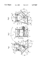
- FIG. 6 is a device consisting of a combination of selector module, metal detector module, and closing module
- FIG. 7 is a device consisting of a combination of selector module, metal detector module, and two closing modules.
- FIGS. 1 to 3 illustrate the selector module 7. It consists of a housing 9, preferably an aluminum housing with an inlet aperture 10 and two outlet apertures 11,12 being opposite to the inlet aperture 10 and being arranged substantially in a trouser leg-like manner.
- the aperture 11 of the two outlet apertures 11,12 is called good side and the aperture 12 is called bad side, i.e. material to be conveyed flowing through the inlet aperture 10 into the selector module 7, e.g. plastic granule, flour, sugar and the like leaves the selector module through the good side if no metal particles are contained therein, and it leaves the selector module through the bad side if it is contaminated with a metal particle, in any case as long as the metal particle is not yet separated.
- Each aperture 10,11,12 has a mounting flange 13,14,15 with mounting holes 16, in the embodiment with four mounting holes 16, respectively.
- the two outlet apertures 11,12 form an asymmetrical wedge 17, in which the shaft 18 of the guiding flap 19 is arranged, as can be seen best in FIG. 3 of the drawings.
- the shaft 18 is unilaterally supported on the selector module housing side 21 facing the actuating mechanism 20 and configured as a carrier on two supports with a carrier arm 22 on which the rectangular guiding flap 19 consisting of sheet metal is mounted.
- the bearing pointing at the interior of the housing is formed as slide bearing 23 and the bearing arranged at the outer housing surface 21 is formed as roller bearing 24.
- the protruding shaft journal 25 is engaged by the actuating mechanism 20 which actuates the guiding flap 19, i.e. it is turned from a position closing the bad side 12 of the device in a position closing the good side 11, and vice versa.
- a pneumatic cylinder or a electromagnet being attached to the housing 9 along with its control unit 27 and connected to the circuit arrangement 60 disposed in the interior of the metal detector module 40 via an electrical plug connection designated with 28 in FIGS. 5, 6 and 7 in order to control the device functions as actuating mechanism 20.
- the pneumatic connection is effected on the fitting 30 of the control valve 27 of the actuating mechanism 20.
- FIG. 3 permits an inside view of the selector module 7 with its cover 31 removed.
- the guiding flap 19 is arranged in the direction of the inlet aperture 10 of the device and abuts in each end position with its free end on a rubber-resilient skirt 32 depending freely into the housing 9.
- two skirts are provided which are attached at the walls by means of strips 33 behind recesses of the housing 9.
- the skirts consist of a soft elastic material such as soft rubber, natural rubber, or plastics, e.g. nitril-butadien-rubber (NBR) and are arranged in spaced relationship with the walls 34,35 of the housing 9, so that the skirts 32 can adapt to the position of the guiding flap 19.
- NBR nitril-butadien-rubber
- the region between the separating plane of the two apertures 11,12 and the shaft 18 is sealed by a sealing strip 36 which is supported in a groove not specifically defined.
- the selector housing wall 28 opposite to the shaft bearings 23,24 is closed by the detachable cover 31 mounted by screws, or by a flap. In case of an opened cover, this aperture functions as mounting or inspection aperture.
- the metal detector module 40 comprises a box-shaped housing 41 with two equally formed housing halves 42,43, and is made of metal, preferably aluminium.
- the housing 41 comprises an inlet aperture 44 and an outlet aperture 45.
- the housing is configured as mounting flange 46,47 with four thread holes 48. With the flanges 46,47, the metal detector module 40 can be connected to the selector module 7 or the closing module 49, as will be described in detail hereinafter.
- annular, inductively acting metal detector 50 with integrated circuit electronics in the part 54 which, with its passage (not shown), is arranged in alignment with the housing apertures 44,45 and mounted to a mounting flange 51 on the upper housing half 42 by means of screws 52 and nuts 53.
- the metal detector 50 is adjusted approximately in the middle of the housing 41 by spacers 55.
- a plastic guide pipe 57 is located in the housing 41 and it extends from the inlet aperture 44 to the outlet aperture 45 and penetrates through the ring aperture of the metal detector 50.
- the material to be examined is directed through the guide pipe 57 and examined for metal particles by the metal detector 50.
- the guide pipe 57 is flush with the mounting flange 46,47 and has a not specifically defined shoulder at each end.
- the guide pipe 57 respectively engages in a mounting ring 58, which is flush inserted in the flange 46,47 and comprises mounting holes 59 for being connected to the housing 41.
- the metal detector 50 as well as the guide pipe 57 may be exchanged for other metal detectors and guide pipes with different passage cross-section dimensions.
- FIG. 4 in the left housing portion, there is a room for the circuit arrangement 60 of the device 37,38,39.
- the individual functions of this control electronics will be described hereinafter.
- the closing module 49,49' is a slide 76 consisting of thin sheet material with a housing 77. Therefore, the slide will not be described in detail.
- the slide is connected to a pneumatic piston-cylinder-unit 61 (pneumatic cylinder) and controlled by the control valve 62.
- the pneumatic connection is effected to the fitting 63.
- the actuating mechanism (pneumatic cylinder 61) and the control of the pneumatic cylinder (control valve 62) may have the same structure as in the case of the selector module 7.
- a connection between the control valve 62 and the circuit arrangement 60 disposed in the metal detector module 40 can be established via an electrical plug device.
- the closing module 49 has mounting flanges 78 with not shown mounting holes, which flanges match with the mounting flanges 13,47 for the connection with the metal detector module 40 or the selector module 7.
- another closing element e.g. a pneumatically actuated squeezing valve, may be used.
- the device 37 illustrated in FIG. 5 for separating metal particles is assembled of the selector module 7 and the metal detector module 40, which is arranged upstream of the selector module and to which a filling funnel 64 is connected.
- the actuating mechanism 20 pneumatic cylinder
- the circuit arrangement 60 disposed in the metal detector module 40, which circuit arrangement is connected to the output of the metal detector 50 via a line 65.
- the metal detector 50 detects the passage of a metal particle when passing the ring aperture and produces an output signal activating the circuit arrangement 60 via the line 65.
- the circuit arrangement 60 produces a control signal which actuates the electrical part of the pneumatic control part 27 via the plug connection 28.
- the actuating mechanism 20 pivots the guiding flap 19 out of its end position, in which it closes the bad side 12, into the other end position, in which it closes the good side 11.
- the circuit arrangement 60 returns the guiding flap back into its initial position.
- the closing module 49' is flanged upstream of the metal detector module 40.
- the control valve 62 is connected to the circuit arrangement 60 in the metal detector module 40.
- the device 38 is connected to a conveyor pipeline 66 and not to a filling funnel.
- the lower connection piece 67 is to represent the machine connection piece of a pressing-injection moulding machine or the counterpart of the conveyor pipeline 66 or the connection piece of a collection container which intermittently stores the material to be conveyed.
- the material flow can be interrupted by the closing module 49' depending on the material take-out of the connection piece 67, so that a pile-up back to the selector module 7 is prevented.
- a sensor 68 e.g. a capacitively acting transducer, which is connected to the circuit arrangement 60 in the metal detector module 40 via the line 69, is arranged at the outlet aperture 11 of the selector module or directly at the connection piece 67. If the level in the connection piece 67 or in the outlet aperture 11 reaches the sensing mark, the sensor produces a control signal which activates the control valve 62 through the circuit arrangement 60 and actuates the pneumatic cylinder 61. Thereby, the material flow is interrupted by the slide 76 until the level in the connection piece 67 has fallen again.
- the device 39 illustrated in FIG. 7 consists of the selector module 7, a closing module 49 connected to the inlet aperture 10 of the selector module 7, a collection connection piece 70 arranged between the first closing module 49 and the metal detector 40, and another closing module 49' connected to the mounting flange 47 upstream of the metal detector module 40.
- the material can be examined "in portions" in case of a corresponding control of the closing modules 49,49'.
- the second closing module 49 is connected to the circuit arrangement 60 in the metal detector module 40 via the plug device 71 and the line 72 as well as the first closing module 49' via the plug device 73 and the line 74.
- a sensor 75 preferably a capacitively acting transducer, which is connected to the circuit arrangement 60 via the line 76, engages with the collection connection piece 70.
- the circuit arrangement controls both closing modules 49,49'. Further, the circuit arrangement controls the selector module 7 depending on the metal particles in the material detected by the metal detector module 40.
- the device 39 of FIG. 7 operates as follows: Initially, both closing modules 49,49' are closed and there is no material to be conveyed in the collection connection piece or the material does not reach the control mark of the sensor 75. Then, the first closing module 49' is opened by the circuit arrangement 60. The collection connection piece 70 is filled up to the sensing mark of the sensor 75. The sensor output signal activates the circuit arrangement which issues a control command to the control valve 62 to close the first closing module 49'.
- the circuit arrangement is activated by a corresponding output signal of the metal detector module 40, which circuit arrangement activates the control valve 27 of the actuating mechanism 20 (pneumatic cylinder) of the selector module 7 via the line 77, whereby the guiding flap 19 closes the good side 11 of the selector module 7 and opens the bad side 12.
- the second closing module 49 is activated and opened by the circuit arrangement. The contents of the collection connection piece 70 are separated through the selector module 7 through the outlet aperture 12 (bad side).
- the transport of its contents proceeds through the outlet aperture 11 (good side) of the selector module 7. Thereafter, the second closing module 49 is closed again.
- the first closing module 49' may be closed by the metal detector module 40 via the circuit arrangement 60 already when the metal detector 50 has detected a metal particle in the material to be conveyed.
Abstract
Description
Claims (23)
Applications Claiming Priority (5)
| Application Number | Priority Date | Filing Date | Title |
|---|---|---|---|
| DE9201767[U] | 1992-02-12 | ||
| DE9201767U DE9201767U1 (en) | 1992-02-12 | 1992-02-12 | |
| DE9201851U DE9201851U1 (en) | 1992-02-14 | 1992-02-14 | |
| DE9201851[U]DEX | 1992-02-14 | ||
| DE4207348A DE4207348A1 (en) | 1992-03-07 | 1992-03-07 | separator for separating metal-particles from flowing material |
Publications (1)
| Publication Number | Publication Date |
|---|---|
| US5377847A true US5377847A (en) | 1995-01-03 |
Family
ID=27203495
Family Applications (1)
| Application Number | Title | Priority Date | Filing Date |
|---|---|---|---|
| US08/016,331 Expired - Fee Related US5377847A (en) | 1992-02-12 | 1993-02-11 | Device for separating metal particles from a flow of material |
Country Status (3)
| Country | Link |
|---|---|
| US (1) | US5377847A (en) |
| EP (1) | EP0555821B1 (en) |
| DE (1) | DE59309618D1 (en) |
Cited By (9)
| Publication number | Priority date | Publication date | Assignee | Title |
|---|---|---|---|---|
| US5887698A (en) * | 1995-11-16 | 1999-03-30 | Sandvik Ab | Method and apparatus for sorting articles received from vertically spaced platforms of a moving transport device |
| US6365858B1 (en) | 1999-06-16 | 2002-04-02 | Pulsotronic Merten Gmbh & Co. Kg | Device for separating metal parts |
| US20090255600A1 (en) * | 2008-04-10 | 2009-10-15 | Lichney John J | Diverter valve and assembly |
| US20130193388A1 (en) * | 2012-01-26 | 2013-08-01 | Echostar Technologies, Llc | Electromagnetic tool for wire routing |
| US20140028309A1 (en) * | 2011-02-25 | 2014-01-30 | Tna Australia Pty Limited | Metal detector |
| DE202016103037U1 (en) | 2016-06-08 | 2016-08-17 | Sartorius Mechatronics C & D Gmbh & Co. Kg | Device for separating off bad fractions from bulk material |
| DE102017125268A1 (en) | 2017-10-27 | 2019-05-02 | Minebea Intec Aachen GmbH & Co. KG | Apparatus for removing contaminants from a pressurized product stream |
| CN110404810A (en) * | 2018-04-26 | 2019-11-05 | 麦斯特罗尼仪器有限责任公司 | For separating the device and method of metallic particles |
| CN112067542A (en) * | 2020-09-16 | 2020-12-11 | 江苏省健尔康医用敷料有限公司 | Disposable medical hand brush inspection device |
Families Citing this family (1)
| Publication number | Priority date | Publication date | Assignee | Title |
|---|---|---|---|---|
| KR20080075231A (en) * | 2003-08-25 | 2008-08-14 | 라이트하우스 원 피티와이 엘티디, 에즈 트러스티 오브 더 라이트하우스 유닛 트러스트 | Sorting apparatus and methods |
Citations (15)
| Publication number | Priority date | Publication date | Assignee | Title |
|---|---|---|---|---|
| US2045769A (en) * | 1928-05-31 | 1936-06-30 | Rca Corp | Electrical control circuit |
| US2444751A (en) * | 1946-02-12 | 1948-07-06 | Western Electric Co | Method and apparatus for sorting magnetic materials according to their residual magnetism |
| DE929046C (en) * | 1950-03-28 | 1955-06-16 | Hoechst Ag | Device for separating metallic foreign bodies from moving grist or the like. |
| DE1809982A1 (en) * | 1968-11-20 | 1970-10-01 | Merten Kg Pulsotronic | Sorting gate operated by a metal detector |
| US3655039A (en) * | 1968-11-20 | 1972-04-11 | Merten Kg Pulsotronic | Separating device for separating metallic matter from non-metallic matter |
| US3776675A (en) * | 1970-09-18 | 1973-12-04 | Olivetti & Co Spa | Injection moulding press with means for separating scrap material from the molded articles |
| DE2944192A1 (en) * | 1979-11-02 | 1981-05-14 | Harro Dipl.-Ing. 8191 Königsdorf Müller | Sorting machine for metal particles - has inductive detector and sorting junction located in vertical chute |
| DE3305268A1 (en) * | 1983-02-16 | 1984-08-16 | Pulsotronic Merten Gmbh & Co Kg, 5270 Gummersbach | Device for separating off metal components |
| US4480753A (en) * | 1979-07-12 | 1984-11-06 | Metal Detectors, Inc. | Metal detector apparatus and method |
| EP0143231A2 (en) * | 1983-11-26 | 1985-06-05 | Pulsotronic Merten GmbH & Co. KG | Apparatus for sorting metallic particles |
| EP0202356A1 (en) * | 1985-05-24 | 1986-11-26 | Motan Plast-Automation AG | Conveyor device |
| EP0266309A2 (en) * | 1986-10-31 | 1988-05-04 | Varicolor Ag | Apparatus for separating foreign parts, in particular metallic particles, from a flowable material |
| DE3823356A1 (en) * | 1988-07-09 | 1990-01-11 | Werner Koch | Apparatus for removing metal parts |
| DE3929709A1 (en) * | 1989-09-07 | 1991-03-14 | Merten Kg Pulsotronic | Metal particles separator for ground or granulate material - uses inductive metal detector controlling operating mechanism for intermediate store |
| DE4017274A1 (en) * | 1990-05-29 | 1991-12-05 | Hamos Elektronik | Magnetic separator for powders, etc. - drops material between HF-energised sensor coils which react to presence of magnetic particles and divert them into separate channel |
Family Cites Families (2)
| Publication number | Priority date | Publication date | Assignee | Title |
|---|---|---|---|---|
| DE2456680C2 (en) * | 1974-11-30 | 1976-12-09 | Merten Kg Pulsotronic | DEVICE FOR SEPARATING METAL PARTS FROM MOVING GOODS, E.G. REGRIND OR GRANULES |
| DE3827024C2 (en) * | 1988-08-05 | 1995-01-19 | S & S Elektronik Geraetebau | Device for detecting and separating contaminants from a stream of plastic or glass material |
-
1993
- 1993-02-10 DE DE59309618T patent/DE59309618D1/en not_active Expired - Fee Related
- 1993-02-10 EP EP93102044A patent/EP0555821B1/en not_active Expired - Lifetime
- 1993-02-11 US US08/016,331 patent/US5377847A/en not_active Expired - Fee Related
Patent Citations (15)
| Publication number | Priority date | Publication date | Assignee | Title |
|---|---|---|---|---|
| US2045769A (en) * | 1928-05-31 | 1936-06-30 | Rca Corp | Electrical control circuit |
| US2444751A (en) * | 1946-02-12 | 1948-07-06 | Western Electric Co | Method and apparatus for sorting magnetic materials according to their residual magnetism |
| DE929046C (en) * | 1950-03-28 | 1955-06-16 | Hoechst Ag | Device for separating metallic foreign bodies from moving grist or the like. |
| DE1809982A1 (en) * | 1968-11-20 | 1970-10-01 | Merten Kg Pulsotronic | Sorting gate operated by a metal detector |
| US3655039A (en) * | 1968-11-20 | 1972-04-11 | Merten Kg Pulsotronic | Separating device for separating metallic matter from non-metallic matter |
| US3776675A (en) * | 1970-09-18 | 1973-12-04 | Olivetti & Co Spa | Injection moulding press with means for separating scrap material from the molded articles |
| US4480753A (en) * | 1979-07-12 | 1984-11-06 | Metal Detectors, Inc. | Metal detector apparatus and method |
| DE2944192A1 (en) * | 1979-11-02 | 1981-05-14 | Harro Dipl.-Ing. 8191 Königsdorf Müller | Sorting machine for metal particles - has inductive detector and sorting junction located in vertical chute |
| DE3305268A1 (en) * | 1983-02-16 | 1984-08-16 | Pulsotronic Merten Gmbh & Co Kg, 5270 Gummersbach | Device for separating off metal components |
| EP0143231A2 (en) * | 1983-11-26 | 1985-06-05 | Pulsotronic Merten GmbH & Co. KG | Apparatus for sorting metallic particles |
| EP0202356A1 (en) * | 1985-05-24 | 1986-11-26 | Motan Plast-Automation AG | Conveyor device |
| EP0266309A2 (en) * | 1986-10-31 | 1988-05-04 | Varicolor Ag | Apparatus for separating foreign parts, in particular metallic particles, from a flowable material |
| DE3823356A1 (en) * | 1988-07-09 | 1990-01-11 | Werner Koch | Apparatus for removing metal parts |
| DE3929709A1 (en) * | 1989-09-07 | 1991-03-14 | Merten Kg Pulsotronic | Metal particles separator for ground or granulate material - uses inductive metal detector controlling operating mechanism for intermediate store |
| DE4017274A1 (en) * | 1990-05-29 | 1991-12-05 | Hamos Elektronik | Magnetic separator for powders, etc. - drops material between HF-energised sensor coils which react to presence of magnetic particles and divert them into separate channel |
Cited By (14)
| Publication number | Priority date | Publication date | Assignee | Title |
|---|---|---|---|---|
| US5887698A (en) * | 1995-11-16 | 1999-03-30 | Sandvik Ab | Method and apparatus for sorting articles received from vertically spaced platforms of a moving transport device |
| US6365858B1 (en) | 1999-06-16 | 2002-04-02 | Pulsotronic Merten Gmbh & Co. Kg | Device for separating metal parts |
| US20090255600A1 (en) * | 2008-04-10 | 2009-10-15 | Lichney John J | Diverter valve and assembly |
| US8051877B2 (en) * | 2008-04-10 | 2011-11-08 | Delphi Technologies, Inc. | Diverter valve and assembly |
| US9599679B2 (en) * | 2011-02-25 | 2017-03-21 | Tna Australia Pty Limited | Metal detector |
| US20140028309A1 (en) * | 2011-02-25 | 2014-01-30 | Tna Australia Pty Limited | Metal detector |
| US9136676B2 (en) * | 2012-01-26 | 2015-09-15 | Echostar Technologies L.L.C. | Electromagnetic tool for wire routing |
| US20130193388A1 (en) * | 2012-01-26 | 2013-08-01 | Echostar Technologies, Llc | Electromagnetic tool for wire routing |
| DE202016103037U1 (en) | 2016-06-08 | 2016-08-17 | Sartorius Mechatronics C & D Gmbh & Co. Kg | Device for separating off bad fractions from bulk material |
| DE102017125268A1 (en) | 2017-10-27 | 2019-05-02 | Minebea Intec Aachen GmbH & Co. KG | Apparatus for removing contaminants from a pressurized product stream |
| DE102017125268B4 (en) | 2017-10-27 | 2022-03-03 | Minebea Intec Aachen GmbH & Co. KG | Device for separating impurities from a pressurized product stream |
| CN110404810A (en) * | 2018-04-26 | 2019-11-05 | 麦斯特罗尼仪器有限责任公司 | For separating the device and method of metallic particles |
| CN110404810B (en) * | 2018-04-26 | 2021-12-28 | 麦斯特罗尼仪器有限责任公司 | Apparatus and method for separating metal particles |
| CN112067542A (en) * | 2020-09-16 | 2020-12-11 | 江苏省健尔康医用敷料有限公司 | Disposable medical hand brush inspection device |
Also Published As
| Publication number | Publication date |
|---|---|
| EP0555821A2 (en) | 1993-08-18 |
| EP0555821A3 (en) | 1993-12-08 |
| DE59309618D1 (en) | 1999-07-08 |
| EP0555821B1 (en) | 1999-06-02 |
Similar Documents
| Publication | Publication Date | Title |
|---|---|---|
| US5377847A (en) | Device for separating metal particles from a flow of material | |
| US3989308A (en) | Weighing apparatus for pneumatic conveying installations | |
| US4545410A (en) | System for transferring dry flowable material | |
| US4753353A (en) | Conveying device | |
| US4200412A (en) | Control for pneumatic conveying system | |
| CA1044732A (en) | Method and apparatus for the pneumatic conveying of bulk material | |
| NO326869B1 (en) | Plants for disposing of several consumers, for example, cells of aluminum melting furnaces with cast iron, for example powdered alumina | |
| JPH0566296B2 (en) | ||
| US7104743B2 (en) | Vacuum receiver with positive dump valve control | |
| US4863040A (en) | Apparatus for separating a contaminated portion of bulk material from a flow of bulk material | |
| CN202687508U (en) | Conveying system for granular solid material and blockage removing device thereof | |
| EP0372402B1 (en) | Particle separator device and apparatus for the pneumatic conveyance of granular materials | |
| ZA916737B (en) | Device for feeding a powdered or granular material into a continuous casting mould | |
| US6365858B1 (en) | Device for separating metal parts | |
| CN108889458B (en) | Explosion-proof centrifuge system | |
| US4763792A (en) | Device for sorting out metal particles | |
| ES8303034A1 (en) | Sausage meat proportioning device. | |
| US3655039A (en) | Separating device for separating metallic matter from non-metallic matter | |
| US3250128A (en) | Sampling device | |
| CN112644904B (en) | Conveying device for use in the plastics field | |
| US3874560A (en) | Pneumatic conveyors | |
| US4394826A (en) | Orifice meter with isolation valve on the carrier | |
| JPS6216893B2 (en) | ||
| US3457789A (en) | Arcuate path diverter with dust closure thereon | |
| US8707806B2 (en) | Sampling and monitoring of particulate suspension material |
Legal Events
| Date | Code | Title | Description |
|---|---|---|---|
| AS | Assignment |
Owner name: PULSOTRONIC MERTEN GMBH & CO. KG, GERMANY Free format text: ASSIGNMENT OF ASSIGNORS INTEREST.;ASSIGNOR:KIND, GUNTRAM;REEL/FRAME:006485/0438 Effective date: 19930317 |
|
| AS | Assignment |
Owner name: PULSOTRONIC MERTEN GMBH & CO. KG, GERMANY Free format text: RECORD TO CORRECT SERIAL NUMBER PREVIOUSLY RECORDED AT REEEL 6485 FRAME 438.;ASSIGNOR:KIND, GUNTRAM;REEL/FRAME:006794/0605 Effective date: 19930317 |
|
| FEPP | Fee payment procedure |
Free format text: PETITION RELATED TO MAINTENANCE FEES FILED (ORIGINAL EVENT CODE: PMFP); ENTITY STATUS OF PATENT OWNER: LARGE ENTITY |
|
| FEPP | Fee payment procedure |
Free format text: PETITION RELATED TO MAINTENANCE FEES GRANTED (ORIGINAL EVENT CODE: PMFG); ENTITY STATUS OF PATENT OWNER: LARGE ENTITY |
|
| FP | Lapsed due to failure to pay maintenance fee |
Effective date: 19990103 |
|
| FPAY | Fee payment |
Year of fee payment: 4 |
|
| SULP | Surcharge for late payment | ||
| PRDP | Patent reinstated due to the acceptance of a late maintenance fee |
Effective date: 19991029 |
|
| FEPP | Fee payment procedure |
Free format text: PAT HOLDER NO LONGER CLAIMS SMALL ENTITY STATUS, ENTITY STATUS SET TO UNDISCOUNTED (ORIGINAL EVENT CODE: STOL); ENTITY STATUS OF PATENT OWNER: LARGE ENTITY |
|
| REFU | Refund |
Free format text: REFUND - PAYMENT OF MAINTENANCE FEE, 8TH YR, SMALL ENTITY (ORIGINAL EVENT CODE: R284); ENTITY STATUS OF PATENT OWNER: LARGE ENTITY |
|
| FEPP | Fee payment procedure |
Free format text: PAYOR NUMBER ASSIGNED (ORIGINAL EVENT CODE: ASPN); ENTITY STATUS OF PATENT OWNER: LARGE ENTITY |
|
| FPAY | Fee payment |
Year of fee payment: 8 |
|
| REMI | Maintenance fee reminder mailed | ||
| LAPS | Lapse for failure to pay maintenance fees | ||
| STCH | Information on status: patent discontinuation |
Free format text: PATENT EXPIRED DUE TO NONPAYMENT OF MAINTENANCE FEES UNDER 37 CFR 1.362 |
|
| FP | Lapsed due to failure to pay maintenance fee |
Effective date: 20070103 |