US5375486A - Surface protective striking tools - Google Patents
Surface protective striking tools Download PDFInfo
- Publication number
- US5375486A US5375486A US08/167,418 US16741893A US5375486A US 5375486 A US5375486 A US 5375486A US 16741893 A US16741893 A US 16741893A US 5375486 A US5375486 A US 5375486A
- Authority
- US
- United States
- Prior art keywords
- core member
- hollow core
- impact
- handle
- outer encasement
- Prior art date
- Legal status (The legal status is an assumption and is not a legal conclusion. Google has not performed a legal analysis and makes no representation as to the accuracy of the status listed.)
- Expired - Lifetime
Links
Images


Classifications
-
- B—PERFORMING OPERATIONS; TRANSPORTING
- B25—HAND TOOLS; PORTABLE POWER-DRIVEN TOOLS; MANIPULATORS
- B25G—HANDLES FOR HAND IMPLEMENTS
- B25G3/00—Attaching handles to the implements
- B25G3/34—Attaching handles to the implements by pressing the handle on the implements; using cement or molten metal, e.g. casting, moulding, by welding or the like
-
- B—PERFORMING OPERATIONS; TRANSPORTING
- B25—HAND TOOLS; PORTABLE POWER-DRIVEN TOOLS; MANIPULATORS
- B25G—HANDLES FOR HAND IMPLEMENTS
- B25G3/00—Attaching handles to the implements
- B25G3/02—Socket, tang, or like fixings
- B25G3/12—Locking and securing devices
-
- B—PERFORMING OPERATIONS; TRANSPORTING
- B29—WORKING OF PLASTICS; WORKING OF SUBSTANCES IN A PLASTIC STATE IN GENERAL
- B29C—SHAPING OR JOINING OF PLASTICS; SHAPING OF MATERIAL IN A PLASTIC STATE, NOT OTHERWISE PROVIDED FOR; AFTER-TREATMENT OF THE SHAPED PRODUCTS, e.g. REPAIRING
- B29C65/00—Joining or sealing of preformed parts, e.g. welding of plastics materials; Apparatus therefor
- B29C65/02—Joining or sealing of preformed parts, e.g. welding of plastics materials; Apparatus therefor by heating, with or without pressure
- B29C65/44—Joining a heated non plastics element to a plastics element
-
- B—PERFORMING OPERATIONS; TRANSPORTING
- B29—WORKING OF PLASTICS; WORKING OF SUBSTANCES IN A PLASTIC STATE IN GENERAL
- B29C—SHAPING OR JOINING OF PLASTICS; SHAPING OF MATERIAL IN A PLASTIC STATE, NOT OTHERWISE PROVIDED FOR; AFTER-TREATMENT OF THE SHAPED PRODUCTS, e.g. REPAIRING
- B29C66/00—General aspects of processes or apparatus for joining preformed parts
- B29C66/80—General aspects of machine operations or constructions and parts thereof
- B29C66/83—General aspects of machine operations or constructions and parts thereof characterised by the movement of the joining or pressing tools
- B29C66/832—Reciprocating joining or pressing tools
- B29C66/8322—Joining or pressing tools reciprocating along one axis
-
- B—PERFORMING OPERATIONS; TRANSPORTING
- B29—WORKING OF PLASTICS; WORKING OF SUBSTANCES IN A PLASTIC STATE IN GENERAL
- B29L—INDEXING SCHEME ASSOCIATED WITH SUBCLASS B29C, RELATING TO PARTICULAR ARTICLES
- B29L2031/00—Other particular articles
- B29L2031/28—Tools, e.g. cutlery
- B29L2031/283—Hand tools
-
- B—PERFORMING OPERATIONS; TRANSPORTING
- B29—WORKING OF PLASTICS; WORKING OF SUBSTANCES IN A PLASTIC STATE IN GENERAL
- B29L—INDEXING SCHEME ASSOCIATED WITH SUBCLASS B29C, RELATING TO PARTICULAR ARTICLES
- B29L2031/00—Other particular articles
- B29L2031/70—Agricultural usage or equipment
-
- Y—GENERAL TAGGING OF NEW TECHNOLOGICAL DEVELOPMENTS; GENERAL TAGGING OF CROSS-SECTIONAL TECHNOLOGIES SPANNING OVER SEVERAL SECTIONS OF THE IPC; TECHNICAL SUBJECTS COVERED BY FORMER USPC CROSS-REFERENCE ART COLLECTIONS [XRACs] AND DIGESTS
- Y10—TECHNICAL SUBJECTS COVERED BY FORMER USPC
- Y10S—TECHNICAL SUBJECTS COVERED BY FORMER USPC CROSS-REFERENCE ART COLLECTIONS [XRACs] AND DIGESTS
- Y10S264/00—Plastic and nonmetallic article shaping or treating: processes
- Y10S264/44—Plastic and nonmetallic article shaping or treating: processes using destructible molds or cores in molding processes
-
- Y—GENERAL TAGGING OF NEW TECHNOLOGICAL DEVELOPMENTS; GENERAL TAGGING OF CROSS-SECTIONAL TECHNOLOGIES SPANNING OVER SEVERAL SECTIONS OF THE IPC; TECHNICAL SUBJECTS COVERED BY FORMER USPC CROSS-REFERENCE ART COLLECTIONS [XRACs] AND DIGESTS
- Y10—TECHNICAL SUBJECTS COVERED BY FORMER USPC
- Y10S—TECHNICAL SUBJECTS COVERED BY FORMER USPC CROSS-REFERENCE ART COLLECTIONS [XRACs] AND DIGESTS
- Y10S264/00—Plastic and nonmetallic article shaping or treating: processes
- Y10S264/76—Processes of uniting two or more parts
Definitions
- This invention relates generally to hand tools and related manufacturing processes. More particularly, the present invention relates to the manufacture of plastic molded surface protective striking tools, such as hammers and mallets, which permits tool components to be assembled together in a simplified manufacturing process, wherein the components are selected to maximize performance of the striking tool while lowering the costs thereof.
- plastic molded surface protective striking tools such as hammers and mallets
- surface protective striking tools such as soft-faced hammers and mallets
- the tool head or impact face is made of a material intended to minimize damage to the work being struck.
- the tool or impact heads have often been made of rawhide, rubber, copper, brass, wood or the like. The particular material chosen for the tool head or impact face has been dependent upon the task to be accomplished.
- surface protective hammers have been devised which utilize a permanent or non-sacrificial handle and head component, and interchangeable and replaceable impact faces which are attachable to a holder provided in the head of the permanent portion of the tool component.
- Such interchangeable and/or replaceable faces are made of a wide range of materials, and particularly out of new engineering plastics, which often exhibit superior working characteristics, i.e., they are tougher, softer, more cut resistant, etc., than traditional tool heads for surface protective striking tools.
- plastic encased tool components are generally known in the art, wherein a skeletal core member is contained within a resilient outer encasement or cladding of molded plastic material or the like.
- the tool component is produced by placing the skeletal core member into a mold cavity which is then filled with a selected thermoplastic molding compound under suitable conditions of heat and pressure.
- the plastic material is permitted to cure, followed by removal of the plastic encased tool component from the mold cavity.
- plastic encased tool components include elongated tool handles, plastic-faced hammers and mallets, etc.
- the skeletal core member In the production of tool components of this general type, the skeletal core member must have sufficient structural integrity to withstand the pressures and temperatures encountered in a typical injection molding environment. That is, the core member must be able to retain its structural size and shape throughout the injection molding process, to prevent production of defective tool components.
- skeletal core members of solid cross-section have been commonly used in the manufacture of plastic encased tool components.
- reduction in the cross-sectional size of a solid core member is ineffective to reduce material costs, since additional molded plastic encasement material is required to form the finished tool component.
- Hollow skeletal core structures have been proposed for use in the manufacture of plastic encased tool components.
- a hollow member beneficially reduces the material cost in the finished tool component without requiring the use of additional molded plastic encasement material.
- a hollow skeletal core reduces the weight of the finished tool component, resulting in a lightweight tool product which can be especially desirable in certain applications.
- core member material has still been required in order to provide the core member with the necessary structural integrity to withstand injection molding processes.
- the striking tool comprises an elongate hollow core member and a pair of impact heads each having an impact face and a skirt extending away from the impact face.
- the skirt of each impact head is fitted over a respective end of the hollow core member, and a molded outer encasement ensheathes the skirts and any exposed portion of the core member therebetween.
- the molded outer encasement binds the impact heads to the hollow core member leaving the impact faces exposed.
- the skirt of each impact head includes surface irregularities to facilitate attachment of the molded outer encasement thereto.
- An access port is provided through both the hollow core member and the molded outer encasement through which a flowable filler material may be added to or removed from the hollow core member.
- a handle is formed integrally with the molded outer encasement, which extends away from the hollow core member generally perpendicularly with respect to a longitudinal axis thereof.
- the access port extends generally centrally through the handle, and is plugged by a reinforcing rod disposed within the handle.
- the reinforcing rod provides stiffness and strength to the handle which might be unavailable if the most economical plastic material were utilized for the molded outer encasement.
- the reinforcing rod includes an irregular outer surface which facilitates securing the reinforcing rod within the handle.
- the present invention also concerns a manufacturing process for making such surface protective striking tools.
- a core member is provided which defines a hollow interior space and an access port opening into the interior space.
- the interior space of the core member is filled with a flow able filler material, and then the access port is closed to retain the filler material within the interior space.
- An impact head having an impact face a skirt extending away therefrom, is placed adjacent to one end of the core member such that said one end of the core member is disposed within the skirt.
- the core member with the filler material therein and the impact head thereon is placed into a mold cavity, and then a plastic material is injected into the mold cavity to form a resilient outer encasement on the core member and the skirt of the impact head.
- the plastic material is allowed to cure to form the striking tool, after which the striking tool is removed from the mold cavity.
- the access port in the core member may then be opened to remove at least a portion of the filler material from the interior space.
- the method of the present invention may further include the step of forming a handle for the striking tool during the molding step.
- the filler material typically comprises solid pellets having a diametric size on the order of 0.005 inch.
- the method may include the step of re-closing the access port after a limited portion of the filler material has been removed from the core member to retain a residual portion of the filler material therein. This provides the resultant striking tool with deadblow or nonrecoil characteristics.
- the step of re-closing the access port includes the steps of inserting a reinforcing rod into the handle so as to be disposed generally centrally therein and extending the length thereof.
- the reinforcing rod is provided with surface irregularities, and is preferably heated prior to inserting it into the handle such that upon insertion of the reinforcing rod, an interior surface of the handle is softened and flows into contact with the surface irregularities of the reinforcing rod to help secure it within the handle.
- a second impact head having a second impact face and a second skirt extending away from the second impact face may be placed adjacent to a second end of the core member prior to the molding step.
- the molding step binds both impact heads to the core member.
- FIG. 1 is a perspective view of a surface protective hammer manufactured in accordance with the present invention
- FIG. 2 is a front elevational view, shown partially in vertical section, illustrating the step of filling an elongate hollow core member with a flowable filler material in accordance with the manufacturing process of the invention
- FIG. 3 is a front elevational view, shown partially in vertical section, illustrating the hollow core member having impact heads placed over each end and placed within an injection mold, wherein a removable core pin extends away from the hollow core member generally perpendicularly relative to its longitudinal axis in alignment with that portion of the mold for forming a handle, wherein the core pin effectively plugs an access port to the hollow core member;
- FIG. 4 is a front elevational view, shown partially in vertical section, illustrating the assembled core member and impact heads of FIG. 3 within the injection mold, with a molded plastic outer encasement formed thereon;
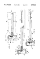
- FIG. 5 is a front elevational view, shown partially in vertical section, similar to FIG. 4, and illustrating removal of the core pin from the handle, and removal of a portion of the filler material from the hollow core member;
- FIG. 6 is a front elevational view similar to FIG. 5, illustrating insertion of a reinforcing rod generally centrally within the handle which, when inserted, closes the access port;
- FIG. 7 is an enlarged, fragmented elevational section taken generally of the area indicated by the number 7 in FIG. 5, illustrating the manner in which the impact heads ensheathe a respective end of the hollow core member, and further illustrating the manner in which the molded plastic outer encasement ensheathes a skirt portion of each impact head and adjacent portions of the hollow core member to secure the impact heads to the core member;
- FIG. 8 is an enlarged fragmented elevational view taken generally of the area indicated by the number 8 in FIG. 6, illustrating surface irregularities provided the reinforcing bar to facilitate securement of the reinforcing bar within the handle;
- FIG. 9 is a perspective view similar to FIG. 1, illustrating another type of surface protective striking tool manufactured in accordance with the present invention.
- FIG. 10 is a front elevational view, shown partially in vertical section, illustrating the elongate hollow core member having impact heads disposed at each end thereof, of the striking tool of FIG. 9, within an injection mold;
- FIG. 11 is a front elevational view, shown partially in vertical section, of the striking tool of FIGS. 9 and 10, illustrating removal of a portion of the filler material from the hollow core member after a molded plastic outer encasement is formed to secure the impact heads to the core member.
- FIGS. 1-8 illustrate the construction and manufacture of a hammer 20 embodying the present invention
- FIGS. 9-11 illustrate a "handleless mallet” 22 likewise embodying the invention.
- Both striking tools 20 and 22 include a lightweight hollow core 24 having a pair of impact heads 26 fitted over the ends of the core, and a molded outer cladding or encasement 28 which ensheathes portions of the impact heads and the hollow core to bind them together.
- the hollow core 24 is substantially filled and structurally backstopped by a flowable filler material 30 to enable the otherwise lightweight core 24 to withstand injection molding pressure and temperature conditions.
- the present invention permits use of a hollow core 24 constructed from a minimum mass of lightweight material, such as a molded or extruded plastic tubular shell, wherein the hollow core may be constructed with inadequate structural strength and rigidity to withstand compressive pressures, etc., applied thereto in the course of injection molding processes to form the outer encasement 28.
- the hollow core 24 defines a generally tubular or cylindrical thin-walled structure with an open interior volume. During injection molding, this interior volume is substantially completely filled by the filler material 30, selected to provide a rigid structural backstop which reinforces and retains the shape integrity of the core 24.
- the filler material 30 is adapted for removal, in whole or in part, from the hollow core 24 of the striking tool 20 or 22 sub sequent to molded formation of the outer encasement 28, thereby providing a lightweight tool component constructed from a comparative minimum of constituent materials.
- the hammer 20 is of the soft-face, deadblow variety and includes, generally, a hammer head 32 and a handle 34 which provides a grip 36, and which extends from the hammer head at a neck portion 38.
- the head 32 includes the lightweight hollow core 24 filled with the flowable filler material 30 and supporting a pair of impact head s 2 6 on opposite ends.
- the molded cladding or encasement 28 also forms the handle 34 during the molding process. Some or all of the filler material 30 is removable from the hollow core 24 through an access port 40 sub sequent to formation of the encasement 28.
- a portion of the filler material 30 remains within the head 32 to provide the hammer 20 with so-called deadblow or nonrecoil characteristics.
- a reinforcing bar 42 is inserted into the handle 34 so as be disposed generally centrally therein and extending the length thereof. The reinforcing bar 42, when so positioned, also closes the access port 40.
- the hollow core member 24 is generally cylindrical and defines an interior chamber 44.
- An aperture 46 is provided in the hollow core 24 which forms a portion of the access port 40, and allows for the introduction of flow able filler material 30.
- each of the impact heads 26 Prior to placing the filled core 24 within an injection mold 48, two impact heads 26 are fitted over the ends of the core.
- Each of the impact heads 26 include an impact face 50 and a skirt 52 which extends away from the impact face.
- the skirt 52 and the impact face 50 cooperatively define an open-sided, generally cylindrical internal chamber into which an end of the core 24 is snugly received.
- the skirt 52 is further provided with a series of beads or rings 54 on the external surface thereof, to facilitate securing the impact heads 26 to the hollow core 24 by the molded plastic encasement 28 following the molding process (FIG. 7).
- the assembled core 24 and impact heads 26 are placed within the injection mold 48, as shown in FIG. 3.
- An elongate core pin 56 is positioned with one end placed either over or within the aperture 46, to extend from the hollow core 24 as a skeletal member for the hammer handle 34.
- plastic encasement material is introduced into the mold 48 under suitable injection molding conditions to form an integral cladding which ensheathes the skirts 52 of the impact heads 26 as well as an intermediate portion of the hollow core 24, and also forms the hammer handle 34 about the core pin 56.
- the encasement material is permitted to cure, thereby defining the plastic molded encasement 28.
- the resultant hammer is separated from the mold 48, and the core pin 56 is withdrawn from the molded plastic handle 34 to open the now formed access port 40, which includes an elongated channel 58 extending generally centrally the length of the handle 34, and the aperture 46 with which the channel 58 is aligned (FIG. 11) .
- Some or all of the filler material 30 can be drained from the hollow core 24 to provide a lightweight hammer head 32.
- a portion (approximately 2/3 to 3/4) of the filler material 30 is retained within the hammer head 32, and the access port 40 is plugged and sealed by means of a fiberglass shaft or reinforcing bar 42 which is press-fit into the channel 58 (FIG. 6) .
- the fiberglass reinforcing bar 42 is provided with external surface irregularities 60 (FIG. 8) and is preferably heated prior to being driven into the channel 58.
- the heated reinforcing bar 42 has a diameter slightly larger than the diameter of the channel 58 such that as it is driven into the thermoplastic encasement 28 defining the handle 34, the thermoplastic material defining the channel 58 is softened and flows into intimate contact around the surface irregularities 60 and then hardens as the heat of the reinforcing bar 42 is dissipated. This serves to securely hold the reinforcing bar 42 in place within the channel 58.
- the reinforcing bar 42 advantageously minimizes any warping or cold-flowing deformation of the handle 34 during use, and significantly strengthens the handle so that the hammer 20 may be used effectively as a striking tool.
- the core pin 56 and the filler material 30 removed from the handle 34 and the hammer head 32 may be reused.
- FIGS. 9-11 illustrate the manufacture of a mallet-like striking tool 22, which is identical in virtually every respect to the hammer 20 described above, with the exception that no handle 34 is provided.
- the same reference numbering system utilized in connection with the hammer 20 will be utilized in the description of the mallet 22 for consistency of identification of similar tool components.
- the mallet 22 includes a lightweight core 24 filled with the flow able filler material 30 and having a pair of impact heads 26 fitted over the opposite ends thereof.
- a plug 62 for the aperture 46 extends therefrom to create a short channel 58 through the plastic molded encasement 28 following the injection molding process.
- the channel 58 and the aperture 46 define the access port 40 through which some or all of the filler material 30 can be drained from the hollow core 24 (FIG. 11).
- the mallet 22 is, essentially, the hammer head 32 manufactured without the handle 34 of the embodiment described above.
- the plastic molded encasement 28 generally ensheathes the skirts 52 and the intermediate portion of the hollow core 24, while leaving the impact faces 50 exposed.
- striking tools manufactured in accordance with the present invention utilize interchangeable components which may be selected to design a custom hand tool for a specific working environment, which hand tool may be made of the most economical materials.
- the impact heads may be selected from a wide variety of materials, for example nylon, polyurethane, and soft vinyls, that provide a wide range of working characteristics, from relatively hard impact face surfaces to very soft.
- the use of adhesives or screw or rivet-type mechanical locking of the impact heads 26 to the hammer head 32 has been eliminated to improve reliable manufacture of the striking tools.
- the deadblow characteristics if desired, can be closely regulated by the amount of flowable filler material 30 retained within the hollow core 24 following the molding process.
- the reinforcing bar 42 provides significant strength enhancement to the handle 34.
- the present invention further provides an improved method for making plastic encased tool components having a lightweight hollow core, wherein the hollow core is structurally backstopped and reinforced by the flowable filler material 30 during injection molding. Subsequent to injection molding of the outer encasement 28, some or all of the filler material 30 can be removed quickly and easily from the core to provide a lightweight and relatively low cost tool component.
Abstract
Description
Claims (10)
Priority Applications (2)
| Application Number | Priority Date | Filing Date | Title |
|---|---|---|---|
| US08/167,418 US5375486A (en) | 1991-06-10 | 1993-12-14 | Surface protective striking tools |
| US08/349,313 US5458840A (en) | 1991-06-10 | 1994-12-05 | Method for making surface protective striking tools |
Applications Claiming Priority (4)
| Application Number | Priority Date | Filing Date | Title |
|---|---|---|---|
| US07/712,690 US5123304A (en) | 1991-06-10 | 1991-06-10 | Process for attaching tool heads to ends of composite handles |
| US75767091A | 1991-11-07 | 1991-11-07 | |
| US08/006,127 US5310230A (en) | 1991-06-10 | 1993-01-19 | Closed back shovel and method of assembly |
| US08/167,418 US5375486A (en) | 1991-06-10 | 1993-12-14 | Surface protective striking tools |
Related Parent Applications (1)
| Application Number | Title | Priority Date | Filing Date |
|---|---|---|---|
| US08/006,127 Continuation-In-Part US5310230A (en) | 1991-06-10 | 1993-01-19 | Closed back shovel and method of assembly |
Related Child Applications (1)
| Application Number | Title | Priority Date | Filing Date |
|---|---|---|---|
| US08/349,313 Division US5458840A (en) | 1991-06-10 | 1994-12-05 | Method for making surface protective striking tools |
Publications (1)
| Publication Number | Publication Date |
|---|---|
| US5375486A true US5375486A (en) | 1994-12-27 |
Family
ID=27485569
Family Applications (2)
| Application Number | Title | Priority Date | Filing Date |
|---|---|---|---|
| US08/167,418 Expired - Lifetime US5375486A (en) | 1991-06-10 | 1993-12-14 | Surface protective striking tools |
| US08/349,313 Expired - Lifetime US5458840A (en) | 1991-06-10 | 1994-12-05 | Method for making surface protective striking tools |
Family Applications After (1)
| Application Number | Title | Priority Date | Filing Date |
|---|---|---|---|
| US08/349,313 Expired - Lifetime US5458840A (en) | 1991-06-10 | 1994-12-05 | Method for making surface protective striking tools |
Country Status (1)
| Country | Link |
|---|---|
| US (2) | US5375486A (en) |
Cited By (26)
| Publication number | Priority date | Publication date | Assignee | Title |
|---|---|---|---|---|
| US5490437A (en) * | 1994-08-25 | 1996-02-13 | Hebert; Paul W. | Hammer |
| US5537896A (en) * | 1993-09-17 | 1996-07-23 | Erwin Halder Kg | Nonmarring hammer |
| US5704259A (en) * | 1995-11-02 | 1998-01-06 | Roush Anatrol, Inc. | Hand operated impact implement having tuned vibration absorber |
| US5804012A (en) * | 1997-01-21 | 1998-09-08 | Carmien; Joseph Allen | Process for manufacturing a filament wound, localized strength tool handle |
| US5916338A (en) * | 1995-07-28 | 1999-06-29 | Hultafors Ab | Hammer with recoil dampening mechanism and counterweight |
| US5935027A (en) * | 1995-12-28 | 1999-08-10 | Roush Anatrol, Inc. | Multi-mode vibration absorbing device for implements |
| WO1999046090A1 (en) * | 1998-03-13 | 1999-09-16 | Joseph Allen Carmien | Nonrecoil impact tool |
| US5996442A (en) * | 1997-08-05 | 1999-12-07 | Carmien; Joseph Allen | Hand tool having interchangeable and replaceable striking heads, and assembly process |
| US6227075B1 (en) | 1999-01-25 | 2001-05-08 | Joseph Allen Carmien | Nonrecoil hammer |
| US6260445B1 (en) | 1999-09-07 | 2001-07-17 | Snap-On Tools Company | Ratcheting composite screwdriver |
| US6311369B1 (en) | 1999-08-20 | 2001-11-06 | Wavex Corporation | Vibration dampening tool handle |
| US6595087B2 (en) | 2001-11-21 | 2003-07-22 | Snap-On Technologies, Inc. | Encapsulated dead blow hammer with improved skeleton |
| US6904829B2 (en) | 2002-09-17 | 2005-06-14 | Anthony Krallman | Deadblow hammer |
| US20060112789A1 (en) * | 2004-11-29 | 2006-06-01 | Hopper Richard L Jr | Dead blow hammer with composite holder |
| US20060257605A1 (en) * | 2005-05-10 | 2006-11-16 | Germain Belanger | Shaft for Tools, A Tool and a Method of Fabrication Thereof |
| US20070256278A1 (en) * | 2006-04-21 | 2007-11-08 | Andre Fortier | Hand tool |
| US7875675B2 (en) | 2005-11-23 | 2011-01-25 | Milgard Manufacturing Incorporated | Resin for composite structures |
| US7901762B2 (en) | 2005-11-23 | 2011-03-08 | Milgard Manufacturing Incorporated | Pultruded component |
| US8101107B2 (en) | 2005-11-23 | 2012-01-24 | Milgard Manufacturing Incorporated | Method for producing pultruded components |
| US8597016B2 (en) | 2005-11-23 | 2013-12-03 | Milgard Manufacturing Incorporated | System for producing pultruded components |
| US20140259695A1 (en) * | 2013-03-15 | 2014-09-18 | Tech Swerve, Llc | Adjustable weight striking device |
| US9044846B1 (en) * | 2012-08-07 | 2015-06-02 | Tech Swerve Llc | Adjustable lightweight camping mallet |
| US9242360B2 (en) | 2012-04-18 | 2016-01-26 | Apex Brands, Inc. | Multiple purpose hand tool |
| US20180001458A1 (en) * | 2014-03-07 | 2018-01-04 | Estwing Manufacturing Company, Inc. | Striking tool with attached striking surface |
| RU2719981C1 (en) * | 2018-09-06 | 2020-04-23 | Фискарс Финлэнд Ой Аб | Hand tool and method of its manufacturing |
| USD1021598S1 (en) | 2022-05-11 | 2024-04-09 | Snap-On Incorporated | Dead blow hammer |
Families Citing this family (6)
| Publication number | Priority date | Publication date | Assignee | Title |
|---|---|---|---|---|
| US5862571A (en) * | 1997-01-10 | 1999-01-26 | Hp Intellectual Corp. | Comfort grip handle and process |
| TWI447002B (en) * | 2013-03-07 | 2014-08-01 | Earthquake hammer structure | |
| SI3245249T1 (en) * | 2015-01-16 | 2020-02-28 | Beaulieu International Group Nv | Covering panel and process of producing covering panels |
| TWI564123B (en) * | 2016-08-03 | 2017-01-01 | 鴻安國際興業有限公司 | Plastic bottle |
| US11091918B2 (en) | 2017-07-13 | 2021-08-17 | Beaulieu International Group Nv | Covering panel and process of producing covering panels |
| US11148271B2 (en) | 2018-11-29 | 2021-10-19 | Snap-On Incorporated | Hammer head with interference fit |
Citations (31)
| Publication number | Priority date | Publication date | Assignee | Title |
|---|---|---|---|---|
| US657422A (en) * | 1898-06-20 | 1900-09-04 | Avery Stamping Company | Shovel. |
| US1374336A (en) * | 1919-12-13 | 1921-04-12 | John S Surbaugh | Handle and blade connection |
| US1755236A (en) * | 1926-07-02 | 1930-04-22 | Wood Shovel And Tool Company | Shovel and shovel handle |
| US2031556A (en) * | 1933-07-31 | 1936-02-18 | Wood Shovel & Tool Company | Shovel |
| US2052616A (en) * | 1932-12-27 | 1936-09-01 | Ncr Co | Key and method of manufacturing the same |
| US2063774A (en) * | 1936-02-03 | 1936-12-08 | Washington Matthew William | Shovel |
| US2238104A (en) * | 1940-01-04 | 1941-04-15 | Union Fork And Hoe Company | Tool handle |
| US2517902A (en) * | 1944-08-31 | 1950-08-08 | George C Luebkeman | Molding process and means |
| US2948649A (en) * | 1956-12-14 | 1960-08-09 | Pancherz Hans Johannes Joachim | Method of manufacturing sections and rods of glass fibre-reinforced plastic |
| US3018140A (en) * | 1959-05-12 | 1962-01-23 | True Temper Corp | Adhesive connection for tool handle |
| US3232355A (en) * | 1963-10-16 | 1966-02-01 | Animal Trap Co America | Garden tool handle |
| US3549189A (en) * | 1968-08-09 | 1970-12-22 | Michael Alosi | Tool handle |
| US3556888A (en) * | 1967-06-23 | 1971-01-19 | Glastrusions | Pultrusion machine and method |
| US3620159A (en) * | 1969-07-24 | 1971-11-16 | James L Gould | Marking hammer |
| US3762453A (en) * | 1971-05-12 | 1973-10-02 | Stanley Works | Hand tool handle |
| GB1376180A (en) * | 1971-12-31 | 1974-12-04 | Spear Jackson Tools Ltd | Spades and shovels |
| US4039012A (en) * | 1976-01-12 | 1977-08-02 | C. E. S., Inc. | Non-rebound hammer |
| US4050727A (en) * | 1976-08-10 | 1977-09-27 | The Union Fork & Hoe Company | Hand-shovel assembly and method of producing it |
| GB2093398A (en) * | 1981-02-17 | 1982-09-02 | Nat Plastics Ltd | Reinforced hollow or tubular articles |
| US4424183A (en) * | 1982-07-06 | 1984-01-03 | Baker International Corporation | Destructible core structure and method for using same |
| US4451073A (en) * | 1982-08-13 | 1984-05-29 | Carmien Joseph A | Flexible core for tool handles |
| WO1984003065A1 (en) * | 1983-02-07 | 1984-08-16 | Electrolux Ab | Method of manufacturing a hollow plastics article |
| FR2555098A1 (en) * | 1983-11-18 | 1985-05-24 | Skf Et Cie Ste Financiere Immo | METHOD FOR REALIZING TAPPING IN A TUBE OR ROD IN A COMPOSITE MATERIAL |
| US4570988A (en) * | 1982-08-13 | 1986-02-18 | Carmien Joseph A | Reinforced tool handle and method of manufacturing same |
| US4605254A (en) * | 1982-08-13 | 1986-08-12 | Carmien Joseph A | Reinforced handle and method of making same |
| US4639029A (en) * | 1985-08-09 | 1987-01-27 | Kolonia Robert A | Tool handle |
| USRE32364E (en) * | 1982-08-13 | 1987-02-24 | Flexible core for tool handles | |
| US4697481A (en) * | 1985-02-21 | 1987-10-06 | Maeda Shell Service Co., Ltd. | Integrally molded hammer with separated head and handle cores |
| US4743481A (en) * | 1986-11-26 | 1988-05-10 | Flex Technologies, Inc. | Molding process for articles having an irregular shaped internal passage |
| US5123304A (en) * | 1991-06-10 | 1992-06-23 | Nupla Corporation | Process for attaching tool heads to ends of composite handles |
| US5262113A (en) * | 1992-08-06 | 1993-11-16 | Carmien Joseph A | Method of making a plastic encased tool component having a lightweight hollow core |
Family Cites Families (3)
| Publication number | Priority date | Publication date | Assignee | Title |
|---|---|---|---|---|
| US3962399A (en) * | 1973-03-12 | 1976-06-08 | The Stanley Works | Method of forming a handle connection for impact tools |
| US4351786A (en) * | 1980-08-25 | 1982-09-28 | Mueller-Perry Co., Inc. | Method for making a stress-relieved composite foamed resin baseball bat or bowling pin |
| US4451041A (en) * | 1982-02-05 | 1984-05-29 | Mizuno Corporation | Golf club head and a method for manufacturing the same |
-
1993
- 1993-12-14 US US08/167,418 patent/US5375486A/en not_active Expired - Lifetime
-
1994
- 1994-12-05 US US08/349,313 patent/US5458840A/en not_active Expired - Lifetime
Patent Citations (31)
| Publication number | Priority date | Publication date | Assignee | Title |
|---|---|---|---|---|
| US657422A (en) * | 1898-06-20 | 1900-09-04 | Avery Stamping Company | Shovel. |
| US1374336A (en) * | 1919-12-13 | 1921-04-12 | John S Surbaugh | Handle and blade connection |
| US1755236A (en) * | 1926-07-02 | 1930-04-22 | Wood Shovel And Tool Company | Shovel and shovel handle |
| US2052616A (en) * | 1932-12-27 | 1936-09-01 | Ncr Co | Key and method of manufacturing the same |
| US2031556A (en) * | 1933-07-31 | 1936-02-18 | Wood Shovel & Tool Company | Shovel |
| US2063774A (en) * | 1936-02-03 | 1936-12-08 | Washington Matthew William | Shovel |
| US2238104A (en) * | 1940-01-04 | 1941-04-15 | Union Fork And Hoe Company | Tool handle |
| US2517902A (en) * | 1944-08-31 | 1950-08-08 | George C Luebkeman | Molding process and means |
| US2948649A (en) * | 1956-12-14 | 1960-08-09 | Pancherz Hans Johannes Joachim | Method of manufacturing sections and rods of glass fibre-reinforced plastic |
| US3018140A (en) * | 1959-05-12 | 1962-01-23 | True Temper Corp | Adhesive connection for tool handle |
| US3232355A (en) * | 1963-10-16 | 1966-02-01 | Animal Trap Co America | Garden tool handle |
| US3556888A (en) * | 1967-06-23 | 1971-01-19 | Glastrusions | Pultrusion machine and method |
| US3549189A (en) * | 1968-08-09 | 1970-12-22 | Michael Alosi | Tool handle |
| US3620159A (en) * | 1969-07-24 | 1971-11-16 | James L Gould | Marking hammer |
| US3762453A (en) * | 1971-05-12 | 1973-10-02 | Stanley Works | Hand tool handle |
| GB1376180A (en) * | 1971-12-31 | 1974-12-04 | Spear Jackson Tools Ltd | Spades and shovels |
| US4039012A (en) * | 1976-01-12 | 1977-08-02 | C. E. S., Inc. | Non-rebound hammer |
| US4050727A (en) * | 1976-08-10 | 1977-09-27 | The Union Fork & Hoe Company | Hand-shovel assembly and method of producing it |
| GB2093398A (en) * | 1981-02-17 | 1982-09-02 | Nat Plastics Ltd | Reinforced hollow or tubular articles |
| US4424183A (en) * | 1982-07-06 | 1984-01-03 | Baker International Corporation | Destructible core structure and method for using same |
| US4570988A (en) * | 1982-08-13 | 1986-02-18 | Carmien Joseph A | Reinforced tool handle and method of manufacturing same |
| US4451073A (en) * | 1982-08-13 | 1984-05-29 | Carmien Joseph A | Flexible core for tool handles |
| US4605254A (en) * | 1982-08-13 | 1986-08-12 | Carmien Joseph A | Reinforced handle and method of making same |
| USRE32364E (en) * | 1982-08-13 | 1987-02-24 | Flexible core for tool handles | |
| WO1984003065A1 (en) * | 1983-02-07 | 1984-08-16 | Electrolux Ab | Method of manufacturing a hollow plastics article |
| FR2555098A1 (en) * | 1983-11-18 | 1985-05-24 | Skf Et Cie Ste Financiere Immo | METHOD FOR REALIZING TAPPING IN A TUBE OR ROD IN A COMPOSITE MATERIAL |
| US4697481A (en) * | 1985-02-21 | 1987-10-06 | Maeda Shell Service Co., Ltd. | Integrally molded hammer with separated head and handle cores |
| US4639029A (en) * | 1985-08-09 | 1987-01-27 | Kolonia Robert A | Tool handle |
| US4743481A (en) * | 1986-11-26 | 1988-05-10 | Flex Technologies, Inc. | Molding process for articles having an irregular shaped internal passage |
| US5123304A (en) * | 1991-06-10 | 1992-06-23 | Nupla Corporation | Process for attaching tool heads to ends of composite handles |
| US5262113A (en) * | 1992-08-06 | 1993-11-16 | Carmien Joseph A | Method of making a plastic encased tool component having a lightweight hollow core |
Cited By (36)
| Publication number | Priority date | Publication date | Assignee | Title |
|---|---|---|---|---|
| US5537896A (en) * | 1993-09-17 | 1996-07-23 | Erwin Halder Kg | Nonmarring hammer |
| US5490437A (en) * | 1994-08-25 | 1996-02-13 | Hebert; Paul W. | Hammer |
| US5916338A (en) * | 1995-07-28 | 1999-06-29 | Hultafors Ab | Hammer with recoil dampening mechanism and counterweight |
| US5704259A (en) * | 1995-11-02 | 1998-01-06 | Roush Anatrol, Inc. | Hand operated impact implement having tuned vibration absorber |
| US5935027A (en) * | 1995-12-28 | 1999-08-10 | Roush Anatrol, Inc. | Multi-mode vibration absorbing device for implements |
| US5804012A (en) * | 1997-01-21 | 1998-09-08 | Carmien; Joseph Allen | Process for manufacturing a filament wound, localized strength tool handle |
| US5996442A (en) * | 1997-08-05 | 1999-12-07 | Carmien; Joseph Allen | Hand tool having interchangeable and replaceable striking heads, and assembly process |
| WO1999046090A1 (en) * | 1998-03-13 | 1999-09-16 | Joseph Allen Carmien | Nonrecoil impact tool |
| US6052885A (en) * | 1998-03-13 | 2000-04-25 | Carmien; Joseph Allen | Method of making a nonrecoil impact tool |
| US6234048B1 (en) | 1999-01-25 | 2001-05-22 | Joseph Allen Carmien | Nonrecoil hammer |
| US6227075B1 (en) | 1999-01-25 | 2001-05-08 | Joseph Allen Carmien | Nonrecoil hammer |
| CN1329163C (en) * | 1999-08-20 | 2007-08-01 | 韦弗克斯公司 | Vibration dampening tool handle |
| US6311369B1 (en) | 1999-08-20 | 2001-11-06 | Wavex Corporation | Vibration dampening tool handle |
| US6260445B1 (en) | 1999-09-07 | 2001-07-17 | Snap-On Tools Company | Ratcheting composite screwdriver |
| US6595087B2 (en) | 2001-11-21 | 2003-07-22 | Snap-On Technologies, Inc. | Encapsulated dead blow hammer with improved skeleton |
| US6904829B2 (en) | 2002-09-17 | 2005-06-14 | Anthony Krallman | Deadblow hammer |
| US20050193868A1 (en) * | 2002-09-17 | 2005-09-08 | Anthony Krallman | Deadblow hammer |
| US7134363B2 (en) | 2002-09-17 | 2006-11-14 | Anthony Krallman | Deadblow hammer |
| US20070051207A1 (en) * | 2002-09-17 | 2007-03-08 | Anthony Krallman | Deadblow hammer |
| US20060112789A1 (en) * | 2004-11-29 | 2006-06-01 | Hopper Richard L Jr | Dead blow hammer with composite holder |
| US7168338B2 (en) | 2004-11-29 | 2007-01-30 | Snap-On Incorporated | Dead blow hammer with composite holder |
| US20060257605A1 (en) * | 2005-05-10 | 2006-11-16 | Germain Belanger | Shaft for Tools, A Tool and a Method of Fabrication Thereof |
| US7875675B2 (en) | 2005-11-23 | 2011-01-25 | Milgard Manufacturing Incorporated | Resin for composite structures |
| US7901762B2 (en) | 2005-11-23 | 2011-03-08 | Milgard Manufacturing Incorporated | Pultruded component |
| US8101107B2 (en) | 2005-11-23 | 2012-01-24 | Milgard Manufacturing Incorporated | Method for producing pultruded components |
| US8519050B2 (en) | 2005-11-23 | 2013-08-27 | Milgard Manufacturing Incorporated | Resin for composite structures |
| US8597016B2 (en) | 2005-11-23 | 2013-12-03 | Milgard Manufacturing Incorporated | System for producing pultruded components |
| US20070256278A1 (en) * | 2006-04-21 | 2007-11-08 | Andre Fortier | Hand tool |
| US9242360B2 (en) | 2012-04-18 | 2016-01-26 | Apex Brands, Inc. | Multiple purpose hand tool |
| US9044846B1 (en) * | 2012-08-07 | 2015-06-02 | Tech Swerve Llc | Adjustable lightweight camping mallet |
| US20140259695A1 (en) * | 2013-03-15 | 2014-09-18 | Tech Swerve, Llc | Adjustable weight striking device |
| US11097438B2 (en) * | 2013-03-15 | 2021-08-24 | Tech Swerve, Llc | Adjustable weight striking device |
| US20180001458A1 (en) * | 2014-03-07 | 2018-01-04 | Estwing Manufacturing Company, Inc. | Striking tool with attached striking surface |
| US10710228B2 (en) * | 2014-03-07 | 2020-07-14 | Estwing Manufacturing Company, Inc. | Striking tool with attached striking surface |
| RU2719981C1 (en) * | 2018-09-06 | 2020-04-23 | Фискарс Финлэнд Ой Аб | Hand tool and method of its manufacturing |
| USD1021598S1 (en) | 2022-05-11 | 2024-04-09 | Snap-On Incorporated | Dead blow hammer |
Also Published As
| Publication number | Publication date |
|---|---|
| US5458840A (en) | 1995-10-17 |
Similar Documents
| Publication | Publication Date | Title |
|---|---|---|
| US5375486A (en) | Surface protective striking tools | |
| US4451042A (en) | Golf club head of carbon fiber reinforced plastic | |
| US4334563A (en) | Swingable impact tool | |
| US4449707A (en) | Golf club head of carbon fiber reinforced plastic | |
| US6530098B1 (en) | Multiple tool device | |
| US4039012A (en) | Non-rebound hammer | |
| US4451041A (en) | Golf club head and a method for manufacturing the same | |
| US7134363B2 (en) | Deadblow hammer | |
| US4287640A (en) | Tool handle and method of making same | |
| EP0517709B1 (en) | Tool handle and method of attaching a handle to a percussive tool head | |
| US4119313A (en) | Games racquets | |
| US3844321A (en) | Unitarily cast hammer | |
| US3762453A (en) | Hand tool handle | |
| US5034082A (en) | Method of constructing a tennis racket | |
| JP2620967B2 (en) | Golf club head manufacturing method | |
| US20090089972A1 (en) | Flexible grip and method of making same | |
| US20040084815A1 (en) | One-piece shaft construction and a method of construction using bladder molding | |
| AU2770700A (en) | Golf club shaft | |
| US6962098B2 (en) | Undermolded structures and method of making same | |
| US5273280A (en) | Golf club construction | |
| US4344901A (en) | Method of making tool handle | |
| CA3180082A1 (en) | Axe and a method for manufacturing an axe | |
| EP2654491B1 (en) | Silicone broom and a manufacturing method of silicone broom | |
| NO145783B (en) | SLAGVERKTOEY. | |
| US20050252345A1 (en) | Non-recoil striking tool and process for making same |
Legal Events
| Date | Code | Title | Description |
|---|---|---|---|
| STCF | Information on status: patent grant |
Free format text: PATENTED CASE |
|
| FPAY | Fee payment |
Year of fee payment: 4 |
|
| FPAY | Fee payment |
Year of fee payment: 8 |
|
| AS | Assignment |
Owner name: MARWIT CAPITAL COMPANY, L.P., CALIFORNIA Free format text: SECURITY AGREEMENT;ASSIGNOR:NUPLA ACQUISITION CORPORATION;REEL/FRAME:013589/0481 Effective date: 20021209 Owner name: NUPLA ACQUISITION CORPORATION, CALIFORNIA Free format text: ASSIGNMENT OF ASSIGNORS INTEREST;ASSIGNOR:CARMIEN FAMILY 1991 TRUST;REEL/FRAME:013589/0489 Effective date: 20021209 |
|
| AS | Assignment |
Owner name: NUPLA CORPORATION, CALIFORNIA Free format text: ASSIGNMENT OF ASSIGNORS INTEREST;ASSIGNOR:NUPLA ACQUISITION CORPORATION;REEL/FRAME:015139/0494 Effective date: 20040323 |
|
| FPAY | Fee payment |
Year of fee payment: 12 |
|
| AS | Assignment |
Owner name: NUPLA CORPORATION, CALIFORNIA Free format text: RELEASE BY SECURED PARTY;ASSIGNOR:MARWIT CAPITAL COMPANY, L.P.;REEL/FRAME:019781/0763 Effective date: 20070904 Owner name: PATRIOT CAPITAL FUNDING, INC., AS AGENT WITH RESPE Free format text: SECURITY AGREEMENT;ASSIGNOR:NUPLA CORPORATION;REEL/FRAME:019781/0858 Effective date: 20070904 |
|
| AS | Assignment |
Owner name: PATRIOT CAPITAL FUNDING, INC., AS AGENT WITH RESPE Free format text: SECURITY AGREEMENT;ASSIGNOR:NUPLA CORPORATION;REEL/FRAME:019795/0145 Effective date: 20070904 |
|
| AS | Assignment |
Owner name: Q.E.P. CO., INC., FLORIDA Free format text: RELEASE BY SECURED PARTY;ASSIGNOR:PROSPECT CAPITAL CORPORATION, AS AGENT WITH RESPECT TO CERTAIN SENIOR SECURED LOANS (AS SUCCESSOR BY MERGER TO PATRIOT CAPITAL FUNDING, INC.);REEL/FRAME:028439/0948 Effective date: 20120615 |
|
| AS | Assignment |
Owner name: Q.E.P. CO., INC., FLORIDA Free format text: RELEASE BY SECURED PARTY;ASSIGNOR:PROSPECT CAPITAL CORPORATION, AS AGENT WITH RESPECT TO CERTAIN SUBORDINATED SECURED LOANS (AS SUCCESSOR BY MERGER TO PATRIOT CAPITAL FUNDING, INC.);REEL/FRAME:028449/0126 Effective date: 20120615 |