US5368115A - Undercarriage assembly for a vehicle - Google Patents
Undercarriage assembly for a vehicle Download PDFInfo
- Publication number
- US5368115A US5368115A US08/161,842 US16184293A US5368115A US 5368115 A US5368115 A US 5368115A US 16184293 A US16184293 A US 16184293A US 5368115 A US5368115 A US 5368115A
- Authority
- US
- United States
- Prior art keywords
- roller frame
- assembly
- assemblies
- vehicle
- spindle
- Prior art date
- Legal status (The legal status is an assumption and is not a legal conclusion. Google has not performed a legal analysis and makes no representation as to the accuracy of the status listed.)
- Expired - Lifetime
Links
Images


Classifications
-
- B—PERFORMING OPERATIONS; TRANSPORTING
- B62—LAND VEHICLES FOR TRAVELLING OTHERWISE THAN ON RAILS
- B62D—MOTOR VEHICLES; TRAILERS
- B62D55/00—Endless track vehicles
- B62D55/08—Endless track units; Parts thereof
- B62D55/084—Endless-track units or carriages mounted separably, adjustably or extensibly on vehicles, e.g. portable track units
-
- B—PERFORMING OPERATIONS; TRANSPORTING
- B62—LAND VEHICLES FOR TRAVELLING OTHERWISE THAN ON RAILS
- B62D—MOTOR VEHICLES; TRAILERS
- B62D55/00—Endless track vehicles
- B62D55/08—Endless track units; Parts thereof
-
- B—PERFORMING OPERATIONS; TRANSPORTING
- B62—LAND VEHICLES FOR TRAVELLING OTHERWISE THAN ON RAILS
- B62D—MOTOR VEHICLES; TRAILERS
- B62D55/00—Endless track vehicles
- B62D55/08—Endless track units; Parts thereof
- B62D55/30—Track-tensioning means
- B62D55/305—Track-tensioning means acting on pivotably mounted idlers
-
- Y—GENERAL TAGGING OF NEW TECHNOLOGICAL DEVELOPMENTS; GENERAL TAGGING OF CROSS-SECTIONAL TECHNOLOGIES SPANNING OVER SEVERAL SECTIONS OF THE IPC; TECHNICAL SUBJECTS COVERED BY FORMER USPC CROSS-REFERENCE ART COLLECTIONS [XRACs] AND DIGESTS
- Y10—TECHNICAL SUBJECTS COVERED BY FORMER USPC
- Y10S—TECHNICAL SUBJECTS COVERED BY FORMER USPC CROSS-REFERENCE ART COLLECTIONS [XRACs] AND DIGESTS
- Y10S180/00—Motor vehicles
- Y10S180/906—Adjustable axles
Definitions
- This invention relates generally to an undercarriage assembly for a work vehicle and more particularly to an undercarriage assembly which includes first and second roller frame portions, a plurality of guide rollers, first and second idler wheels, an endless elastomeric belt, and first and second self-contained hydraulic tensioning assemblies connected between respective first and second idler wheels and first and second roller frame portions.
- Construction, earthmoving, and agricultural type work vehicles are often equipped with endless self-laying track chain assemblies for support and propulsion of the vehicle.
- Such prior art track type vehicles, utilizing metal track chain assemblies are generally low speed, noisy vehicles and work in environments which do not require any adjustment to the track gauge.
- work vehicles having endless elastomeric track belts have been utilized to perform work tasks previously accomplished by metal track equipped vehicles.
- the vehicles having elastomeric track belts have many advantages over metal track vehicles and also over wheel type work vehicles. Some of these advantages include less weight and maintenance, lower soil compaction, lower noise levels, and the ability to travel on improved roadways.
- the present invention is directed toward overcoming one or more of the problems as set forth above.
- an undercarriage assembly for a vehicle having a main frame and first and second drive axles includes first and second roller frame assemblies connected respectively to the drive axles, a support beam connected to the vehicle main frame and to each roller frame assembly, first and second self-aligning idler wheel assemblies, and first and second endless track assemblies and the idler wheel assemblies.
- the undercarriage assembly further includes first and second track tensioning mechanisms, a first self-aligning mechanism connecting each track tension mechanism to one of the idler wheel assemblies, and a second self-aligning mechanism connecting each track roller frame assembly to one of the idler wheel assemblies.
- Prior art belted track vehicles generally incorporate endless belts having guide blocks on the inner side of the belt which guide and center the belt as the belt rotates around the drive wheel, guide rollers, and idler wheel.
- Each of the wheel and roller assemblies generally include a pair of spaced wheels with the space accommodating the guide blocks. If the belt does not run straight, the guide blocks contact the wheels and rollers, which generated excessive heat and accelerated wear.
- the prior art belted track vehicles also utilize hydraulic cylinders to tension the belts and provide recoil functions.
- the tensioning cylinders which are supported by the track roller frames, are connected by hydraulic lines to the vehicle hydraulic system. These lines are subject to wear and rupture which causes contamination of the entire vehicle hydraulic system.
- the subject invention provides an undercarriage assembly having self-aligning idler wheel assemblies which adjust to properly center the drive belt.
- the subject invention further provides a self-contained hydraulic tensioning ram having no hydraulic connecting lines between the ram and the vehicle.
- FIG. 1 is a diagrammatic side elevational view of a vehicle incorporating the subject invention
- FIG. 2 is a diagrammatic cross-sectional view taken generally along the lines 2--2 of FIG. 1;
- FIG. 3 is a diagrammatic side elevational view, partly in section, of a self-aligning mechanism of the present invention
- FIG. 4 is a diagrammatic cross-sectional view taken generally along the lines 4--4 of FIG. 3;
- FIG. 5 is a diagrammatic front elevational view, partly in section, of a portion of the support beam, the vehicle frame, and the undercarriage roller frame;
- FIG. 6 is a diagrammatic side elevational view, partly in section, taken generally along the lines 6--6 of FIG. 5;
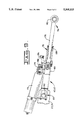
- FIG. 7 is a diagrammatic top plan view, partly in section, of a rear drive wheel, a drive axle, a portion of a roller frame assembly, and the connection between the roller frame assembly and the drive axle;
- FIG. 9 is a diagrammatic side elevational view of the self-contained hydraulic ram of the subject invention.
- a belted track vehicle 10 has a main frame 12, an engine 14, and first and second drive axles 16, 18 which are powered by the engine 14.
- An undercarriage assembly 20 for the vehicle includes first and second roller frame assemblies 22, 24, a support beam 26, first and second self-aligning idler wheel assemblies 28, 30, first and second drive wheels 32, 34, and first and second endless track assemblies 36, 38 encircling respectively the first and second drive wheels 32, 34, the first and second roller frame assemblies 22, 24, and the first and second idler wheel assemblies 28, 30.
- Each of the track assemblies 36, 38 includes an endless elastomeric belt 39 which supports and propels the vehicle.
- the belt 39 has a plurality of inwardly facing guide blocks 41.
- the undercarriage assembly 20 further includes first and second self-contained hydraulic belt tensioning mechanisms 40, 42. It is to be understood that most of the components of the undercarriage assembly 20 on the left hand side of the vehicle 10, as shown in FIG. 1, are duplicated and are substantially similar to those components on the right hand side.
- Each of the roller frame assemblies 22, 24 has first and second end portions 44, 46 and a middle portion 48, with the second end portions 46 being releasably connected to a respective first and second drive axle 16, 18.
- the support beam 26 has first and second end portions 50, 52 and a middle portion 54 which is releasably connected to the vehicle main frame 12.
- the first and second end portions 50, 52 are releasably connected to the middle portion 48 of a respective first and second roller frame assembly 22, 24.
- Each of the idler wheel assemblies 28, 30 has a spindle 56 and first and second spaced wheels 58, 60 rotatably supported on the spindle 56.
- Each spindle 56 includes first and second spaced apart shaft portions 61, 63, a middle portion 65, and first and second plates 67, 69 rotatably connected to respective first and second shaft portions 61, 63.
- the wheels 58, 60 are connected to respective first and second plates 67, 69.
- Each spindle 56 also has first and second radially extending flange or ear portions 62, 64, with the first ear portion 62 having first and second spaced flanges 66, 68 which define a space 70 therebetween.
- a first self-aligning mechanism 72 including a spherical bearing assembly 74, is positioned between the flanges 66, 68 and within the space 70.
- Each of the track tensioning mechanisms 40, 42 includes an hydraulic ram assembly 76 having a first end portion 78 connected to a respective first spindle ear portion 62.
- a second end portion 80 of each ram assembly 76 is connected to a respective roller frame assembly 22, 24.
- the first self-aligning mechanism 72 serves to connect the first end portion 44 of each track tensioning mechanism 40, 42 to the first ear portion 62 of each spindle 56 by way of a retaining pin 82.
- the retaining pin 82 has a radially extending connecting portion 84 which is connected to the first flange or ear portion 62.
- the second ear portions 64 include third and fourth spaced flanges 86, 88, and a second self-aligning mechanism 90 is positioned between and connected to these flanges 86, 88.
- a means 92 for pivotally connecting the second self-aligning mechanism 90 to the roller frame 22 includes a lever member 93 and a cap member 95.
- the first end portion 44 of each roller frame assembly 22, 24 has a forwardly extending nose portion 92 and the second self-aligning mechanism 90 connects the nose portion 92 to the second flange, or ear, portion 64 of each spindle 56.
- the second self-aligning mechanism 90 serves to releasably connect each spindle 56 to the first end portion 44 of each roller frame assembly 22, 24.
- the second self-aligning mechanism 90 includes a universal type apparatus 94 having a block portion 96 having first and second connecting portions 98, 100.
- the first connecting portion 98 includes first and second connecting pins 102, 104 and the second connecting portion 100 includes a third connecting pin 106.
- the third connecting pin 106 is positioned at an angle which is substantially normal to the first and second pins 102, 104.
- the third and fourth spaced flanges 86, 88 are adapted to be pivotally connected to said third connecting pin 106.
- the universal type apparatus 94 includes the lever member 93 and the cap member 95, with the block portion 96 forming a portion of the lever member 93.
- the cap member 95 has a mounting portion 108 and a pin receiving portion 110, with the mounting portion 108 being connected to the roller frame assembly 22 by a plurality of threaded fasteners 112.
- the pin receiving portion 110 is adapted to receive the second connecting pin 104 of the universal type apparatus 94.
- the lever member 93 includes a bifurcated yoke portion 114 at one end and the block portion 96 at the opposite end.
- the yoke portion 114 is adapted to surround the mounting portion 108 of the cap member 95.
- the block portion 96 has a bore 116 extending therethrough at an angle which is substantially normal to the first and second connecting pins 102, 104.
- the third connecting pin 106 is positioned within the bore 116 and, as previously noted, pivotally connects the third and fourth flanges 86, 88 to the block portion 96.
- a securing means 118 such as a circumferential groove 120 in the pin 106 and a threaded fastener 121 extending through the block portion 96, secures the pin 106 within the bore 116.
- the forwardly extending nose portion 92 is adapted to receive the first connecting pin 102, and in combination with the cap member 95 and the second connecting pin 104, pivotally connects the idler wheel assembly 28 to the roller frame assembly 22.
- First and second threaded fasteners 128, 130, and corresponding first and second threaded holes 132, 134 in the yoke portion 114 of the lever member 93 provide a means for moving the yoke portion 114 laterally relative to the cap member 95.
- the threaded fasteners 128, 130 are adapted to engage an extension 136 of the roller frame assembly 22.
- First and second lock nuts 138, 140 engage the respective first and second threaded fasteners 128, 130 and the yoke portion 114 to provide a means for locking the yoke portion 114 at a plurality of positions.
- a means 142 is provided for supporting the first roller frame assemble 22 by the second roller frame assembly 24 when the first roller frame assembly 22 is disconnected from the first drive axle 16 and from the support beam 26.
- the means 142 includes first and second heavy walled tube sections 144, 146 connected, as by welding, to the first roller frame assembly 22, and third and fourth heavy walled tube sections 148, 150 connected to the second roller frame assembly 24.
- the supporting means 142 further includes a first bar 152 extending through the first and third tubes 144, 148 and a second bar 154 extending through the second and fourth tubes 146, 150.
- the same supporting means 142 is used to support the second roller frame assembly 24 by the first roller frame 22 when the second roller frame assembly 24 is disconnected from the second drive axle 18 and from the support beam 26.
- the first and third tube sections 144, 148 are substantially axially aligned.
- the first and second bars 152, 154 extend completely across the vehicle 10 and beneath the main frame 12 to engage and extend through the respective tube sections 144, 148 and 146, 150.
- a means 156 is provided for positioning each of the roller frame assemblies 22, 24 at a plurality of locations laterally spaced from the main frame 12.
- the positioning means 156 includes a plurality of first and second spacers 158, 160.
- the first spacers 158 are adapted to be connected between the second end portions 46 of the roller frame assemblies 22, 24, and the drive axles 16, 18.
- the second spacers 160 are adapted to be connected between the middle portions 48 of the roller frame assemblies 22, 24 and the first and second ends 50, 52 of the support beam 26.
- the spacers 158, 160 provide adjustment of the gage setting of the endless track assemblies 36, 38. Although only one set of spacers 158, 160 is illustrated, it is understood that a plurality of different sizes of spacers can be used for varying the gage settings.
- the supporting means 142 are utilized during the changing of the track gage.
- First and second brackets 162, 164 releasably connect the middle portion 54 of the support beam 26 to the main frame 12 of the vehicle 10.
- the brackets 162, 164 are connected to the main frame 12 by a plurality of first threaded fasteners 166 and to the support beam 26 by a plurality of second threaded fasteners 168.
- a plurality of resilient spaces 170 are positioned between the support beam and the brackets 162, 164, and between a clamp plate 172 and the brackets 162, 164 and are compressed by the second threaded fasteners 168. This provides a resilient mounting of the support beam 26.
- each of the track tensioning mechanisms 40, 42 includes the hydraulic ram assembly 76, an accumulator 174, and a manifold block 176.
- the hydraulic ram assembly 76 includes a rod 178 and a pressure chamber 180.
- the accumulator 174 is in direct fluid communication with the pressure chamber 180 through the manifold block 176.
- the rod 178 includes an eye portion 182 which connects with the first flange portion 62 of the idler assemblies 28, 30.
- the manifold block 176 includes a fill and shut-off valve assembly 184 and a bleed valve 186.
- the pressure chamber 180 and accumulator 174 are initially pressurized from a remote hydraulic source, such as the hydraulic implement circuit of the vehicle 10.
- the track tensioning mechanisms 40, 42 are substantially self sustaining, since they are void of any hydraulic connections to the vehicle 10.
- One of more pressure seals 188 which seal on the polished surface of the rod 178, prevent any appreciable fluid leakage from the pressure chamber 180. If the pressure chamber ever needs recharging, the fill and shut-off valve 184 is used.
- the second end portions 80 of each ram assembly 76 is connected to the roller frame assemblies 22, 24 by mounting pins 192.
- the subject invention is particularly useful on agricultural type work vehicles, and more specifically on work vehicles which are supported and propelled by endless elastomeric track belts. It is advantageous that such vehicles have good traction, low ground pressure, low soil compaction, relatively high ground clearance, and have variable gage capabilities. The variable gage is especially useful for operating the vehicle in agricultural fields having different row crop spacings.
- the vehicle 10 is supported and propelled by an undercarriage assembly 20 which includes first and second roller frame assemblies 22, 24, first and second idler assemblies 28, 30, first and second drive wheels 32, 34, and first and second endless track assemblies 36, 38.
- a self-contained hydraulic belt tensioning mechanism 40, 42 is connected at one end to the roller frame assembly 22, 24 by a pin 192, and is connected at the opposite end to the first self-aligning mechanism 72 by the eye portion 182.
- the second self-aligning mechanism 90 connects each idler assembly 28, 30 to the roller frame assemblies 22, 24 and provides pivoting of the idler assemblies 28, 30 about the third pin 106 and against the force of the tensioning mechanism 40, 42.
- the first and second self-aligning mechanism 72, 90 provide for self alignment of the belt 39 on the idler assemblies 28, 30 and prevent extended contact between the guide blocks 41 and the wheels 58, 60.
- the gage of the track belts is changed by disconnecting the first end portion 44 and the middle portion 48 of the roller frame assembly 22 from the respective drive axle 16 and the support beam 26.
- a predetermined spacer 158 and 160 is connected between the drive axle 16 and the roller frame assembly 22 and between the support beam 26 and the roller frame assembly. This procedure is then repeated for the opposite side of the vehicle 10 with the second roller frame assembly 24. While the first roller frame assembly 22 is disconnected from the axle 16 and the support beam 26, it is supported by the supporting means 142 and the second roller frame assembly 24. Likewise, when the second roller frame assembly 24 is disconnected from the axle 16 and the support beam 26, it is supported by the supporting means 142 and the first roller frame assembly 22. During adjustment of the track gage, additional mechanical means are required to move the roller frame assemblies 22, 24 to the proper position along the supporting means 142.
- Recoil function is provided by the tensioning mechanisms 40, 42. If debris or foreign material become lodged between the idler wheel assembly 28 and the belt 39, the idler wheel assembly 28 swings rearwardly against the tensioning mechanism 40. The rod 178 moves into the pressure chamber 180 and forces hydraulic fluid into the accumulator 174, which further compresses the gas in the accumulator 174. Once the foreign material exits the area between the idler wheel assembly 28 and the belt 39, the force in the accumulator returns the idler wheel assembly 28 to its original position.
Abstract
An undercarriage assembly for a work vehicle includes first and second roller frame assemblies, one on each side of the vehicle, an idler wheel assembly connected to one end of each roller frame assembly, and a drive wheel connected to the opposite end of each roller frame assembly. An endless elastomeric track belt encircles a respective drive wheel, roller frame assembly, and idler wheel assembly on each side of the vehicle. A rigid support beam connects each roller frame assembly to the main frame of the vehicle. Each idler wheel assembly includes first and second self-aligning mechanisms to provide that the track belt runs true and straight. The roller frame assemblies can be spaced laterally from the vehicle, using various size spacers, to provide various gage settings of the endless track belt. During adjustment of the roller frame assemblies, a supporting arrangement supports one track roller assembly by the other track roller assembly.
Description
This is a divisional of application Ser. No. 07/950,547, filed Sep. 25, 1992 and issued as U.S. Pat. No. 5,293,948 on Mar. 15, 1994.
This invention relates generally to an undercarriage assembly for a work vehicle and more particularly to an undercarriage assembly which includes first and second roller frame portions, a plurality of guide rollers, first and second idler wheels, an endless elastomeric belt, and first and second self-contained hydraulic tensioning assemblies connected between respective first and second idler wheels and first and second roller frame portions.
Construction, earthmoving, and agricultural type work vehicles are often equipped with endless self-laying track chain assemblies for support and propulsion of the vehicle. Such prior art track type vehicles, utilizing metal track chain assemblies, are generally low speed, noisy vehicles and work in environments which do not require any adjustment to the track gauge. More recently, work vehicles having endless elastomeric track belts have been utilized to perform work tasks previously accomplished by metal track equipped vehicles. The vehicles having elastomeric track belts have many advantages over metal track vehicles and also over wheel type work vehicles. Some of these advantages include less weight and maintenance, lower soil compaction, lower noise levels, and the ability to travel on improved roadways.
One type of prior belted vehicle is disclosed in U.S. Pat. No. 4,817,746, issued to R. J. Purcell et al. on Apr. 4, 1989. In this patent, each of the endless elastomeric belts is driven by a pair of elevated drive wheels and is guided and supported by a pair of large diameter idler wheels and a plurality of smaller diameter guide rollers. The idler wheels and guide rollers are supported and suspended by a plurality of links, levers, and fluid cylinders. This large number of components in the undercarriage and suspension adds complexity, weight, and cost to the vehicle.
Another type of belted vehicle having a track roller frame assembly is disclosed in U.S. Pat. No. 4,836,318 issued to A. J. Tonsor et al. on Jun. 6, 1989. This patent discloses a vehicle having a track roller frame which is connected to the front of the vehicle by a pivot joint, and is connected to the rear of the vehicle by a collar which extends between the two drive wheels. The track roller frame also has an inside support device which connects the roller frame to the vehicle on the inside of the drive wheels. Although this type of suspension and track roller frame would appear to function satisfactorily for this particular type of vehicle, it is rather complex and limits the ground clearance under the vehicle. The roller frame supports between the drive wheels and to the inside of the drive wheels would also tend to collect dirt and debris.
The present invention is directed toward overcoming one or more of the problems as set forth above.
In one aspect of the present invention, an undercarriage assembly for a vehicle having a main frame and first and second drive axles includes first and second roller frame assemblies connected respectively to the drive axles, a support beam connected to the vehicle main frame and to each roller frame assembly, first and second self-aligning idler wheel assemblies, and first and second endless track assemblies and the idler wheel assemblies. The undercarriage assembly further includes first and second track tensioning mechanisms, a first self-aligning mechanism connecting each track tension mechanism to one of the idler wheel assemblies, and a second self-aligning mechanism connecting each track roller frame assembly to one of the idler wheel assemblies.
Prior art belted track vehicles generally incorporate endless belts having guide blocks on the inner side of the belt which guide and center the belt as the belt rotates around the drive wheel, guide rollers, and idler wheel. Each of the wheel and roller assemblies generally include a pair of spaced wheels with the space accommodating the guide blocks. If the belt does not run straight, the guide blocks contact the wheels and rollers, which generated excessive heat and accelerated wear.
The prior art belted track vehicles also utilize hydraulic cylinders to tension the belts and provide recoil functions. The tensioning cylinders, which are supported by the track roller frames, are connected by hydraulic lines to the vehicle hydraulic system. These lines are subject to wear and rupture which causes contamination of the entire vehicle hydraulic system.
The subject invention provides an undercarriage assembly having self-aligning idler wheel assemblies which adjust to properly center the drive belt. The subject invention further provides a self-contained hydraulic tensioning ram having no hydraulic connecting lines between the ram and the vehicle.
FIG. 1 is a diagrammatic side elevational view of a vehicle incorporating the subject invention;
FIG. 2 is a diagrammatic cross-sectional view taken generally along the lines 2--2 of FIG. 1;
FIG. 3 is a diagrammatic side elevational view, partly in section, of a self-aligning mechanism of the present invention;
FIG. 4 is a diagrammatic cross-sectional view taken generally along the lines 4--4 of FIG. 3;
FIG. 5 is a diagrammatic front elevational view, partly in section, of a portion of the support beam, the vehicle frame, and the undercarriage roller frame;
FIG. 6 is a diagrammatic side elevational view, partly in section, taken generally along the lines 6--6 of FIG. 5;
FIG. 7 is a diagrammatic top plan view, partly in section, of a rear drive wheel, a drive axle, a portion of a roller frame assembly, and the connection between the roller frame assembly and the drive axle;
FIG. 8 is a diagrammatic top plan view, partly in section, similar to FIG. 7, with spacers between the drive wheel and the axle and between the roller frame assembly and the support beam; and
FIG. 9 is a diagrammatic side elevational view of the self-contained hydraulic ram of the subject invention.
Referring to the drawings, a belted track vehicle 10 has a main frame 12, an engine 14, and first and second drive axles 16, 18 which are powered by the engine 14. An undercarriage assembly 20 for the vehicle includes first and second roller frame assemblies 22, 24, a support beam 26, first and second self-aligning idler wheel assemblies 28, 30, first and second drive wheels 32, 34, and first and second endless track assemblies 36, 38 encircling respectively the first and second drive wheels 32, 34, the first and second roller frame assemblies 22, 24, and the first and second idler wheel assemblies 28, 30.
Each of the track assemblies 36, 38 includes an endless elastomeric belt 39 which supports and propels the vehicle. The belt 39 has a plurality of inwardly facing guide blocks 41. The undercarriage assembly 20 further includes first and second self-contained hydraulic belt tensioning mechanisms 40, 42. It is to be understood that most of the components of the undercarriage assembly 20 on the left hand side of the vehicle 10, as shown in FIG. 1, are duplicated and are substantially similar to those components on the right hand side.
Each of the roller frame assemblies 22, 24 has first and second end portions 44, 46 and a middle portion 48, with the second end portions 46 being releasably connected to a respective first and second drive axle 16, 18. The support beam 26 has first and second end portions 50, 52 and a middle portion 54 which is releasably connected to the vehicle main frame 12. The first and second end portions 50, 52 are releasably connected to the middle portion 48 of a respective first and second roller frame assembly 22, 24.
Each of the idler wheel assemblies 28, 30 has a spindle 56 and first and second spaced wheels 58, 60 rotatably supported on the spindle 56. Each spindle 56 includes first and second spaced apart shaft portions 61, 63, a middle portion 65, and first and second plates 67, 69 rotatably connected to respective first and second shaft portions 61, 63. The wheels 58, 60 are connected to respective first and second plates 67, 69. Each spindle 56 also has first and second radially extending flange or ear portions 62, 64, with the first ear portion 62 having first and second spaced flanges 66, 68 which define a space 70 therebetween. A first self-aligning mechanism 72, including a spherical bearing assembly 74, is positioned between the flanges 66, 68 and within the space 70. Each of the track tensioning mechanisms 40, 42 includes an hydraulic ram assembly 76 having a first end portion 78 connected to a respective first spindle ear portion 62. A second end portion 80 of each ram assembly 76 is connected to a respective roller frame assembly 22, 24. The first self-aligning mechanism 72 serves to connect the first end portion 44 of each track tensioning mechanism 40, 42 to the first ear portion 62 of each spindle 56 by way of a retaining pin 82. The retaining pin 82 has a radially extending connecting portion 84 which is connected to the first flange or ear portion 62.
The second ear portions 64 include third and fourth spaced flanges 86, 88, and a second self-aligning mechanism 90 is positioned between and connected to these flanges 86, 88. A means 92 for pivotally connecting the second self-aligning mechanism 90 to the roller frame 22 includes a lever member 93 and a cap member 95. The first end portion 44 of each roller frame assembly 22, 24 has a forwardly extending nose portion 92 and the second self-aligning mechanism 90 connects the nose portion 92 to the second flange, or ear, portion 64 of each spindle 56. The second self-aligning mechanism 90 serves to releasably connect each spindle 56 to the first end portion 44 of each roller frame assembly 22, 24.
The second self-aligning mechanism 90 includes a universal type apparatus 94 having a block portion 96 having first and second connecting portions 98, 100. The first connecting portion 98 includes first and second connecting pins 102, 104 and the second connecting portion 100 includes a third connecting pin 106. The third connecting pin 106 is positioned at an angle which is substantially normal to the first and second pins 102, 104. The third and fourth spaced flanges 86, 88 are adapted to be pivotally connected to said third connecting pin 106. The universal type apparatus 94 includes the lever member 93 and the cap member 95, with the block portion 96 forming a portion of the lever member 93. The cap member 95 has a mounting portion 108 and a pin receiving portion 110, with the mounting portion 108 being connected to the roller frame assembly 22 by a plurality of threaded fasteners 112. The pin receiving portion 110 is adapted to receive the second connecting pin 104 of the universal type apparatus 94.
The lever member 93 includes a bifurcated yoke portion 114 at one end and the block portion 96 at the opposite end. The yoke portion 114 is adapted to surround the mounting portion 108 of the cap member 95. The block portion 96 has a bore 116 extending therethrough at an angle which is substantially normal to the first and second connecting pins 102, 104. The third connecting pin 106 is positioned within the bore 116 and, as previously noted, pivotally connects the third and fourth flanges 86, 88 to the block portion 96. A securing means 118, such as a circumferential groove 120 in the pin 106 and a threaded fastener 121 extending through the block portion 96, secures the pin 106 within the bore 116.
The forwardly extending nose portion 92 is adapted to receive the first connecting pin 102, and in combination with the cap member 95 and the second connecting pin 104, pivotally connects the idler wheel assembly 28 to the roller frame assembly 22. A bore 122 in the extending nose portion 92, a threaded bore 124 in the pin receiving portion 110 of the cap member 95, and a threaded fastener 125 which penetrated the bore 120 and engages the threaded bore 122, provides a means 126 for connecting the extending nose portion 92 to the pin receiving portion 110.
First and second threaded fasteners 128, 130, and corresponding first and second threaded holes 132, 134 in the yoke portion 114 of the lever member 93 provide a means for moving the yoke portion 114 laterally relative to the cap member 95. The threaded fasteners 128, 130 are adapted to engage an extension 136 of the roller frame assembly 22. First and second lock nuts 138, 140 engage the respective first and second threaded fasteners 128, 130 and the yoke portion 114 to provide a means for locking the yoke portion 114 at a plurality of positions.
With particular reference to FIGS. 1 and 5, a means 142 is provided for supporting the first roller frame assemble 22 by the second roller frame assembly 24 when the first roller frame assembly 22 is disconnected from the first drive axle 16 and from the support beam 26. The means 142 includes first and second heavy walled tube sections 144, 146 connected, as by welding, to the first roller frame assembly 22, and third and fourth heavy walled tube sections 148, 150 connected to the second roller frame assembly 24. The supporting means 142 further includes a first bar 152 extending through the first and third tubes 144, 148 and a second bar 154 extending through the second and fourth tubes 146, 150. The same supporting means 142 is used to support the second roller frame assembly 24 by the first roller frame 22 when the second roller frame assembly 24 is disconnected from the second drive axle 18 and from the support beam 26. The first and third tube sections 144, 148 are substantially axially aligned. The first and second bars 152, 154, extend completely across the vehicle 10 and beneath the main frame 12 to engage and extend through the respective tube sections 144, 148 and 146, 150.
With particular reference to FIGS. 5, 6, 7, and 8, a means 156 is provided for positioning each of the roller frame assemblies 22, 24 at a plurality of locations laterally spaced from the main frame 12. The positioning means 156 includes a plurality of first and second spacers 158, 160. The first spacers 158 are adapted to be connected between the second end portions 46 of the roller frame assemblies 22, 24, and the drive axles 16, 18. The second spacers 160 are adapted to be connected between the middle portions 48 of the roller frame assemblies 22, 24 and the first and second ends 50, 52 of the support beam 26. The spacers 158, 160 provide adjustment of the gage setting of the endless track assemblies 36, 38. Although only one set of spacers 158, 160 is illustrated, it is understood that a plurality of different sizes of spacers can be used for varying the gage settings. The supporting means 142 are utilized during the changing of the track gage.
First and second brackets 162, 164 releasably connect the middle portion 54 of the support beam 26 to the main frame 12 of the vehicle 10. The brackets 162, 164 are connected to the main frame 12 by a plurality of first threaded fasteners 166 and to the support beam 26 by a plurality of second threaded fasteners 168. A plurality of resilient spaces 170 are positioned between the support beam and the brackets 162, 164, and between a clamp plate 172 and the brackets 162, 164 and are compressed by the second threaded fasteners 168. This provides a resilient mounting of the support beam 26.
With particular reference to FIGS. 1 and 9, each of the track tensioning mechanisms 40, 42 includes the hydraulic ram assembly 76, an accumulator 174, and a manifold block 176. The hydraulic ram assembly 76 includes a rod 178 and a pressure chamber 180. The accumulator 174 is in direct fluid communication with the pressure chamber 180 through the manifold block 176. The rod 178 includes an eye portion 182 which connects with the first flange portion 62 of the idler assemblies 28, 30. The manifold block 176 includes a fill and shut-off valve assembly 184 and a bleed valve 186. The pressure chamber 180 and accumulator 174 are initially pressurized from a remote hydraulic source, such as the hydraulic implement circuit of the vehicle 10. Once pressurized, the track tensioning mechanisms 40, 42 are substantially self sustaining, since they are void of any hydraulic connections to the vehicle 10. One of more pressure seals 188, which seal on the polished surface of the rod 178, prevent any appreciable fluid leakage from the pressure chamber 180. If the pressure chamber ever needs recharging, the fill and shut-off valve 184 is used. The second end portions 80 of each ram assembly 76 is connected to the roller frame assemblies 22, 24 by mounting pins 192.
With reference to the drawings, the subject invention is particularly useful on agricultural type work vehicles, and more specifically on work vehicles which are supported and propelled by endless elastomeric track belts. It is advantageous that such vehicles have good traction, low ground pressure, low soil compaction, relatively high ground clearance, and have variable gage capabilities. The variable gage is especially useful for operating the vehicle in agricultural fields having different row crop spacings.
The vehicle 10 is supported and propelled by an undercarriage assembly 20 which includes first and second roller frame assemblies 22, 24, first and second idler assemblies 28, 30, first and second drive wheels 32, 34, and first and second endless track assemblies 36, 38. A self-contained hydraulic belt tensioning mechanism 40, 42 is connected at one end to the roller frame assembly 22, 24 by a pin 192, and is connected at the opposite end to the first self-aligning mechanism 72 by the eye portion 182. The second self-aligning mechanism 90 connects each idler assembly 28, 30 to the roller frame assemblies 22, 24 and provides pivoting of the idler assemblies 28, 30 about the third pin 106 and against the force of the tensioning mechanism 40, 42. The first and second self-aligning mechanism 72, 90 provide for self alignment of the belt 39 on the idler assemblies 28, 30 and prevent extended contact between the guide blocks 41 and the wheels 58, 60.
The gage of the track belts is changed by disconnecting the first end portion 44 and the middle portion 48 of the roller frame assembly 22 from the respective drive axle 16 and the support beam 26. A predetermined spacer 158 and 160 is connected between the drive axle 16 and the roller frame assembly 22 and between the support beam 26 and the roller frame assembly. This procedure is then repeated for the opposite side of the vehicle 10 with the second roller frame assembly 24. While the first roller frame assembly 22 is disconnected from the axle 16 and the support beam 26, it is supported by the supporting means 142 and the second roller frame assembly 24. Likewise, when the second roller frame assembly 24 is disconnected from the axle 16 and the support beam 26, it is supported by the supporting means 142 and the first roller frame assembly 22. During adjustment of the track gage, additional mechanical means are required to move the roller frame assemblies 22, 24 to the proper position along the supporting means 142.
Recoil function is provided by the tensioning mechanisms 40, 42. If debris or foreign material become lodged between the idler wheel assembly 28 and the belt 39, the idler wheel assembly 28 swings rearwardly against the tensioning mechanism 40. The rod 178 moves into the pressure chamber 180 and forces hydraulic fluid into the accumulator 174, which further compresses the gas in the accumulator 174. Once the foreign material exits the area between the idler wheel assembly 28 and the belt 39, the force in the accumulator returns the idler wheel assembly 28 to its original position.
Other aspects, objects and advantages of this invention can be obtained from a study of the drawings, the disclosure, and the appended claims.
Claims (9)
1. An undercarriage assembly for a vehicle, said vehicle having a main frame, an engine, and first and second drive axles powered by said engine, said undercarriage assembly comprising:
first and second roller frame assemblies, each having first and second end portions and a middle portion, said second end portions being releasably connected to a respective first and second drive axle;
means for connecting said vehicle to said first and second roller frame assemblies;
first and second idler wheel assemblies, each having a spindle and first and second spaced wheels rotatably supported on said spindle, said spindle being releasably connected to a first end portion of a respective roller frame assembly, each of said spindles having first and second radially extending ear portions;
first and second endless track assemblies encircling respectively said first and second roller frame assemblies and said first and second idler wheel assemblies;
first and second track tensioning mechanisms, each including a hydraulic ram assembly having a first end portion connected to a respective first spindle ear portion and a second end portion connected to a respective roller frame assembly;
a first self-aligning mechanism connecting the first end portion of each track tensioning mechanism to said first ear portion of each spindle, and a second self-aligning mechanism connecting the first end portion of each roller frame assembly to said second ear portion of each spindle; and
means for supporting said first roller frame assembly by said second roller frame assembly when said first roller frame assembly is disconnected from said first drive axle and from said connecting means, and means for supporting said second roller frame assembly by said first roller frame assembly when said second roller frame assembly is disconnected from said second drive axle and from said connecting means.
2. An undercarriage assembly, as set forth in claim 1, wherein said supporting means include a plurality of first tubular members connected to said first roller frame assembly and a plurality of second tubular members connected to said second roller frame assembly, each of said first tubular members being axially aligned with one of said second tubular members, and a plurality of elongated bars, each bar being adapted to extend through respective pairs of first and second tubular members.
3. An undercarriage assembly, as set forth in claim 1, wherein each of said track tensioning mechanism includes an hydraulic ram assembly having an hydraulic pressure chamber, an accumulator, and a manifold block, said pressure chamber and said accumulator being in direct fluid communication through said manifold block.
4. An undercarriage assembly, as set forth in claim 1, including means for positioning each of said roller frame assemblies at a plurality of locations laterally spaced from said main frame.
5. An undercarriage assembly, as set forth in claim 4, wherein said positioning means includes a plurality of spacers adapted to be connected between said roller frame assemblies and said drive axle and between said roller frame assemblies and said connecting means.
6. An undercarriage assembly for a vehicle, said vehicle having a main frame, an engine, and first and second drive axles powered by said engine, said undercarriage assembly comprising:
first and second roller frame assemblies, each having first and second end portions and a middle portion, said second end portions being releasably connected to a respective first and second drive axle;
means for connecting said vehicle to said first and second roller frame assemblies;
first and second idler wheel assemblies, each having a spindle and first and second spaced wheels rotatably supported on said spindle, said spindle being releasably connected to a first end portion of a respective roller frame assembly, each of said spindles having first and second radially extending ear portions;
first and second endless track assemblies encircling respectively said first and second roller frame assemblies and said first and second idler wheel assemblies;
first and second track tensioning mechanisms, each including a hydraulic ram assembly having a first end portion connected to a respective first spindle ear portion and a second end portion connected to a respective roller frame assembly, each of said track tensioning mechanism including an hydraulic ram assembly having an hydraulic pressure chamber, an accumulator, and a manifold block, said pressure chamber and said accumulator being in direct fluid communication through said manifold block; and
a first means for connecting the first end portion of each track tensioning mechanism to said first ear portion of each spindle, and a second means for connecting the first end portion of each roller frame assembly to said second ear portion of each spindle.
7. An undercarriage assembly for a vehicle, said vehicle having a main frame and first and second drive axles, said undercarriage assembly comprising:
first and second roller frame assemblies, each having first and second end portions and a middle portion, said second end portions being releasably connected to a respective first and second drive axle;
means for connecting said vehicle to said first and second roller frame assemblies;
first and second idler wheel assemblies, each having a spindle having first and second radially extending flange portions, said first end portion of a respective roller frame assembly being connected to a second flange portion;
first and second endless track assemblies encircling respectively said first and second roller frame assemblies and said first and second idler wheel assemblies;
first and second track tensioning mechanism, each including a hydraulic ram assembly having a first end portion connected to a respective first flange portion of each spindle and a second end portion connected to a respective roller frame assembly, each of said track tensioning mechanisms including an accumulator and a manifold block, said accumulator being in direct fluid communication with said hydraulic ram through said manifold block; and
means for supporting said first and second roller frame assemblies, one supported by the other, when one of said roller frame assemblies is disconnected from the drive axle and from the connecting means.
8. An undercarriage assembly for a vehicle, said vehicle having a main frame and first and second drive axles, said undercarriage assembly comprising:
first and second roller frame assemblies, each having first and second end portions and a middle portion, said second end portions being releasably connected to a respective first and second drive axle;
means for connecting said vehicle to said first and second roller frame assemblies;
first and second idler wheel assemblies, each having a spindle having first and second radially extending flange portions, said first end portion of a respective roller frame assembly being connected to a second flange portion;
first and second endless track assemblies encircling respectively said first and second roller frame assemblies and said first and second idler wheel assemblies;
first and second track tensioning mechanism, each including a hydraulic ram assembly having a first end portion connected to a respective first flange portion of each spindle and a second end portion connected to a respective roller frame assembly; and
means for supporting said first and second roller frame assemblies, one supported by the other, when one of said roller frame assemblies is disconnected from the drive axle and from the connecting means, said supporting means including a plurality of first and second tubular members connected respectively to said first and second roller frame assemblies, each of said first tubular members being in axial alignment with one of said second tubular members, and a plurality of elongated bars, each bar being adapted to extend through respective pairs of first and second tubular members.
9. An undercarriage assembly, as set forth in claim 8, including a plurality of spacers adapted to be connected between said roller frame assemblies and said drive axle and between said roller frame assemblies and said connecting means.
Priority Applications (1)
| Application Number | Priority Date | Filing Date | Title |
|---|---|---|---|
| US08/161,842 US5368115A (en) | 1992-09-25 | 1993-12-06 | Undercarriage assembly for a vehicle |
Applications Claiming Priority (2)
| Application Number | Priority Date | Filing Date | Title |
|---|---|---|---|
| US07/950,547 US5293948A (en) | 1992-09-25 | 1992-09-25 | Undercarriage assembly for a vehicle |
| US08/161,842 US5368115A (en) | 1992-09-25 | 1993-12-06 | Undercarriage assembly for a vehicle |
Related Parent Applications (1)
| Application Number | Title | Priority Date | Filing Date |
|---|---|---|---|
| US07/950,547 Division US5293948A (en) | 1992-09-25 | 1992-09-25 | Undercarriage assembly for a vehicle |
Publications (1)
| Publication Number | Publication Date |
|---|---|
| US5368115A true US5368115A (en) | 1994-11-29 |
Family
ID=25490576
Family Applications (2)
| Application Number | Title | Priority Date | Filing Date |
|---|---|---|---|
| US07/950,547 Expired - Fee Related US5293948A (en) | 1992-09-25 | 1992-09-25 | Undercarriage assembly for a vehicle |
| US08/161,842 Expired - Lifetime US5368115A (en) | 1992-09-25 | 1993-12-06 | Undercarriage assembly for a vehicle |
Family Applications Before (1)
| Application Number | Title | Priority Date | Filing Date |
|---|---|---|---|
| US07/950,547 Expired - Fee Related US5293948A (en) | 1992-09-25 | 1992-09-25 | Undercarriage assembly for a vehicle |
Country Status (9)
| Country | Link |
|---|---|
| US (2) | US5293948A (en) |
| EP (2) | EP0613434B1 (en) |
| JP (1) | JP3515573B2 (en) |
| AU (1) | AU659391B2 (en) |
| CA (1) | CA2120006C (en) |
| DE (2) | DE69330721T2 (en) |
| ES (2) | ES2103489T3 (en) |
| WO (1) | WO1994007736A1 (en) |
| ZA (1) | ZA936405B (en) |
Cited By (39)
| Publication number | Priority date | Publication date | Assignee | Title |
|---|---|---|---|---|
| US5566773A (en) * | 1994-05-04 | 1996-10-22 | Claas Ohg Beschrankt Haftende Offene Handelsgesellschaft | Tracked undercarriage for harvesters |
| US5829848A (en) * | 1995-06-23 | 1998-11-03 | Agtracks, Inc. | Track suspension apparatus for vehicles of various types |
| US5842757A (en) * | 1997-01-31 | 1998-12-01 | Agtracks, Inc. | Track system for vehicles |
| US5855421A (en) * | 1996-12-11 | 1999-01-05 | Caterpillar Inc. | Track roller frame with inside reaction arm |
| US5855248A (en) * | 1996-05-14 | 1999-01-05 | Rawson; Ray E. | Track drive conversion apparatus for wheel driven vehicle |
| WO1999015392A1 (en) | 1997-09-19 | 1999-04-01 | Caterpillar Inc. | Undercarriage assembly for a belted work machine |
| US5927412A (en) * | 1997-01-14 | 1999-07-27 | Caterpillar Inc. | Castering swing link for a track sub-assembly |
| USRE36284E (en) * | 1993-12-13 | 1999-08-31 | Agtracks, Inc. | Track system for vehicles |
| US6120405A (en) * | 1998-01-06 | 2000-09-19 | Caterpillar Inc. | Drive sprocket which has rotating members which are engaged by drive lugs of a track |
| US6182777B1 (en) | 1998-12-09 | 2001-02-06 | Caterpillar Inc. | Suspension system for a work machine |
| US6220378B1 (en) | 1998-01-06 | 2001-04-24 | Caterpillar Inc. | Drive mechanism for a track type work machine having enhanced durability |
| US6224172B1 (en) * | 1998-03-20 | 2001-05-01 | Cedarapids | Tensioning device for a tracked vehicle |
| US6249994B1 (en) * | 1999-12-16 | 2001-06-26 | Caterpillar Inc. | Apparatus and method for operating track tensioning assembly of a hydraulic excavator |
| EP1114766A3 (en) * | 2000-01-06 | 2001-11-14 | Deere & Company | Toe-in/toe-out adjustment mechanism for a track vehicle |
| US6378635B1 (en) * | 1999-06-14 | 2002-04-30 | Komatsu Ltd. | Track frame connecting structure of a heavy work vehicle |
| US6588861B2 (en) * | 2001-10-25 | 2003-07-08 | Deere & Company | Endless drive tracks and wheels therefore |
| US6669312B2 (en) | 2001-10-25 | 2003-12-30 | Deere & Company | Tracked vehicles, and endless tracks and wheels therefore |
| US6733093B2 (en) * | 2002-07-25 | 2004-05-11 | Soucy International Inc. | Split wheel and method for installing endless track |
| US20040124166A1 (en) * | 2002-12-12 | 2004-07-01 | Hans-Dieter Willim | Mobile crane substructure |
| EP1468901A2 (en) * | 2003-04-14 | 2004-10-20 | MACMOTER S.p.A. | Endless-track vehicles with variable tread |
| US20050072607A1 (en) * | 2003-09-17 | 2005-04-07 | Tucker Sno-Cat Corporation | Tracked vehicle with improved track drive unit |
| US20050110346A1 (en) * | 2003-11-25 | 2005-05-26 | Clark Equipment Company | Drive track support with vibration isolation |
| US20070182246A1 (en) * | 2006-02-08 | 2007-08-09 | Bae Systems Hagglunds Aktiebolag | Device for operating a track tension wheel |
| US7373999B2 (en) | 2003-04-14 | 2008-05-20 | Macmoter S.P.A. | Crawler-tracked vehicle with variable track width |
| US20090072617A1 (en) * | 2007-09-14 | 2009-03-19 | Arto Alfthan | Automatic Track Tensioning System |
| US8430188B2 (en) | 2006-12-11 | 2013-04-30 | Vermeer Manufacturing Company | Apparatus for converting a wheeled vehicle to a tracked vehicle |
| US8801115B2 (en) | 2008-12-09 | 2014-08-12 | Vermeer Manufacturing Company | Apparatus for converting a wheeled vehicle to a tracked vehicle |
| US8967737B2 (en) | 2010-06-30 | 2015-03-03 | Camoplast Solideal Inc. | Wheel of a track assembly of a tracked vehicle |
| US20150060157A1 (en) * | 2013-08-29 | 2015-03-05 | Deere & Company | Resilient track frame pivot mechanism |
| US9004618B1 (en) | 2010-05-20 | 2015-04-14 | Camoplast Solideal, Inc. | Endless track for propelling a vehicle, with lug replacement capability |
| US9067631B1 (en) | 2010-12-14 | 2015-06-30 | Camoplast Solideal Inc. | Endless track for traction of a vehicle |
| US20150307144A1 (en) * | 2012-12-21 | 2015-10-29 | Agco Corporation | Multi-axis reaction arm assembly for a tracked tractor |
| US9334001B2 (en) | 2010-12-14 | 2016-05-10 | Camso Inc. | Drive sprocket, drive lug configuration and track drive arrangement for an endless track vehicle |
| US9511805B2 (en) | 2009-12-11 | 2016-12-06 | Camso Inc. | Endless track for propelling a vehicle, with edge-cutting resistance |
| US9643667B2 (en) | 2006-12-12 | 2017-05-09 | A.S.V., Llc | Conversion system for a wheeled vehicle |
| US10783723B2 (en) | 2015-06-29 | 2020-09-22 | Camso Inc. | Systems and methods for monitoring a track system for traction of a vehicle |
| US10933877B2 (en) | 2010-12-14 | 2021-03-02 | Camso Inc. | Track drive mode management system and methods |
| US11046377B2 (en) | 2015-03-04 | 2021-06-29 | Camso Inc. | Track system for traction of a vehicle |
| US11835955B2 (en) | 2017-12-08 | 2023-12-05 | Camso Inc. | Systems and methods for monitoring off-road vehicles |
Families Citing this family (32)
| Publication number | Priority date | Publication date | Assignee | Title |
|---|---|---|---|---|
| US5549924A (en) | 1987-07-17 | 1996-08-27 | Robin Renee Thill Shlenker | Method of forming a membrane, especially a latex or polymer membrane, including a deactivating barrier and indicating layer |
| US5293948A (en) * | 1992-09-25 | 1994-03-15 | Caterpillar Inc. | Undercarriage assembly for a vehicle |
| US5639148A (en) * | 1996-04-17 | 1997-06-17 | Deere & Company | Undercarriage adjustment mechanism for a tracked vehicle |
| US6401847B1 (en) | 1996-11-08 | 2002-06-11 | Case Corporation | Vehicle track undercarriage adjustment system |
| US5899543A (en) * | 1997-02-14 | 1999-05-04 | Case Corporation | Resilient support element for roller wheels of a rubber tracked vehicle |
| US5899542A (en) * | 1997-02-14 | 1999-05-04 | Case Corporation | Support system for roller wheels of rubber tracked vehicle |
| AU6260798A (en) * | 1997-03-13 | 1998-09-29 | Caterpillar Inc. | Drive system for a belt driven work machine |
| US6027185A (en) * | 1997-12-18 | 2000-02-22 | Caterpillar Inc. | Recoil and slack adjustment mechanism for an endless track chain of an undercarriage assembly |
| US6062662A (en) * | 1998-07-10 | 2000-05-16 | Agtracks, Inc. | Mounting device for track apparatus |
| US6074024A (en) * | 1998-07-10 | 2000-06-13 | Agtracks, Inc. | Guide wheel for flexible track of a track system |
| US6267459B1 (en) * | 1999-12-13 | 2001-07-31 | Caterpillar Inc. | Automatic belt alignment system for an endless track laying work machine |
| US6840338B2 (en) * | 2002-03-08 | 2005-01-11 | Honda Giken Kogyo Kabushiki Kaisha | Articulation of suspension in an independently suspended beam structure |
| CA2476844C (en) | 2002-03-08 | 2008-09-09 | Honda Giken Kogyo Kabashiki Kaisha | Independent suspension for multi-use vehicle |
| US6892838B2 (en) * | 2002-03-08 | 2005-05-17 | Honda Giken Kogyo Kabushiki Kaisha | Stabilizer bar for independently suspended beam structure |
| US7000940B2 (en) * | 2002-03-29 | 2006-02-21 | Honda Giken Kogyo Kabushiki Kaisha | Equalized rear suspension for multi-use vehicle |
| US7669724B2 (en) * | 2007-09-28 | 2010-03-02 | Caterpillar Inc. | Common pipelayer frame for multiple machine configurations |
| EP2050664B1 (en) | 2007-10-18 | 2010-04-14 | Joseph Voegele AG | Crawler undercarriage |
| NL2003100C2 (en) * | 2008-06-27 | 2010-08-17 | Soucy Int Inc | Track system with adjustable width. |
| US8167384B2 (en) | 2009-07-31 | 2012-05-01 | Caterpillar Inc. | Undercarriage cleaning mechanism and method of providing the same |
| US8083014B1 (en) | 2010-06-09 | 2011-12-27 | Ronald Hall | Undercarriage for a tracked vehicle |
| PL2428436T3 (en) | 2010-09-14 | 2015-04-30 | Voegele Ag J | Track assembly |
| EP2548789B1 (en) | 2011-07-18 | 2014-06-18 | Joseph Vögele AG | Track assembly |
| CA2888139C (en) * | 2012-10-12 | 2021-11-23 | Camoplast Solideal Inc. | Track assembly for an off-road vehicle |
| US10597098B2 (en) | 2016-03-24 | 2020-03-24 | Cnh Industrial America Llc | Suspension system for a track-driven work vehicle with resilient roller wheel bushings |
| US9988109B2 (en) * | 2016-05-13 | 2018-06-05 | Caterpillar Inc. | Capless and unibeam track roller mounting systems |
| US11850885B2 (en) | 2016-07-01 | 2023-12-26 | Fredrick Taylor | Wheel for industrial vehicle |
| EP3481645A4 (en) * | 2016-07-01 | 2020-02-26 | Fredrick Taylor | Wheel for industrial vehicle |
| US11104389B2 (en) * | 2018-03-31 | 2021-08-31 | Jeffrey William Ash | Clamping system |
| US11753093B2 (en) | 2019-04-09 | 2023-09-12 | Cnh Industrial America Llc | Suspension system for a track-driven work vehicle with pivoting roller wheel assemblies |
| US11618515B2 (en) | 2019-04-09 | 2023-04-04 | Cnh Industrial America Llc | Suspension system for a track-driven work vehicle with tandem rear idler/roller |
| US11407270B2 (en) * | 2019-04-15 | 2022-08-09 | Rv Ride Control Llc | Adjustable spring mounting assembly for vehicle |
| US20210197907A1 (en) * | 2019-12-27 | 2021-07-01 | Agco Corporation | Mechanism for adjusting misalignment in a continuous belted machine |
Citations (1)
| Publication number | Priority date | Publication date | Assignee | Title |
|---|---|---|---|---|
| US5293948A (en) * | 1992-09-25 | 1994-03-15 | Caterpillar Inc. | Undercarriage assembly for a vehicle |
Family Cites Families (17)
| Publication number | Priority date | Publication date | Assignee | Title |
|---|---|---|---|---|
| US1450472A (en) * | 1920-06-30 | 1923-04-03 | Holt Mfg Co | Suspension for tractors |
| US1725817A (en) * | 1925-02-25 | 1929-08-27 | Harnischfeger Corp | Flexible-tread truck |
| US2304843A (en) * | 1939-11-18 | 1942-12-15 | American Can Co | Conveyer mechanism |
| US2535762A (en) * | 1946-05-23 | 1950-12-26 | Pest Control Ltd | Mechanism for adjusting the spacing of traction drive means for variable track vehicles |
| US2680231A (en) * | 1950-01-07 | 1954-06-01 | Gen Precision Lab Inc | Tone control |
| DE1158379B (en) * | 1961-01-05 | 1963-11-28 | Hugo Cordes Dipl Ing | Hydraulic-pneumatic chain tensioning device for caterpillar vehicles |
| JPS5621979A (en) * | 1979-07-27 | 1981-02-28 | Hitachi Constr Mach Co Ltd | Truck structure for construction vehicle |
| JPS606829B2 (en) * | 1979-12-18 | 1985-02-20 | 株式会社小松製作所 | Tracked vehicle suspension system |
| US4836318A (en) | 1987-08-28 | 1989-06-06 | Caterpillar Inc. | Track roller frame assembly |
| US4881609A (en) * | 1987-12-22 | 1989-11-21 | Caterpillar Inc. | Suspension mechanism for a track-type vehicle |
| US4834478A (en) * | 1988-06-30 | 1989-05-30 | Caterpillar Inc. | Track roller frame assembly |
| US4923257A (en) * | 1989-04-13 | 1990-05-08 | Caterpillar Inc. | Belted vehicle suspension system |
| EP0500614B1 (en) * | 1989-11-13 | 1996-09-11 | Warane Pty. Ltd. | Positively driven elastomeric tracked work vehicle |
| US5050710A (en) * | 1990-04-10 | 1991-09-24 | Caterpillar Inc. | Wet disc brake mechanism |
| US5018591A (en) * | 1990-04-24 | 1991-05-28 | Caterpillar Inc. | Track laying work vehicle |
| US5127714A (en) * | 1991-02-04 | 1992-07-07 | Caterpillar Inc. | Belt alignment mechanism for a belt driven vehicle |
| US5191952A (en) * | 1991-09-19 | 1993-03-09 | Caterpillar Inc. | Track-type vehicle having steerable wheels |
-
1992
- 1992-09-25 US US07/950,547 patent/US5293948A/en not_active Expired - Fee Related
-
1993
- 1993-08-23 WO PCT/US1993/007901 patent/WO1994007736A1/en active IP Right Grant
- 1993-08-23 AU AU48377/93A patent/AU659391B2/en not_active Ceased
- 1993-08-23 DE DE69330721T patent/DE69330721T2/en not_active Expired - Fee Related
- 1993-08-23 ES ES93921180T patent/ES2103489T3/en not_active Expired - Lifetime
- 1993-08-23 DE DE69311890T patent/DE69311890T2/en not_active Expired - Fee Related
- 1993-08-23 ES ES96103042T patent/ES2161928T3/en not_active Expired - Lifetime
- 1993-08-23 JP JP50903794A patent/JP3515573B2/en not_active Expired - Fee Related
- 1993-08-23 CA CA002120006A patent/CA2120006C/en not_active Expired - Fee Related
- 1993-08-23 EP EP93921180A patent/EP0613434B1/en not_active Expired - Lifetime
- 1993-08-23 EP EP96103042A patent/EP0721879B1/en not_active Expired - Lifetime
- 1993-08-31 ZA ZA936405A patent/ZA936405B/en unknown
- 1993-12-06 US US08/161,842 patent/US5368115A/en not_active Expired - Lifetime
Patent Citations (1)
| Publication number | Priority date | Publication date | Assignee | Title |
|---|---|---|---|---|
| US5293948A (en) * | 1992-09-25 | 1994-03-15 | Caterpillar Inc. | Undercarriage assembly for a vehicle |
Cited By (61)
| Publication number | Priority date | Publication date | Assignee | Title |
|---|---|---|---|---|
| USRE36284E (en) * | 1993-12-13 | 1999-08-31 | Agtracks, Inc. | Track system for vehicles |
| US5566773A (en) * | 1994-05-04 | 1996-10-22 | Claas Ohg Beschrankt Haftende Offene Handelsgesellschaft | Tracked undercarriage for harvesters |
| US5829848A (en) * | 1995-06-23 | 1998-11-03 | Agtracks, Inc. | Track suspension apparatus for vehicles of various types |
| US5855248A (en) * | 1996-05-14 | 1999-01-05 | Rawson; Ray E. | Track drive conversion apparatus for wheel driven vehicle |
| US5855421A (en) * | 1996-12-11 | 1999-01-05 | Caterpillar Inc. | Track roller frame with inside reaction arm |
| US5927412A (en) * | 1997-01-14 | 1999-07-27 | Caterpillar Inc. | Castering swing link for a track sub-assembly |
| US5842757A (en) * | 1997-01-31 | 1998-12-01 | Agtracks, Inc. | Track system for vehicles |
| WO1999015392A1 (en) | 1997-09-19 | 1999-04-01 | Caterpillar Inc. | Undercarriage assembly for a belted work machine |
| US6322473B1 (en) | 1998-01-06 | 2001-11-27 | Caterpillar Inc. | Drive sprocket which has rotating members which are engaged by drive lugs of a track |
| US6220378B1 (en) | 1998-01-06 | 2001-04-24 | Caterpillar Inc. | Drive mechanism for a track type work machine having enhanced durability |
| US6120405A (en) * | 1998-01-06 | 2000-09-19 | Caterpillar Inc. | Drive sprocket which has rotating members which are engaged by drive lugs of a track |
| US6224172B1 (en) * | 1998-03-20 | 2001-05-01 | Cedarapids | Tensioning device for a tracked vehicle |
| US6182777B1 (en) | 1998-12-09 | 2001-02-06 | Caterpillar Inc. | Suspension system for a work machine |
| US6378635B1 (en) * | 1999-06-14 | 2002-04-30 | Komatsu Ltd. | Track frame connecting structure of a heavy work vehicle |
| US6249994B1 (en) * | 1999-12-16 | 2001-06-26 | Caterpillar Inc. | Apparatus and method for operating track tensioning assembly of a hydraulic excavator |
| EP1114766A3 (en) * | 2000-01-06 | 2001-11-14 | Deere & Company | Toe-in/toe-out adjustment mechanism for a track vehicle |
| US6588861B2 (en) * | 2001-10-25 | 2003-07-08 | Deere & Company | Endless drive tracks and wheels therefore |
| US6669312B2 (en) | 2001-10-25 | 2003-12-30 | Deere & Company | Tracked vehicles, and endless tracks and wheels therefore |
| US20040084960A1 (en) * | 2001-10-25 | 2004-05-06 | Deere & Company | Tracked vehicles, and endless tracks and wheels therefore |
| US6863357B2 (en) | 2001-10-25 | 2005-03-08 | Deere & Company | Tracked vehicles, and endless tracks and wheels therefore |
| US6733093B2 (en) * | 2002-07-25 | 2004-05-11 | Soucy International Inc. | Split wheel and method for installing endless track |
| US20040124166A1 (en) * | 2002-12-12 | 2004-07-01 | Hans-Dieter Willim | Mobile crane substructure |
| US7373999B2 (en) | 2003-04-14 | 2008-05-20 | Macmoter S.P.A. | Crawler-tracked vehicle with variable track width |
| EP1468901A3 (en) * | 2003-04-14 | 2005-03-23 | MACMOTER S.p.A. | Endless-track vehicles with variable tread |
| EP1468901A2 (en) * | 2003-04-14 | 2004-10-20 | MACMOTER S.p.A. | Endless-track vehicles with variable tread |
| US20050072607A1 (en) * | 2003-09-17 | 2005-04-07 | Tucker Sno-Cat Corporation | Tracked vehicle with improved track drive unit |
| US7201242B2 (en) * | 2003-09-17 | 2007-04-10 | Tucker Sno-Cat Corporation | Tracked vehicle with improved track drive unit |
| US20050110346A1 (en) * | 2003-11-25 | 2005-05-26 | Clark Equipment Company | Drive track support with vibration isolation |
| WO2005054043A1 (en) * | 2003-11-25 | 2005-06-16 | Clark Equipment Company | Drive track support with vibration isolation |
| US7231993B2 (en) | 2003-11-25 | 2007-06-19 | Clark Equipment Company | Drive track support with vibration isolation |
| US20070182246A1 (en) * | 2006-02-08 | 2007-08-09 | Bae Systems Hagglunds Aktiebolag | Device for operating a track tension wheel |
| US7597411B2 (en) * | 2006-02-08 | 2009-10-06 | BAE Systems Hägglunds Aktiebolag | Device for operating a track tension wheel |
| US9180910B2 (en) | 2006-12-11 | 2015-11-10 | Vermeer Manufacturing Company | Apparatus for converting a wheeled vehicle to a tracked vehicle |
| US8430188B2 (en) | 2006-12-11 | 2013-04-30 | Vermeer Manufacturing Company | Apparatus for converting a wheeled vehicle to a tracked vehicle |
| US8827013B2 (en) | 2006-12-11 | 2014-09-09 | Vermeer Manufacturing Company | Apparatus for converting a wheeled vehicle to a tracked vehicle |
| US9079614B2 (en) | 2006-12-11 | 2015-07-14 | Vermeer Manufacturing Company | Apparatus for converting a wheeled vehicle to a tracked vehicle |
| US9352776B2 (en) | 2006-12-11 | 2016-05-31 | Vermeer Manufacturing Company | Apparatus for converting a wheeled vehicle to a tracked vehicle |
| US9643667B2 (en) | 2006-12-12 | 2017-05-09 | A.S.V., Llc | Conversion system for a wheeled vehicle |
| US20090072617A1 (en) * | 2007-09-14 | 2009-03-19 | Arto Alfthan | Automatic Track Tensioning System |
| US7914087B2 (en) | 2007-09-14 | 2011-03-29 | Deere & Company | Automatic track tensioning system |
| US8801115B2 (en) | 2008-12-09 | 2014-08-12 | Vermeer Manufacturing Company | Apparatus for converting a wheeled vehicle to a tracked vehicle |
| US9511805B2 (en) | 2009-12-11 | 2016-12-06 | Camso Inc. | Endless track for propelling a vehicle, with edge-cutting resistance |
| US9004618B1 (en) | 2010-05-20 | 2015-04-14 | Camoplast Solideal, Inc. | Endless track for propelling a vehicle, with lug replacement capability |
| US8967737B2 (en) | 2010-06-30 | 2015-03-03 | Camoplast Solideal Inc. | Wheel of a track assembly of a tracked vehicle |
| US10272959B2 (en) | 2010-06-30 | 2019-04-30 | Camso Inc. | Track assembly for an off-road vehicle |
| US11186330B2 (en) | 2010-06-30 | 2021-11-30 | Camso Inc. | Track assembly for an off-road vehicle |
| US9033431B1 (en) | 2010-06-30 | 2015-05-19 | Camoplast Solideal Inc | Track assembly for an off-road vehicle |
| US9162718B2 (en) | 2010-12-14 | 2015-10-20 | Camso Inc. | Endless track for traction of a vehicle |
| US10933877B2 (en) | 2010-12-14 | 2021-03-02 | Camso Inc. | Track drive mode management system and methods |
| US9334001B2 (en) | 2010-12-14 | 2016-05-10 | Camso Inc. | Drive sprocket, drive lug configuration and track drive arrangement for an endless track vehicle |
| US10328982B2 (en) | 2010-12-14 | 2019-06-25 | Camso Inc. | Drive sprocket, drive lug configuration and track drive arrangement for an endless track vehicle |
| US9067631B1 (en) | 2010-12-14 | 2015-06-30 | Camoplast Solideal Inc. | Endless track for traction of a vehicle |
| US20150307144A1 (en) * | 2012-12-21 | 2015-10-29 | Agco Corporation | Multi-axis reaction arm assembly for a tracked tractor |
| US9469356B2 (en) * | 2012-12-21 | 2016-10-18 | Agco Corporation | Multi-axis reaction arm assembly for a tracked tractor |
| US9090296B2 (en) * | 2013-08-29 | 2015-07-28 | Deere & Company | Resilient track frame pivot mechanism |
| US20150060157A1 (en) * | 2013-08-29 | 2015-03-05 | Deere & Company | Resilient track frame pivot mechanism |
| US11046377B2 (en) | 2015-03-04 | 2021-06-29 | Camso Inc. | Track system for traction of a vehicle |
| US11167810B2 (en) | 2015-03-04 | 2021-11-09 | Camso Inc. | Track system for traction of a vehicle |
| US11897558B2 (en) | 2015-03-04 | 2024-02-13 | Camso Inc. | Track system for traction of a vehicle |
| US10783723B2 (en) | 2015-06-29 | 2020-09-22 | Camso Inc. | Systems and methods for monitoring a track system for traction of a vehicle |
| US11835955B2 (en) | 2017-12-08 | 2023-12-05 | Camso Inc. | Systems and methods for monitoring off-road vehicles |
Also Published As
| Publication number | Publication date |
|---|---|
| ZA936405B (en) | 1995-01-15 |
| US5293948A (en) | 1994-03-15 |
| WO1994007736A1 (en) | 1994-04-14 |
| DE69311890D1 (en) | 1997-08-07 |
| AU659391B2 (en) | 1995-05-11 |
| CA2120006C (en) | 2004-06-29 |
| JP3515573B2 (en) | 2004-04-05 |
| DE69330721T2 (en) | 2002-07-04 |
| ES2161928T3 (en) | 2001-12-16 |
| EP0721879A3 (en) | 1997-09-17 |
| EP0613434B1 (en) | 1997-07-02 |
| EP0721879B1 (en) | 2001-09-05 |
| CA2120006A1 (en) | 1994-04-14 |
| AU4837793A (en) | 1994-04-26 |
| DE69330721D1 (en) | 2001-10-11 |
| EP0721879A2 (en) | 1996-07-17 |
| DE69311890T2 (en) | 1998-02-05 |
| EP0613434A1 (en) | 1994-09-07 |
| ES2103489T3 (en) | 1997-09-16 |
| JPH07501299A (en) | 1995-02-09 |
Similar Documents
| Publication | Publication Date | Title |
|---|---|---|
| US5368115A (en) | Undercarriage assembly for a vehicle | |
| US5312176A (en) | Self-aligning idler wheel assembly | |
| US4681177A (en) | Method and apparatus for tensioning frictionally driven, ground engaging belts | |
| US6318484B2 (en) | Tracked suspension | |
| CA1307556C (en) | Suspension structure for a tracked vehicle | |
| CA1288458C (en) | Suspension structure for a tracked vehicle | |
| AU564883B2 (en) | Belt tensioning mechanism | |
| US10597098B2 (en) | Suspension system for a track-driven work vehicle with resilient roller wheel bushings | |
| EP0457890A1 (en) | Tracklaying vehicles | |
| WO1991016227A1 (en) | Track laying work vehicle | |
| EP3259176A1 (en) | Track-module apparatus with load-independent load distribution | |
| US3620321A (en) | Tractor drive conversion | |
| USRE32442E (en) | Belt tensioning mechanism | |
| US3446302A (en) | Vehicle drive system | |
| EP0664754B1 (en) | Belt tension indicating system | |
| CA1222007A (en) | Belt tensioning mechanism | |
| US6182777B1 (en) | Suspension system for a work machine | |
| CA1100161A (en) | Track tensioning apparatus | |
| EP0205684A1 (en) | Track-laying vehicle |
Legal Events
| Date | Code | Title | Description |
|---|---|---|---|
| STCF | Information on status: patent grant |
Free format text: PATENTED CASE |
|
| FEPP | Fee payment procedure |
Free format text: PAYOR NUMBER ASSIGNED (ORIGINAL EVENT CODE: ASPN); ENTITY STATUS OF PATENT OWNER: LARGE ENTITY |
|
| FPAY | Fee payment |
Year of fee payment: 4 |
|
| FPAY | Fee payment |
Year of fee payment: 8 |
|
| FPAY | Fee payment |
Year of fee payment: 12 |