US5363655A - Method for liquefying natural gas - Google Patents
Method for liquefying natural gas Download PDFInfo
- Publication number
- US5363655A US5363655A US08/028,025 US2802593A US5363655A US 5363655 A US5363655 A US 5363655A US 2802593 A US2802593 A US 2802593A US 5363655 A US5363655 A US 5363655A
- Authority
- US
- United States
- Prior art keywords
- natural gas
- gas
- recycle
- liquefied
- refrigerant
- Prior art date
- Legal status (The legal status is an assumption and is not a legal conclusion. Google has not performed a legal analysis and makes no representation as to the accuracy of the status listed.)
- Expired - Fee Related
Links
- VNWKTOKETHGBQD-UHFFFAOYSA-N methane Chemical compound C VNWKTOKETHGBQD-UHFFFAOYSA-N 0.000 title claims abstract description 177
- 239000003345 natural gas Substances 0.000 title claims abstract description 84
- 238000000034 method Methods 0.000 title claims abstract description 38
- 239000003507 refrigerant Substances 0.000 claims abstract description 80
- 239000007789 gas Substances 0.000 claims abstract description 60
- 239000007788 liquid Substances 0.000 claims description 31
- 238000001816 cooling Methods 0.000 claims description 22
- 238000000926 separation method Methods 0.000 claims description 14
- 239000000203 mixture Substances 0.000 claims description 10
- 238000004064 recycling Methods 0.000 claims description 6
- 238000002156 mixing Methods 0.000 claims description 2
- ATUOYWHBWRKTHZ-UHFFFAOYSA-N Propane Chemical compound CCC ATUOYWHBWRKTHZ-UHFFFAOYSA-N 0.000 description 18
- 239000003949 liquefied natural gas Substances 0.000 description 16
- 238000010586 diagram Methods 0.000 description 12
- OTMSDBZUPAUEDD-UHFFFAOYSA-N Ethane Chemical compound CC OTMSDBZUPAUEDD-UHFFFAOYSA-N 0.000 description 9
- 239000001294 propane Substances 0.000 description 9
- 238000010992 reflux Methods 0.000 description 7
- IJDNQMDRQITEOD-UHFFFAOYSA-N n-butane Chemical compound CCCC IJDNQMDRQITEOD-UHFFFAOYSA-N 0.000 description 6
- 239000001273 butane Substances 0.000 description 5
- OFBQJSOFQDEBGM-UHFFFAOYSA-N n-pentane Natural products CCCCC OFBQJSOFQDEBGM-UHFFFAOYSA-N 0.000 description 5
- 238000004519 manufacturing process Methods 0.000 description 4
- 238000005057 refrigeration Methods 0.000 description 4
- 239000002737 fuel gas Substances 0.000 description 3
- 238000002347 injection Methods 0.000 description 3
- 239000007924 injection Substances 0.000 description 3
- IJGRMHOSHXDMSA-UHFFFAOYSA-N Atomic nitrogen Chemical compound N#N IJGRMHOSHXDMSA-UHFFFAOYSA-N 0.000 description 2
- XLYOFNOQVPJJNP-UHFFFAOYSA-N water Substances O XLYOFNOQVPJJNP-UHFFFAOYSA-N 0.000 description 2
- 239000002253 acid Substances 0.000 description 1
- XAGFODPZIPBFFR-UHFFFAOYSA-N aluminium Chemical compound [Al] XAGFODPZIPBFFR-UHFFFAOYSA-N 0.000 description 1
- 229910052782 aluminium Inorganic materials 0.000 description 1
- 238000004458 analytical method Methods 0.000 description 1
- 230000009286 beneficial effect Effects 0.000 description 1
- 150000001875 compounds Chemical class 0.000 description 1
- 238000004821 distillation Methods 0.000 description 1
- 238000005516 engineering process Methods 0.000 description 1
- MEKDPHXPVMKCON-UHFFFAOYSA-N ethane;methane Chemical compound C.CC MEKDPHXPVMKCON-UHFFFAOYSA-N 0.000 description 1
- 230000002349 favourable effect Effects 0.000 description 1
- 238000007710 freezing Methods 0.000 description 1
- 230000008014 freezing Effects 0.000 description 1
- 229910052757 nitrogen Inorganic materials 0.000 description 1
- 239000013535 sea water Substances 0.000 description 1
- 238000003860 storage Methods 0.000 description 1
- 239000000126 substance Substances 0.000 description 1
- 238000011144 upstream manufacturing Methods 0.000 description 1
- 238000005303 weighing Methods 0.000 description 1
Images


Classifications
-
- F—MECHANICAL ENGINEERING; LIGHTING; HEATING; WEAPONS; BLASTING
- F25—REFRIGERATION OR COOLING; COMBINED HEATING AND REFRIGERATION SYSTEMS; HEAT PUMP SYSTEMS; MANUFACTURE OR STORAGE OF ICE; LIQUEFACTION SOLIDIFICATION OF GASES
- F25J—LIQUEFACTION, SOLIDIFICATION OR SEPARATION OF GASES OR GASEOUS OR LIQUEFIED GASEOUS MIXTURES BY PRESSURE AND COLD TREATMENT OR BY BRINGING THEM INTO THE SUPERCRITICAL STATE
- F25J1/00—Processes or apparatus for liquefying or solidifying gases or gaseous mixtures
- F25J1/02—Processes or apparatus for liquefying or solidifying gases or gaseous mixtures requiring the use of refrigeration, e.g. of helium or hydrogen ; Details and kind of the refrigeration system used; Integration with other units or processes; Controlling aspects of the process
- F25J1/0243—Start-up or control of the process; Details of the apparatus used; Details of the refrigerant compression system used
- F25J1/0257—Construction and layout of liquefaction equipments, e.g. valves, machines
- F25J1/0275—Construction and layout of liquefaction equipments, e.g. valves, machines adapted for special use of the liquefaction unit, e.g. portable or transportable devices
- F25J1/0277—Offshore use, e.g. during shipping
- F25J1/0278—Unit being stationary, e.g. on floating barge or fixed platform
-
- F—MECHANICAL ENGINEERING; LIGHTING; HEATING; WEAPONS; BLASTING
- F25—REFRIGERATION OR COOLING; COMBINED HEATING AND REFRIGERATION SYSTEMS; HEAT PUMP SYSTEMS; MANUFACTURE OR STORAGE OF ICE; LIQUEFACTION SOLIDIFICATION OF GASES
- F25J—LIQUEFACTION, SOLIDIFICATION OR SEPARATION OF GASES OR GASEOUS OR LIQUEFIED GASEOUS MIXTURES BY PRESSURE AND COLD TREATMENT OR BY BRINGING THEM INTO THE SUPERCRITICAL STATE
- F25J1/00—Processes or apparatus for liquefying or solidifying gases or gaseous mixtures
- F25J1/0002—Processes or apparatus for liquefying or solidifying gases or gaseous mixtures characterised by the fluid to be liquefied
- F25J1/0022—Hydrocarbons, e.g. natural gas
-
- F—MECHANICAL ENGINEERING; LIGHTING; HEATING; WEAPONS; BLASTING
- F25—REFRIGERATION OR COOLING; COMBINED HEATING AND REFRIGERATION SYSTEMS; HEAT PUMP SYSTEMS; MANUFACTURE OR STORAGE OF ICE; LIQUEFACTION SOLIDIFICATION OF GASES
- F25J—LIQUEFACTION, SOLIDIFICATION OR SEPARATION OF GASES OR GASEOUS OR LIQUEFIED GASEOUS MIXTURES BY PRESSURE AND COLD TREATMENT OR BY BRINGING THEM INTO THE SUPERCRITICAL STATE
- F25J1/00—Processes or apparatus for liquefying or solidifying gases or gaseous mixtures
- F25J1/003—Processes or apparatus for liquefying or solidifying gases or gaseous mixtures characterised by the kind of cold generation within the liquefaction unit for compensating heat leaks and liquid production
- F25J1/0032—Processes or apparatus for liquefying or solidifying gases or gaseous mixtures characterised by the kind of cold generation within the liquefaction unit for compensating heat leaks and liquid production using the feed stream itself or separated fractions from it, i.e. "internal refrigeration"
- F25J1/0035—Processes or apparatus for liquefying or solidifying gases or gaseous mixtures characterised by the kind of cold generation within the liquefaction unit for compensating heat leaks and liquid production using the feed stream itself or separated fractions from it, i.e. "internal refrigeration" by gas expansion with extraction of work
- F25J1/0037—Processes or apparatus for liquefying or solidifying gases or gaseous mixtures characterised by the kind of cold generation within the liquefaction unit for compensating heat leaks and liquid production using the feed stream itself or separated fractions from it, i.e. "internal refrigeration" by gas expansion with extraction of work of a return stream
-
- F—MECHANICAL ENGINEERING; LIGHTING; HEATING; WEAPONS; BLASTING
- F25—REFRIGERATION OR COOLING; COMBINED HEATING AND REFRIGERATION SYSTEMS; HEAT PUMP SYSTEMS; MANUFACTURE OR STORAGE OF ICE; LIQUEFACTION SOLIDIFICATION OF GASES
- F25J—LIQUEFACTION, SOLIDIFICATION OR SEPARATION OF GASES OR GASEOUS OR LIQUEFIED GASEOUS MIXTURES BY PRESSURE AND COLD TREATMENT OR BY BRINGING THEM INTO THE SUPERCRITICAL STATE
- F25J1/00—Processes or apparatus for liquefying or solidifying gases or gaseous mixtures
- F25J1/003—Processes or apparatus for liquefying or solidifying gases or gaseous mixtures characterised by the kind of cold generation within the liquefaction unit for compensating heat leaks and liquid production
- F25J1/0032—Processes or apparatus for liquefying or solidifying gases or gaseous mixtures characterised by the kind of cold generation within the liquefaction unit for compensating heat leaks and liquid production using the feed stream itself or separated fractions from it, i.e. "internal refrigeration"
- F25J1/004—Processes or apparatus for liquefying or solidifying gases or gaseous mixtures characterised by the kind of cold generation within the liquefaction unit for compensating heat leaks and liquid production using the feed stream itself or separated fractions from it, i.e. "internal refrigeration" by flash gas recovery
-
- F—MECHANICAL ENGINEERING; LIGHTING; HEATING; WEAPONS; BLASTING
- F25—REFRIGERATION OR COOLING; COMBINED HEATING AND REFRIGERATION SYSTEMS; HEAT PUMP SYSTEMS; MANUFACTURE OR STORAGE OF ICE; LIQUEFACTION SOLIDIFICATION OF GASES
- F25J—LIQUEFACTION, SOLIDIFICATION OR SEPARATION OF GASES OR GASEOUS OR LIQUEFIED GASEOUS MIXTURES BY PRESSURE AND COLD TREATMENT OR BY BRINGING THEM INTO THE SUPERCRITICAL STATE
- F25J1/00—Processes or apparatus for liquefying or solidifying gases or gaseous mixtures
- F25J1/003—Processes or apparatus for liquefying or solidifying gases or gaseous mixtures characterised by the kind of cold generation within the liquefaction unit for compensating heat leaks and liquid production
- F25J1/0047—Processes or apparatus for liquefying or solidifying gases or gaseous mixtures characterised by the kind of cold generation within the liquefaction unit for compensating heat leaks and liquid production using an "external" refrigerant stream in a closed vapor compression cycle
- F25J1/0052—Processes or apparatus for liquefying or solidifying gases or gaseous mixtures characterised by the kind of cold generation within the liquefaction unit for compensating heat leaks and liquid production using an "external" refrigerant stream in a closed vapor compression cycle by vaporising a liquid refrigerant stream
- F25J1/0055—Processes or apparatus for liquefying or solidifying gases or gaseous mixtures characterised by the kind of cold generation within the liquefaction unit for compensating heat leaks and liquid production using an "external" refrigerant stream in a closed vapor compression cycle by vaporising a liquid refrigerant stream originating from an incorporated cascade
-
- F—MECHANICAL ENGINEERING; LIGHTING; HEATING; WEAPONS; BLASTING
- F25—REFRIGERATION OR COOLING; COMBINED HEATING AND REFRIGERATION SYSTEMS; HEAT PUMP SYSTEMS; MANUFACTURE OR STORAGE OF ICE; LIQUEFACTION SOLIDIFICATION OF GASES
- F25J—LIQUEFACTION, SOLIDIFICATION OR SEPARATION OF GASES OR GASEOUS OR LIQUEFIED GASEOUS MIXTURES BY PRESSURE AND COLD TREATMENT OR BY BRINGING THEM INTO THE SUPERCRITICAL STATE
- F25J1/00—Processes or apparatus for liquefying or solidifying gases or gaseous mixtures
- F25J1/02—Processes or apparatus for liquefying or solidifying gases or gaseous mixtures requiring the use of refrigeration, e.g. of helium or hydrogen ; Details and kind of the refrigeration system used; Integration with other units or processes; Controlling aspects of the process
- F25J1/0211—Processes or apparatus for liquefying or solidifying gases or gaseous mixtures requiring the use of refrigeration, e.g. of helium or hydrogen ; Details and kind of the refrigeration system used; Integration with other units or processes; Controlling aspects of the process using a multi-component refrigerant [MCR] fluid in a closed vapor compression cycle
- F25J1/0219—Processes or apparatus for liquefying or solidifying gases or gaseous mixtures requiring the use of refrigeration, e.g. of helium or hydrogen ; Details and kind of the refrigeration system used; Integration with other units or processes; Controlling aspects of the process using a multi-component refrigerant [MCR] fluid in a closed vapor compression cycle in combination with an internal quasi-closed refrigeration loop, e.g. using a deep flash recycle loop
-
- F—MECHANICAL ENGINEERING; LIGHTING; HEATING; WEAPONS; BLASTING
- F25—REFRIGERATION OR COOLING; COMBINED HEATING AND REFRIGERATION SYSTEMS; HEAT PUMP SYSTEMS; MANUFACTURE OR STORAGE OF ICE; LIQUEFACTION SOLIDIFICATION OF GASES
- F25J—LIQUEFACTION, SOLIDIFICATION OR SEPARATION OF GASES OR GASEOUS OR LIQUEFIED GASEOUS MIXTURES BY PRESSURE AND COLD TREATMENT OR BY BRINGING THEM INTO THE SUPERCRITICAL STATE
- F25J1/00—Processes or apparatus for liquefying or solidifying gases or gaseous mixtures
- F25J1/02—Processes or apparatus for liquefying or solidifying gases or gaseous mixtures requiring the use of refrigeration, e.g. of helium or hydrogen ; Details and kind of the refrigeration system used; Integration with other units or processes; Controlling aspects of the process
- F25J1/0228—Coupling of the liquefaction unit to other units or processes, so-called integrated processes
- F25J1/0229—Integration with a unit for using hydrocarbons, e.g. consuming hydrocarbons as feed stock
- F25J1/0231—Integration with a unit for using hydrocarbons, e.g. consuming hydrocarbons as feed stock for the working-up of the hydrocarbon feed, e.g. reinjection of heavier hydrocarbons into the liquefied gas
-
- F—MECHANICAL ENGINEERING; LIGHTING; HEATING; WEAPONS; BLASTING
- F25—REFRIGERATION OR COOLING; COMBINED HEATING AND REFRIGERATION SYSTEMS; HEAT PUMP SYSTEMS; MANUFACTURE OR STORAGE OF ICE; LIQUEFACTION SOLIDIFICATION OF GASES
- F25J—LIQUEFACTION, SOLIDIFICATION OR SEPARATION OF GASES OR GASEOUS OR LIQUEFIED GASEOUS MIXTURES BY PRESSURE AND COLD TREATMENT OR BY BRINGING THEM INTO THE SUPERCRITICAL STATE
- F25J1/00—Processes or apparatus for liquefying or solidifying gases or gaseous mixtures
- F25J1/02—Processes or apparatus for liquefying or solidifying gases or gaseous mixtures requiring the use of refrigeration, e.g. of helium or hydrogen ; Details and kind of the refrigeration system used; Integration with other units or processes; Controlling aspects of the process
- F25J1/0243—Start-up or control of the process; Details of the apparatus used; Details of the refrigerant compression system used
- F25J1/0279—Compression of refrigerant or internal recycle fluid, e.g. kind of compressor, accumulator, suction drum etc.
- F25J1/0285—Combination of different types of drivers mechanically coupled to the same refrigerant compressor, possibly split on multiple compressor casings
- F25J1/0288—Combination of different types of drivers mechanically coupled to the same refrigerant compressor, possibly split on multiple compressor casings using work extraction by mechanical coupling of compression and expansion of the refrigerant, so-called companders
-
- F—MECHANICAL ENGINEERING; LIGHTING; HEATING; WEAPONS; BLASTING
- F25—REFRIGERATION OR COOLING; COMBINED HEATING AND REFRIGERATION SYSTEMS; HEAT PUMP SYSTEMS; MANUFACTURE OR STORAGE OF ICE; LIQUEFACTION SOLIDIFICATION OF GASES
- F25J—LIQUEFACTION, SOLIDIFICATION OR SEPARATION OF GASES OR GASEOUS OR LIQUEFIED GASEOUS MIXTURES BY PRESSURE AND COLD TREATMENT OR BY BRINGING THEM INTO THE SUPERCRITICAL STATE
- F25J1/00—Processes or apparatus for liquefying or solidifying gases or gaseous mixtures
- F25J1/02—Processes or apparatus for liquefying or solidifying gases or gaseous mixtures requiring the use of refrigeration, e.g. of helium or hydrogen ; Details and kind of the refrigeration system used; Integration with other units or processes; Controlling aspects of the process
- F25J1/0243—Start-up or control of the process; Details of the apparatus used; Details of the refrigerant compression system used
- F25J1/0279—Compression of refrigerant or internal recycle fluid, e.g. kind of compressor, accumulator, suction drum etc.
- F25J1/0291—Refrigerant compression by combined gas compression and liquid pumping
-
- F—MECHANICAL ENGINEERING; LIGHTING; HEATING; WEAPONS; BLASTING
- F25—REFRIGERATION OR COOLING; COMBINED HEATING AND REFRIGERATION SYSTEMS; HEAT PUMP SYSTEMS; MANUFACTURE OR STORAGE OF ICE; LIQUEFACTION SOLIDIFICATION OF GASES
- F25J—LIQUEFACTION, SOLIDIFICATION OR SEPARATION OF GASES OR GASEOUS OR LIQUEFIED GASEOUS MIXTURES BY PRESSURE AND COLD TREATMENT OR BY BRINGING THEM INTO THE SUPERCRITICAL STATE
- F25J1/00—Processes or apparatus for liquefying or solidifying gases or gaseous mixtures
- F25J1/02—Processes or apparatus for liquefying or solidifying gases or gaseous mixtures requiring the use of refrigeration, e.g. of helium or hydrogen ; Details and kind of the refrigeration system used; Integration with other units or processes; Controlling aspects of the process
- F25J1/0243—Start-up or control of the process; Details of the apparatus used; Details of the refrigerant compression system used
- F25J1/0279—Compression of refrigerant or internal recycle fluid, e.g. kind of compressor, accumulator, suction drum etc.
- F25J1/0294—Multiple compressor casings/strings in parallel, e.g. split arrangement
-
- F—MECHANICAL ENGINEERING; LIGHTING; HEATING; WEAPONS; BLASTING
- F25—REFRIGERATION OR COOLING; COMBINED HEATING AND REFRIGERATION SYSTEMS; HEAT PUMP SYSTEMS; MANUFACTURE OR STORAGE OF ICE; LIQUEFACTION SOLIDIFICATION OF GASES
- F25J—LIQUEFACTION, SOLIDIFICATION OR SEPARATION OF GASES OR GASEOUS OR LIQUEFIED GASEOUS MIXTURES BY PRESSURE AND COLD TREATMENT OR BY BRINGING THEM INTO THE SUPERCRITICAL STATE
- F25J2205/00—Processes or apparatus using other separation and/or other processing means
- F25J2205/02—Processes or apparatus using other separation and/or other processing means using simple phase separation in a vessel or drum
-
- F—MECHANICAL ENGINEERING; LIGHTING; HEATING; WEAPONS; BLASTING
- F25—REFRIGERATION OR COOLING; COMBINED HEATING AND REFRIGERATION SYSTEMS; HEAT PUMP SYSTEMS; MANUFACTURE OR STORAGE OF ICE; LIQUEFACTION SOLIDIFICATION OF GASES
- F25J—LIQUEFACTION, SOLIDIFICATION OR SEPARATION OF GASES OR GASEOUS OR LIQUEFIED GASEOUS MIXTURES BY PRESSURE AND COLD TREATMENT OR BY BRINGING THEM INTO THE SUPERCRITICAL STATE
- F25J2210/00—Processes characterised by the type or other details of the feed stream
- F25J2210/06—Splitting of the feed stream, e.g. for treating or cooling in different ways
-
- F—MECHANICAL ENGINEERING; LIGHTING; HEATING; WEAPONS; BLASTING
- F25—REFRIGERATION OR COOLING; COMBINED HEATING AND REFRIGERATION SYSTEMS; HEAT PUMP SYSTEMS; MANUFACTURE OR STORAGE OF ICE; LIQUEFACTION SOLIDIFICATION OF GASES
- F25J—LIQUEFACTION, SOLIDIFICATION OR SEPARATION OF GASES OR GASEOUS OR LIQUEFIED GASEOUS MIXTURES BY PRESSURE AND COLD TREATMENT OR BY BRINGING THEM INTO THE SUPERCRITICAL STATE
- F25J2220/00—Processes or apparatus involving steps for the removal of impurities
- F25J2220/60—Separating impurities from natural gas, e.g. mercury, cyclic hydrocarbons
- F25J2220/62—Separating low boiling components, e.g. He, H2, N2, Air
-
- F—MECHANICAL ENGINEERING; LIGHTING; HEATING; WEAPONS; BLASTING
- F25—REFRIGERATION OR COOLING; COMBINED HEATING AND REFRIGERATION SYSTEMS; HEAT PUMP SYSTEMS; MANUFACTURE OR STORAGE OF ICE; LIQUEFACTION SOLIDIFICATION OF GASES
- F25J—LIQUEFACTION, SOLIDIFICATION OR SEPARATION OF GASES OR GASEOUS OR LIQUEFIED GASEOUS MIXTURES BY PRESSURE AND COLD TREATMENT OR BY BRINGING THEM INTO THE SUPERCRITICAL STATE
- F25J2220/00—Processes or apparatus involving steps for the removal of impurities
- F25J2220/60—Separating impurities from natural gas, e.g. mercury, cyclic hydrocarbons
- F25J2220/64—Separating heavy hydrocarbons, e.g. NGL, LPG, C4+ hydrocarbons or heavy condensates in general
-
- F—MECHANICAL ENGINEERING; LIGHTING; HEATING; WEAPONS; BLASTING
- F25—REFRIGERATION OR COOLING; COMBINED HEATING AND REFRIGERATION SYSTEMS; HEAT PUMP SYSTEMS; MANUFACTURE OR STORAGE OF ICE; LIQUEFACTION SOLIDIFICATION OF GASES
- F25J—LIQUEFACTION, SOLIDIFICATION OR SEPARATION OF GASES OR GASEOUS OR LIQUEFIED GASEOUS MIXTURES BY PRESSURE AND COLD TREATMENT OR BY BRINGING THEM INTO THE SUPERCRITICAL STATE
- F25J2230/00—Processes or apparatus involving steps for increasing the pressure of gaseous process streams
- F25J2230/60—Processes or apparatus involving steps for increasing the pressure of gaseous process streams the fluid being hydrocarbons or a mixture of hydrocarbons
-
- F—MECHANICAL ENGINEERING; LIGHTING; HEATING; WEAPONS; BLASTING
- F25—REFRIGERATION OR COOLING; COMBINED HEATING AND REFRIGERATION SYSTEMS; HEAT PUMP SYSTEMS; MANUFACTURE OR STORAGE OF ICE; LIQUEFACTION SOLIDIFICATION OF GASES
- F25J—LIQUEFACTION, SOLIDIFICATION OR SEPARATION OF GASES OR GASEOUS OR LIQUEFIED GASEOUS MIXTURES BY PRESSURE AND COLD TREATMENT OR BY BRINGING THEM INTO THE SUPERCRITICAL STATE
- F25J2235/00—Processes or apparatus involving steps for increasing the pressure or for conveying of liquid process streams
- F25J2235/60—Processes or apparatus involving steps for increasing the pressure or for conveying of liquid process streams the fluid being (a mixture of) hydrocarbons
-
- F—MECHANICAL ENGINEERING; LIGHTING; HEATING; WEAPONS; BLASTING
- F25—REFRIGERATION OR COOLING; COMBINED HEATING AND REFRIGERATION SYSTEMS; HEAT PUMP SYSTEMS; MANUFACTURE OR STORAGE OF ICE; LIQUEFACTION SOLIDIFICATION OF GASES
- F25J—LIQUEFACTION, SOLIDIFICATION OR SEPARATION OF GASES OR GASEOUS OR LIQUEFIED GASEOUS MIXTURES BY PRESSURE AND COLD TREATMENT OR BY BRINGING THEM INTO THE SUPERCRITICAL STATE
- F25J2240/00—Processes or apparatus involving steps for expanding of process streams
- F25J2240/40—Expansion without extracting work, i.e. isenthalpic throttling, e.g. JT valve, regulating valve or venturi, or isentropic nozzle, e.g. Laval
Definitions
- the present invention relates to a method for liquefying natural gas suitable for small LNG plants located in remote areas and LNG plants constructed in off-shore sites, and in particular to a method for liquefying natural gas which is improved over the conventional pre-cooled mixed refrigerant process.
- This method can be used over a wide range of LNG plants without requiring any Humpson type heat exchanger which is heavy and requires a long time for fabrication because special production technology is required.
- the natural gas liquefaction processes currently employed in base load LNG plants include the propane pre-cooled mixed refrigerant process developed by Air Products and Chemicals, Inc. of the United States, and the TEALARC process developed by Technip of France.
- propane or a mixture of propane and ethane is used for the pre-cooling of the natural gas (to approximately -40° C.), and the final cooling step (from -140° C. to -160° C.) is carried out with a refrigeration cycle of a mixed refrigerant (a mixture of nitrogen, methane, ethane and propane) using a huge Humpson type heat exchanger.
- a multiplicity of turns of aluminum tube are wound around a core rod, and a LNG plant with an annual output of 1.0 million tons typically requires a huge Humpson type heat exchanger which is 50 m tall, weighing 100 tons.
- Such a heat exchanger is extremely heavy due to its structural features. Further, since an extremely long time is required to have such a heat exchanger fabricated and fabrication requires a plant equipped with special facilities for complicated fabrication processes, the cost for constructing a LNG plant is thereby increased, especially for small or off-Shore LNG plants.
- a primary object of the present invention is to provide an improved method for liquefying natural gas which can be readily adapted to a LNG plant of any size without requiring any special heat exchangers.
- a second object of the present invention is to provide a method for liquefying natural gas featuring a high power efficiency.
- a third object of the present invention is to provide a method for liquefying natural gas which can be relatively inexpensively implemented.
- a method for liquefying natural gas comprising the steps of: cooling feed natural gas with a refrigerant in a first feed gas stage; cooling a non-liquefied part of the feed gas with a substantially isentropic expansion in a second feed gas stage following the first feed gas stage; pressurizing and recycling a non-liquefied part of the natural gas after the expansion in the second feed gas stage by using a first compressor; cooling a non-liquefied part of the recycle natural gas with a refrigerant in a first recycle gas stage; cooling a non-liquefied part of the recycle natural gas with a substantially isentropic expansion in a second recycle gas stage following the first recycle gas stage; and recovering liquefied parts of the feed natural gas and the recycle natural gas; the first compressor being driven at least partly by power obtained by at least one of the substantially isentropic expansion steps.
- the cooling steps using a refrigerant are at least in most part carried out by using
- the first stage and the second stage for cooling the feed natural gas and the recycle natural gas typically consist of cooling the natural gas from the ambient temperature to approximately -80° C., and from approximately -80° C. to approximately -160° C., which is the normal final temperature of the liquefied natural gas.
- the method of the present invention further includes the step of exchanging heat between a part of the feed natural gas liquefied by the refrigerant in the first feed natural gas stage and a non-liquefied part of the feed natural gas after the substantially isentropic expansion in the second feed natural gas stage, and/or the step of exchanging heat between a part of the recycle natural gas liquefied by the refrigerant in the first recycle natural gas stage and a non-liquefied part of the recycle natural gas after the substantially isentropic expansion in the second recycle natural gas stage.
- the recycle natural gas is under a super-critical pressure, such a step of heat exchange is unnecessary because the refrigerant would not cause any partial liquefaction of the natural gas.
- the recycle compressors for the feed natural gas and the recycle natural gas may consist of one and the same compressor.
- the expanders for the substantially isentropic expansion of the feed natural gas and the recycle natural gas may again consist of one and the same expander.
- a substantial saving of power can be accomplished by using an inter-cooler when compressing the single-component or mixed refrigerant, compressing the refrigerant partially liquefied and separated by the inter-cooler, and introducing the refrigerant into an after-cooler along with the stream from the compressor of the refrigerant.
- a favorable refrigeration cycle can be attained according to a preferred embodiment of the present invention, wherein the composition (mol %) of the refrigerant is
- the method further comprising the steps of: circulating the mixed refrigerant in a closed loop with a compressor, partly liquefying the thus pressurized refrigerant with an after-cooler, separating the thus partly liquefied refrigerant with a separation drum to produce a gas refrigerant fraction and a first liquid refrigerant fraction, and passing these fractions in separate paths of a heat exchanger cooled by a low pressure mixed refrigerant; liquefying the gas fraction in the heat exchanger to produce a second liquid refrigerant fraction, and passing it through an expansion valve or an expansion drum so as to convert it into a low-temperature, low-pressure mixed refrigerant; passing the low-temperature, low-pressure mixed refrigerant through the heat exchanger in a direction opposite to that of the gas refrigerant fraction mixing the low-temperature, low-pressure mixed refrigerant with the first liquid refrigerant fraction and flowing the combined mixed refrigerant in a direction opposite to that of the gas refrigeration fraction and recycling the
- the present invention by conducting the step of pre-cooling with a relatively inexpensive heat exchanger such as a plate-fin heat exchanger using a mixed refrigerant or the like for cooling the natural gas to -60° C. to -100° C., and the step of final cooling (-140° C. to -160° C.) with an expansion cycle in a turbo expander or the like, the need for a huge Humpson heat exchange can be eliminated.
- a relatively inexpensive heat exchanger such as a plate-fin heat exchanger using a mixed refrigerant or the like for cooling the natural gas to -60° C. to -100° C.
- final cooling -140° C. to -160° C.
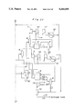
- FIG. 1 is a diagram showing one half of a plant which is suitable for applying a first embodiment of the method for liquefying natural gas according to the present invention.
- FIG. 2 is a diagram showing the other half of the plant which is suitable for applying the first embodiment of the method for liquefying natural gas according to the present invention
- FIG. 3 is a diagram showing one half of a plant which is suitable for applying a second embodiment of the present invention.
- FIG. 4 is a diagram showing the other half of the plant which is suitable for applying the second embodiment of the present invention.
- FIG. 5 is a diagram showing one half of a plant which is suitable for applying a third embodiment of the present invention.
- FIG. 6 is a diagram showing the other half of the plant which is suitable for applying the third embodiment of the present invention.
- FIG. 7 is a diagram showing an essential part of a plant which is suitable for applying a fourth embodiment of the present invention.
- FIG. 8 is a diagram showing an essential part of a plant which is suitable for applying a fifth embodiment of the present invention.
- FIG. 9 is a diagram showing an essential part of a plant which is suitable for applying a sixth embodiment of the present invention.
- FIG. 10 is a diagram showing one half of a plant which is suitable for applying a seventh embodiment of the present invention.
- FIG. 11 is a diagram showing the other half of the plant which is suitable for applying the seventh embodiment of the present invention.
- FIG. 12 is a diagram showing an essential part of a plant which is suitable for applying a eighth embodiment of the present invention.
- FIG. 1 shows a first embodiment of the method for liquefying natural gas according to the present invention.
- High pressure natural gas from which acid gases such as CO 2 and H 2 S are removed is introduced into a plate-fin heat exchanger 1 as feed gas *1 at 44 bar and 35° C.
- the composition of the feed gas is as given in the following:
- the feed gas is cooled to approximately 20° C. by a mixed refrigerant, and most of its water content is condensed and separated in a separation drum 2.
- the water content is further reduced in a dryer 3 below 1 wt ppm, and the natural gas is returned to the plate-fin heat exchanger 1 to be cooled to -24 ° C. by the mixed refrigerant.
- the output from the plate-fin heat exchanger 1 is then fed to a heavy fraction separation tower 4 where a heavy fraction is separated from the natural gas for the purpose of removing a C 5+ fraction which freezes at the temperature of LNG or -160° C.
- the overhead of the reflux from the separation tower 4 is cooled in the plate-fin heat exchanger 1, and the liquid content thereof is separated in a reflux drum 5 and recycled while the vapor from the reflux drum 5 is cooled in the plate-fin heat exchanger 1 to approximately -73° C. by the mixed refrigerant so as to be partially liquefied (approximately 30 wt %), and fed to an expander inlet drum 6.
- the heavy fraction separated in the separation tower 4 contains methane, ethane, propane, butane and so forth, and they are recovered in a distillation section. Methane and ethane are separated in an ethane removal tower, and propane and butane are separated in a propane removal tower and a butane removal tower, respectively. So that the latter two compounds may be mixed with LNG, the propane and butane are combined at the ambient temperature, and this mixed gas stream 2 is introduced into the plate-fin heat exchanger 1 where it is cooled to -24° C. in the same way as the feed natural gas, and joined with the methane-ethane stream *4 from the ethane removal tower.
- the mixed stream then leaves the plate-fin heat exchanger 1 after being cooled to -73° C. This stream is called the re-injection stream.
- Stream *3 is introduced into a reflux condenser of the ethane removal tower at 0° C., and is cooled to -23 ° C.
- the non-liquefied part of the natural gas separated in the expander inlet drum 6 is expanded to 3 bar and cooled to -143° C. as an isentropic expansion process in a turbo expander 7, and is fed to an expander outlet drum 8 in a partially liquefied condition (approximately 21 wt %).
- the separated non-liquefied natural gas then exchanges heat, in a plate-fin heat exchanger 9, with the liquid part separated in the expander inlet drum 6 and the re-injection stream from the plate-fin heat exchanger 1, cooling the latter streams to -141° C. while the separated non-liquified natural gas is warmed to -76° C.
- the latter stream is then pressurized to 8 bar by a compressor 10 directly connected to the expander 7.
- the latter flow is further pressurized by a recycle compressor 11 to 42 bar, and after being cooled to 32° C. by an after-cooler 12, it is introduced again into the plate-fin heat exchanger 1 to be cooled to approximately -86° C. by the mixed refrigerant.
- the stream is partly liquefied (approximately 23 wt %) in a similar manner as the feed natural gas, and is introduced into an expander inlet drum 6'.
- the non-liquefied natural gas separated in this drum is expanded to 3 bar and cooled to -147° C. in a turbo expander 7' as a substantially isentropic expansion process, and the stream expelled from the expander, which is partly (approximately 26 wt %) liquefied, is introduced into an expander outlet drum 8'.
- the non-liquefied natural gas separated in this drum exchanges heat with the liquid part separated in the expander inlet drum 6' in a plate-fin heat exchanger 9' where the separated liquid is cooled to -144° C.
- the liquid cooled in the plate-fin heat exchanger 9 is depressurized by a valve, and is then introduced into the expander outlet drum 8.
- the liquid cooled in the plate-fin heat exchanger 9' is also depressurized by a valve, and is introduced into the expander outlet drum 8'.
- the stream out of the expander outlet drums 8 and 8' is depressurized to 1.3 bar and cooled to -157° C., and is separated into LNG and lean gas in a flash drum 13.
- the lean gas is pressurized by a compressor 14 at the rate of 5,600 Nm 3 , and is used as fuel gas.
- the liquid separated in the flash drum 13 is pumped into a storage tank by a pump 15 at the rate of 305 tons per hour.
- the low pressure mixed refrigerant which has been warmed and evaporated in the plate-fin heat exchanger 1 has the composition given in Table 2, and leaves the heat exchanger at 30° C. and 3.4 bar. This stream is compressed to 26 bar and heated to 130° C. in the turbo compressor 16.
- the compressed mixed refrigerant is cooled in an after-cooler 17 by sea water or the like to 32° C., and 66 wt % thereof is liquefied.
- the liquefied mixed refrigerant is separated into vapor and liquid in a gas/liquid separation drum 18.
- the preferred range of the composition (mol %) of the mixed refrigerant is as given in the following.
- the separated vapor of the high temperature mixed refrigerant is cooled and liquefied in the plate-fin heat exchanger 1 by the low pressure mixed refrigerant as it flows through the heat exchanger.
- the temperature at the outlet end of the heat exchanger is -86° C.
- this high pressure mixed refrigerant liquid is depressurized to 3.8 bar with a J-T valve, a part thereof evaporates, and the stream is turned into a stream of gas/liquid mixed phases at the temperature of -100° C. It is then separated into gas and liquid in a gas/liquid separation drum 19, and is distributed into different paths in the plate-fin heat exchanger 1 so as not to reduce the performance of the plate-fin heat exchanger 1.
- the distributed mixed refrigerant cools other streams in the heat exchanger 1, and is evaporated and warmed to the temperature of -49° C. before it is introduced into a gas/liquid separation drum 20 after leaving the plate-fin heat exchanger 1.
- the high pressure mixed refrigerant expelled from the gas/liquid separation drum 18 is introduced into the plate-fin heat exchanger 1 where the stream is sub-cooled to -47° C., and after flowing out of the heat exchanger 1, is depressurized to 3.6 bar with a J-T valve, and turned into gas and liquid mixed phases with a part thereof being evaporated.
- This stream is then introduced into the gas and liquid separation drum 20 along with the aforementioned low pressure mixed refrigerant, and is separated into gas and liquid.
- the mixed phase stream is then distributed evenly to different paths of the plate-fin heat exchanger 1 so as not to lower the performance of the plate-fin heat exchanger 1.
- the distributed mixed refrigerant is warmed and evaporated as it cools other streams, and after being expelled from the plate-fin heat exchanger 1, is returned to the turbo compressor 16. This concludes the recycling process.
- the power required for the expanders and the compressors used in the present embodiment are listed in Table 4.
- the low power consumption levels of compressors 11 and 11' were achieved as a result of providing an inter-cooler.
- FIGS. 3 and 4 show a second embodiment of the present invention, and in this and the following embodiments, the parts corresponding to those of the first embodiment are denoted with like numerals without repeating the description.
- the output pressures of the expanders 7 and 7' are appropriately selected so as to equalize the output pressures of the expander/compressors 10 and 10', respectively, with the result that the recycle compressors 11 and 11' of the first embodiment may be integrated into one and the same compressor.
- the compressor 11' may be constructed as one having a single casing.
- FIGS. 5 and 6 show a third embodiment of the present invention.
- the pressure of the recycle gas system is raised to the level of the pressure of the feed gas system so that the expanders 7 and 7' for the feed gas system and the recycle gas system may be integrated into one and the same expander, and the recycle compressors 11 and 11' may be likewise integrated into a common compressor.
- the plate-fin heat exchangers 9 and 9' may also be combined into a single plate-fin heat exchanger 9.
- FIG. 7 shows a fourth embodiment of the present invention.
- a separate heat exchanger 21 may be provided so that the vapor pressure of the high pressure mixed refrigerant may be controlled by using a part of the liquid content thereof.
- a reflux condenser 22 can be provided separately from the heat exchanger. This reflux condenser 22 uses a part of the liquid component of the high pressure mixed refrigerant sub-cooled in the plate-fin heat exchanger 1.
- FIG. 8 shows a fifth embodiment of the present invention.
- an inter-cooler 17' is used for the purpose of reducing the power requirement by the refrigerant compressor 16.
- a part of the mixed refrigerant liquefies in the inter-cooler 17', and this liquid part is separated by a separation drum 18' and pressurized by a pump 24 to be eventually introduced into an after-cooler 17.
- This embodiment allows reduction in the power consumption.
- FIG. 9 shows a sixth embodiment of the present invention.
- This embodiment is substantially similar to the first embodiment, but, since the recycle gas is at a super-critical pressure, partial liquefaction would not take place in the plate-fin heat exchanger, and the natural gas is simply cooled. Therefore, the non-liquefied gas component at the outlet end of the turbo expander 7' for the recycle gas is not warmed by the heat exchanger but is compressed forthwith.
- FIGS. 10 and 11 show a seventh embodiment of the present invention.
- This embodiment is substantially similar to the first embodiment, but the propane and butane re-injections are admitted into the outlet of the reflux drum 5, and freezing of normal butane in the plate-fin heat exchanger 9 is avoided. Meanwhile, the methane and ethane from the ethane removal tower is cooled by the plate-fin heat exchanger 9 in the same way as in the first embodiment. This is because of the difficulty in raising the pressure of this stream to the level of the feed natural gas.
- FIG. 12 shows an eighth embodiment of the present invention.
- the output pressure of the expander 7 is set substantially equal to the atmospheric pressure, and the fuel gas for the plant is obtained from the feed natural gas or the recycle natural gas. Therefore, the need for the flash drum 13 and the fuel gas compressor 14 is eliminated.
- the present invention provides a method for liquefying natural gas which can be readily adapted to LNG plants of all sizes without requiring expensive and special heat exchangers.
Abstract
Description
______________________________________
         N.sub.2
             0-10
         C.sub.1
             7-60
         C.sub.2
             25-80
         C.sub.3
             3-20
         C.sub.4
             7-30
         C.sub.5
              7-30,
______________________________________
              TABLE 1
______________________________________
Composition of the Feed Gas (mol %)
______________________________________
        N.sub.2
             0.05
        C.sub.1
             98.52
        C.sub.2
             4.93
        C.sub.3
             2.81
        C.sub.4
             1.22
        C.sub.5+
             0.47
        total
             100.00
flow rate 18,270 kg-mol/h
______________________________________
              TABLE 2
______________________________________
Composition of the Mixed Refrigerant (mol %)
______________________________________
        C.sub.1
             13.96
        C.sub.2
             48.85
        C.sub.3
             7.18
        iC.sub.4
             6.16
        nC.sub.4
             9.95
        iC.sub.5
             13.91
        total
             100.00
flow rate 32,500 kg-mol/h
______________________________________
              TABLE 3
______________________________________
Composition of the Mixed Refrigerant (mol %)
______________________________________
         N.sub.2
             0-10
         C.sub.1
             7-60
         C.sub.2
             25-80
         C.sub.3
             3-20
         C.sub.4
             7-30
         C.sub.5
             7-30
______________________________________
              TABLE 4
______________________________________
Power consumption (kW)
______________________________________
       expander 7
                  7,200
       expander 7'
                  8,600
       compressor 11
                 16,000
       compressor 11'
                 21,200
       compressor 16
                 58,100
______________________________________
Claims (12)
______________________________________
         N.sub.2
             0-10
         C.sub.1
             7-60
         C.sub.2
             25-80
         C.sub.3
             3-20
         C.sub.4
             7-30
         C.sub.5
             7-30
______________________________________
Applications Claiming Priority (2)
| Application Number | Priority Date | Filing Date | Title |
|---|---|---|---|
| JP4-335540 | 1992-11-20 | ||
| JP4335540A JPH06159928A (en) | 1992-11-20 | 1992-11-20 | Liquefying method for natural gas |
Publications (1)
| Publication Number | Publication Date |
|---|---|
| US5363655A true US5363655A (en) | 1994-11-15 |
Family
ID=18289721
Family Applications (1)
| Application Number | Title | Priority Date | Filing Date |
|---|---|---|---|
| US08/028,025 Expired - Fee Related US5363655A (en) | 1992-11-20 | 1993-03-08 | Method for liquefying natural gas |
Country Status (6)
| Country | Link |
|---|---|
| US (1) | US5363655A (en) |
| EP (1) | EP0599443B1 (en) |
| JP (1) | JPH06159928A (en) |
| KR (1) | KR0145174B1 (en) |
| CA (1) | CA2090809C (en) |
| DE (1) | DE69313977D1 (en) |
Cited By (58)
| Publication number | Priority date | Publication date | Assignee | Title |
|---|---|---|---|---|
| WO1996014547A1 (en) * | 1994-11-08 | 1996-05-17 | Williams Field Services - Rocky Mountain Company | Lng production in cryogenic natural gas processing plants |
| US5537827A (en) * | 1995-06-07 | 1996-07-23 | Low; William R. | Method for liquefaction of natural gas |
| US5657643A (en) * | 1996-02-28 | 1997-08-19 | The Pritchard Corporation | Closed loop single mixed refrigerant process |
| US5718126A (en) * | 1995-10-11 | 1998-02-17 | Institut Francais Du Petrole | Process and device for liquefying and for processing a natural gas |
| WO1998059205A2 (en) * | 1997-06-20 | 1998-12-30 | Exxon Production Research Company | Improved process for liquefaction of natural gas |
| US5950453A (en) * | 1997-06-20 | 1999-09-14 | Exxon Production Research Company | Multi-component refrigeration process for liquefaction of natural gas |
| US6062041A (en) * | 1997-01-27 | 2000-05-16 | Chiyoda Corporation | Method for liquefying natural gas |
| US6192705B1 (en) | 1998-10-23 | 2001-02-27 | Exxonmobil Upstream Research Company | Reliquefaction of pressurized boil-off from pressurized liquid natural gas |
| US6209350B1 (en) | 1998-10-23 | 2001-04-03 | Exxonmobil Upstream Research Company | Refrigeration process for liquefaction of natural gas |
| US6250105B1 (en) | 1998-12-18 | 2001-06-26 | Exxonmobil Upstream Research Company | Dual multi-component refrigeration cycles for liquefaction of natural gas |
| WO2001046634A1 (en) * | 1999-12-22 | 2001-06-28 | Phillips Petroleum Company | Efficiency improvement of open-cycle cascaded refrigeration process for lng production |
| US6378330B1 (en) | 1999-12-17 | 2002-04-30 | Exxonmobil Upstream Research Company | Process for making pressurized liquefied natural gas from pressured natural gas using expansion cooling |
| US6526777B1 (en) | 2001-04-20 | 2003-03-04 | Elcor Corporation | LNG production in cryogenic natural gas processing plants |
| US6564578B1 (en) | 2002-01-18 | 2003-05-20 | Bp Corporation North America Inc. | Self-refrigerated LNG process |
| US20030158458A1 (en) * | 2002-02-20 | 2003-08-21 | Eric Prim | System and method for recovery of C2+ hydrocarbons contained in liquefied natural gas |
| US20040079107A1 (en) * | 2002-10-23 | 2004-04-29 | Wilkinson John D. | Natural gas liquefaction |
| US6742358B2 (en) | 2001-06-08 | 2004-06-01 | Elkcorp | Natural gas liquefaction |
| US20050066686A1 (en) * | 2003-09-30 | 2005-03-31 | Elkcorp | Liquefied natural gas processing |
| US6889523B2 (en) | 2003-03-07 | 2005-05-10 | Elkcorp | LNG production in cryogenic natural gas processing plants |
| US20050144979A1 (en) * | 2004-01-06 | 2005-07-07 | Zollinger William T. | Method of liquifying a gas |
| US20050180915A1 (en) * | 2004-02-13 | 2005-08-18 | Bingham Dennis N. | Method of producing hydrogen |
| US20050247078A1 (en) * | 2004-05-04 | 2005-11-10 | Elkcorp | Natural gas liquefaction |
| US20050279133A1 (en) * | 2004-06-16 | 2005-12-22 | Eaton Anthony P | Semi-closed loop LNG process |
| US20060000234A1 (en) * | 2004-07-01 | 2006-01-05 | Ortloff Engineers, Ltd. | Liquefied natural gas processing |
| US20060032269A1 (en) * | 2003-02-25 | 2006-02-16 | Ortloff Engineers, Ltd. | Hydrocarbon gas processing |
| US20060228295A1 (en) * | 2004-02-13 | 2006-10-12 | Battelle Energy Alliance, Llc | Method of producing hydrogen, and rendering a contaminated biomass inert |
| US20070283718A1 (en) * | 2006-06-08 | 2007-12-13 | Hulsey Kevin H | Lng system with optimized heat exchanger configuration |
| US20080000265A1 (en) * | 2006-06-02 | 2008-01-03 | Ortloff Engineers, Ltd. | Liquefied Natural Gas Processing |
| US20080190136A1 (en) * | 2007-02-09 | 2008-08-14 | Ortloff Engineers, Ltd. | Hydrocarbon Gas Processing |
| US20080196384A1 (en) * | 2007-02-16 | 2008-08-21 | Denis Ding | Recipicating compressor with inlet booster for cng station and refueling motor vehicles |
| US20080282731A1 (en) * | 2007-05-17 | 2008-11-20 | Ortloff Engineers, Ltd. | Liquefied Natural Gas Processing |
| US20090071190A1 (en) * | 2007-03-26 | 2009-03-19 | Richard Potthoff | Closed cycle mixed refrigerant systems |
| US20090100862A1 (en) * | 2007-10-18 | 2009-04-23 | Ortloff Engineers, Ltd. | Hydrocarbon Gas Processing |
| US20090113928A1 (en) * | 2007-11-05 | 2009-05-07 | David Vandor | Method and System for the Small-scale Production of Liquified Natural Gas (LNG) from Low-pressure Gas |
| US20090301132A1 (en) * | 2007-12-10 | 2009-12-10 | Conocophillips Company | Optimized heavies removal system in an lng facility |
| US7642292B2 (en) | 2005-03-16 | 2010-01-05 | Fuelcor Llc | Systems, methods, and compositions for production of synthetic hydrocarbon compounds |
| US20100031700A1 (en) * | 2008-08-06 | 2010-02-11 | Ortloff Engineers, Ltd. | Liquefied natural gas and hydrocarbon gas processing |
| US20110167868A1 (en) * | 2010-01-14 | 2011-07-14 | Ortloff Engineers, Ltd. | Hydrocarbon gas processing |
| US20110240139A1 (en) * | 2007-02-16 | 2011-10-06 | Denis Ding | Reciprocating compressor with inlet booster for cng station and refueling motor vehicles |
| US20120090350A1 (en) * | 2010-10-15 | 2012-04-19 | Fluor Technologies Corporation | Configurations and Methods of Heating Value Control in LNG Liquefaction Plant |
| US8434325B2 (en) | 2009-05-15 | 2013-05-07 | Ortloff Engineers, Ltd. | Liquefied natural gas and hydrocarbon gas processing |
| WO2013096464A1 (en) * | 2011-12-20 | 2013-06-27 | Conocophillips Company | Liquefying natural gas in a motion environment |
| US8667812B2 (en) | 2010-06-03 | 2014-03-11 | Ordoff Engineers, Ltd. | Hydrocabon gas processing |
| US8794030B2 (en) | 2009-05-15 | 2014-08-05 | Ortloff Engineers, Ltd. | Liquefied natural gas and hydrocarbon gas processing |
| US8850849B2 (en) | 2008-05-16 | 2014-10-07 | Ortloff Engineers, Ltd. | Liquefied natural gas and hydrocarbon gas processing |
| WO2015153097A1 (en) * | 2014-04-02 | 2015-10-08 | Dresser-Rand Company | System and method for the production of liquefied natural gas |
| WO2016032701A1 (en) * | 2014-08-29 | 2016-03-03 | Black & Veatch Holding Company | Dual mixed refrigerant system |
| WO2016032697A1 (en) * | 2014-08-29 | 2016-03-03 | Black & Veatch Holding Company | Dual mixed refrigerant system |
| WO2016032700A1 (en) * | 2014-08-29 | 2016-03-03 | Black & Veatch Holding Company | Dual mixed refrigerant system |
| US9829244B2 (en) | 2010-07-29 | 2017-11-28 | Fluor Technologies Corporation | Configurations and methods for small scale LNG production |
| US10533794B2 (en) | 2016-08-26 | 2020-01-14 | Ortloff Engineers, Ltd. | Hydrocarbon gas processing |
| US10551118B2 (en) | 2016-08-26 | 2020-02-04 | Ortloff Engineers, Ltd. | Hydrocarbon gas processing |
| US10551119B2 (en) | 2016-08-26 | 2020-02-04 | Ortloff Engineers, Ltd. | Hydrocarbon gas processing |
| US11112173B2 (en) | 2016-07-01 | 2021-09-07 | Fluor Technologies Corporation | Configurations and methods for small scale LNG production |
| US20210364231A1 (en) * | 2020-05-21 | 2021-11-25 | EnFlex, Inc. | Advanced Method of Heavy Hydrocarbon Removal and Natural Gas Liquefaction Using Closed-Loop Refrigeration System |
| FR3116326A1 (en) * | 2020-11-17 | 2022-05-20 | Technip France | Process for producing liquefied natural gas from natural gas, and corresponding installation |
| US11428465B2 (en) | 2017-06-01 | 2022-08-30 | Uop Llc | Hydrocarbon gas processing |
| US11543180B2 (en) | 2017-06-01 | 2023-01-03 | Uop Llc | Hydrocarbon gas processing |
Families Citing this family (14)
| Publication number | Priority date | Publication date | Assignee | Title |
|---|---|---|---|---|
| NO305853B1 (en) * | 1997-01-29 | 1999-08-09 | Norske Stats Oljeselskap | Procedure for reducing emissions of volatile organic compounds |
| FR2772896B1 (en) * | 1997-12-22 | 2000-01-28 | Inst Francais Du Petrole | METHOD FOR THE LIQUEFACTION OF A GAS, PARTICULARLY A NATURAL GAS OR AIR COMPRISING A MEDIUM PRESSURE PURGE AND ITS APPLICATION |
| TW477890B (en) * | 1998-05-21 | 2002-03-01 | Shell Int Research | Method of liquefying a stream enriched in methane |
| US6041620A (en) * | 1998-12-30 | 2000-03-28 | Praxair Technology, Inc. | Cryogenic industrial gas liquefaction with hybrid refrigeration generation |
| FR2803851B1 (en) | 2000-01-19 | 2006-09-29 | Inst Francais Du Petrole | PROCESS FOR PARTIALLY LIQUEFACTING A FLUID CONTAINING HYDROCARBONS SUCH AS NATURAL GAS |
| NO312736B1 (en) * | 2000-02-10 | 2002-06-24 | Sinvent As | Method and plant for cooling and possibly liquefying a product gas |
| GB0120272D0 (en) * | 2001-08-21 | 2001-10-10 | Gasconsult Ltd | Improved process for liquefaction of natural gases |
| DE10337517A1 (en) * | 2003-08-14 | 2005-03-10 | Linde Ag | A process for liquefying a hydrocarbon-rich stream while recovering a C¶¶¶¶ + ¶ -rich fraction in high yield |
| JP4551446B2 (en) * | 2004-04-26 | 2010-09-29 | オートロフ・エンジニアーズ・リミテッド | Natural gas liquefaction |
| US20090217701A1 (en) * | 2005-08-09 | 2009-09-03 | Moses Minta | Natural Gas Liquefaction Process for Ling |
| US9377239B2 (en) | 2007-11-15 | 2016-06-28 | Conocophillips Company | Dual-refluxed heavies removal column in an LNG facility |
| DE102010062044A1 (en) * | 2010-11-26 | 2012-05-31 | Siemens Aktiengesellschaft | Liquefied natural gas (LNG) plant has relaxation gas line that is extended from relaxation drum to relaxation gas unit and is isolated from gas liquefaction plant to conduct relaxation gas to relaxation gas unit |
| KR101106088B1 (en) * | 2011-03-22 | 2012-01-18 | 대우조선해양 주식회사 | Non-flammable mixed refrigerant using for reliquifaction apparatus in system for supplying fuel for high pressure natural gas injection engine |
| KR101444121B1 (en) * | 2012-11-14 | 2014-09-26 | 삼성중공업 주식회사 | BOG Treating System Using Expending Energy of Gas Fuel |
Citations (4)
| Publication number | Priority date | Publication date | Assignee | Title |
|---|---|---|---|---|
| US4229195A (en) * | 1978-05-09 | 1980-10-21 | Linde Aktiengesellschaft | Method for liquifying natural gas |
| US4256476A (en) * | 1979-05-04 | 1981-03-17 | Hydrocarbon Research, Inc. | Low temperature process for the recovery of ethane from thermal hydrocracking vent gases |
| US4303427A (en) * | 1976-06-23 | 1981-12-01 | Heinrich Krieger | Cascade multicomponent cooling method for liquefying natural gas |
| US4619679A (en) * | 1984-10-29 | 1986-10-28 | Phillips Petroleum Company | Gas processing |
Family Cites Families (3)
| Publication number | Priority date | Publication date | Assignee | Title |
|---|---|---|---|---|
| JPS4921699B1 (en) * | 1970-11-28 | 1974-06-03 | ||
| US4504296A (en) * | 1983-07-18 | 1985-03-12 | Air Products And Chemicals, Inc. | Double mixed refrigerant liquefaction process for natural gas |
| US4970867A (en) * | 1989-08-21 | 1990-11-20 | Air Products And Chemicals, Inc. | Liquefaction of natural gas using process-loaded expanders |
-
1992
- 1992-11-20 JP JP4335540A patent/JPH06159928A/en active Pending
-
1993
- 1993-03-02 CA CA002090809A patent/CA2090809C/en not_active Expired - Fee Related
- 1993-03-08 US US08/028,025 patent/US5363655A/en not_active Expired - Fee Related
- 1993-03-08 DE DE69313977T patent/DE69313977D1/en not_active Expired - Lifetime
- 1993-03-08 EP EP93301750A patent/EP0599443B1/en not_active Expired - Lifetime
- 1993-03-23 KR KR1019930004477A patent/KR0145174B1/en not_active IP Right Cessation
Patent Citations (4)
| Publication number | Priority date | Publication date | Assignee | Title |
|---|---|---|---|---|
| US4303427A (en) * | 1976-06-23 | 1981-12-01 | Heinrich Krieger | Cascade multicomponent cooling method for liquefying natural gas |
| US4229195A (en) * | 1978-05-09 | 1980-10-21 | Linde Aktiengesellschaft | Method for liquifying natural gas |
| US4256476A (en) * | 1979-05-04 | 1981-03-17 | Hydrocarbon Research, Inc. | Low temperature process for the recovery of ethane from thermal hydrocracking vent gases |
| US4619679A (en) * | 1984-10-29 | 1986-10-28 | Phillips Petroleum Company | Gas processing |
Cited By (104)
| Publication number | Priority date | Publication date | Assignee | Title |
|---|---|---|---|---|
| US5615561A (en) * | 1994-11-08 | 1997-04-01 | Williams Field Services Company | LNG production in cryogenic natural gas processing plants |
| WO1996014547A1 (en) * | 1994-11-08 | 1996-05-17 | Williams Field Services - Rocky Mountain Company | Lng production in cryogenic natural gas processing plants |
| US5537827A (en) * | 1995-06-07 | 1996-07-23 | Low; William R. | Method for liquefaction of natural gas |
| US5718126A (en) * | 1995-10-11 | 1998-02-17 | Institut Francais Du Petrole | Process and device for liquefying and for processing a natural gas |
| US5657643A (en) * | 1996-02-28 | 1997-08-19 | The Pritchard Corporation | Closed loop single mixed refrigerant process |
| US6062041A (en) * | 1997-01-27 | 2000-05-16 | Chiyoda Corporation | Method for liquefying natural gas |
| GB2344640A (en) * | 1997-06-20 | 2000-06-14 | Exxon Production Research Co | Improved process for liquefaction of natural gas |
| GB2344640B (en) * | 1997-06-20 | 2001-06-27 | Exxon Production Research Co | Improved process for liquefaction of natural gas |
| US6023942A (en) * | 1997-06-20 | 2000-02-15 | Exxon Production Research Company | Process for liquefaction of natural gas |
| WO1998059205A3 (en) * | 1997-06-20 | 1999-03-18 | Exxon Production Research Co | Improved process for liquefaction of natural gas |
| ES2197720A1 (en) * | 1997-06-20 | 2004-01-01 | Exxonmobil Upstream Res Co | Improved process for liquefaction of natural gas |
| EP1021689A2 (en) * | 1997-06-20 | 2000-07-26 | Exxon Mobil Upstream Research Company | Improved process for liquefaction of natural gas |
| WO1998059205A2 (en) * | 1997-06-20 | 1998-12-30 | Exxon Production Research Company | Improved process for liquefaction of natural gas |
| CZ299027B6 (en) * | 1997-06-20 | 2008-04-09 | Exxonmobil Upstream Research Company | Enhanced process for liquefying natural gas |
| AT413598B (en) * | 1997-06-20 | 2006-04-15 | Exxonmobil Upstream Res Co | IMPROVED PROCESS FOR LIQUEFYING NATURAL GAS |
| US5950453A (en) * | 1997-06-20 | 1999-09-14 | Exxon Production Research Company | Multi-component refrigeration process for liquefaction of natural gas |
| EP1021689A4 (en) * | 1997-06-20 | 2002-11-20 | Exxonmobil Upstream Res Co | Improved process for liquefaction of natural gas |
| US6209350B1 (en) | 1998-10-23 | 2001-04-03 | Exxonmobil Upstream Research Company | Refrigeration process for liquefaction of natural gas |
| US6192705B1 (en) | 1998-10-23 | 2001-02-27 | Exxonmobil Upstream Research Company | Reliquefaction of pressurized boil-off from pressurized liquid natural gas |
| US6250105B1 (en) | 1998-12-18 | 2001-06-26 | Exxonmobil Upstream Research Company | Dual multi-component refrigeration cycles for liquefaction of natural gas |
| US6378330B1 (en) | 1999-12-17 | 2002-04-30 | Exxonmobil Upstream Research Company | Process for making pressurized liquefied natural gas from pressured natural gas using expansion cooling |
| US6289692B1 (en) * | 1999-12-22 | 2001-09-18 | Phillips Petroleum Company | Efficiency improvement of open-cycle cascaded refrigeration process for LNG production |
| WO2001046634A1 (en) * | 1999-12-22 | 2001-06-28 | Phillips Petroleum Company | Efficiency improvement of open-cycle cascaded refrigeration process for lng production |
| US6526777B1 (en) | 2001-04-20 | 2003-03-04 | Elcor Corporation | LNG production in cryogenic natural gas processing plants |
| US7210311B2 (en) | 2001-06-08 | 2007-05-01 | Ortloff Engineers, Ltd. | Natural gas liquefaction |
| US6742358B2 (en) | 2001-06-08 | 2004-06-01 | Elkcorp | Natural gas liquefaction |
| US7010937B2 (en) | 2001-06-08 | 2006-03-14 | Elkcorp | Natural gas liquefaction |
| US20090293538A1 (en) * | 2001-06-08 | 2009-12-03 | Ortloff Engineers, Ltd. | Natural gas liquefaction |
| US20050268649A1 (en) * | 2001-06-08 | 2005-12-08 | Ortloff Engineers, Ltd. | Natural gas liquefaction |
| US6564578B1 (en) | 2002-01-18 | 2003-05-20 | Bp Corporation North America Inc. | Self-refrigerated LNG process |
| US7069743B2 (en) | 2002-02-20 | 2006-07-04 | Eric Prim | System and method for recovery of C2+ hydrocarbons contained in liquefied natural gas |
| US20030158458A1 (en) * | 2002-02-20 | 2003-08-21 | Eric Prim | System and method for recovery of C2+ hydrocarbons contained in liquefied natural gas |
| US20040079107A1 (en) * | 2002-10-23 | 2004-04-29 | Wilkinson John D. | Natural gas liquefaction |
| US6945075B2 (en) | 2002-10-23 | 2005-09-20 | Elkcorp | Natural gas liquefaction |
| US20060032269A1 (en) * | 2003-02-25 | 2006-02-16 | Ortloff Engineers, Ltd. | Hydrocarbon gas processing |
| US7191617B2 (en) | 2003-02-25 | 2007-03-20 | Ortloff Engineers, Ltd. | Hydrocarbon gas processing |
| US6889523B2 (en) | 2003-03-07 | 2005-05-10 | Elkcorp | LNG production in cryogenic natural gas processing plants |
| US7155931B2 (en) | 2003-09-30 | 2007-01-02 | Ortloff Engineers, Ltd. | Liquefied natural gas processing |
| US20050066686A1 (en) * | 2003-09-30 | 2005-03-31 | Elkcorp | Liquefied natural gas processing |
| US6997012B2 (en) | 2004-01-06 | 2006-02-14 | Battelle Energy Alliance, Llc | Method of Liquifying a gas |
| US20050144979A1 (en) * | 2004-01-06 | 2005-07-07 | Zollinger William T. | Method of liquifying a gas |
| US20050180915A1 (en) * | 2004-02-13 | 2005-08-18 | Bingham Dennis N. | Method of producing hydrogen |
| US7153489B2 (en) | 2004-02-13 | 2006-12-26 | Battelle Energy Alliance, Llc | Method of producing hydrogen |
| US20060228295A1 (en) * | 2004-02-13 | 2006-10-12 | Battelle Energy Alliance, Llc | Method of producing hydrogen, and rendering a contaminated biomass inert |
| US7665328B2 (en) | 2004-02-13 | 2010-02-23 | Battelle Energy Alliance, Llc | Method of producing hydrogen, and rendering a contaminated biomass inert |
| US20050247078A1 (en) * | 2004-05-04 | 2005-11-10 | Elkcorp | Natural gas liquefaction |
| US7204100B2 (en) | 2004-05-04 | 2007-04-17 | Ortloff Engineers, Ltd. | Natural gas liquefaction |
| US7866184B2 (en) * | 2004-06-16 | 2011-01-11 | Conocophillips Company | Semi-closed loop LNG process |
| US20050279133A1 (en) * | 2004-06-16 | 2005-12-22 | Eaton Anthony P | Semi-closed loop LNG process |
| US7216507B2 (en) | 2004-07-01 | 2007-05-15 | Ortloff Engineers, Ltd. | Liquefied natural gas processing |
| US20060000234A1 (en) * | 2004-07-01 | 2006-01-05 | Ortloff Engineers, Ltd. | Liquefied natural gas processing |
| US7863340B2 (en) | 2005-03-16 | 2011-01-04 | Fuelcor Llc | Systems, methods, and compositions for production of synthetic hydrocarbon compounds |
| US7642292B2 (en) | 2005-03-16 | 2010-01-05 | Fuelcor Llc | Systems, methods, and compositions for production of synthetic hydrocarbon compounds |
| US8114916B2 (en) | 2005-03-16 | 2012-02-14 | Fuelcor, Llc | Systems, methods, and compositions for production of synthetic hydrocarbon compounds |
| US8093305B2 (en) | 2005-03-16 | 2012-01-10 | Fuelcor, Llc | Systems, methods, and compositions for production of synthetic hydrocarbon compounds |
| US8168143B2 (en) | 2005-03-16 | 2012-05-01 | Fuelcor, Llc | Systems, methods, and compositions for production of synthetic hydrocarbon compounds |
| US20080000265A1 (en) * | 2006-06-02 | 2008-01-03 | Ortloff Engineers, Ltd. | Liquefied Natural Gas Processing |
| US7631516B2 (en) | 2006-06-02 | 2009-12-15 | Ortloff Engineers, Ltd. | Liquefied natural gas processing |
| US20070283718A1 (en) * | 2006-06-08 | 2007-12-13 | Hulsey Kevin H | Lng system with optimized heat exchanger configuration |
| WO2007142668A1 (en) * | 2006-06-08 | 2007-12-13 | Conocophillips Company | Lng system with optimized heat exchanger configuration |
| US8590340B2 (en) | 2007-02-09 | 2013-11-26 | Ortoff Engineers, Ltd. | Hydrocarbon gas processing |
| US20080190136A1 (en) * | 2007-02-09 | 2008-08-14 | Ortloff Engineers, Ltd. | Hydrocarbon Gas Processing |
| US20080196384A1 (en) * | 2007-02-16 | 2008-08-21 | Denis Ding | Recipicating compressor with inlet booster for cng station and refueling motor vehicles |
| US7967036B2 (en) * | 2007-02-16 | 2011-06-28 | Clean Energy Fuels Corp. | Recipicating compressor with inlet booster for CNG station and refueling motor vehicles |
| US8839829B2 (en) * | 2007-02-16 | 2014-09-23 | Clean Energy Fuels Corp. | Reciprocating compressor with inlet booster for CNG station and refueling motor vehicles |
| US20110240139A1 (en) * | 2007-02-16 | 2011-10-06 | Denis Ding | Reciprocating compressor with inlet booster for cng station and refueling motor vehicles |
| US20090071190A1 (en) * | 2007-03-26 | 2009-03-19 | Richard Potthoff | Closed cycle mixed refrigerant systems |
| US9869510B2 (en) | 2007-05-17 | 2018-01-16 | Ortloff Engineers, Ltd. | Liquefied natural gas processing |
| US20080282731A1 (en) * | 2007-05-17 | 2008-11-20 | Ortloff Engineers, Ltd. | Liquefied Natural Gas Processing |
| US20090100862A1 (en) * | 2007-10-18 | 2009-04-23 | Ortloff Engineers, Ltd. | Hydrocarbon Gas Processing |
| US8919148B2 (en) | 2007-10-18 | 2014-12-30 | Ortloff Engineers, Ltd. | Hydrocarbon gas processing |
| US8020406B2 (en) | 2007-11-05 | 2011-09-20 | David Vandor | Method and system for the small-scale production of liquified natural gas (LNG) from low-pressure gas |
| US20090113928A1 (en) * | 2007-11-05 | 2009-05-07 | David Vandor | Method and System for the Small-scale Production of Liquified Natural Gas (LNG) from Low-pressure Gas |
| US20090301132A1 (en) * | 2007-12-10 | 2009-12-10 | Conocophillips Company | Optimized heavies removal system in an lng facility |
| US8505333B2 (en) | 2007-12-10 | 2013-08-13 | Conocophilips Company | Optimized heavies removal system in an LNG facility |
| US8850849B2 (en) | 2008-05-16 | 2014-10-07 | Ortloff Engineers, Ltd. | Liquefied natural gas and hydrocarbon gas processing |
| US20110120183A9 (en) * | 2008-08-06 | 2011-05-26 | Ortloff Engineers, Ltd. | Liquefied natural gas and hydrocarbon gas processing |
| US20100031700A1 (en) * | 2008-08-06 | 2010-02-11 | Ortloff Engineers, Ltd. | Liquefied natural gas and hydrocarbon gas processing |
| US8584488B2 (en) | 2008-08-06 | 2013-11-19 | Ortloff Engineers, Ltd. | Liquefied natural gas production |
| US8794030B2 (en) | 2009-05-15 | 2014-08-05 | Ortloff Engineers, Ltd. | Liquefied natural gas and hydrocarbon gas processing |
| US8434325B2 (en) | 2009-05-15 | 2013-05-07 | Ortloff Engineers, Ltd. | Liquefied natural gas and hydrocarbon gas processing |
| US9021832B2 (en) | 2010-01-14 | 2015-05-05 | Ortloff Engineers, Ltd. | Hydrocarbon gas processing |
| US20110167868A1 (en) * | 2010-01-14 | 2011-07-14 | Ortloff Engineers, Ltd. | Hydrocarbon gas processing |
| US8667812B2 (en) | 2010-06-03 | 2014-03-11 | Ordoff Engineers, Ltd. | Hydrocabon gas processing |
| US9829244B2 (en) | 2010-07-29 | 2017-11-28 | Fluor Technologies Corporation | Configurations and methods for small scale LNG production |
| US20120090350A1 (en) * | 2010-10-15 | 2012-04-19 | Fluor Technologies Corporation | Configurations and Methods of Heating Value Control in LNG Liquefaction Plant |
| US8635885B2 (en) * | 2010-10-15 | 2014-01-28 | Fluor Technologies Corporation | Configurations and methods of heating value control in LNG liquefaction plant |
| RU2620310C2 (en) * | 2011-12-20 | 2017-05-24 | Конокофиллипс Компани | Liquefying of natural gas in moving environment |
| WO2013096464A1 (en) * | 2011-12-20 | 2013-06-27 | Conocophillips Company | Liquefying natural gas in a motion environment |
| CN104011487A (en) * | 2011-12-20 | 2014-08-27 | 科诺科菲利浦公司 | Liquefying natural gas in a motion environment |
| WO2015153097A1 (en) * | 2014-04-02 | 2015-10-08 | Dresser-Rand Company | System and method for the production of liquefied natural gas |
| WO2016032701A1 (en) * | 2014-08-29 | 2016-03-03 | Black & Veatch Holding Company | Dual mixed refrigerant system |
| WO2016032697A1 (en) * | 2014-08-29 | 2016-03-03 | Black & Veatch Holding Company | Dual mixed refrigerant system |
| WO2016032700A1 (en) * | 2014-08-29 | 2016-03-03 | Black & Veatch Holding Company | Dual mixed refrigerant system |
| US11112173B2 (en) | 2016-07-01 | 2021-09-07 | Fluor Technologies Corporation | Configurations and methods for small scale LNG production |
| US10533794B2 (en) | 2016-08-26 | 2020-01-14 | Ortloff Engineers, Ltd. | Hydrocarbon gas processing |
| US10551119B2 (en) | 2016-08-26 | 2020-02-04 | Ortloff Engineers, Ltd. | Hydrocarbon gas processing |
| US10551118B2 (en) | 2016-08-26 | 2020-02-04 | Ortloff Engineers, Ltd. | Hydrocarbon gas processing |
| US11428465B2 (en) | 2017-06-01 | 2022-08-30 | Uop Llc | Hydrocarbon gas processing |
| US11543180B2 (en) | 2017-06-01 | 2023-01-03 | Uop Llc | Hydrocarbon gas processing |
| US20210364231A1 (en) * | 2020-05-21 | 2021-11-25 | EnFlex, Inc. | Advanced Method of Heavy Hydrocarbon Removal and Natural Gas Liquefaction Using Closed-Loop Refrigeration System |
| US11808518B2 (en) * | 2020-05-21 | 2023-11-07 | EnFlex, Inc. | Advanced method of heavy hydrocarbon removal and natural gas liquefaction using closed-loop refrigeration system |
| FR3116326A1 (en) * | 2020-11-17 | 2022-05-20 | Technip France | Process for producing liquefied natural gas from natural gas, and corresponding installation |
| WO2022106260A1 (en) * | 2020-11-17 | 2022-05-27 | Technip France | Method for producing liquefied natural gas from natural gas, and corresponding plant |
Also Published As
| Publication number | Publication date |
|---|---|
| CA2090809C (en) | 1997-04-08 |
| KR940011616A (en) | 1994-06-21 |
| JPH06159928A (en) | 1994-06-07 |
| DE69313977D1 (en) | 1997-10-23 |
| CA2090809A1 (en) | 1994-05-21 |
| EP0599443B1 (en) | 1997-09-17 |
| KR0145174B1 (en) | 1998-07-15 |
| EP0599443A1 (en) | 1994-06-01 |
Similar Documents
| Publication | Publication Date | Title |
|---|---|---|
| US5363655A (en) | Method for liquefying natural gas | |
| US6253574B1 (en) | Method for liquefying a stream rich in hydrocarbons | |
| US6378330B1 (en) | Process for making pressurized liquefied natural gas from pressured natural gas using expansion cooling | |
| US6119479A (en) | Dual mixed refrigerant cycle for gas liquefaction | |
| US6062041A (en) | Method for liquefying natural gas | |
| CA3053323C (en) | Pre-cooling of natural gas by high pressure compression and expansion | |
| US6347531B1 (en) | Single mixed refrigerant gas liquefaction process | |
| US6751985B2 (en) | Process for producing a pressurized liquefied gas product by cooling and expansion of a gas stream in the supercritical state | |
| RU2270408C2 (en) | Method and device for liquefied gas cooling | |
| CN110418929B (en) | Apparatus and method for liquefaction of natural gas | |
| MX2011005475A (en) | Method for producing a stream of subcooled liquefied natural gas using a natural gas feedstream, and associated facility. | |
| JPH0587558B2 (en) | ||
| RU2568697C2 (en) | Liquefaction of fraction enriched with hydrocarbons | |
| US11815308B2 (en) | Pretreatment and pre-cooling of natural gas by high pressure compression and expansion | |
| EP4031820A1 (en) | Pretreatment, pre-cooling, and condensate recovery of natural gas by high pressure compression and expansion | |
| US11806639B2 (en) | Pretreatment and pre-cooling of natural gas by high pressure compression and expansion | |
| RU2811216C1 (en) | Method for natural gas liquefaction | |
| US20230408187A1 (en) | Method for producing liquefied natural gas from natural gas, and corresponding plant | |
| RU2792387C1 (en) | Method for liquefiting natural gas "modified arctic cascade" and installation for its implementation |
Legal Events
| Date | Code | Title | Description |
|---|---|---|---|
| AS | Assignment |
Owner name: CHIYODA CORPORATION, JAPAN Free format text: ASSIGNMENT OF ASSIGNORS INTEREST.;ASSIGNORS:KIKKAWA, YOSHITSUGI;YAMAMOTO, OSAMU;SAKAGUCHI, JUNICHI;AND OTHERS;REEL/FRAME:006493/0804 Effective date: 19930118 |
|
| FPAY | Fee payment |
Year of fee payment: 4 |
|
| REMI | Maintenance fee reminder mailed | ||
| LAPS | Lapse for failure to pay maintenance fees | ||
| LAPS | Lapse for failure to pay maintenance fees |
Free format text: PATENT EXPIRED FOR FAILURE TO PAY MAINTENANCE FEES (ORIGINAL EVENT CODE: EXP.); ENTITY STATUS OF PATENT OWNER: LARGE ENTITY |
|
| STCH | Information on status: patent discontinuation |
Free format text: PATENT EXPIRED DUE TO NONPAYMENT OF MAINTENANCE FEES UNDER 37 CFR 1.362 |
|
| FP | Lapsed due to failure to pay maintenance fee |
Effective date: 20021115 |